Article

Modeling and Analysis of the Harmonic Interaction between Grid-Connected Inverter Clusters and the Utility Grid

1
School of Mechatronics Engineering and Automation, Shanghai University, Shanghai 200444, China
2
State Grid Shanghai Comprehensive Energy Service Co., Ltd., Shanghai 200023, China
3
Instituto Superior Técnico, University of Lisbon, 999022 Lisbon, Portugal
*
Author to whom correspondence should be addressed.
Energies 2022, 15(10), 3490; https://doi.org/10.3390/en15103490
Submission received: 26 March 2022 / Revised: 24 April 2022 / Accepted: 6 May 2022 / Published: 10 May 2022

Abstract

:
The virtual synchronous generator (VSG) is a promising technology for future utility grids, since it can mimic the output characteristics of a synchronous generator, which provides the necessary inertia to a utility grid. However, the large-scale application of VSGs is limited due to the harmonic interaction between VSGs and the utility grid. Therefore, in order to investigate the stability issue as well as improve the practical application for large-scale power stations, the harmonic interaction mechanism between the VSG cluster and the utility grid is addressed. Firstly, the output impedance model of a single VSG is established, and it is found that the resonance frequency is related to parameters including the output filter, controller, and grid impedance. On this basis, the capacitor current control for a grid-connected inverter based on a VSG is proposed to enhance the resonance suppression. Furthermore, the output impedance of the VSG cluster is established, which reveals the harmonic interaction characteristics between the VSG cluster and the utility grid. In addition, in order to suppress the resonance and improve the stability, an inner-loop control strategy of VSG is introduced. Finally, the simulation and experimental results verified the correctness of the established modeling and analysis of the harmonic interaction between the clustered VSGs and the utility grid. The results show that the proposed impedance model is correct and can predict the resonant point accuracy (which is around 2.3 kHz in the simulation and experimental cases). The total harmonic distortion (THD) can be reduced to 3.2% which meets the requirements of IEEE standard 519.

1. Introduction

With the penetration of renewable energy, which is normally dominated by power electronics converters, the rotating inertia and damping of the utility grid are decreasing, affecting the stability and safety of the grid [1,2,3]. In order to deal with the lack of inertia, VSG technology is proposed, which could be a promising technology for the next generation power grid [4]. The basic idea of a VSG is to simulate the droop characteristics and rotating inertia of traditional synchronous generators [5].
When the distributed energy (for instance, the primary power of PV and wind energy) changes dramatically, a VSG can effectively suppress the oscillation of the output frequency and output power due to the virtual inertia guaranteeing the safety and stability of the system [6,7,8,9,10]. However, a VSG will have the issue of low-frequency oscillation if the parameter of virtual inertia is not chosen properly [11]. Therefore, regarding the low-frequency oscillation of a VSG, the parameter of virtual inertia is tuned by different methods in order to achieve a good performance [12,13]. An adaptive control algorithm adjusting the rotating inertia is proposed in [14]. This method can adjust the inertia according to the different situations. Specifically, the purpose of suppressing power and frequency oscillation is achieved by selecting expected rotating inertias according to different operating states such as acceleration and deceleration. Furthermore, a model is established in [15], aiming at the minimization of transient response time. The idea of this method is to use the constraint of frequency, amplitude and its change rate are also considered. To deal with the low-frequency oscillations, Ref. [16] proposed a method that can retain the optimal damping ratio according to the different situations.
Furthermore, a VSG is a converter that is composed of power electronics components; it has the characteristics of power electronics converters. Therefore, a VSG will have the same problem as the conventional grid-connected inverter, which is the harmonic interaction with the utility grid. A distorted utility grid or weak utility grid will affect the system stability and quality of the grid current [17,18]. In addition, it cannot effectively deal with the influence of the polluted grid by adjusting the parameters of the power outer-loop controller, such as the rotational inertia or droop coefficient, since the response time of the outer loop is much lower than the harmonics frequency. Therefore, in order to suppress the grid current harmonics, a multi-loop control method is employed in [19], which is based on the voltage feedback control. By feeding the output voltage, the grid voltage harmonic disturbance is effectively suppressed. Since the nonlinear load will distort the voltage and introduce harmonics into network, Ref. [20] proposes virtual impedance by increasing the output impedance amplitude to improve the current quality. The authors of [21,22] propose a sequence impedance model of a grid-connected VSG; however, only capacitor voltage loop is used, and only one converter is considered.
The above conventional methods to suppress the harmonic currents of a VSG are still unclear as to the mechanism. Therefore, the output impedance model of a VSG was established in order to explain the harmonic interaction in the mechanism. However, the inner-loop controller was not considered in the model, ignoring the influence of the inner-loop controller on the output impedance and resonant characteristics of the system. Furthermore, the output impedance model of an LCL-type grid-connected VSG was built in [23]; however, only a single VSG grid-connected inverter was investigated.
In order to investigate the stability issue of VSG clustered inverters, this paper establishes the output impedance model of a VSG cluster under the d-q coordinate according to the theoretical basis of the interaction between the inverter and grid [24]. Furthermore, the sensitivity of a VSG to the filter parameters and controller parameters is addressed, revealing the harmonic interaction characteristics between the inverter clusters based on a VSG and the grid. The research results in this paper demonstrate that the low-impedance characteristic of the VSG cluster is beneficial to deal with the inverter–grid interaction, weakening the influence of the number of shunt inverters on the resonance frequency of the system. Most research is focused on the harmonic interaction of a single VSG; however, in reality, a large number of VSGs should be connected to the grid for a large-scale power station. Therefore, in order to investigate the stability issue in terms of harmonics interaction, the impedance model of cluster-VSG grid-connected inverters is proposed. Moreover, the parameters of controllers and filters will affect the stability issue. The sensitivity of the parameters is analyzed.
Based on the above mechanism analysis, taking the LCL-type grid-connected VSG as an example, the improvement of the cluster stability is simplified to the resonance suppression of a single VSG in this paper. Furthermore, the inner-loop control based on the capacitive current is introduced to effectively suppress the resonance peak, while retaining the weak inverter–grid interaction characteristics of the VSG. The simulation and experimental results verify the correctness of the modeling and analysis of the harmonic interaction between the clustered inverters based on a VSG and the grid.

2. Description of a VSG Grid-Connected Inverter

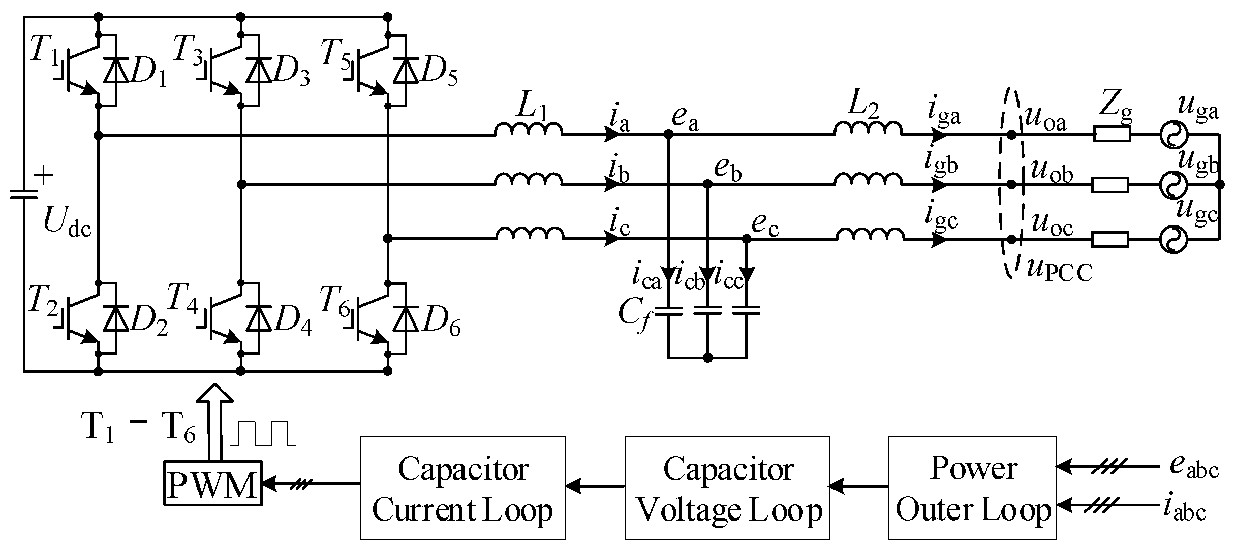
2.1. Topology Description of a VSG Grid-Connected System

Figure 1 shows the overall diagram of a VSG grid-connected system. Udc, uga/gb/gc, uoa/ob/oc, and ea/b/c are the dc bus voltage, the grid voltage, the voltage at the point of common coupling, and the capacitor voltage, respectively. ia/b/c, iga/gb/gc, and ica/cb/cc are the dc inverter-side current, the grid-side current, and the capacitor current, respectively. Cf, Zg, L1, and L2, are the filter capacitors, the grid impedance, the inverter-side inductor, and the grid-side inductor, respectively.

2.2. Control Loops Description of a VSG Grid-Connected Inverter

In Figure 1, the VSG grid-connected inverter system consists of three control loops, an outer loop: the power outer control loop; an inner loop: the capacitor voltage control loop, and the capacitor current control loop. It should be mentioned that a capacitor current is proposed in this paper, which can suppress the harmonics interaction. The specific analysis will be discussed in the following sections. The specific control diagram in Figure 1 is shown in Figure 2, where Pe, Qe, P0, and Q0 are the output active power, output reactive power, input active power, and input reactive power, respectively. Dp, Dq, J, ωn, ω0, and ω are the active droop coefficient, the reactive droop coefficient, the rotating inertia, the rated frequency, the grid frequency, and the output frequency, respectively.
The reference capacitor voltage ed_ref and eq_ref are obtained by adjusting the power outer loop. Gecd, Gecq, Gicd, and Gicq are the PI regulators of the capacitor voltage control loop and the capacitor current control loop. Since the inner loop is much faster than the outer loop, regarding the harmonic interaction issue, the effect of the outer loop is negligible. Meanwhile, in DC to AC converters, the DC side and AC side are normally decoupled. Therefore, the small-signal model regarding the issue of harmonics interaction is not considered an effect of the DC-link voltage, since they are on different time scales [25].

3. Output Impedance Model of a VSG

3.1. Output Impedance Model of a Single VSG

The impedance model is useful to analyze the stability issue; therefore, in order to obtain the output impedance model, the small signal model of a VSG grid-connected inverter is obtained, as shown in Figure 3. The relation between the input and output is shown in Equation (1). According to Equation (1), the transfer matrix is off diagonal, and the input and output are coupled, which is caused by the rotating transformation.
[ e ^ c d e ^ c q ] = [ G i d d G i d q G i q d G i q q ] [ e ^ d _ r e f e ^ q _ r e f ]
Recently, the resonance frequency range considered in most of the literature on harmonic currents has exceeded the response range of the outer loop. Therefore, the effect of the outer loop on the harmonic interaction is not considered when establishing the output impedance model in the frequency domain.
According to Figure 3, ed_ref and eq_ref are the given inputs, ud and uq are the PCC voltages affected by grid voltages, and igd and igq are the outputs. Equation (2) shows the relation among these variables, in which G is the voltage gain matrix, and Y is the output admittance matrix. G and Y can be calculated by Equation (3), in which Z represents the output impedance matrix. The expression of the admittance matrix is shown in Equations (4) and (5). The specific expressions of Ydd, Ydq, Yqd, and Yqq are represented by Equation (6).
[ i ^ g d i ^ g q ] i ^ g = [ Y d d Y d q Y q d Y q q ] Y [ G d d G d q G q d G q q ] G [ e ^ d _ r e f e ^ q _ r e f ] e ^ r e f - [ Y d d Y d q Y q d Y q q ] [ u ^ d u ^ q ] u ^
G = u e r e f | i g = 0 ,   Z = Y - 1 = u i g | e r e f = 0
Y = ( G e c G i c G i n v Z 2 + Z c - 1 Z 2 G i c G i n v + Z 2 + Z 1 Z c - 1 Z 2 + Z 1 ) ( Z 2 + Z 1 Z c - 1 Z 2 + Z 1 + Z 1 Z c - 1 + E + Z c - 1 Z 2 G i c G i n v ) - 1
where Gec, Gic, Ginv, Z1, Z2, and Zc are shown in Equation (5).
G e c = [ G e c d G e c q ] , G i c = [ G i c d G i c q ] , G i n v = [ G i n v G i n v ] Z 1 = [ s L 1 ω o L 1 ω o L 1 s L 1 ] , Z 2 = [ s L 2 ω o L 2 ω o L 2 s L 2 ] , Z c - 1 = [ s C f ω o C f ω o C f s C f ]
[ Y d d Y d q Y q d Y q q ] = [ Z q q Z d d Z q q Z d q Z q d Z d q Z d d Z q q Z d q Z q d Z q d Z d d Z q q Z d q Z q d Z d d Z d d Z q q Z d q Z q d ]
It can be found in Equation (2) that the main factors affecting the grid-side currents include Y, G, e_ref, and u. e_ref is the voltage reference, which is adjusted by the outer loop. The dynamic response time of the power outer loop is much slower than that of the inner loop; hence, the influence of the harmonic interference of the grid-connected current on the voltage reference e_ref can be ignored. In addition, the voltage gain matrix G is a unit gain in the low frequencies, indicating that the voltage gain has no influence on the output current in the low frequencies.
According to the expression of the grid-connected current in Equation (2), the output impedance model of a single VSG can be obtained, as shown in Figure 4, where Zg represents the grid impedance matrix, expressed as Equation (7).
Z g = [ Z g d d Z g d q Z g q d Z g q q ]

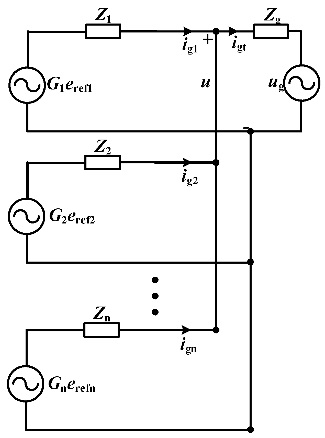
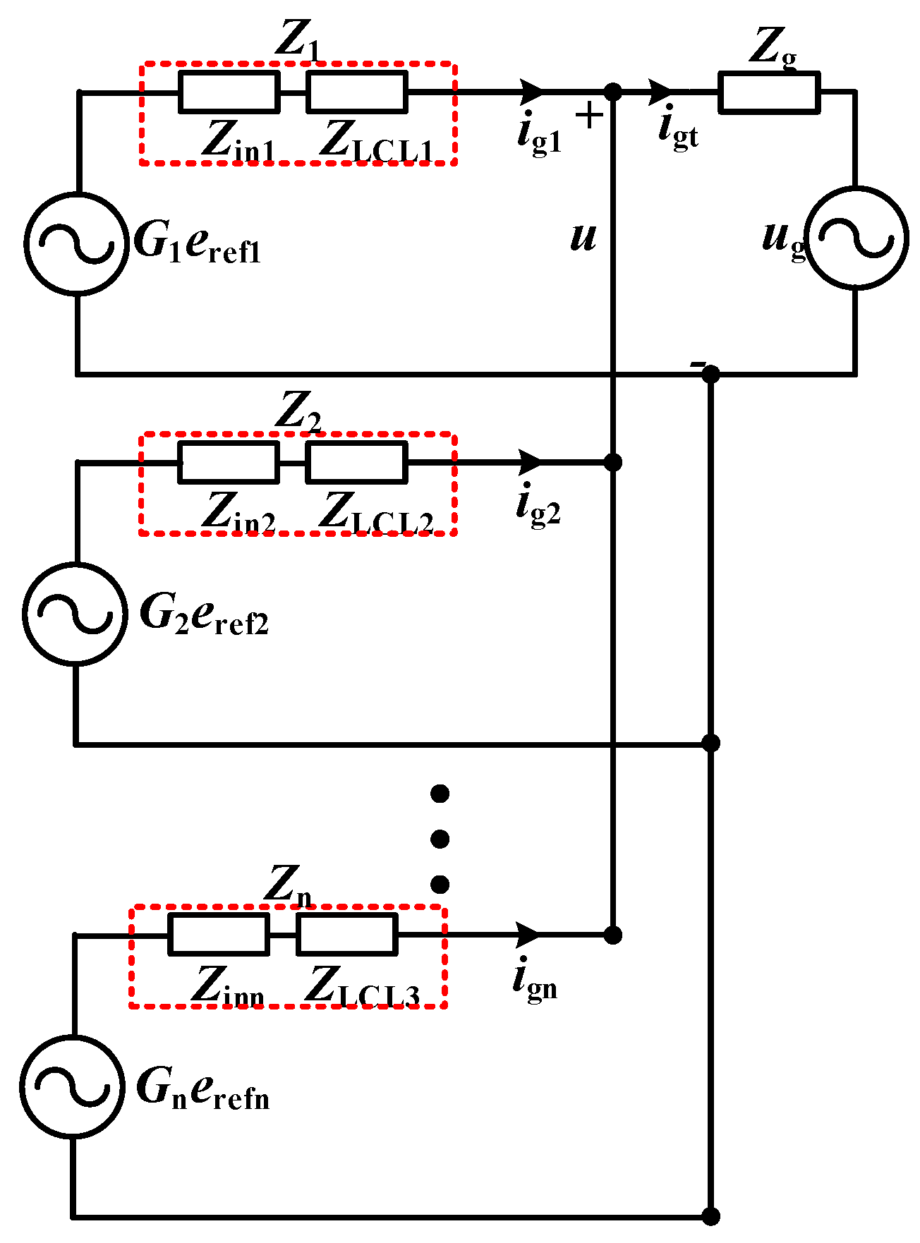
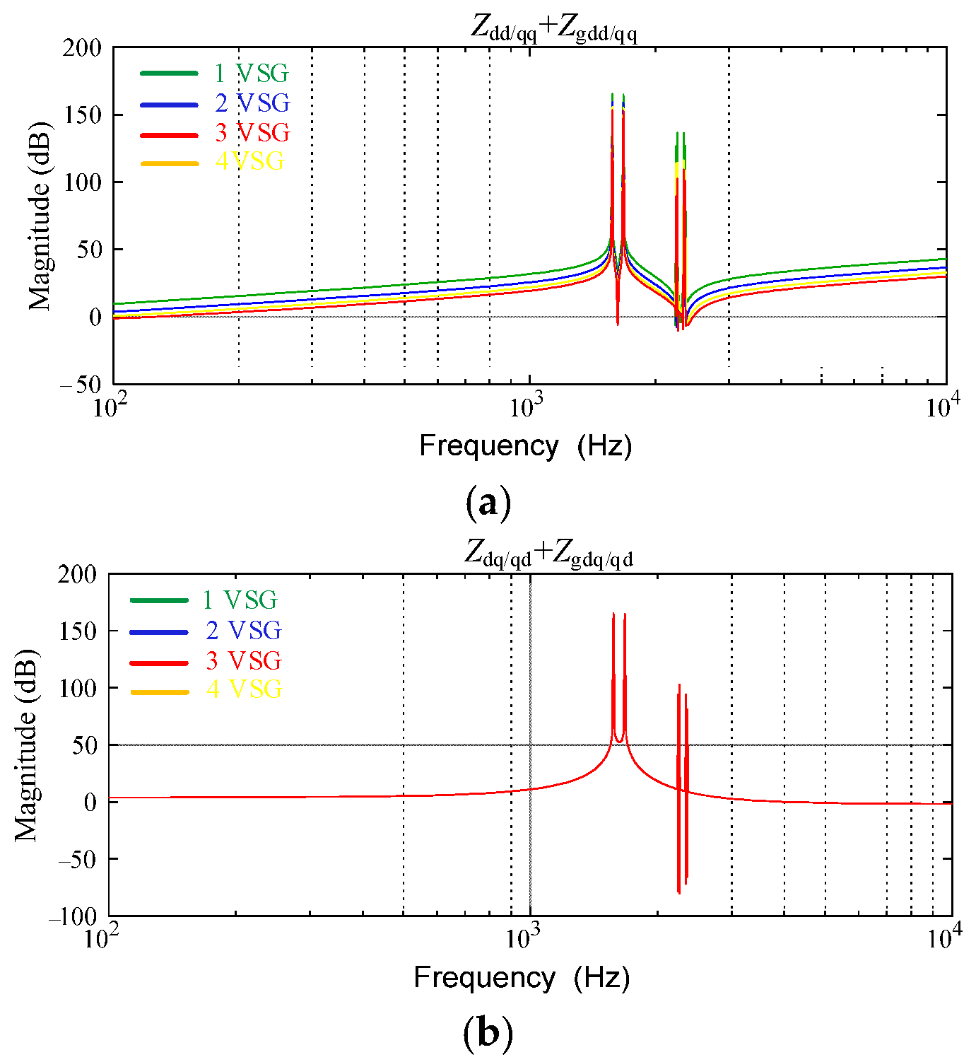
3.2. Output Impedance Model of a VSG Cluster

Furthermore, the impedance model of the VSG cluster can be obtained, as shown in Figure 5. Therefore, the grid-side current of the VSG cluster is represented by Equation (8).
i g t = Y g ( i = 1 n Y i + Y g ) - 1 i = 1 n Y i G i e r e f i ( i = 1 n Y i ) ( i = 1 n Y i + Y g ) 1 Y g u g
where Yi represents the output admittance matrix of each inverter, which is the inverse matrix of the output impedance Zi. Yg is the grid admittance impedance, and it is the inverse matrix of grid impedance Zg. When the parameters of each inverter controller and filter are identical, Equation (8) can be simplified into Equation (9).
i g t = ( Z n + Z g ) - 1 G e r e f ( Z n + Z g ) - 1 u g
Equation (9) is the relation of the output current and grid when n inverters are connected in parallel. It can be found that the total output impedance is equal to the output impedance of a single inverter divided by the number of inverters in parallel. The impedance matrix (Z/n + Zg)−1 is related to the parameters such as controllers, filters, grid impedance, and the number of the inverters in parallel. In addition, Z and Zg can be expressed as Equation (10). Therefore, Z/n + Zg can be shown as Equation (11).
c ,   Z g = [ Z g d d Z g d q Z g q d Z g q q ]
Z n + Z g = [ Z d d n + Z g d d Z d q n + Z g d q Z q d n + Z g q d Z q q n + Z g q q ]
Combining Equation (9) and Equation (11), when the value of the impedance matrix Z/n + Zg is zero or approaching zero in a certain frequency or frequency band, the harmonic current will be amplified to cause resonance at the frequency point or frequency band. Moreover, the impedance matrix Z/n + Zg can be reformulated as Equation (12).
| ( Z n + Z g ) | = ( Z d d n + Z g d d ) ( Z q q n + Z g q q ) - ( Z q d n + Z g q d ) ( Z d q n + Z g d q )
Zdd, Zqq, Zdq and Zqd are related to the controller parameters of the inner loop, and the control parameters in the d-q coordinate are generally the same. Therefore, Zdd = Zqq, Zdq = −Zqd, Zgdd = Zgqq, and Zgdq = −Zgqd. Therefore, Equation (12) can be simplified into Equation (13).
| ( Z n + Z g ) | = ( Z d d n + Z g d d ) 2 + ( Z d q n + Z g d q ) 2
To simplify the expressions of Zdd and Zqq, they can be defined as Equation (14).
Z d d = i = 0 n a i s n i j = 0 n b j s n j ,   Z d q = i = 0 n c i s n i j = 0 n d j s n j
Furthermore, the grid impedance can be described by Equation (15). Therefore, Equation (13) can be specifically expressed as Equation (16).
Z g = [ R g + s L g ω L g ω L g R g + s L g ]
| ( Z n + Z g ) | = ( i = 0 n a i s n i n j = 0 n b j s n j + R g + s L g ) 2 + ( i = 0 n c i s n i n j = 0 n d j s n j + ω L g ) 2
If Equation (16) has a zero point in the right half plane of the frequency domain, there is a certain frequency point where the value of Equation (16) is zero, indicating a resonance point in the system. In addition, Equation (16) is a function of the inner-loop controller and the grid impedance, as reformulated in Equation (17). Therefore, the characteristics of the harmonic interaction between the clustered LCL-type VSG and the utility grid can be researched by exploring the zero-point distribution in Equation (17), relating to the inner-loop controller parameters, filter parameters, and grid impedance. It should be pointed out that at least one VSG should be connected to the grid. (n = 1,2,3…).
i = 0 n a i s n i n j = 0 n b j s n j + R g + s L g = f 1 ( G e c d q , G i c d q , L 1 , L 2 , C f , R g , L g , n ) i = 0 n c i s n i n j = 0 n d j s n j + ω L g = f 2 ( G ecdq , G i c d q , L 1 , L 2 , C f , L g , n )

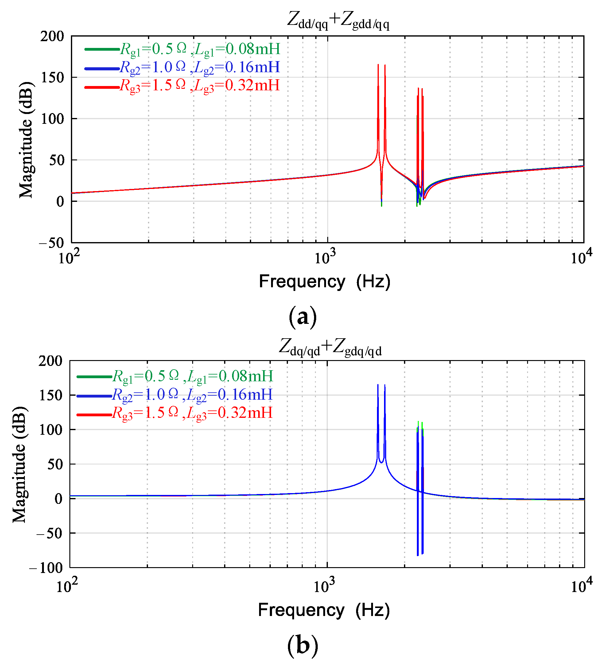
4. Parameter Sensitivity Analysis of a VSG cluster

According to Equation (17), the output impedance Z is jointly determined by the output impedance of the filter and the controller, as shown in Figure 6, where Zin1, Zin2, and Zinn are the output impedance of the inner loop under the different controller parameters, and ZLCL1, ZLCL2, and ZLCLn are the output impedance under the different filter parameters, both of which have an impact on the output impedances Z1, Z2, and Zn. Therefore, to reveal the resonant mechanism of the grid-connected VSG, the influence of filter parameters and controller parameters on the VSG output characteristics are analyzed in this section.

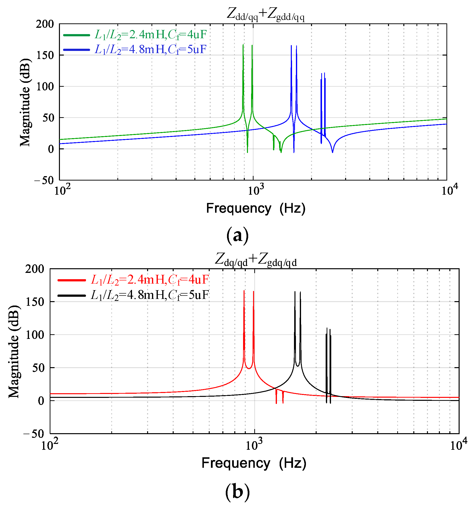
4.1. Sensitivity Analysis of Filter Parameter

To analyze the influence of the different filter parameters on the resonant characteristics and the resonant frequency distribution of a grid-connected VSG, different LCL filter parameters were selected for analysis, and the Bode plots of the output impedance were obtained, as shown in Figure 7, demonstrating the low-impedance characteristic of the VSG. In addition, the sum of the output impedance without an inner regulator (i.e., without Zin1, Zin2, and Zinn) and the grid impedance has the resonance points. Therefore, when the LCL-type inverter based on a VSG is connected to the grid, there is a risk of harmonic resonance, and the resonance point is related to the filter parameters.
In Figure 8, a VSG has a risk of harmonic resonance with the grid impedance increasing; that is, there is a resonance point between the output impedance of a VSG and the grid impedance. Moreover, with the grid impedance increasing, the resonance point offset is not obvious, indicating that the interaction with the grid is weak.
Furthermore, in Figure 9, with the number of parallel inverters increasing, the resonance point offset is also not obvious. Therefore, when the clustered LCL-type inverters based on a VSG are connected to the grid, the range of resonant frequency is basically unchanged despite the risk of harmonic resonance.
In summary, the above analysis was based on the interaction between the VSG cluster without an inner regulator and the grid. It can be found that the frequency range of the harmonic interaction between the LCL-type VSG cluster and the grid was mainly determined by the filter parameters. In addition, because of the low impedance characteristic of an LCL-type VSG, its interaction characteristic with the grid was weak. With the number of parallel VSGs increasing, the interaction characteristic between the VSG cluster and the grid was also weaker.
In fact, the changes in the inner regulator affect the VSG output impedance. Therefore, the influence of the inner-loop controllers on the output impedance characteristics are analyzed below.

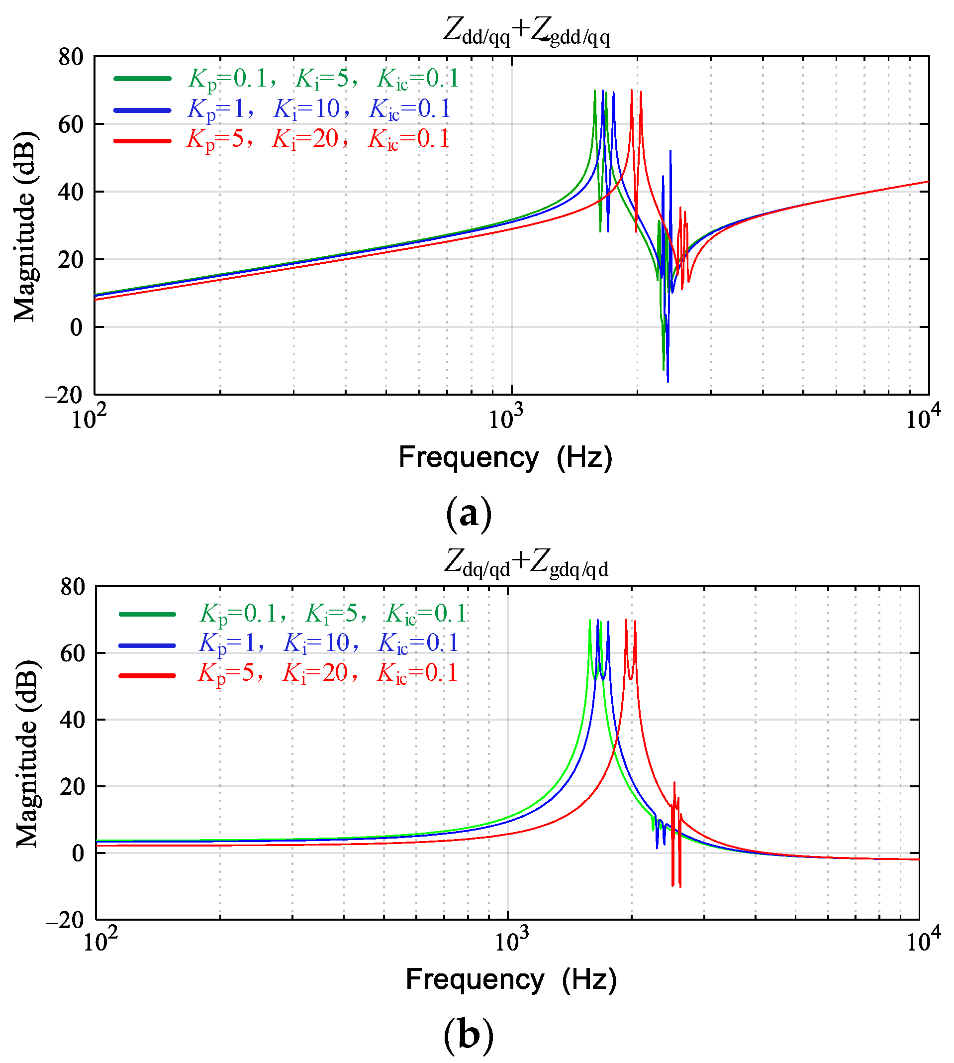
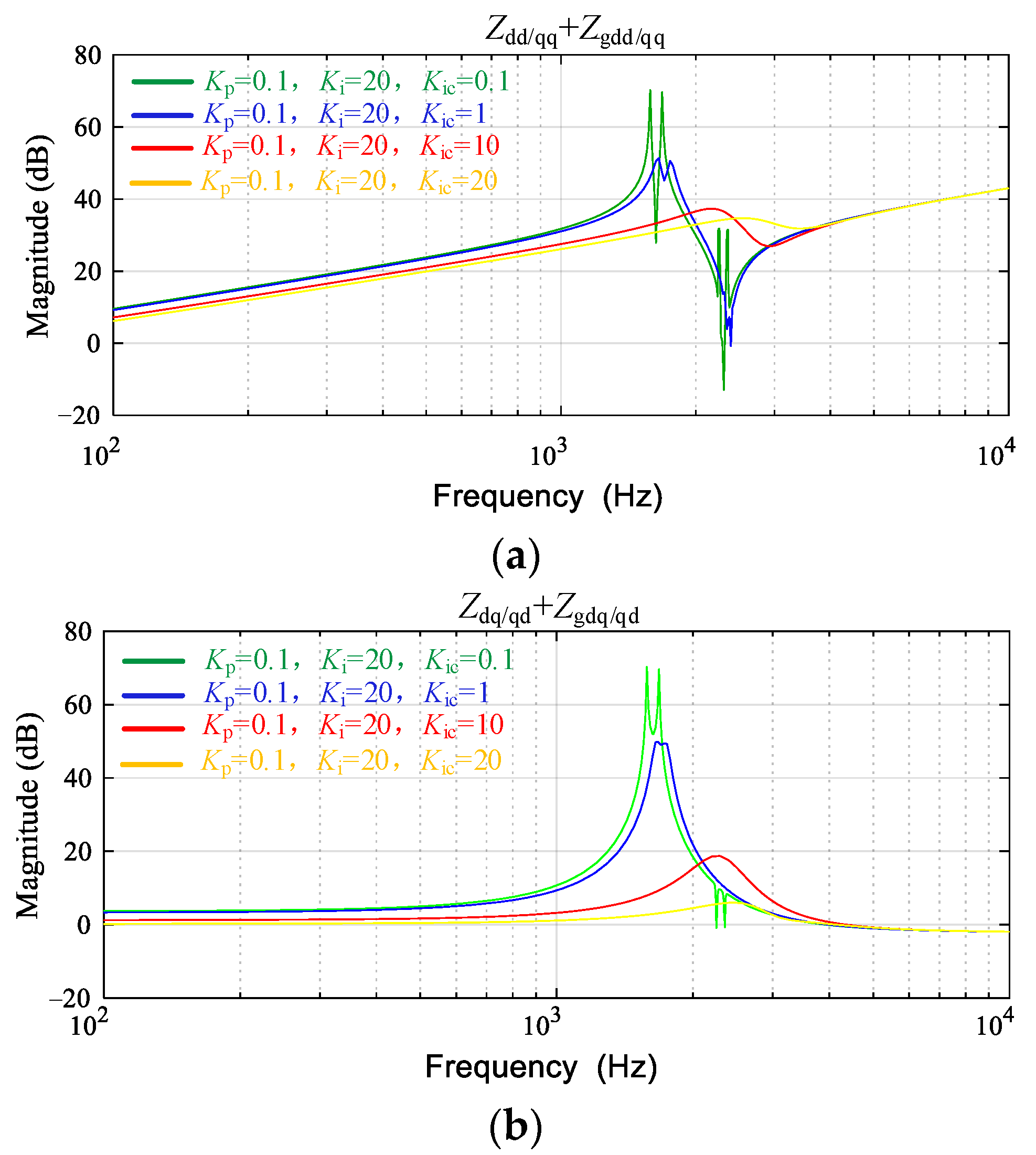
4.2. Sensitivity Analysis of the Inner-Loop Controller Parameter

In order to analyze the influence of the different inner-loop controller parameters on the output characteristics and the resonant frequency distribution of the grid-connected VSGs, different controller parameters are selected. The output impedance Bode plots are shown in Figure 10. It can be found that the capacitor voltage regulator has changed the resonance frequency, making the resonance point offsetting. When a capacitor voltage regulator design is not reasonable, the corresponding resonance point will be within the range of harmonic excitation frequency bands. Therefore, the capacitor voltage controller parameters need to be designed reasonably, to avoid the resonance point falling into the frequency range of the harmonic excitation and causing resonance. In order to investigate the sensitivity of the inner loop parameters, different values are used where Kp = 0.1, 1, and 5; Ki = 5, 10, and 20; and Kic = 0.1, 1, 10, and 20. The basic parameters used in this paper are Kp = 0.1, Ki = 20, and Kic = 20; that is, Gecd = Gecq= Kp + Ki/s (0.1 + 20/s), and Gicd = Gicq= Kic (20). The design of the parameters is based on [26].
As shown in Figure 11, the impedance Bode plots under different parameters of the capacitor current regulator are obtained. It can be seen that the capacitor current regulator mainly suppresses the amplitude of the resonant peak, while the change in the resonant frequency is small. Therefore, in order to reduce the resonance risk of an LCL-type VSG and its cluster, a capacitor current controller needs to be adopted.
As can be seen from Figure 11, with the number of parallel inverters increasing, the resonance point offset is also not obvious. Compared with the LCL-type VSG without an inner-loop controller in Figure 9, the resonance peak in Figure 12 is significantly suppressed. Therefore, when a cluster LCL-type inverter based on a VSG is connected to the grid, the resonance risk can be reduced through the inner-loop regulator. However, there is still a risk of harmonic resonance, and its resonant frequency range does not change much with the number of parallel inverters increasing.

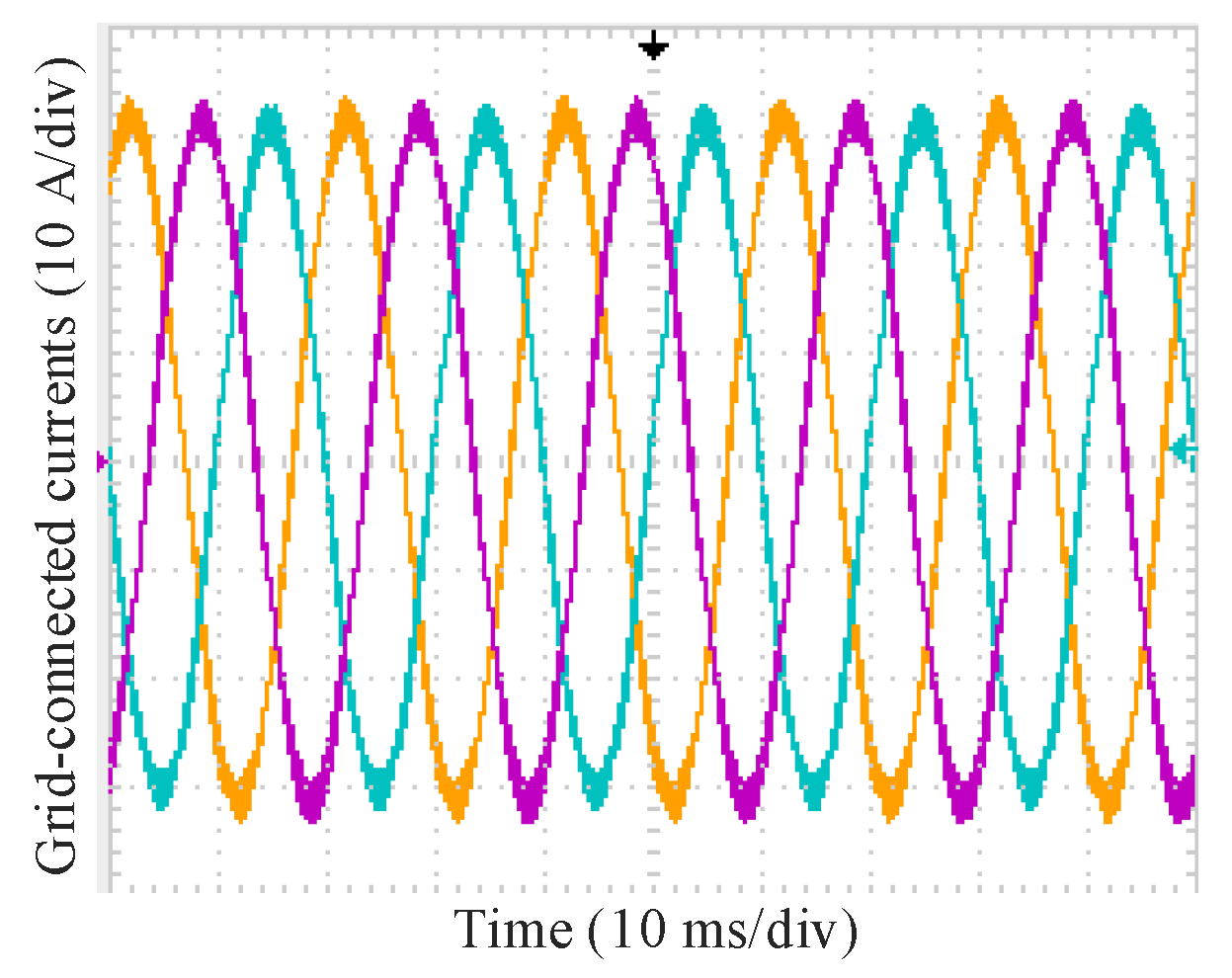
5. Simulation and Experimental Results

To verify the effectiveness of the established VSG impedance model, the harmonic interaction model between the converter and the utility grid was established based on Simulink software. The simulation parameters are shown in Table 1.
The correctness of the VSG impedance model and its cluster impedance model established in Section 3 were verified firstly. It can be seen from the time-domain simulation results in Figure 13 that the output currents of the impedance model and the switching model were identical in an ideal grid. In addition, according to the simulation results in Figure 14, the impedance model and the switching model were also identical in a distorted grid, indicating the effectiveness of the VSG impedance model.
Meanwhile, the impedance scanning method was used to compare the actual values with the theoretical calculation values, and the comparison results were obtained, as shown in Figure 15. The results showed that the output impedance of the theoretical calculation was identical to the scanned impedance, indicating the effectiveness of the impedance model of the VSG established in this paper.
Furthermore, the resonance characteristics analysis of a VSG and its cluster in Section 4.1 was verified. According to the above analysis, the resonant frequency of a VSG without an inner-loop controller is determined by the resonant frequency of the LCL-type filter. According to the parameters in Table 1, the resonant frequency of the LCL-type filter was 2.3 kHz. To intuitively reveal the resonance characteristics, 2.3 kHz, 2.1 kHz, and 2.5 kHz harmonic components were added to the grid voltage respectively after 2 s, with 1% of harmonic voltage. The simulation results were obtained, as shown in Figure 16. This indicates that the system in Figure 15a was excited by a harmonic excitation source, resulting in resonance and serious distortion of the output currents. Interestingly, in other harmonic frequency bands, the current distortion was not serious, as shown in Figure 16b,c.
As shown in Figure 17, when the three VSGs were in parallel, the resonance point was slightly offset, which was 2.25 kHz. This indicates that the resonant frequency of parallel LCL-type VSGs was mainly determined by the filter, and the resonant point changed little with the number of the clustered inverters increasing, which further demonstrates that the harmonic interaction between an LCL-type VSG and the grid is weak.
According to the analysis in Section 4.2, the resonant frequency points of a VSG can be changed by the different capacitor voltage controller parameters, but the resonant frequency band remains unchanged after the introduction of the inner-loop controller. The corresponding simulation results were obtained, as shown in Figure 18. When the parameters of the inner-loop controller were Kp = 0.1, Ki = 20, and Kic = 0.1, the resonant frequency was 2.35 kHz, as shown in Figure 18a. When Ki increased from 5 to 20, the resonant frequency was 2.3 kHz, as shown in Figure 18b.
When the parameter of the capacitor current controller Kic changed, the resonant peak was significantly suppressed. As shown in Figure 19, this indicates that the grid-side current quality was improved obviously under the same harmonic excitation, and the THD of the grid-connected currents was just 3.2%. Therefore, the capacitor current controller can effectively suppress the resonant peak of an LCL-type VSG and its cluster.
Table 2 shows that the model will be resonant when injecting the harmonics at the resonant frequency. It is shown that the established model was correct to predict the resonance in the VSG-clusters grid-connected inverters system.
Table 3 shows the comparison in terms of THD, in which it can be seen that the THD was suppressed by the capacitor current feedback loop. With capacitor current (CC) control, the THD was 3.2%, which was 10 times lower than the result without CC control. Therefore, the proposed scheme can effectively suppress the harmonics, which meets the requirements of IEEE Standard 519.
To further verify the above resonance characteristics analysis of a VSG based on the output impedance model, an experimental platform with three parallel VSGs was built in the laboratory, and the harmonic excitation was generated by a grid simulator. The experimental parameters were the same as the simulation parameters in Table 1. Figure 20 shows the experimental platform including a grid simulator (Chroma 61830) from Chroma Company (Taoyuan City, Taiwan), three grid-connected inverters, a PC, and three electronics loads. Other equipment included a digital signal processor (DSP TMS320F28335) from TI Company (Dallas, TX, USA), a current probe (CWTMini 3B) form PEM Company (Surrey, UK), and an oscilloscope (Tektronix MDO3024) from Tektronix Company (Beaverton, OR, USA). The configuration of the experiment used the grid simulator to generate three-phase voltages with high-frequency harmonics (2.3 kHz). Then, it used different control strategies to control the three VSGs in order to suppress the harmonics. As shown in Figure 21a, the current waveforms of a single VSG generated severe resonance in a polluted grid with 2.3 kHz harmonic voltage. In addition, for the three VSGs in parallel, the resonant frequency was shifted slightly to 2.25 kHz. When the 2.25 kHz harmonic excitation was injected into the grid, the system also generated resonance, as shown in Figure 21b.
After the introduction of the inner-loop controllers, especially the capacitor current inner-loop controller, the resonance peak of the LCL-type inverter based on a VSG was well suppressed, as shown in Figure 22. Therefore, for an LCL-type inverter based on a VSG, it is significant to adopt the inner-loop controller to reduce the risk of harmonic resonance.

6. Conclusions

(1)
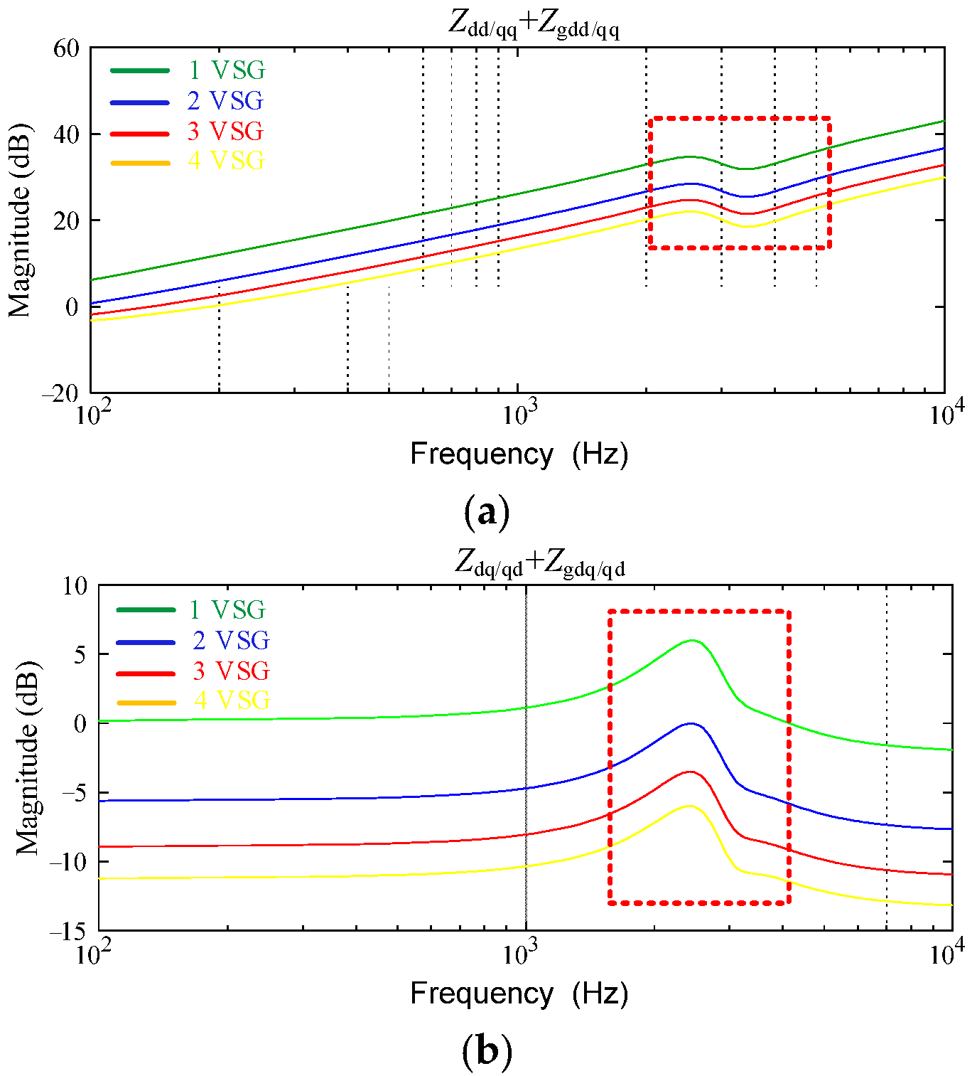
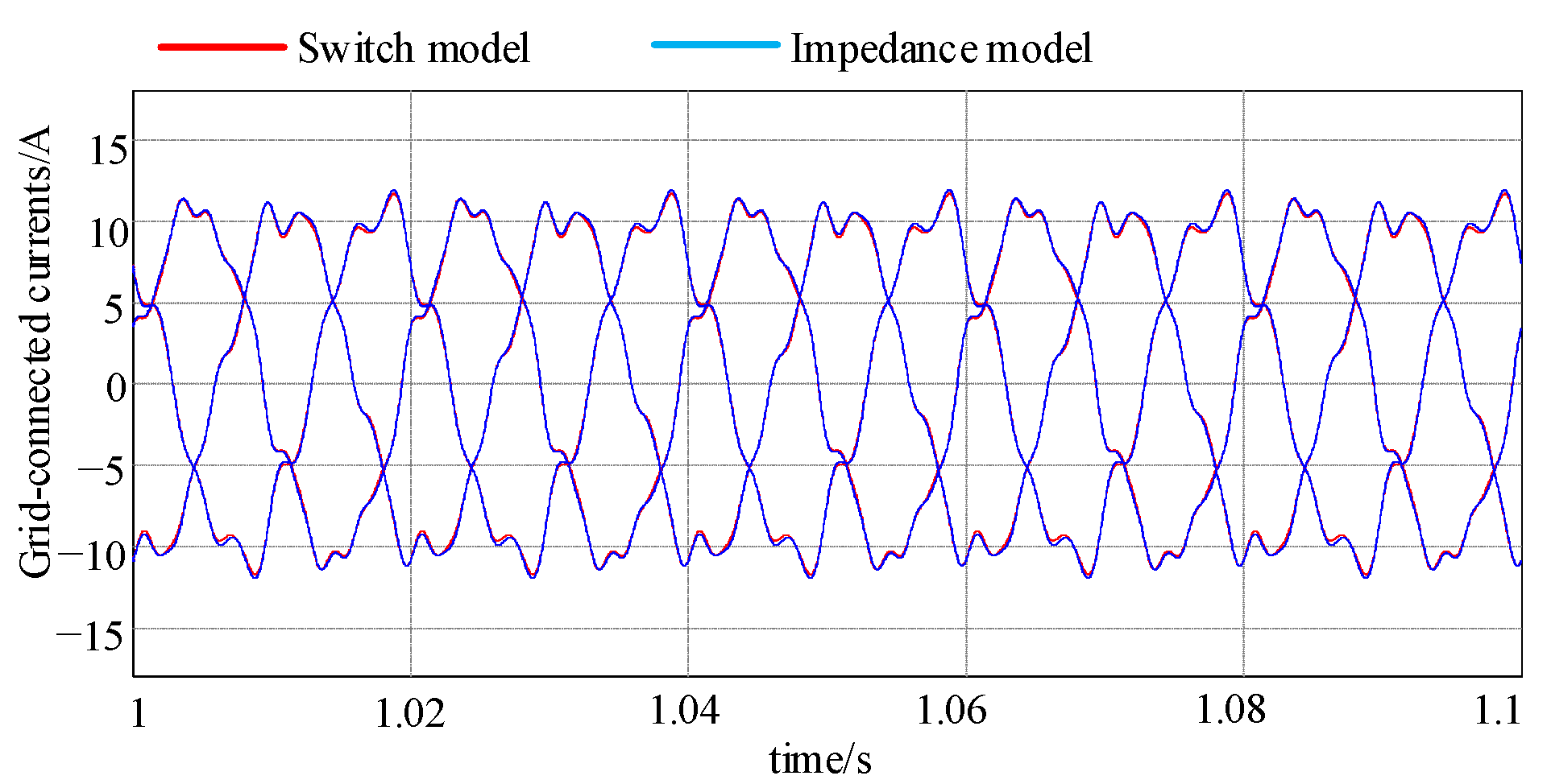
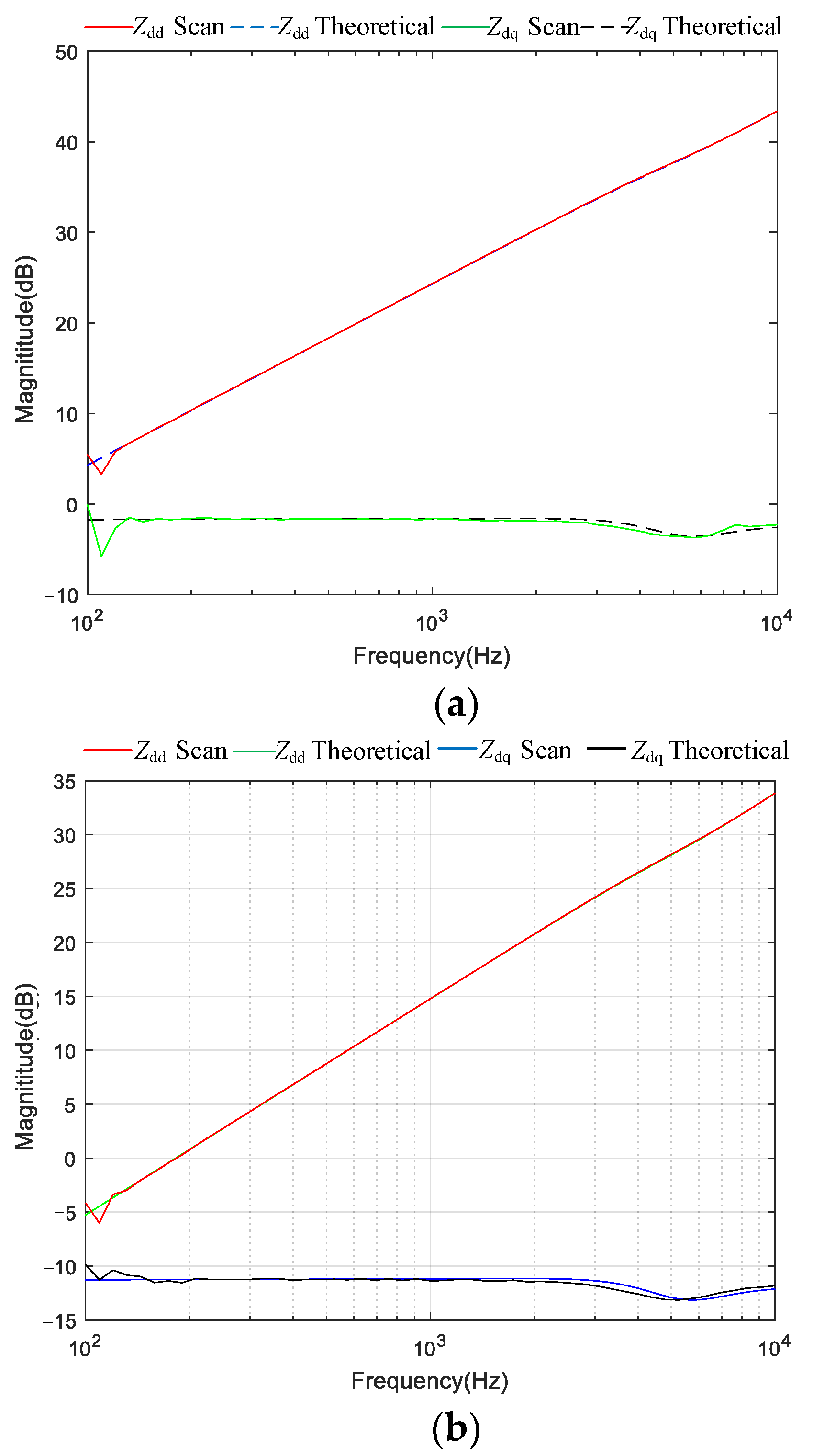
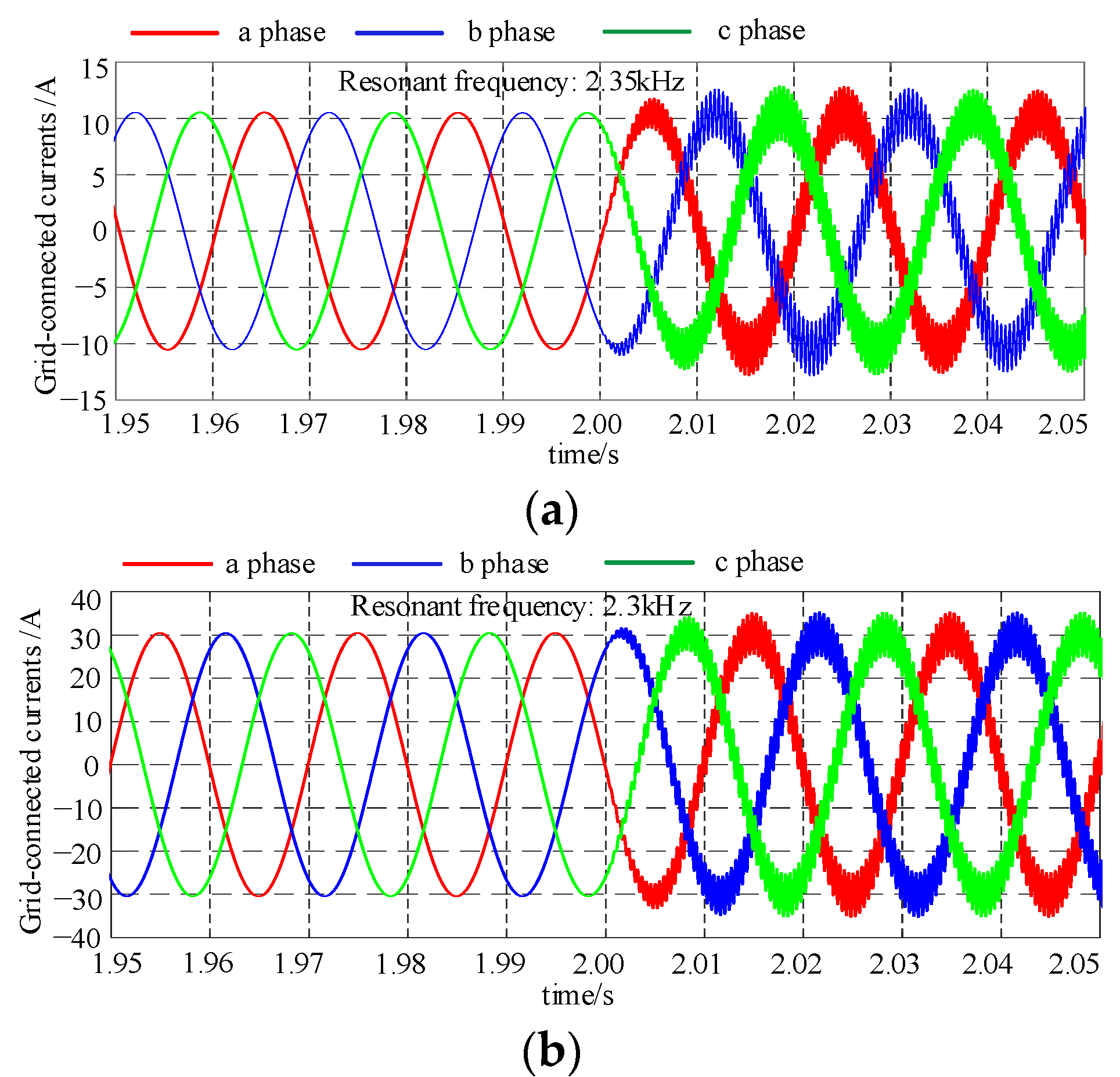
In this paper, the output impedance model of the VSG cluster was established, which revealed that the VSG-type grid-connected inverters had a resonant risk. Furthermore, the simulation and experimental results verified the effectiveness of the output impedance model.
(2)
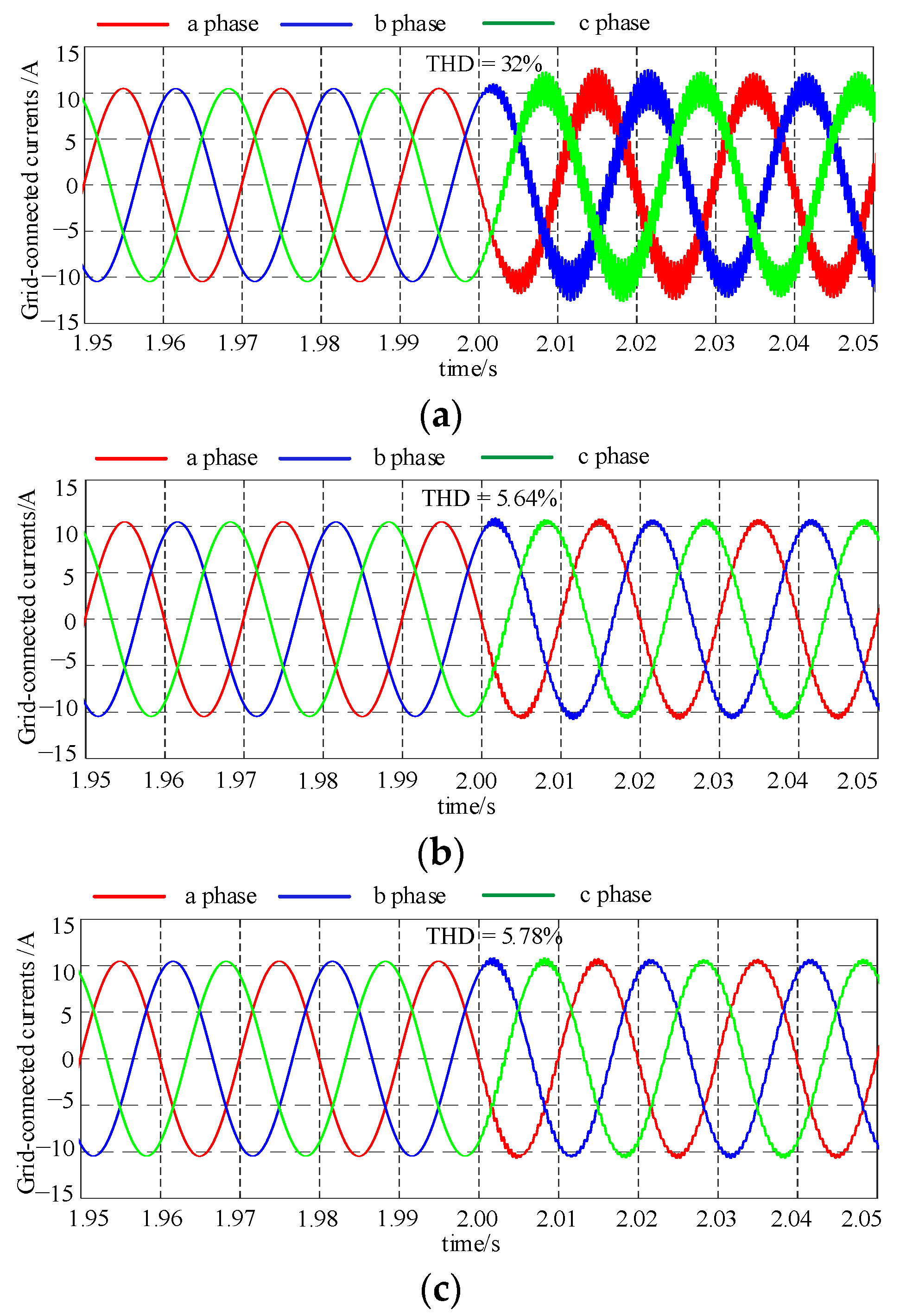
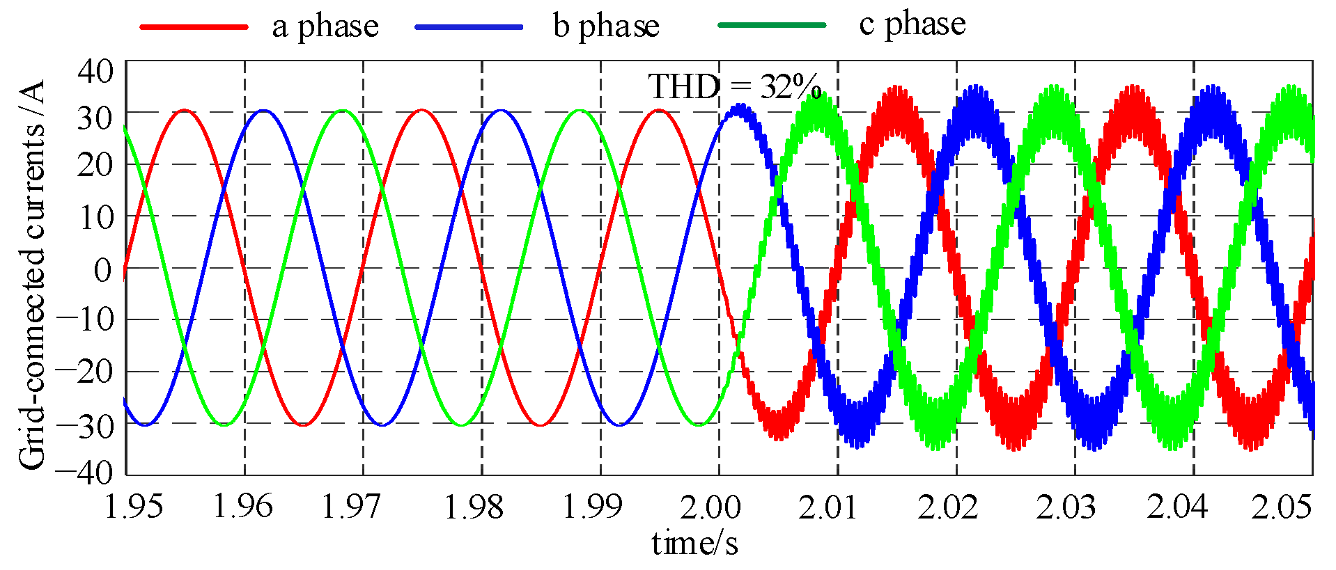
The influence of the filter parameters, controller parameters, and grid parameters on the output impedance characteristics was addressed. It was concluded that the resonant frequency of the inverter-grid system based on a VSG was mainly determined by the filter. In the experimental case, the resonant point was around 2.3 kHz when the number of grid-connected inverters increased to three.
(3)
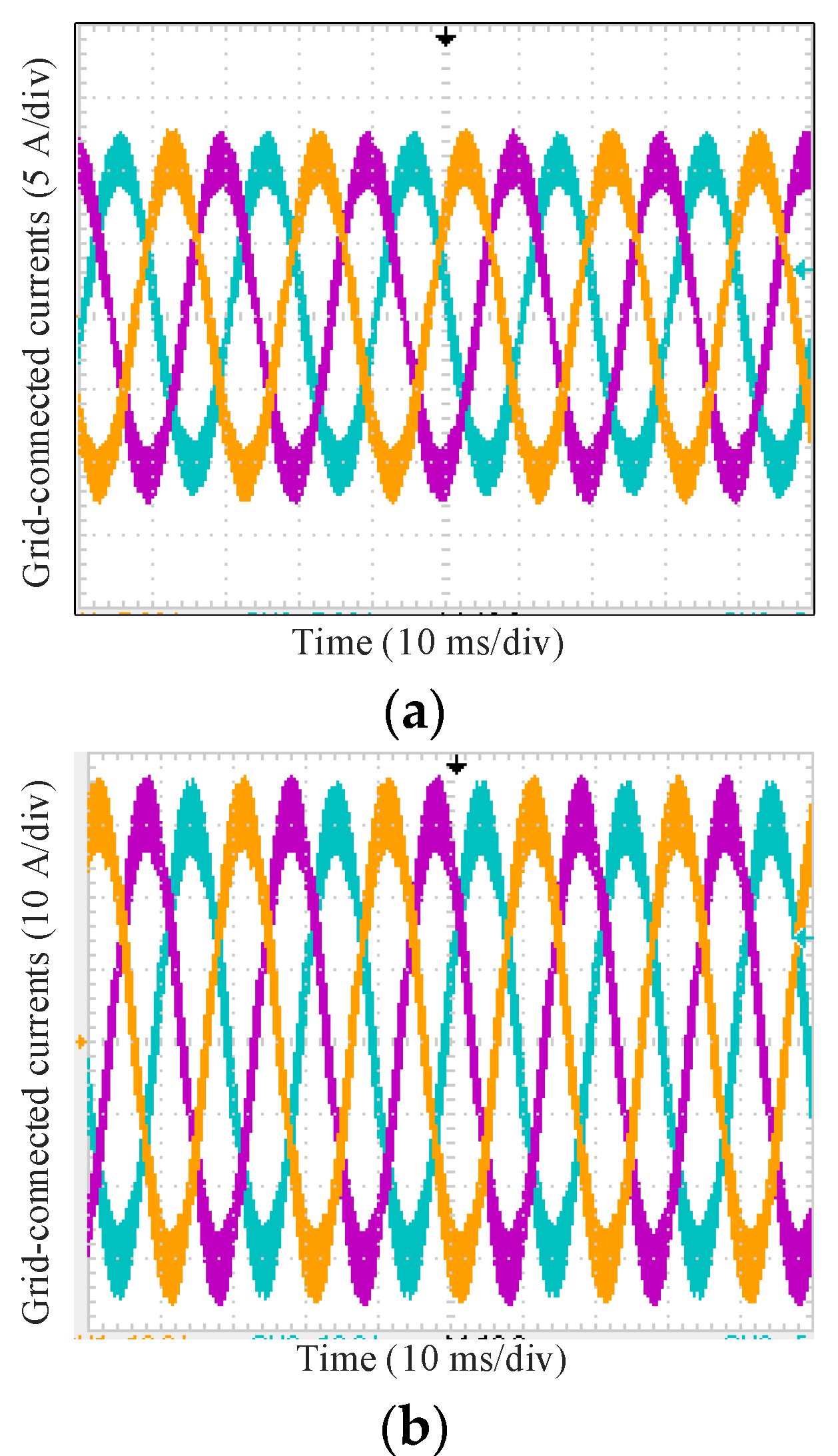
In addition, the capacitor current control for grid-connected inverters based on a VSG was proposed. With the dual-loop control strategy, the resonant peak was suppressed. Therefore, for an LCL-type grid-connected VSG cluster control, it is significant to add a capacitor current inner-loop controller to suppress the resonant peak and improve the system stability. The total harmonic distortion (THD) was reduced to 3.2%, which meets the requirements of IEEE standard 519.
(4)
Furthermore, the inverter-grid system based on a VSG presented low-impedance characteristics, indicating weak harmonic interaction characteristics. With the number of clustered VSG increasing, the weak interaction characteristics did not change. Therefore, the weak interaction characteristics are conducive for the VSG cluster to be connected to the grid.

Author Contributions

Conceptualization, L.R. and H.G.; methodology, F.W.; software, L.Z.; validation, H.G., Z.D. and F.W.; formal analysis, L.Z.; investigation, L.Z.; resources, Z.D. and F.W.; data curation, L.Z.; writing—original draft preparation, L.R.; writing—review and editing, H.G. and F.W.; visualization, L.Z.; supervision, Z.D. and F.W. All authors have read and agreed to the published version of the manuscript.

Funding

This research was funded by the National Natural Science Foundation of China, grant number 51977126.

Institutional Review Board Statement

Not applicable.

Informed Consent Statement

Not applicable.

Conflicts of Interest

The authors declare no conflict of interest.

References

  1. Hirase, Y.; Ohara, Y.; Matsuura, N.; Yamazaki, T. Dynamics Analysis Using Koopman Mode Decomposition of a Microgrid Including Virtual Synchronous Generator-Based Inverters. Energies 2021, 14, 4581. [Google Scholar] [CrossRef]
  2. Guo, J.; Chen, Y.; Wang, L.; Wu, W.; Wang, X.; Shuai, Z.; Guerrero, J.M. Impedance Analysis and Stabilization of Virtual Synchronous Generators with Different DC-Link Voltage Controllers under Weak Grid. IEEE Trans. Power Electron. 2021, 36, 11397–11408. [Google Scholar] [CrossRef]
  3. Wen, T.; Zhu, D.; Zou, X.; Jiang, B.; Peng, L.; Kang, Y. Power Coupling Mechanism Analysis and Improved Decoupling Control for Virtual Synchronous Generator. IEEE Trans. Power Electron. 2021, 36, 3028–3041. [Google Scholar] [CrossRef]
  4. Cheng, H.; Shuai, Z.; Shen, C.; Liu, X.; Li, Z.; Shen, Z.J. Transient Angle Stability of Paralleled Synchronous and Virtual Synchronous Generators in Islanded Microgrids. IEEE Trans. Power Electron. 2020, 35, 8751–8765. [Google Scholar] [CrossRef]
  5. Chen, M.; Zhou, D.; Blaabjerg, F. Active Power Oscillation Damping Based on Acceleration Control in Paralleled Virtual Synchronous Generators System. IEEE Trans. Power Electron. 2021, 36, 9501–9510. [Google Scholar] [CrossRef]
  6. Zhong, Q.-C.; Weiss, G. Synchronverters: Inverters that mimic synchronous generators. IEEE Trans. Ind. Electron. 2011, 58, 1259–1267. [Google Scholar] [CrossRef]
  7. Sun, Y.; Zhao, Y.; Dou, Z.; Li, Y.; Guo, L. Model Predictive Virtual Synchronous Control of Permanent Magnet Synchronous Generator-Based Wind Power System. Energies 2020, 13, 5022. [Google Scholar] [CrossRef]
  8. Zhong, Q.; Nguyen, P.; Ma, Z.; Sheng, W. Self-synchronised synchronverters: Inverters without a dedicated synchronisation unit. IEEE Trans. Power Electron. 2014, 29, 617–630. [Google Scholar] [CrossRef]
  9. Hu, Y.; Shao, Y.; Yang, R.; Long, X.; Chen, G. A Configurable Virtual Impedance Method for Grid-Connected Virtual Synchronous Generator to Improve the Quality of Output Current. IEEE J. Emerg. Sel. Top. Power Electron. 2020, 8, 2404–2419. [Google Scholar] [CrossRef]
  10. Shi, K.; Song, W.; Ge, H.; Xu, P.; Yang, Y.; Blaabjerg, F. Transient Analysis of Microgrids with Parallel Synchronous Generators and Virtual Synchronous Generators. IEEE Trans. Energy Convers. 2020, 35, 95–105. [Google Scholar] [CrossRef]
  11. Wu, H.; Ruan, X.; Yang, D.; Chen, X.; Zhao, W.; Lv, Z.; Zhong, Q.-C. Small-Signal Modeling and Parameters Design for Virtual Synchronous Generators. IEEE Trans. Ind. Electron. 2016, 63, 4292–4303. [Google Scholar] [CrossRef]
  12. Deng, J.; Xia, N.; Yin, J.; Jin, J.; Peng, S.; Wang, T. Small-Signal Modeling and Parameter Optimization Design for Photovoltaic Virtual Synchronous Generator. Energies 2020, 13, 398. [Google Scholar] [CrossRef] [Green Version]
  13. Arco, D.; Suul, J. Equivalence of virtual synchronous machines and frequency-droops for converter-based microgrids. IEEE Trans. Smart Grid 2014, 5, 394–395. [Google Scholar] [CrossRef]
  14. Alipoor, J.; Miura, Y.; Ise, T. Power system stabilization using virtual synchronous generator with alternating moment of inertia. IEEE J. Emerg. Sel. Top. Power Electron. 2015, 3, 451–458. [Google Scholar] [CrossRef]
  15. Zheng, T.; Chen, L.; Wang, R.; Li, C.; Mei, S. Adaptive damping control strategy of virtual synchronous generator for frequency oscillation suppression. In Proceedings of the 12th IET International Conference on AC and DC Power Transmission (ACDC), Beijing, China, 28–29 May 2016. [Google Scholar]
  16. Wang, F.; Zhang, L.; Feng, X.; Guo, H. An adaptive control strategy for virtual synchronous generator. IEEE Trans. Ind. Appl. 2018, 54, 5124–5133. [Google Scholar] [CrossRef]
  17. Shi, R.; Zhang, X.; Liu, F.; Xu, H.; Tao, L. A dynamic voltage transient suppression control strategy for microgrid inverter. IEEE Trans. Ind. Electron. 2016, 63, 4292–4303. [Google Scholar] [CrossRef]
  18. Zhu, K.; Sun, P.; Zhou, L.; Du, X.; Luo, Q. Frequency-Division Virtual Impedance Shaping Control Method for Grid-Connected Inverters in a Weak and Distorted Grid. IEEE Trans. Power Electron. 2020, 35, 8116–8129. [Google Scholar] [CrossRef]
  19. Shi, R.; Zhang, X.; Liu, F.; Xu, H.; Hu, C.; Cao, W. Multiloop control strategy for virtual synchronous generator using only output voltage feedback. J. Power Supply 2017, 15, 17–25. [Google Scholar]
  20. Shi, R.; Zhang, X.; Liu, F.; Xu, H.; Hu, C.; Yu, Y.; Ni, H. A control strategy for unbalanced and nonlinear mixed loads of virtual synchronous generators. Proc. CSEE 2016, 36, 6086–6095. [Google Scholar] [CrossRef]
  21. Wu, W.; Zhou, L.; Chen, Y.; Luo, A.; Zhou, X.; He, Z.; Yang, L.; Liu, J. Stability comparison and analysis between the virtual synchronous generator and the traditional grid-connected inverter in the view of sequence impedance. Proc. CSEE 2019, 39, 1411–1421. [Google Scholar]
  22. Wu, W.; Chen, Y.; Zhou, L.; Luo, A.; Zhou, X.; He, Z.; Yang, L.; Xie, Z.; Liu, J.; Zhang, M. Sequence Impedance Modeling and Stability Comparative Analysis of Voltage-Controlled VSGs and Current-Controlled VSGs. IEEE Trans. Ind. Electron. 2019, 66, 6460–6472. [Google Scholar] [CrossRef]
  23. Wang, S.; Liu, Z.; Liu, J. Modeling of d-q small-signal impedance of virtual synchronous generator. In Proceedings of the 2018 IEEE International Power Electronics and Application Conference and Exposition (PEAC), Shenzhen, China, 4–7 November 2018; pp. 1–6. [Google Scholar]
  24. Wang, F.F.; Duarte, J.L.; Hendrix, M.A.M.; Ribeiro, P. Modeling and Analysis of Grid Harmonic Distortion Impact of Aggregated DG Inverters. IEEE Trans. Power Electron. 2011, 26, 786–797. [Google Scholar] [CrossRef]
  25. Shuai, Z.; Li, Y.; Wu, W.; Tu, C.; Luo, A.; Shen, J.Z. Divided DQ Small-Signal Model: A New Perspective for the Stability Analysis of Three-Phase Grid-Tied Inverters. IEEE Trans. Ind. Electron. 2019, 66, 6493–6504. [Google Scholar] [CrossRef]
  26. Rathnayake, D.B.; Razzaghi, R.; Bahrani, B. Generalized virtual synchronous generator control design for renewable power systems. IEEE Trans. Sustain. Energy 2022, 13, 1021–1036. [Google Scholar] [CrossRef]
Figure 1. Overall diagram of a VSG grid-connected inverter system.
Energies 15 03490 g001
Figure 2. Control loop diagram of a VSG grid-connected inverter system.
Energies 15 03490 g002
Figure 3. System diagram of inner loop.
Energies 15 03490 g003
Figure 4. Impedance model of a single VSG. (a) Composite impedance model in the d-q coordinate of a single VSG; (b) Decomposition impedance model in the d-q coordinate of a single VSG.
Energies 15 03490 g004
Figure 5. Impedance model of clustered inverters based on VSG.
Energies 15 03490 g005
Figure 6. Impedance model of a VSG cluster.
Energies 15 03490 g006
Figure 7. Impedance Bode plots under different parameters of a filter without an inner regulator. (a) Impedance characteristics on the main diagonal. (b) Impedance characteristics on the subdiagonal.
Energies 15 03490 g007
Figure 8. Impedance Bode plots under different parameters of the grid without an inner regulator. (a) Impedance characteristics on the main diagonal. (b) Impedance characteristics on the subdiagonal.
Energies 15 03490 g008
Figure 9. Impedance Bode plots under different inverters paralleled without an inner regulator. (a) Impedance characteristics on the main diagonal. (b) Impedance characteristics on the subdiagonal.
Energies 15 03490 g009
Figure 10. Impedance Bode plots under different parameters of the capacitor voltage regulator. (a) Impedance characteristics on the main diagonal. (b) Impedance characteristics on the subdiagonal.
Energies 15 03490 g010
Figure 11. Impedance Bode plots under different parameters of a capacitor current regulator. (a) Impedance characteristics on the main diagonal. (b) Impedance characteristics on the subdiagonal.
Energies 15 03490 g011
Figure 12. Impedance Bode plots under different paralleled inverters. (a) Impedance characteristics on the main diagonal. (b) Impedance characteristics on the subdiagonal.
Energies 15 03490 g012
Figure 13. Simulation results of the current in the switch model and impedance model in an ideal grid.
Energies 15 03490 g013
Figure 14. Simulation results of the current in the switch model and impedance model in a distorted grid.
Energies 15 03490 g014
Figure 15. Comparison results of the output impedance in theory and calculation. (a) Comparison results of the output impedance of a single VSG. (b) Comparison results of the output impedance of three VSGs.
Energies 15 03490 g015
Figure 16. Current waveform of a single VSG injected with 2.3 kHz harmonic voltage. (a) A harmonic voltage of 2.3 kHz injected. (b) A harmonic voltage of 2.1 kHz injected. (c) A harmonic voltage of 2.5 kHz injected.
Energies 15 03490 g016
Figure 17. Current waveform of three VSGs with 2.25 kHz harmonic voltage injected.
Energies 15 03490 g017
Figure 18. Current waveform under different parameters of a capacitor voltage regulator. (a) Kp = 0.1, Ki = 5, and Kic = 0.1. (b) Kp = 0.1, Ki = 20, and Kic = 0.1.
Energies 15 03490 g018
Figure 19. Current waveform under different parameters of the capacitor current regulator (Kp = 0.1, Ki = 5, and Kic = 20).
Energies 15 03490 g019
Figure 20. Experimental platform.
Energies 15 03490 g020
Figure 21. Current waveform of a VSG injected harmonic voltage in a weak grid. (a) Current waveform of a single VSG. (b) Current waveform of three VSGs.
Energies 15 03490 g021
Figure 22. Current waveform of a VSG with an inner regulator.
Energies 15 03490 g022
Table 1. Parameters of an LCL-type three-phase inverter.
ParameterValueParameterValue
Grid voltage220 VProportional coefficient of capacitor voltage Kp0.1
Grid frequency50 HzIntegral coefficient of capacitor voltage Ki20
DC bus voltage800 VProportional coefficient of capacitor current Kic20
Inverter-side inductor2.4 mHRotational inertia0.057
Grid-side inductor2.4 mHDroop coefficient1592
Filter capacitor4 μFGrid resistance0.5 Ω
Switching frequency16 kHzGrid inductor0.08 mH
Table 2. Comparison in terms of injected harmonics.
Injected HarmonicsTHD
2.1 kHz5.64%
2.3 kHz32%
2.5 kHz5.78%
Table 3. Comparison in terms of control strategy.
Without CC ControlWith CC Control
THD32%3.2%
Publisher’s Note: MDPI stays neutral with regard to jurisdictional claims in published maps and institutional affiliations.

