Article

Static and Dynamic Simulation of an Induction Motor Using Matlab/Simulink

Department of Electrical Engineering, Tshwane University of Technology, Emalahleni 1034, South Africa
*
Author to whom correspondence should be addressed.
Energies 2022, 15(10), 3564; https://doi.org/10.3390/en15103564
Submission received: 6 March 2022 / Accepted: 18 April 2022 / Published: 12 May 2022
(This article belongs to the Special Issue Performance of Induction Machines)

Abstract

:
Industries are adequately configured with the operational devices that are required to develop induction motors. Engineers should precisely comprehend the kind of equipment that is constructed, as with every other production system, and should start by having the goal in their perspective. An adaptable simulation of an induction motor with a protective scheme is presented. The adaptable simulation assists engineers in accurately designing motors that meet all protective standards for certain purposes. This work achieved simulations of induction motors in stable and unstable conditions. An extensive study was performed to determine the optimum design of an induction motor. This paper attempts to provide engineers with a thorough grasp of the adaptable modelling of an induction motor. In this work, a direct dq0-direct axis algorithm is presented to implement both static and dynamic modelling of a three-phase induction machine due to possible faults and high-performance requirements in induction machines. The proposed algorithm was tested against several conventional methods, and it was observed that under the stable condition of the machinery, the proposed algorithm could remove any developing faults. This conserves time and minimises the labour required of the operator, which makes the proposed algorithm more efficient. Furthermore, the machine is demonstrated in a steady-state performance with respect to the current, active power, efficiency, reactive power, power factor, and speed when the torque loads range from 0 to 125% of its nominal torque. The transient behaviour of the machine was shown through the current, electromagnetic torque, electromagnetic torque versus speed, and speed under no-load, half-load (50%), and full-load (100%) conditions. Finally, the results of the proposed technique were compared to the results of the measured parameters. It was observed that when the load changed from a half load (50%) to a full load (100%), then the supply voltage was suddenly halved with the load at full load (100%). It was observed that the proposed algorithm provides accurate estimates with a deviation of not more than +/−2% from the measured parameters.

1. Introduction

The most popular motors utilized in economic mobility automation applications and primary-supply residential electrical consumables are AC induction machines. The key benefits of AC induction machines are their simplicity and robust construction, competitive prices, minimal servicing, and straightforward integration into an AC power supply. There are many different kinds of AC induction machines accessible in the industry. Several machines are appropriate for various functions [1]. However, AC induction machines are convenient to construct compared to DC machines. Controlling the rpm and torque in different varieties of AC induction machines requires a deeper grasp of the configuration and features of such motors. However, DC motors are efficient at commencing and moderating speed. Such machines have a great torque concentration [2]. A DC machine works quietly and has a hugely variable speed. The electromagnetic disturbance is minimal, and the overcurrent or inrush tolerance is substantial. The construction or assembly of a DC machine is one of its limitations. The commutator and the brush [3] have a rubbing connection, resulting in sparks and mechanical degradation. As a result, DC machines possess a comparatively limited operating lifespan, requiring a high service expense. This also casts uncertainties about the system’s durability and safety. As a result, the usage of DC machines in some industrial applications is restricted nowadays [4].
Over the years, motors have revolutionised the mining and automation industry. Processes such as hoisting conveyor belt systems for moving minerals, e.g., gold, coal, diamonds, etc., from underground and opencast mines, depend largely on the utilisation of induction motors [5]. Thus, for the reliable operation of these machines, proper protection needs to be implemented for safe operation under load conditions. Any malfunction of an induction motor can be described as an electrical fault, environmental factor, or mechanical breakdown. Rotor bearings could result in overheating, wear, and tear due to mechanical stresses [6]. Drawing enormous magnitudes of currents ensure high temperatures. Modelling an induction motor is somewhat complex, stemming from its non-linear behaviour triggered by electromagnetic exhaustion and the significant temperature influence from the synchronous motor settings [7].
Furthermore, the shaft time constant of an induction motor can change due to rotor heat. Such characteristics render the mathematical modelling of induction motors somewhat insurmountable. Most researchers use simplified models that do not consider the factors mentioned above. Production of these machines is imperative and requires urgency in reproduction during their idle state [8].
Chitra and Prabhakar [9] presented a simulation of an induction machine by utilising the fuzzy logic approach. The authors applied the approach in their study in order to regulate the velocity of an induction machine to obtain the optimum torque with the least amount of loss. They used the field-oriented control approach to create a fuzzy logic controller that enables improved control of motor torque with greatly variable performance. Their simulated design was evaluated by utilising multiple Matlab toolboxes. They observed that the induction motor’s efficiency increased in stable conditions. The results show that the suggested speed regulator was efficient and reliable.
Elnaghi et al. [10] proposed using a genetic algorithm (GA) to process experimental loads on an inductive machine. The principle of predicting motor parameters from testing data was demonstrated using a genetic algorithm-based technique. The specifications were determined using typical no-load and blocked rotor experiments. The cost equation—the graded sum of the stator currents and rotor velocity—was studied and improved for various motor parameter values. The impact of differential equations on the estimates was also shown. The estimated speed and torque parameters from the mathematical equation were compared to the experimental findings, and both exhibited a strong connection, proving the validity of the mathematical equation and the genetic algorithm method for improvement.
Sadasivan and Mammen [11] applied the same algorithm to obtain parameters that linked the proposed technique and the loading of the electric motor using the evaluation function. They used the genetic algorithm on three separate situations of simulated loading and found that the outcomes were superior in terms of the overall losses induced by the motor. The authors’ technique proved to be effective in terms of parameter estimation.
Jirdehi and Rezaei [12] presented a simulation of an induction motor by utilising an artificial neural network (ANN) and an adaptive neuro-fuzzy inference system (ANFIS) to investigate variables that are often difficult to obtain. They used both methods to test 20 induction motors of varying power outputs. The experimental results consisted of the starting torque, current, maximum torque, full-load slip, efficiency, rated active power, and reactive power. The authors compared the findings produced by the proposed ANN and ANFIS models and the practical results. They discovered a good relationship between the projected values and the practical data. However, the proposed ANFIS model was more precise than the proposed ANN model.
Keerthipala et al. [13] explained the ANN algorithm and how it may be used to monitor an induction motor’s torque and speed regulation using linear and non-linear models. The authors reported that the linear observer approach is simple to apply in real-time; however, it does not accurately estimate the rotor and vector angle since the induction machine generally works in the saturated region. The non-linear observer approach considers the impact of the magnetic saturation of the induction machine; however, it cannot be practically applied using conventional techniques because estimating the angle requires too much time. Their suggested technique compensates for the effect of saturation and estimates the angle in a few milliseconds, which is well within the real-time limit.
This study presents an adaptable simulation of an induction motor with a downstream protective scheme [9]. In this work, a direct dq0-direct axis algorithm is presented to implement both static and dynamic modelling of a three-phase induction machine due to possible faults and high-performance requirements in induction machines. The proposed algorithm was tested against several conventional methods, and it was observed that under a stable condition of the machinery, the proposed algorithm could remove any developing faults. This conserves time and minimises the labour required of the operator, which makes the proposed algorithm more efficient. Furthermore, the machine is demonstrated in a steady-state performance with respect to current, active power, efficiency, reactive power, power factor, and speed when the torque loads range from 0 to 125% of its nominal torque. The transient behaviour of the machine was shown through the current, electromagnetic torque, electromagnetic torque versus speed, and speed under no-load, half-load (50%), and full-load (100%) conditions. Finally, the proposed technique was compared to the results of the measured parameters. It was observed that when the load changed from half load (50%) to full load (100%), the supply voltage was suddenly halved with the load at full load (100%). It was observed that the proposed algorithm provides accurate estimates with a deviation of not more than +/−2% from the measured parameters.

2. Problem Statement

An induction motor is a complex machine to design and practically implement. Today, a vast majority of software is used by different manufacturing institutions to simulate the machine before the design is implemented. However, an induction motor’s dynamic model is usually implemented in dq0-direct, quadrature, and zero-sequence axes. A static and dynamic motor model’s implementation is a mathematical representation; this strategy eliminates human error, enables designs of the utmost performance, and provides highly efficient induction motors. This work implements both static and dynamic modelling of a three-phase induction machine due to possible faults and high-performance requirements for induction machines. Using the direct dq0-direct axis method, the dynamic model’s differential equations were first derived and implemented in Matlab/Simulink; their performance was assessed in the steady-state.

3. Objectives of the Research

Induction motors help companies run their operations efficiently. It is imperative to extend studies that enhance the performance and accuracy of the designs for these organisations. The objectives of this work are to conduct comprehensive modelling of induction motors and [14]:
  • To contribute to the development of induction motor models and protection systems.
  • To simulate an adaptable simulation of a three-phase induction motor in Matlab/Simulink.
  • To accurately size the motor parameters and increase performance thereof.
  • To implement a dq0-axis reference frame modelling technique of a rotating machine.
  • To implement a feeder protection system for the machine during its steady operation.

4. Methodology

To comprehend and engineer vector-controlled drives [15], an adaptable simulation of the induction machine that is responsive to operation and safety needs to be defined. Since every control must face possible changes and faults, the adaptable simulation of a motor is argued to be an imitation of an actual factory. Nonetheless, the simulation must include the significant factor impacts that emerge throughout steady-state and transient-state events. It should also be applicable for future modifications in supply voltages and currents. Due to the precision and convenience of the space vector and phasor hypothesis, such a simulation should be produced using this hypothesis and the two-axis principle [16] of synchronous generators. All of the techniques, as well as the simulations of induction motors, are discussed and criticised accordingly in this paper, along with the proposed dq 0 axis reference frame strategy.

5. Simulations of Induction Motors

Algorithms for the regulation of motors with great velocity and performance are required in spinning machinery and electrical cars. Iron loss (ILS) influences flux measurement, variable detection, actual torque, and acceleration control. Motor losses are an essential measure of the simulation variables [17]. The models of induction motors considered in this state-of-the-art literature survey are discussed in line with the following criteria:
  • Two-pole, three-phase windings are symmetrical.
  • The slotting impacts are considered.
  • Iron losses are not disregarded.
  • The conductivity of the iron elements is limitless.
  • The magnetisation in the airgap is circular.
  • The stator and rotor windings are coordinated as a single and multi-turn full-pitch coil located on opposite sides of the air gap.
The dynamic models may be split into two major sections: the Γ Model and the Loss Model.

5.1. Γ Model

Several evaluations of three-phase induction motors have employed a traditional linear machinery design, which is generally in the internal and reciprocal inductances of the well-known Γ type of equivalent circuit [5,18]. Such a model is considerably more complicated than is required for a linear assessment. However, it is insufficient for usage when machine characteristics vary, such as when the rotor time changes with heat and reciprocal inductances are altered whenever the machine is overloaded. The inverse Γ model, as indicated in Figure 1, is very useful for learning and analysing vector control mechanisms [18], so it reduces complications when compared to the T-model. Once the machinery settings are altered, it then becomes a non-linear system. The extended Kalman filter (EKF) [19] is a randomised monitor for a non-linear system. The sound generators in the EKF take the measurement and simulation errors into account.
Figure 1. Γ Model of an induction machine [20].
Energies 15 03564 g001

5.2. Inverse Γ Model

The three-phase stator windings of an induction machine are intended to create a symmetrical waveform dispersed (MMF) in space across the airgap margin. The proportion of magnetic flux [21] must similarly be symmetrically provided when the airgap is homogeneous, and the impacts of slot distortions are ignored. It is further presumed that the drive’s neutral connector is free, ensuring that phase voltages, currents, and flux connections are constantly symmetrical, and thus, the circuit contains no zero-phase sequence components. Considering variable stability, two readings of complex impedance or four variables may be monitored on the stator by running under no-loading and lockout rotor conditions. It is insufficient to provide five variables in these comparable systems. This is often corrected by randomly setting the magnetising inductance to be identical to the rotor inductance [22,23]. Figure 2a,b show design configurations that are well suited for learning and analysing vector control mechanisms. With this setup, the stator’s current space vector i S is managed in a manner in which the rotor flux connection via the magnetising current i M maintains a fixed value, thus supplying a rotor current vector i R in the space inversion, with i M providing the appropriate power output.

5.3. Loss Model

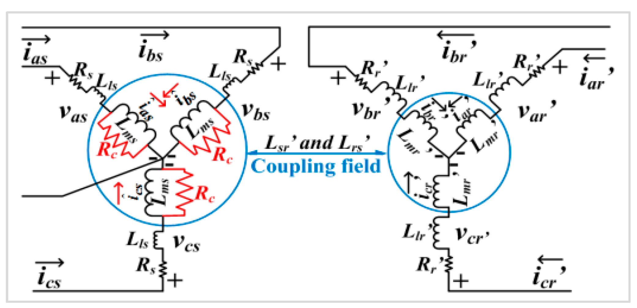
The induction motor simulation in [24] centres on an experimental three-phase stator and rotor circuit design using a magnetic coupling in the intermediate stage, thus neglecting core loss. As seen in Figure 3a, the concept serves as the backbone for major vector control derivations and a design based on the study of an electric drive. The stator-side resistance, leakage inductance, and mutual inductance [25] are denoted as R S , L l S , and L m s . R r , L l r , and L m r are the rotor-side resistance, leakage inductance, and mutual inductance, respectively, as with the stator side. The flux on each rotor or stator circuit is divided into the leakage and mutual components because solely the former reaches the magnetic connection field with which the stator and rotor interface. Figure 3b depicts a conventional steady-state per-phase circuit diagram, which takes core loss into account as the energy lost in   r c _ p h .   L m   is the steady-state magnetising inductance corresponding to (1.5 × L m s ). It should be noted that the connection impacts of other phases are summed into   L m which is acquired from steady-state observations. As a result, the diagram is entirely irrelevant for transient applications [26]. Figure 4 depicts the suggested induction machine design, which is influenced by the preceding two conventional designs. The core loss is understood as a resistor R c in parallel with L m s in each stator phase. It should be noted that R c is not equivalent to r c _ p h , although they were associated in [27].

5.4. Simplified Model

Many stable algorithms contain an adaptable induction machine simulation that is derived from either or both of the equivalent topologies shown. A single-cage induction machine offers modest start-up torque multiplication. With that, the single-cage design is frequently inaccurate. Such issues can be addressed by employing a dual-cage or deeper bar rotor design. A shortage of data frequently limits the usage of dual-cage and deeper bar designs. Improving the torque-slip property of a single-cage design is a streamlined remedy for these instances. The rotor resistance is often changed with slip, which is simple to accomplish during each convergence phase of the model. An adaptable design simulation that relies on the equivalent circuits illustrated in [27] is often utilised for transient reliability research [27,28,29].

5.5. Simplified d–q Design

The steady-state equivalent diagram depicted in [29] serves as the foundation for the concept of the induction machine. The simplified model presented in [29] is utilised for the dynamic simulation diagram. The d–q model of this analysis was regarded as precisely acceptable for acting as a baseline design and was subsequently utilised to assess the adequacy of different designs when implemented for voltage balance analyses [30]. The variables of the designs are depicted in [29].

6. Proposed Design

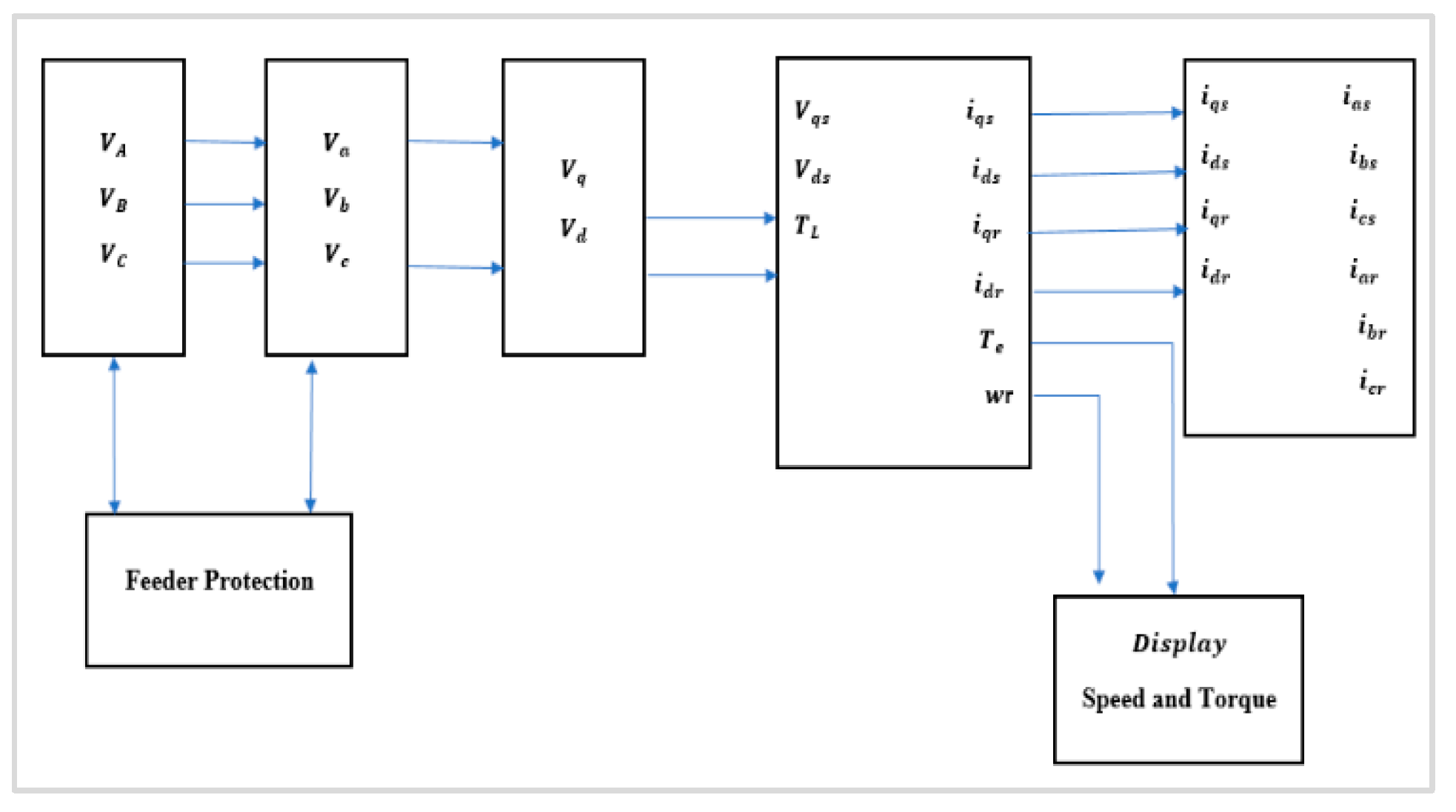
Figure 5 presents the proposed modelling technique for an induction motor; the three-phase supply voltage is supplied to the machine, and then the voltages are transformed using the 0 dq axis to produce the vectors V q   and   V d . Hence, the stator currents and voltages are produced; subsequently, the rotor parameters are also considered. The implementation is outlined in this paper.
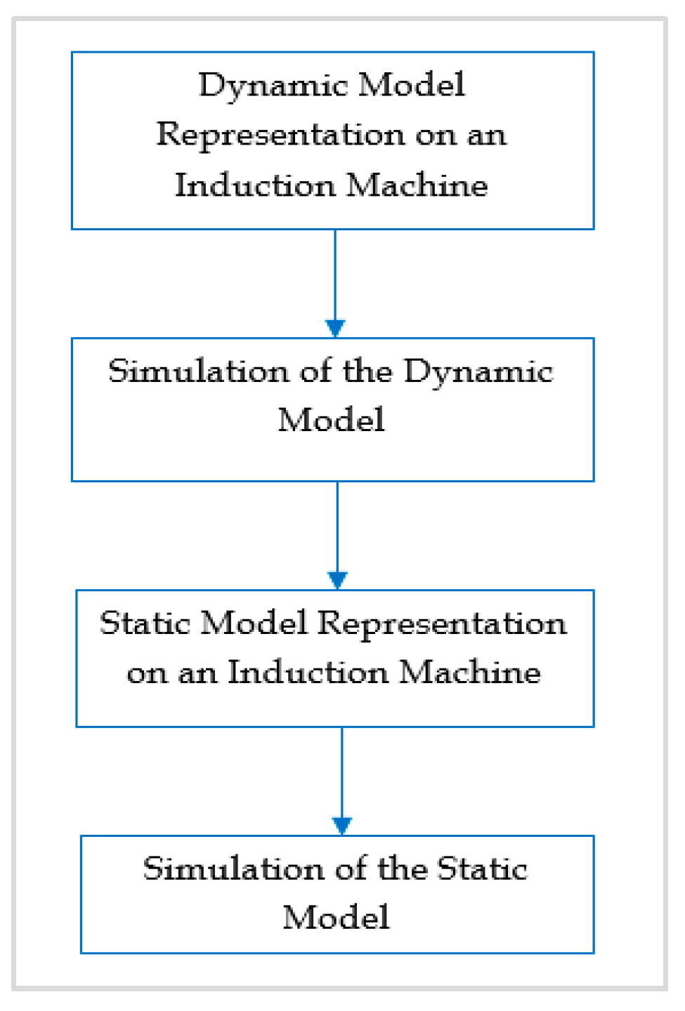
Figure 6 presents the workflow of designing a dynamic and static model of an induction machine. The adaptable design is mathematically represented and subsequently simulated. The equations are implemented separately in terms of subsystems and then integrated to present the full model of the machine. Similarly, for a static model, the derivation is almost the same as that of the dynamic model, but it only changes when the speed is equal to zero (when the machine is stationary). The simulation is also given for the static model [5].

7. Proposed Design

7.1. Dynamic Model

There is a very deep relationship between the stator and the rotor of an induction motor. If one is to extract parameters of the rotor, there is a need to know the relationship of the currents and voltage between these two elements of an induction machine. A d–q axis model of an induction machine is presented in Figure 7a. A q-axis equivalent circuit for an adaptable design of an induction machine is presented in Figure 7b. The stator can then be represented by (1) to (10), and the rotor’s d–q transformation is represented by (11) to (18). The torque is then represented by the stator and rotor parameters (19) [31].
Stator voltage modelling:
V s d = 2 3 [ cos ( θ d s × v d s ) + ( cos ( θ d s × 2 π 3 × v b ) ) + ( cos ( θ d s × 4 π 3 × v a ) ) ]
V s q = 2 3 [ sin ( θ d s × v d s ) + ( sin θ d s × 2 π 3 × v b ) + ( sin θ d s × 4 π 3 × v a ) ]
V s d and V s q may now be simplified to:
V s d = R S × i s d + d d t ( λ s d ) ω d × λ s q
V s q = R s × i s q + d d t ( λ s d ) ω d × λ s d
Stator fluxes:
λ s d = L S × i s d + L m × i r d
λ s q = L S × i s q + L m × i r d
Stator currents:
i d s = 1 X l S ( λ d s λ m d )
i q s = 1 X l S ( λ q s λ m q )
Stator voltages:
V s d = R S × i s d + d d t ( λ s d ) ω d × λ s q
V s q = R S × i s q + d d t ( λ s q ) ω d × λ s d
Mathematical model of the rotor:
V r d = R r × i r d + d d t ( λ r d ) ω d A × λ r q
V r q = R r × i r d + d d t ( λ r d ) ω d A × λ r d
Rotor flux equations:
λ r d = L r × i r d + L m × i s d
λ r q = L r × i r q + L m × i s d
Rotor currents:
i d r = 1 X l S ( λ d r λ m d )
i q r = 1 X l S ( λ q r λ m q )
Rotor voltages:
V r d = R r × i r d + d d t ( λ r d ) ω d A × λ r q
V r q = R r × i r q + d d t ( λ r q ) ω d A × λ r d
Electromagnetic torque:
T e m = P 2 × L m ( i s q × i r d i s d × i r q )
where
V q s , V d s   are   the   q   and   d axes of the stator voltage(s).
V q r , V d r are   the   q   and   d axes of the rotor voltage(s).
λ m q , λ m d are   the   q   and   d axes magnetising the flux linkages.
R S is the stator resistance.
R r is the rotor resistance.
X l s is the stator leakage reactance.
X l r is the rotor leakage reactance.
p is the number of poles.
T e m is the magnetic torque.
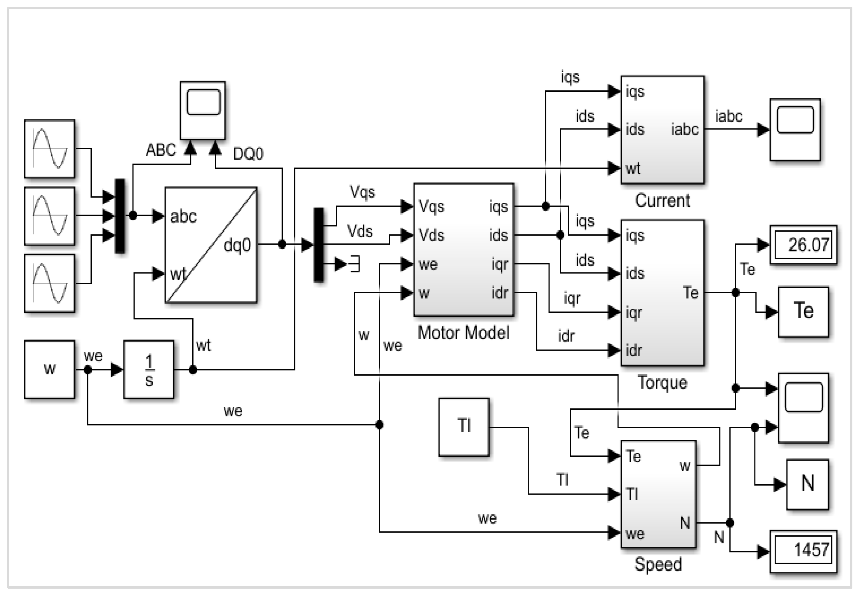
Figure 8a,b present the implantation of the dynamic model of the induction motor. The stator supply voltages and currents are presented in Figure 8a,b. The rotor currents are presented in Figure 8b. The torque and speed are presented in Figure 9a,b [32], where Figure 10 illustrates the complete model of the dynamic induction motor.

7.2. Static Model

The standard-frame velocity in a static-source framework is that of the stator, i.e., ω s = ω r = 0 . Such a standard frame is chosen when potential asymmetrical differences in the stator are interrupted and the potential differences in the rotor are symmetrical. The potential difference equations of an induction machine in a static reference frame are determined by substituting ω r = 0 into (3). The resultant solution is the static design of an induction machine in which the rotor is removed. As a result, the machinery can be described as static.
It is noticeable that there is a major relationship between the stator and the rotor of an induction motor. As the subscripts, r and s indicate the stator (s) and rotor (r). The electromagnetic subscripts are i, v, and λ. The resistance is r, the leakage inductance is L l , and the mutual inductance is L m . The phase voltages are represented by a, b, and c.
The actual values of the induction motor’s parameters can be derived from the model specified in Section 4 [26]. To determine the parameters, a no-load test and a load test must be performed, so the parameters can be determined as follows.
The no-load test is performed by supplying the voltage V S at a rated frequency. The motor will rotate close to a synchronous speed, resulting in a close-to-zero slip [22].
Assuming that R S   ,   Ω ,   and   L S H are much lower than the magnetising inductance L m H , the following equation is derived [1].
L m = V S 2 π f s I
where V S is the applied phase voltage in the stator, I is the current supplied to the stator, and f s is the stator frequency.
Now that the magnetising inductance has been determined, the other parameters are extracted with the locked rotor test, and the resulting equivalent circuit is shown in Figure 11.
[ v d s v q s v d r v q r ] = [ R S + s L s 0 L m ω r L m 0 R s + s L s R s + s L s s L m s L m 0 R r + s L r ω r L r 0 s L m ω r L r R s + s L r ] [ i d s i q s i d r i q r ]
Should ω r = ω s = 0 , Equation (21) becomes:
[ v d s v q s v d r v q r ] = [ R S + s L s 0 L m 0 0 R s + s L s R s + s L s s L m s L m 0 R r + s L r 0 0 s L m 0 R s + s L r ] [ i d s i q s i d r i q r ]
where R S and R r are the resistances of the stator and rotor, L S and L r are the stator’s and rotor’s self-inductance and the stator’s and rotor’s speeds.
Figure 12 illustrates a static model of an induction motor.

8. Results

The following parameters were acquired from experimental work with a three-phase induction motor. These settings were then utilised to simulate and examine the behaviour of the induction motor using Matlab/Simulink.

8.1. The Machine’s Steady-State Performance Behaviour When Loaded from 0 to 125% of the Rated Load, Shown in Both Tabular and Graphical Form with Current, Power Factor, Real Power, Reactive Power, Speed, Efficiency, and Power Factor versus the Percentage or Per-Unit Loading

The parameters indicated in Table 1 were used to simulate the induction machine using Matlab/Simulink were:
The rated torque was not provided; therefore, before we can calculate the rated torque, the synchronous speed of the machine must first be calculated. The synchronous speed is calculated as follows:
N s = 120 × f p = 1800   r p
Knowing the synchronous speed of a four-pole, 60 Hz machine, the rated torque may now be calculated.
T = P r a t e d × 9.5493 N s = 39.78875   N . m
To simplify, 40 N.m was used as the rated torque value. Table 2 provides the results obtained from the induction machine.
As seen in Figure 13a, the higher the torque load is, the higher the current will be. In Figure 13b, we can see that the active power drawn by the induction machine is almost linear. Thus, the active power is proportional to the percentage of the loading.
As shown in Figure 14a, the efficiency of the induction motor is poor when the machine is lightly loaded. Theoretically, the optimal point must be at 100% loading; however, in this case, the optimal point is at 80–90%. This is mainly due to additional power losses (theoretical vs practical).
Figure 14b illustrates that the reactive power initially decreases. This is because the power factor is poor with no load and increases with the increase in the load; however, the reactive power drawn will also increase due to the increase in the load.
As shown in Figure 15a, the power factor is similar to the efficiency. The lower the load is, the lower the power factor will be, and a very good power factor is reached at the rated torque.
As shown in Figure 15b, the induction machine’s speed decreases as the torque load increases, starting from a value that is very close to the synchronous speed. Because the machine acts as an induction motor, it will always run below the synchronous speed.

8.2. Transient Behaviour of the Current and Torque Versus Speed during Starting, Assuming That (i) the Machine Is Unloaded, (ii) the Machine Is 50% Loaded, and (iii) the Machine Is 100% Loaded
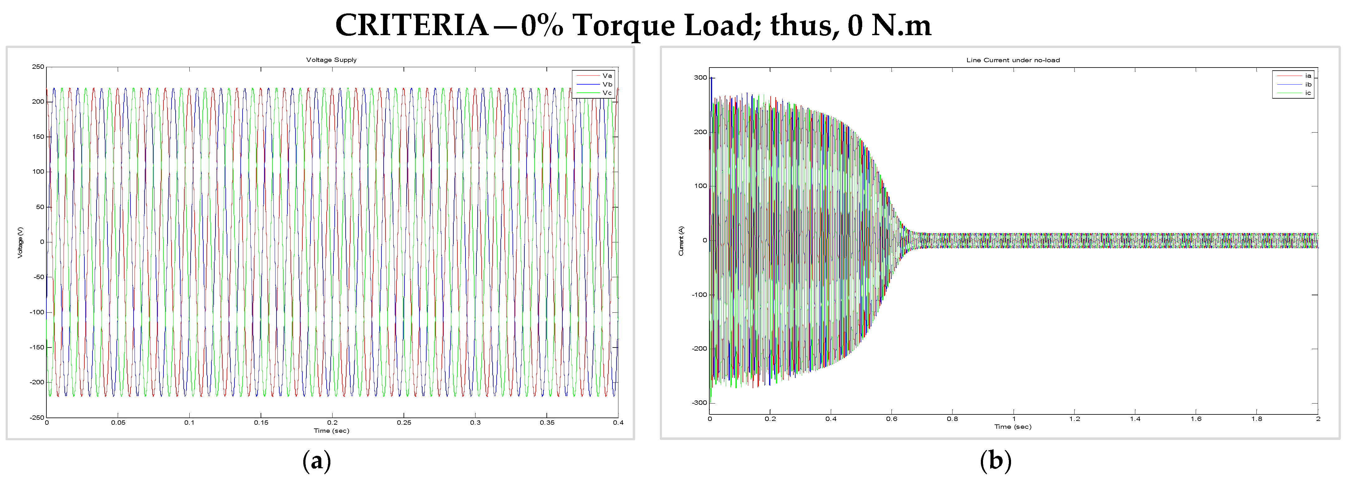
In Figure 16b, we see the three-phase current. One characteristic of an induction machine is that it has a very high starting current in the transient state.
As seen in Figure 17a, the electromagnetic torque oscillates during the transient state until the oscillation stops and moves towards the torque load.
In Figure 17b, we see the same oscillation behaviour in the transient state; however, the machine reaches an optimal point that is close to the synchronous speed due to lack of a load.
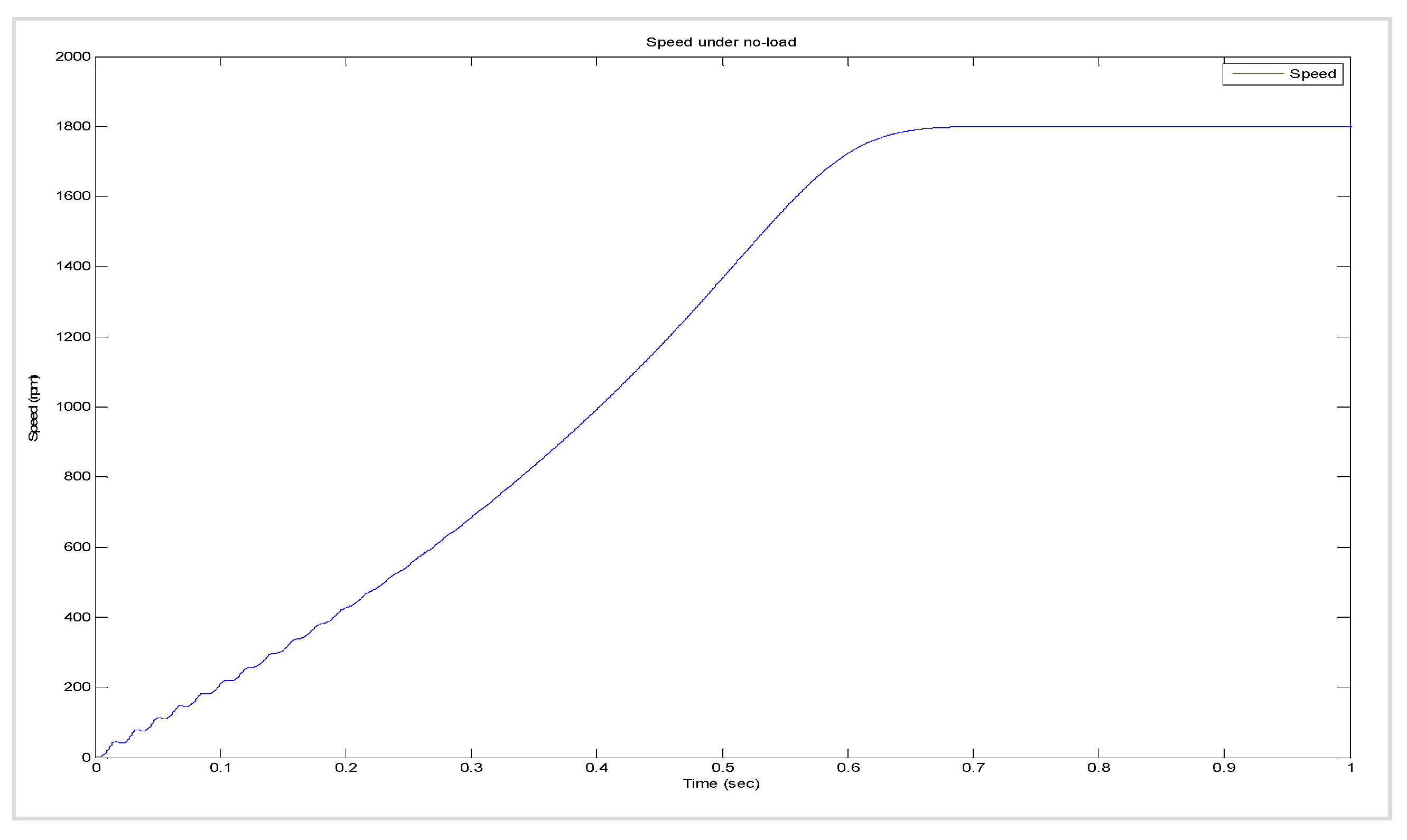
In Figure 18, we see a small disturbance in the speed. This is due to the oscillation of the electromagnetic torque. The motor reaches a steady-state close to the synchronous speed due to the lack of a load.
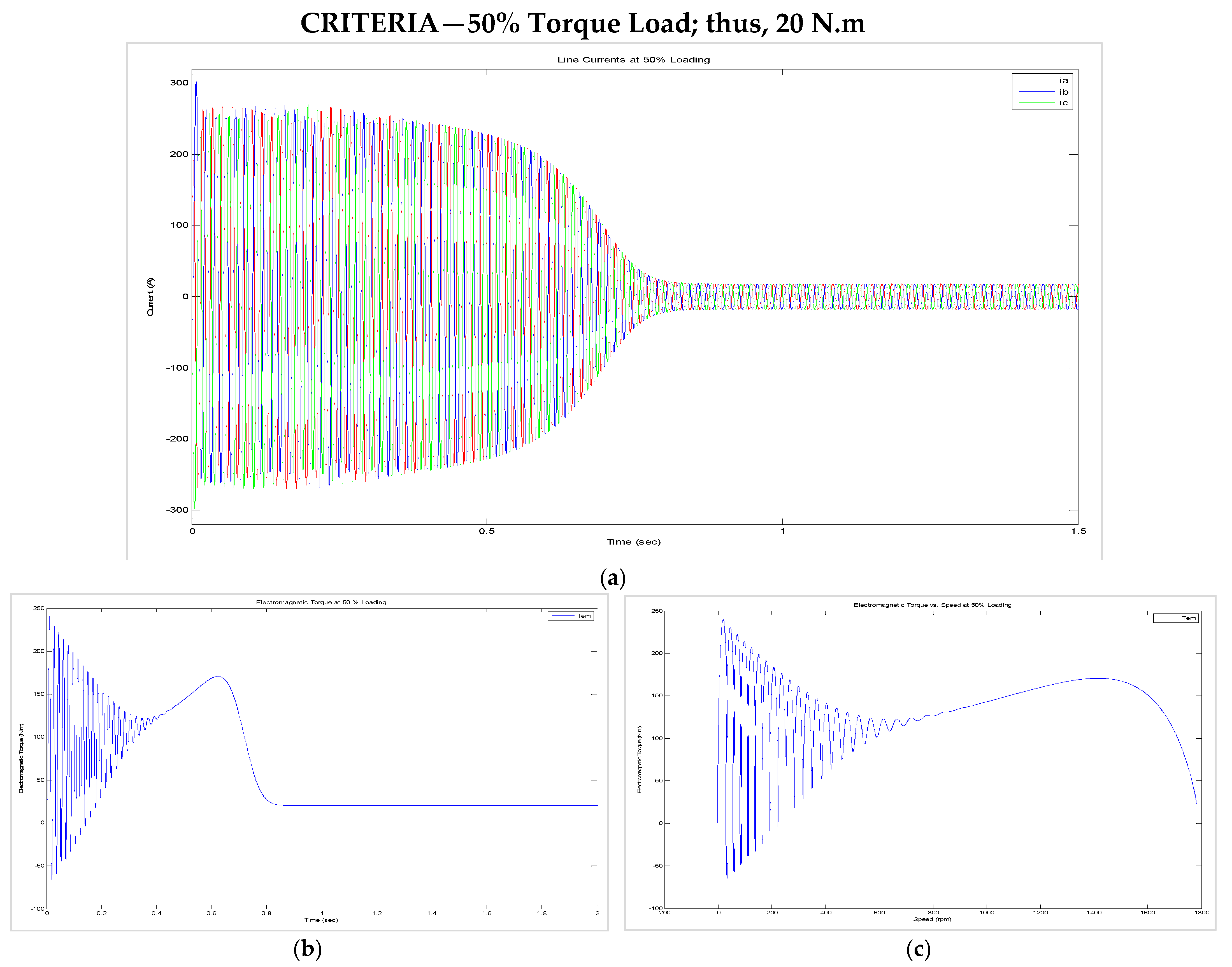
The supply stays the same because no impedances exist at the source in this simulation. Figure 19a–c illustrates that the steady-state reached approximately 0.15 s later than with no load. This was expected because of the increase in the load.
As seen in Figure 19a, the amplitude was not affected by the higher magnitude of the load. Therefore, the conclusion can be drawn that the machine current is only a function of the machine’s parameters.
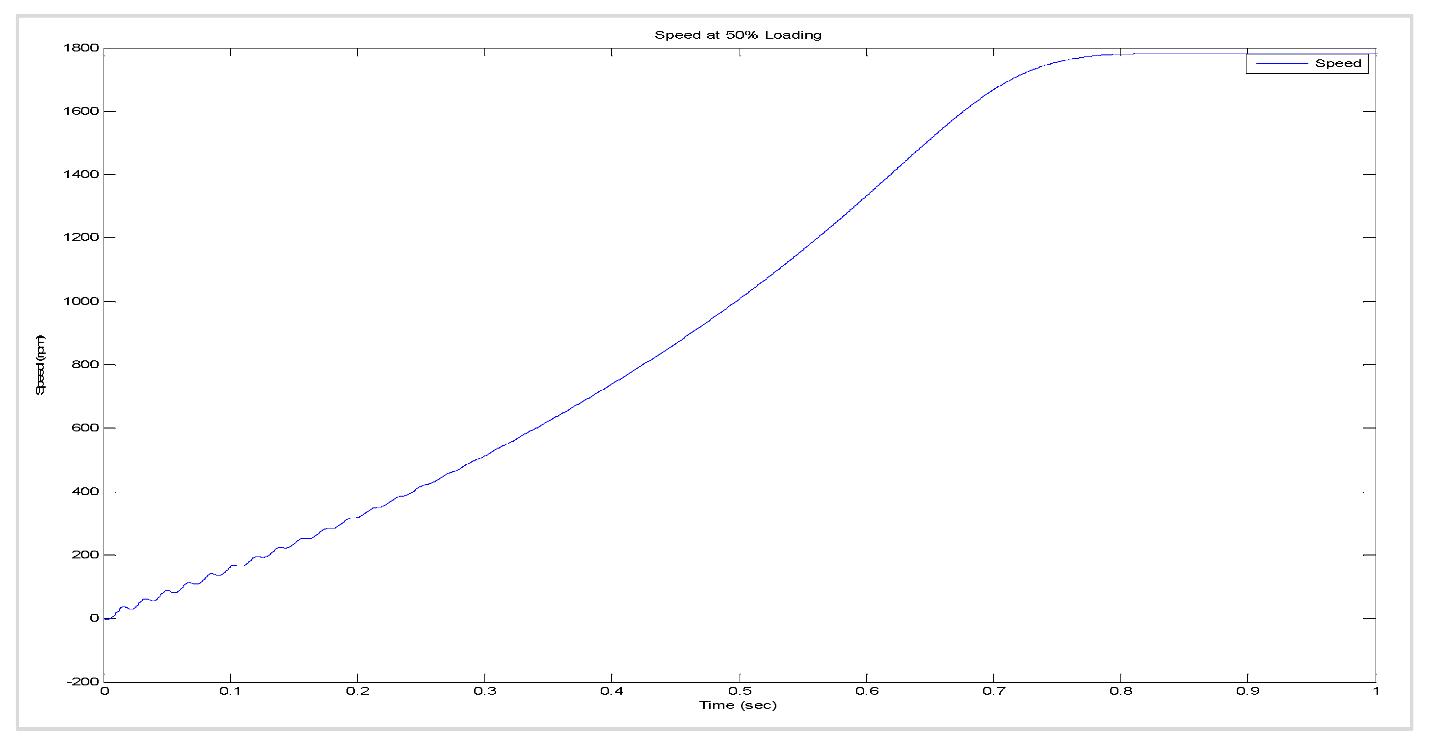
As seen in Figure 20, the optimal point is at a lower speed than with no load.
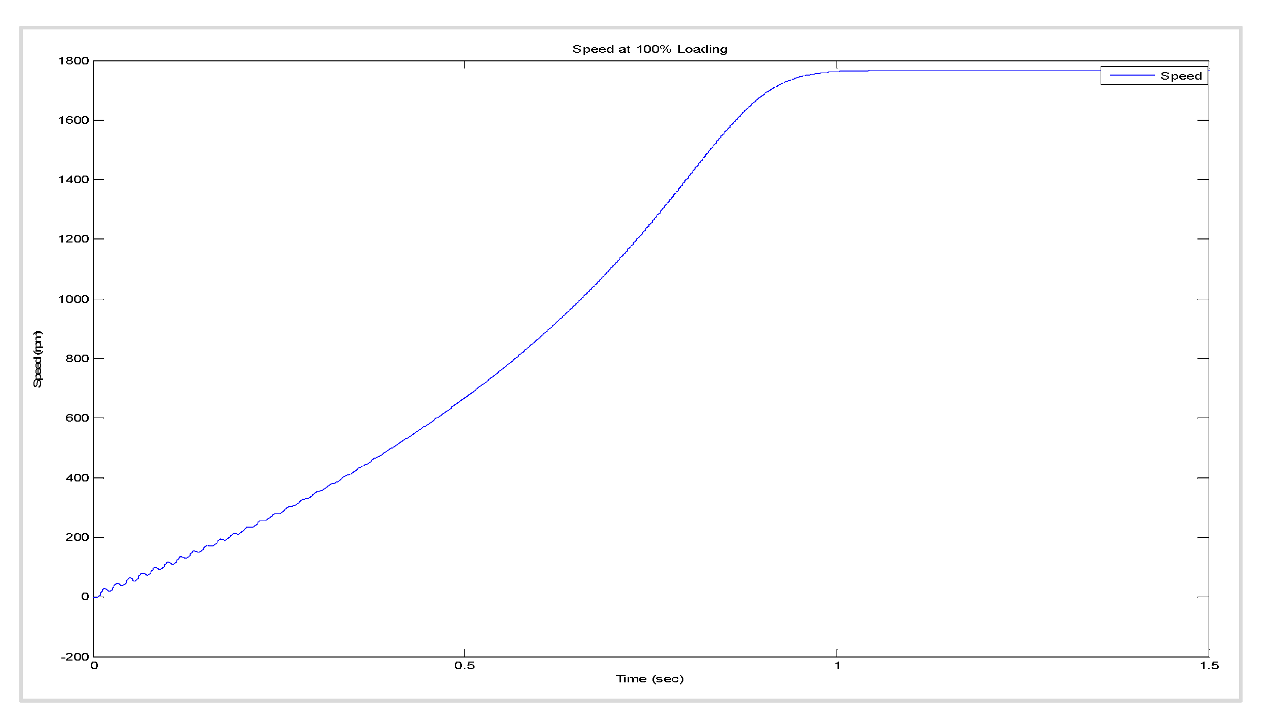
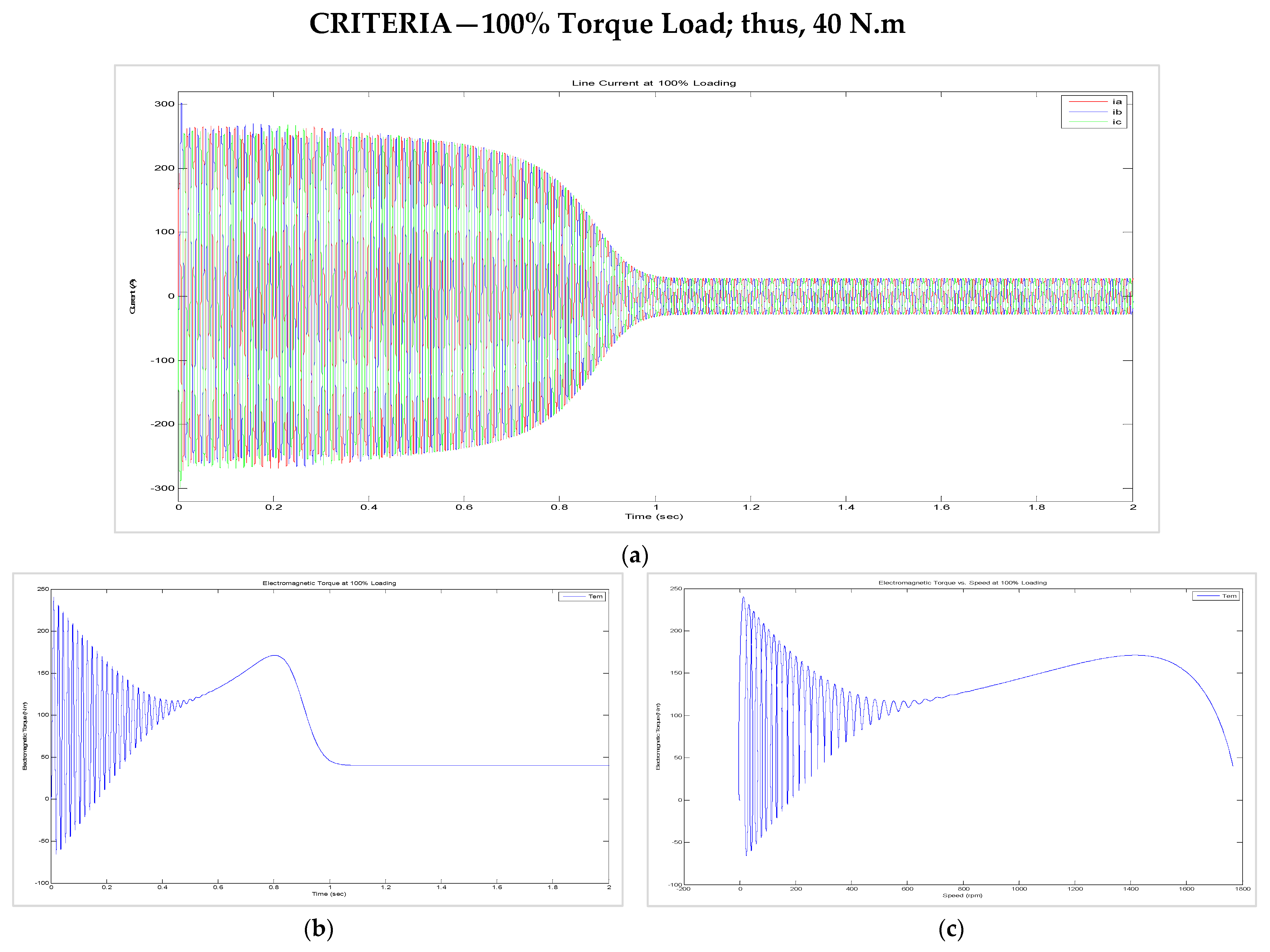
As seen previously, as the loading increases, it takes longer for the steady-state to be achieved. At a full load (100% torque load), reaching the steady-state took approximately 0.2 s longer than with the half load (50% torque load). This can be seen in Figure 21a–c.
Figure 21. (a) Current at 100% loading. (b) Electromagnetic torque at 100% loading. (c) Electromagnetic torque vs speed at 100% loading. As seen in Figure 22b, the optimal point is at a lower speed than with no-load or half-load.
Energies 15 03564 g021

8.3. Dynamic Behaviour of the Machine When (i) the Load Was Suddenly Changed from 50% to 100% and (ii) the Supply Voltage (for the Motors) or the Torque Input (for the Generators) Was Suddenly Halved While the Load Was Maintained at 100%

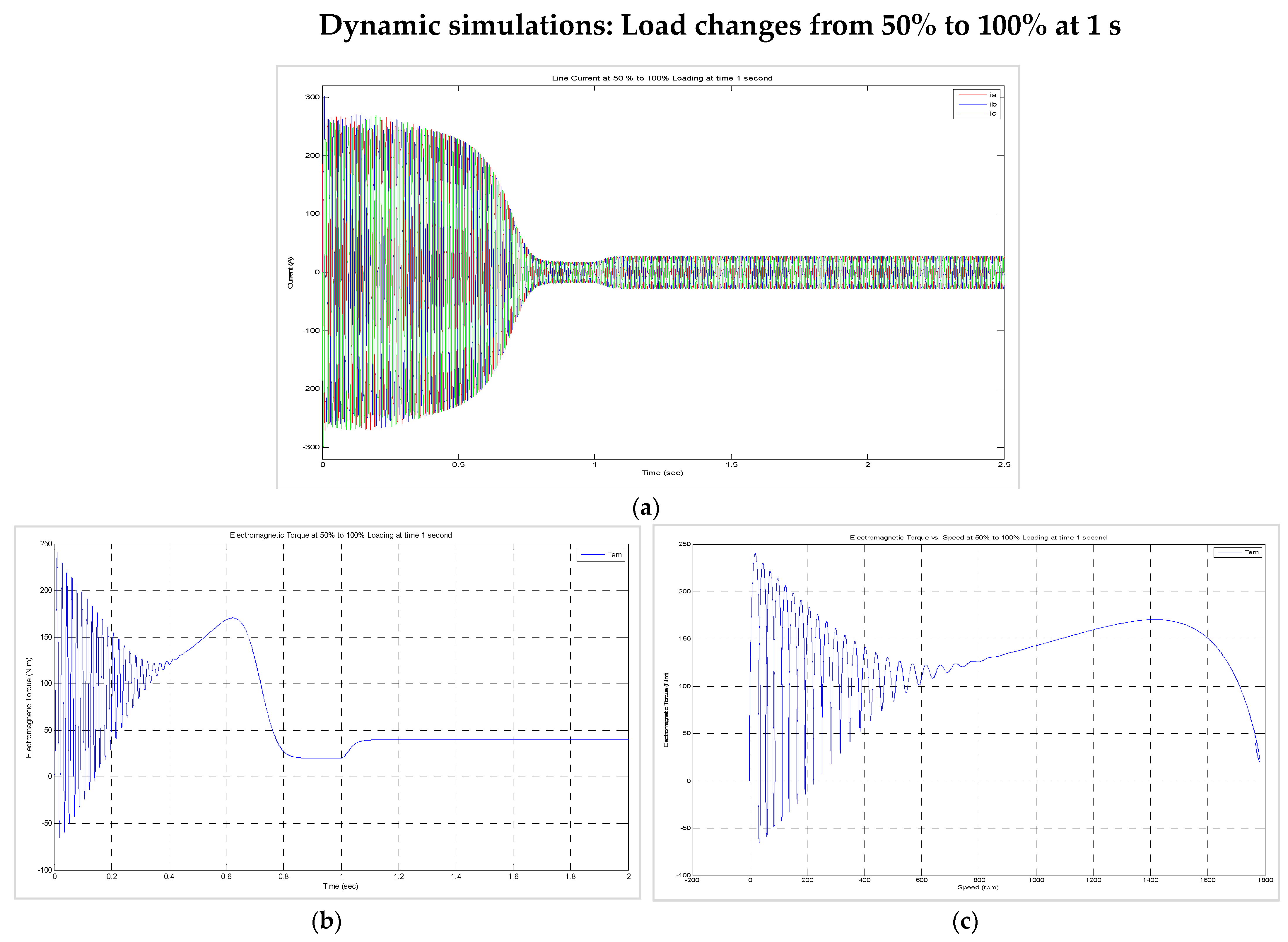
As seen in Figure 23a, we have a normal transient state; however, an increase in currents may be seen as the load changes from a half load to a full load (50% to 100%).
As seen in Figure 23b, we have a normal transient state; however, with an increase in the electromagnetic torque, the load changes from a half load to a full load (50% to 100%). It can be seen in Figure 23c that the optimal point of the full load (100%) is at a lower speed; however, there is a higher torque than with the half load.
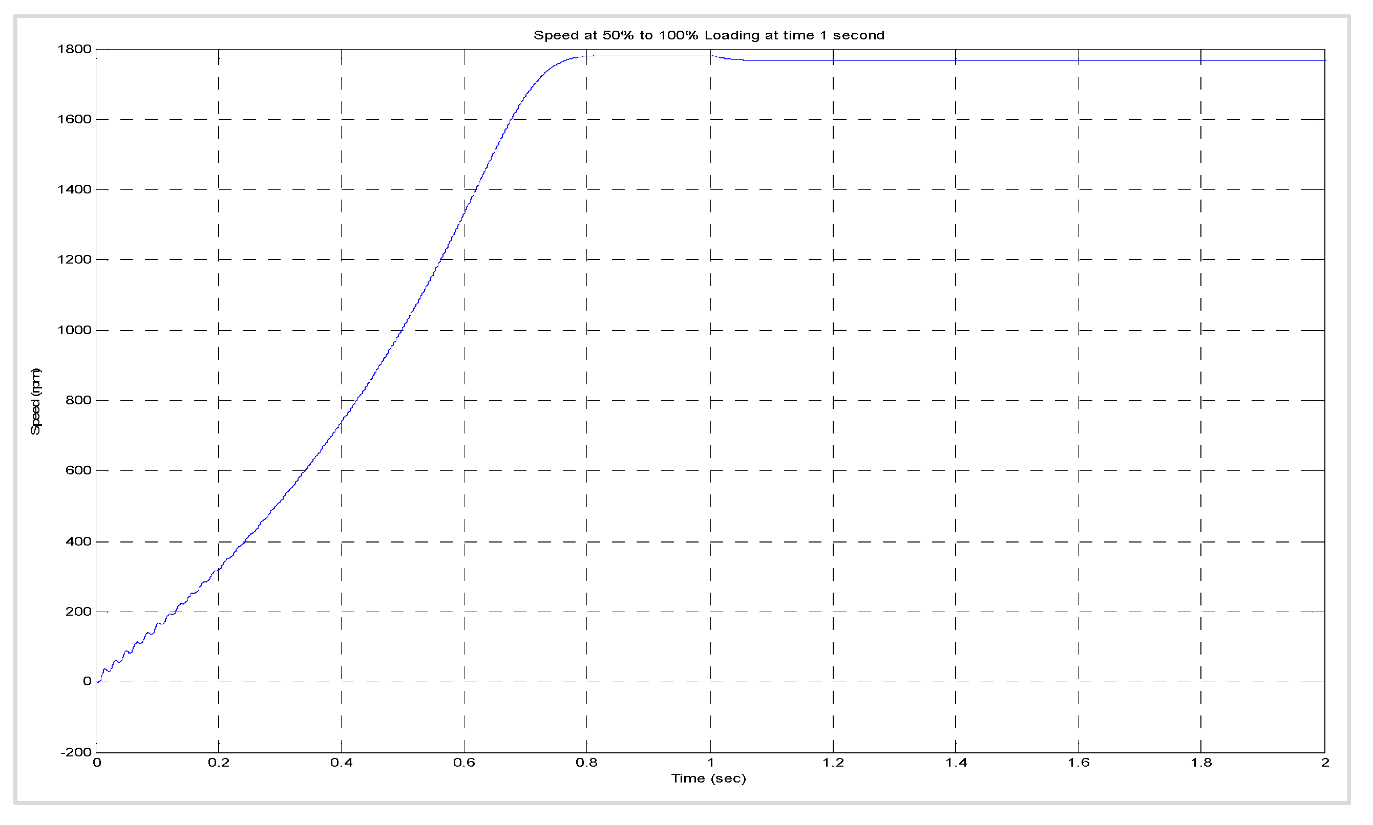
In Figure 24, we see the decrease in the speed of the machine after 1 s when the load changes from 50% to 100%.
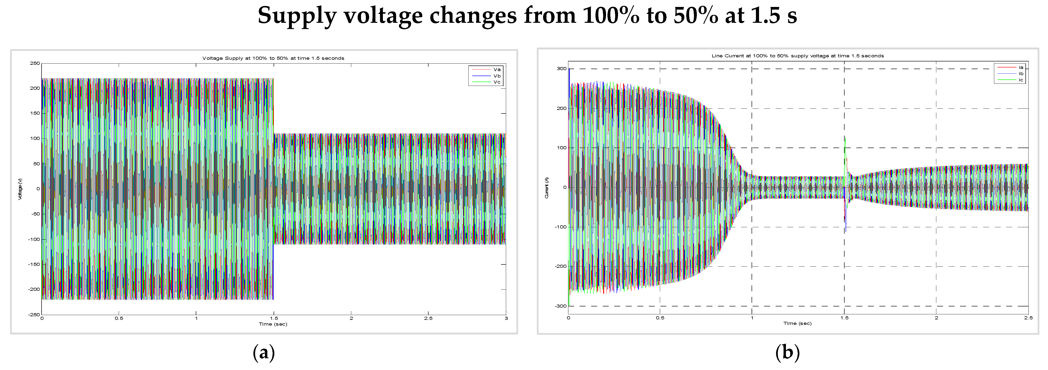
As seen in Figure 25a, the voltage supply is halved at 1.5 s. We can see in Figure 25b that the current at 1.5 s approximately doubles. At 1.5 s, the protection of the induction machine will operate with a disconnect from the supply voltage.
In Figure 26a, at 1.5 s, the machine cannot produce the electromagnetic torque required for the load torque; thus, the speed of the machine decreases. In Figure 26b, we see that no stable point has been reached.
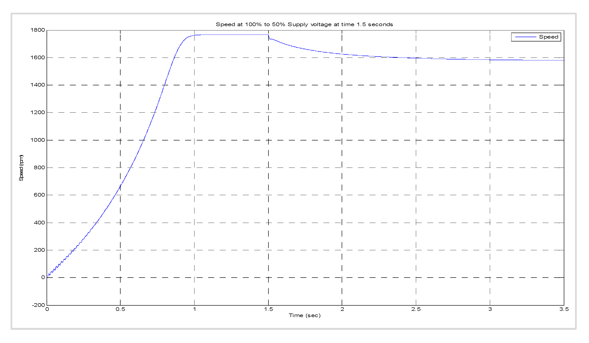
As seen in Figure 27, the speed decreases due to the supply voltage being halved at 1.5 s; thus, the electromagnetic torque is less than the loading torque. This means that the machine is not able to operate under these specific conditions.

9. Conclusions

The performance of the stator and rotor variables was effectively studied by utilising dynamic and static Simulink designs for the modelling of an induction machine. In contrast to several existing induction machine design applications, the operator has access to all internal parameters in this design in order to gain knowledge about the machine’s operations. By utilising such designs, any machine control method can be modelled in the Matlab/Simulink software without estimation techniques. For every module, individual variable calculations were performed. Each designer’s function was modelled, and critical variables were observed.
In this work, a dq0-direct axis algorithm was presented in order to implement both static and dynamic modelling of a three-phase induction machine due to possible faults and high-performance requirements for induction machines. The proposed algorithm was compared with several conventional methods. It was observed that under stable conditions of the machinery, the proposed algorithm could remove any developing faults. This conserves time and minimises the labour required of an operator, which makes the proposed algorithm more efficient. Furthermore, the machine demonstrated a steady-state performance with respect to the current, active power, efficiency, reactive power, power factor, and speed when the torque loads ranged from 0% to 125% of the nominal torque. The transient behaviour of the machine was shown through the current, electromagnetic torque, electromagnetic torque versus speed, and speed under no-load, half-load (50%), and full-load (100%) conditions. Finally, the results of the proposed technique were compared to the results of the measured parameters. It was found that when the load changed from a half load (50%) to a full load (100%), the supply voltage was suddenly halved with the load at full load (100%). It was observed that the proposed algorithm provides accurate estimates with a deviation of not more than +/−2% from the measured parameters.

Author Contributions

Conceptualisation and methodology, P.F.L.R. and M.K.N.; Software, P.F.L.R.; Validation, P.F.L.R.; Investigation, P.F.L.R.; Writing—original draft preparation, P.F.L.R. and M.K.N.; Writing—review and editing, P.F.L.R.; Supervision, P.F.L.R. All authors have read and agreed to the published version of the manuscript.

Funding

This research received no external funding.

Acknowledgments

The authors would like to acknowledge the reviewers for their academic and specialist assistance and beneficial remarks.

Conflicts of Interest

The authors declare no conflict of interest.

References

  1. Rajput, S.; Bender, E.; Averbukh, M. Simplified algorithm for assessment equivalent circuit parameters of induction motors. IET Electr. Power Appl. 2020, 14, 426–432. [Google Scholar] [CrossRef]
  2. Ahmed, M.; Vahidnia, A.; Datta, M.; Meegahapola, L. An adaptive power oscillation damping controller for a hybrid AC/DC microgrid. IEEE Access 2020, 8, 69482–69495. [Google Scholar] [CrossRef]
  3. Iegorov, O.; Iegorova, O.; Miroshnyk, O.; Savchenko, O. Improving the accuracy of determining the parameters of induction motors in transient starting modes. Energetika 2020, 66, 15–23. [Google Scholar] [CrossRef]
  4. Wang, H.; Chau, K.; Lee, C.H.; Cao, L.; Lam, W.H. Design, Analysis, and Implementation of Wireless Shaded-Pole Induction Motors. IEEE Trans. Ind. Electron. 2020, 68, 6493–6503. [Google Scholar] [CrossRef]
  5. Rahaman, N.; Govindraju, H. Modeling and Simulation of a Three-Phase Electric Traction Induction Motor Using MATLAB/Simulink. Int. J. Electr. Electron. Comput. Syst. 2014, 2, 5. [Google Scholar]
  6. Kozjaruk, A.E.; Vasilev, B.U.; Shtop, S.A.; Serdukov, N.A. Currents in bearings of induction motors of electric drives with semiconductor converter. In Proceedings of the 17th International Ural Conference on AC Electric Drives (ACED), Ekaterinburg, Russia, 26–30 March 2018; pp. 1–5. [Google Scholar]
  7. Maleki, M.G.; Chabanloo, R.M.; Farrokhifar, M. Accurate coordination method based on the dynamic model of overcurrent relay for industrial power networks taking contribution of induction motors into account. IET Gener. Transm. Distrib. 2019, 14, 645–655. [Google Scholar] [CrossRef]
  8. Abdelwanis, M.I.; Selim, F.; El-Sehiemy, R. An efficient sensorless slip dependent thermal motor protection schemes applied to submersible pumps. Int. J. Eng. Res. Afr. 2015, 14, 75–86. [Google Scholar] [CrossRef]
  9. Chitra, V.; Prabhakar, R. Induction motor speed control using fuzzy logic controller. World Acad. Sci. Eng. Technol. 2006, 23, 17–22. [Google Scholar]
  10. Elnaghi, B.E.; Mohammed, R.H.; Dessouky, S.S.; Shehata, M.K. Load test of induction motors based on PWM technique using genetic algorithm. Int. J. Eng. Manuf. 2019, 9, 1. [Google Scholar] [CrossRef]
  11. Sadasivan, J.; Mammen, O. Genetic algorithm based parameter identification of three phase induction motors. Int. J. Comput. Appl. 2011, 31, 51–56. [Google Scholar]
  12. Jirdehi, M.A.; Rezaei, A. Parameters estimation of squirrel-cage induction motors using ANN and ANFIS. Alex. Eng. J. 2016, 55, 357–368. [Google Scholar] [CrossRef] [Green Version]
  13. Keerthipala, W.; Duggal, B.; Chun, M.H. Torque and speed control of induction motors using ANN observers. Int. Conf. Power Electron. Drives Energy Syst. Ind. Growth Proc. 1998, 1, 282–288. [Google Scholar]
  14. Chen, J.; Severson, E.L. Design and modeling of the bearingless induction motor. In Proceedings of the IEEE International Electric Machines & Drives Conference (IEMDC), San Diego, CA, USA, 12–15 May 2019; pp. 343–350. [Google Scholar]
  15. Swami, H.; Jain, A.K. An Improved Scalar Controlled Drive Based on Steady State Model of Vector Controlled Drive for Squirrel Cage Induction Motor. In Proceedings of the IEEE 30th International Symposium on Industrial Electronics (ISIE), Kyoto, Japan, 20–23 June 2021; pp. 1–6. [Google Scholar]
  16. Levi, E.; Vukosavic, S.; Jones, M. Vector control schemes for series-connected six-phase two-motor drive systems. IEEE Proc.-Electr. Power Appl. 2005, 15, 226–238. [Google Scholar] [CrossRef] [Green Version]
  17. Goolak, S.; Gubarevych, O.; Yermolenko, E.; Slobodyanyuk, M.; Gorobchenko, O. Mathematical modeling of an induction motor for vehicles. East.-Eur. J. Enterp. Technol. 2020, 2, 104. [Google Scholar] [CrossRef]
  18. Prabakaran, S.; Venkatesan, S. Analysis of 3 phase Induction Motor Protection Using Numerical Relay. Int. J. Eng. Tech. 2018, 4, 513–519. [Google Scholar]
  19. Yildiz, R.; Barut, M.; Demir, R. Extended Kalman filter based estimations for improving speed-sensored control performance of induction motors. IET Electr. Power Appl. 2020, 14, 2471–2479. [Google Scholar] [CrossRef]
  20. Zhefeng, M.L.; Zhang, G.; Diao, L.; Liu, Z. Extended Kalman Filter based on inverse Γ model of induction motor. In Proceedings of the IEEE Vehicle Power and Propulsion Conference, Harbin, China, 3–5 September 2008; pp. 1–5. [Google Scholar]
  21. Khamehchi, S.; Mölsä, E.; Hinkkanen, M. Comparison of standstill parameter identification methods for induction motors. In Proceedings of the IEEE 9th International Symposium on Sensorless Control for Electrical Drives (SLED), Helsinki, Finland, 13–14 September 2018; pp. 156–161. [Google Scholar]
  22. Bimal, K. Modern Power Electronics and AC Drives; Prentice-Hall: Hoboken, NJ, USA, 2001. [Google Scholar]
  23. Tang, Y.; He, X.; Cao, J. Fast calculation method of transient temperature rise of motor for electro-mechanical braking. Sci. Prog. 2021, 104, 368504211024553. [Google Scholar] [CrossRef] [PubMed]
  24. Krause, P.C.; Wasynczuk, O.; Sudhoff, S.D.; Pekarek, S.D. Analysis of Electric Machinery and Drive Systems; John Wiley & Sons: Hoboken, NJ, USA, 2013. [Google Scholar]
  25. Wang, L.; Aleksandrov, S.; Tang, Y.; Paulides, J.J.; Lomonova, E.A. Fault-tolerant electric drive and space-phasor modulation of flux-switching permanent magnet machine for aerospace application. IET Electr. Power Appl. 2017, 11, 1416–1423. [Google Scholar] [CrossRef]
  26. Duan, N.; Ma, X.; Lu, S.; Wang, S.; Wang, S. Simulation Calculation of Loss of Induction Traction Motor. In The Proceedings of the 9th Frontier Academic Forum of Electrical Engineering; Springer: Berlin/Heidelberg, Germany, 2021; pp. 599–606. [Google Scholar]
  27. Liu, Y.; Bazzi, A.M. A detailed induction machine core loss model in the arbitrary reference frame. In Proceedings of the IEEE Applied Power Electronics Conference and Exposition (APEC), Charlotte, NC, USA, 15–19 March 2015; pp. 2617–2622. [Google Scholar]
  28. Shepard, R.A. A Computational Investigation of Cathode Materials for Next-Generation Secondary Batteries. Ph.D. Thesis, State University of New York at Binghamton, Binghamton, NY, USA, 2021. [Google Scholar]
  29. Claassens, A.J. Transient Modelling of Induction Motors in a Petrochemical Plant Using Matlab. Master’s Thesis, Stellenbosch University, Stellenbosch, South Africa, 2008. [Google Scholar]
  30. Smith, J.R.; Chen, M.J. Three-Phase Electrical Machine Systems: Computer Simulation; Research Studies Press Taunton: Taunton, UK, 1993. [Google Scholar]
  31. Pereira, L.; Kosterev, D.; Mackin, P.; Davies, D.; Undrill, J.; Zhu, W. An interim dynamic induction motor model for stability tudies in the WSCC. IEEE Trans. Power Syst. 2002, 17, 1108–1115. [Google Scholar] [CrossRef]
  32. Diaz, A.; Saltares, R.; Rodriguez, C.; Nunez, R.F.; Ortiz-Rivera, E.I.; Gonzalez-Llorente, J. Induction motor equivalent circuit for dynamic simulation. In Proceedings of the IEEE International Electric Machines and Drives Conference, Miami, FL, USA, 3–6 May 2009; pp. 858–863. [Google Scholar]
Figure 2. (a) Transient circuit of the inverse Γ model; (b) steady-state inverse Γ model [20].
Energies 15 03564 g002
Figure 3. (a) The classical induction machine model considers only copper loss; (b) the steady-state per-phase equivalent circuit [27].
Energies 15 03564 g003
Figure 4. Loss model of an induction motor [27].
Energies 15 03564 g004
Figure 5. A proposed dynamic model of an induction motor.
Energies 15 03564 g005
Figure 6. Design workflow.
Energies 15 03564 g006
Figure 7. (a) The d-axis equivalent circuit of an induction motor. (b) The q-axis equivalent circuit of an induction motor.
Energies 15 03564 g007
Figure 8. (a) Simulation of a dynamic model of an induction motor; (b) current equation of the stator.
Energies 15 03564 g008
Figure 9. (a) Torque equation; (b) speed equation.
Energies 15 03564 g009
Figure 10. A complete model of the dynamic induction motor.
Energies 15 03564 g010
Figure 11. Equivalent circuit of the locked rotor.
Energies 15 03564 g011
Figure 12. A static model of an induction motor.
Energies 15 03564 g012
Figure 13. (a) Current vs torque load; (b) active power vs torque load.
Energies 15 03564 g013
Figure 14. (a) Efficiency vs torque load; (b) reactive power vs torque load.
Energies 15 03564 g014
Figure 15. Power factor vs torque load (a); speed vs torque load (b).
Energies 15 03564 g015
Figure 16. (a) Voltage supply under no-load; (b) line currents under no-load.
Energies 15 03564 g016
Figure 17. (a) Electromagnetic torque under no-load; (b) electromagnetic torque vs speed under no-load.
Energies 15 03564 g017
Figure 18. Speed under no load.
Energies 15 03564 g018
Figure 19. (a) Line currents at 50% loading. (b) Electromagnetic torque at 50% loading. (c) Electromagnetic torque vs. speed at 50% loading.
Energies 15 03564 g019
Figure 20. The speed at 50% loading.
Energies 15 03564 g020
Figure 22. The speed at 100% loading.
Energies 15 03564 g022
Figure 23. (a) Line current at 50% to 100% loading at 1 s. (b) Electromagnetic torque at 50% to 100% loading at 1 s. (c) Electromagnetic torque vs. speed at 50% to 100% loading at 1 s.
Energies 15 03564 g023
Figure 24. Speed at 50% to 100% loading at 1 s.
Energies 15 03564 g024
Figure 25. (a) The change in the voltage supply from 100% to 50% at 1.5 s. (b) Line current when the voltage changes from 100% to 50% at 1.5 s.
Energies 15 03564 g025
Figure 26. (a) Electromagnetic torque when the supply voltage changes from 100% to 50% at 1.5 s. (b) Electromagnetic torque vs speed when the supply voltage changes from 100% to 50% at 1.5 s.
Energies 15 03564 g026
Figure 27. The speed when the supply voltage changes from 100% to 50% at 1.5 s.
Energies 15 03564 g027
Table 1. Parameters used for induction motor simulation.
P r a t e d 7.5   kW L s 42.5 e 3 H
f 60   Hz L r 41.8 e 3 H
V m 220   V L m 41.2 e 3 H
r s 288 e 3 Ω L l s L s L m
r r 158 e 3 Ω L l r L r L m
J 0.4   kg ·   m 2 P 4
Table 2. The induction machine’s results.
Torque Load (%)Current (A)PinPoutEfficiency (%)QinPower Factor (PF)Speed (rpm)Tem (N.m)
(W)(W)(Var)
09.70881.421.14 × 10−71.40 × 10−945300.0179718006.05 × 10−10
109.826837.4752.70.898845090.182617974
2010.23159815030.940144990.334817948
3010.9236522500.941145020.465179012
4011.78313629940.945245170.5703178716
5012.85391337360.949745440.6525178420
6014.06469544750.952145840.7155178024
7015.39548252100.953246380.7635177728
8016.81627659430.954947050.8001177332
9018.3707566720.954947860.8283177036
10019.86788173990.953148810.8502176640
11021.48869281220.950449900.8672176344
12023.14951088410.946951150.8807175948
12523.99992291990.945451840.8863175750
Publisher’s Note: MDPI stays neutral with regard to jurisdictional claims in published maps and institutional affiliations.