Abstract
Carbon dioxide’s (CO2) ability to reach the supercritical phase (7.39 MPa and 304.15 K) with low thermal energy input is an advantageous feature in power generation design, allowing for the use of various heat sources in the cycle. A small-scale supercritical carbon dioxide (sCO2) power cycle operating on the principle of a closed-loop Brayton cycle is currently under construction at The University of Texas at San Antonio, to design and develop a small-scale indirect-fired sCO2 Brayton cycle, acquire validation data of the cycle’s performance, and compare the cycle’s performance to other cycles operating in similar conditions. The power cycle consists of four principal components: A reciprocating piston compressor, a heating source, a reciprocating piston expander to produce power, and a heat exchanger to dissipate excess heat. The work explained in the present manuscript describes the theory and analysis conducted to design the piston expander, heating source, and heat exchanger in the cycle. Theoretical calculations indicate that using sCO2 for the Brayton cycle generates 4.5 kW of power with the inlet pressure and temperature of 17.23 MPa and 358.15 K to the piston expander. Based on the fully isentropic conditions, the thermal efficiency of the system is estimated to be 12.75%.
1. Introduction
In the United States, three major categories of energy sources are used in electricity generation: fossil fuels (coal, natural gas, and petroleum), nuclear energy, and renewable energy [1]. Of all the energy sources used in 2020, approximately 60.3% of net electricity was generated by fossil fuels, while nuclear energy and renewable energy accounted for 19.7% and 19.8% of net electricity generation, respectively [2]. With an increase in the global greenhouse gas emissions accelerating climate change, there is a greater need for the power generation sector to switch to renewable or alternative energy technologies.
Currently, the majority of the powerplants in commercial operation run on two primary thermodynamic power cycles: gas Brayton cycles with air as a working fluid and Rankine cycles with water as a working fluid. In the current advancement of Rankine cycles, alternative working fluids are being explored [3]. Supercritical steam has been incorporated into many cycles to improve the cycle efficiency of current powerplants. However, due to material limitations, the Rankine cycle efficiency is bounded by the turbine inlet temperature [4]. The efforts to improve the thermal efficiencies of the current cycles are encouraged by the green energy movement to lower fuel consumption and water usage. Since CO2 can reach its supercritical state near ambient temperature, it can effectively capture energy from various heat sources, including waste heat. According to the U.S. Department of Energy (DOE), about 280,000 MWh of energy is lost as waste heat, which can be recovered using sCO2 power cycles and potentially save billions of dollars in energy generation costs [5]. For this reason, the sCO2 power cycle may prove to be a transformative technology because it can significantly improve cycle efficiencies. sCO2 is also a very power-dense fluid, so the volumetric flow is much less than other fluids, resulting in more compact physical footprints of the turbomachinery and heat exchangers used in the cycle [6], which can also help to reduce capital costs [7]. sCO2-based Brayton cycles can attain significantly higher cycle efficiencies than the steam Rankine cycle by taking advantage of the fluid properties near the critical region. Compared to sCO2, the steam Rankine cycle is not well-suited for low-temperature applications as water has a relatively high critical pressure and temperature point (22.06 MPa and 647.1 K). Therefore, to use the Rankine cycle for low-temperature applications, organic fluids have been investigated and compared to sCO2 operating cycles. However, it has been concluded that when recovering waste heat using different working fluids, sCO2 cycles outperform steam Rankine and organic Rankine cycles in cycle efficiency [8].
With no phase changes occurring within a closed-loop Brayton cycle, it has been proposed that sCO2 and helium Brayton cycles are to be the thermodynamic power cycle configuration for the next generation of power plants. Helium Brayton power cycles have comparable efficiencies to that of sCO2 but at much higher temperatures [9]. Additionally, sCO2 behaves like a real gas in the supercritical region, reducing the amount of compression work, whereas helium behaves as an ideal gas. Reference [7] explains that the helium Brayton cycle operates efficiently at high temperatures and medium pressures. In contrast, the sCO2 Brayton cycle operates efficiently at medium temperatures and high pressures. Due to the cycle operating at higher pressures, the efficiency of the sCO2 Brayton cycle is not as sensitive to pressure drops as the helium cycle [7]. As mentioned previously, steam cannot be used at lower temperatures, allowing sCO2 to be very advantageous to low-temperature processes.
sCO2 power cycles can be classified into two main categories based on their application as either direct or indirect cycles. The sCO2 is in the primary loop in a direct cycle, where heat is directly transferred to the sCO2 by either burning fossil fuel or through the reactor core. In an indirect cycle, the sCO2 is supplied heat through a heat exchanger where various methods produce heat. For direct-fired sCO2 cycles, natural gas-fired oxy-combustion cycles (Allam cycle) [10,11,12] or direct coal-fired [13] are typically used. Indirect-fired sCO2 cycles consist of the use of nuclear energy [9,14], concentrated solar energy [15,16,17], and waste heat recovery [18,19].
In the research presented in the current manuscript, the team designs and analyzes a closed-loop, indirect-fired, sCO2 Brayton cycle. With the development of a small-scale power cycle, using a turbine to produce power from a low-temperature heat source is likely not feasible owing to high loading and required rotational speed. Specifically, designing and developing a turbine to produce energy in a small-scale kilowatt range demands a shaft diameter that would be extremely small and rotational speed that would be extremely high to achieve high efficiency [20]. Instead, a piston expander is potentially capable of small-scale power generation at slow rotational speeds (high torque) with higher efficiencies. For this reason, a piston-expander cycle is explored in the present work. The objective of the present research effort was to complete a thorough design, analysis, and construction of a novel small-scale sCO2 closed-loop Brayton cycle employing a piston expander.
2. Cycle Description
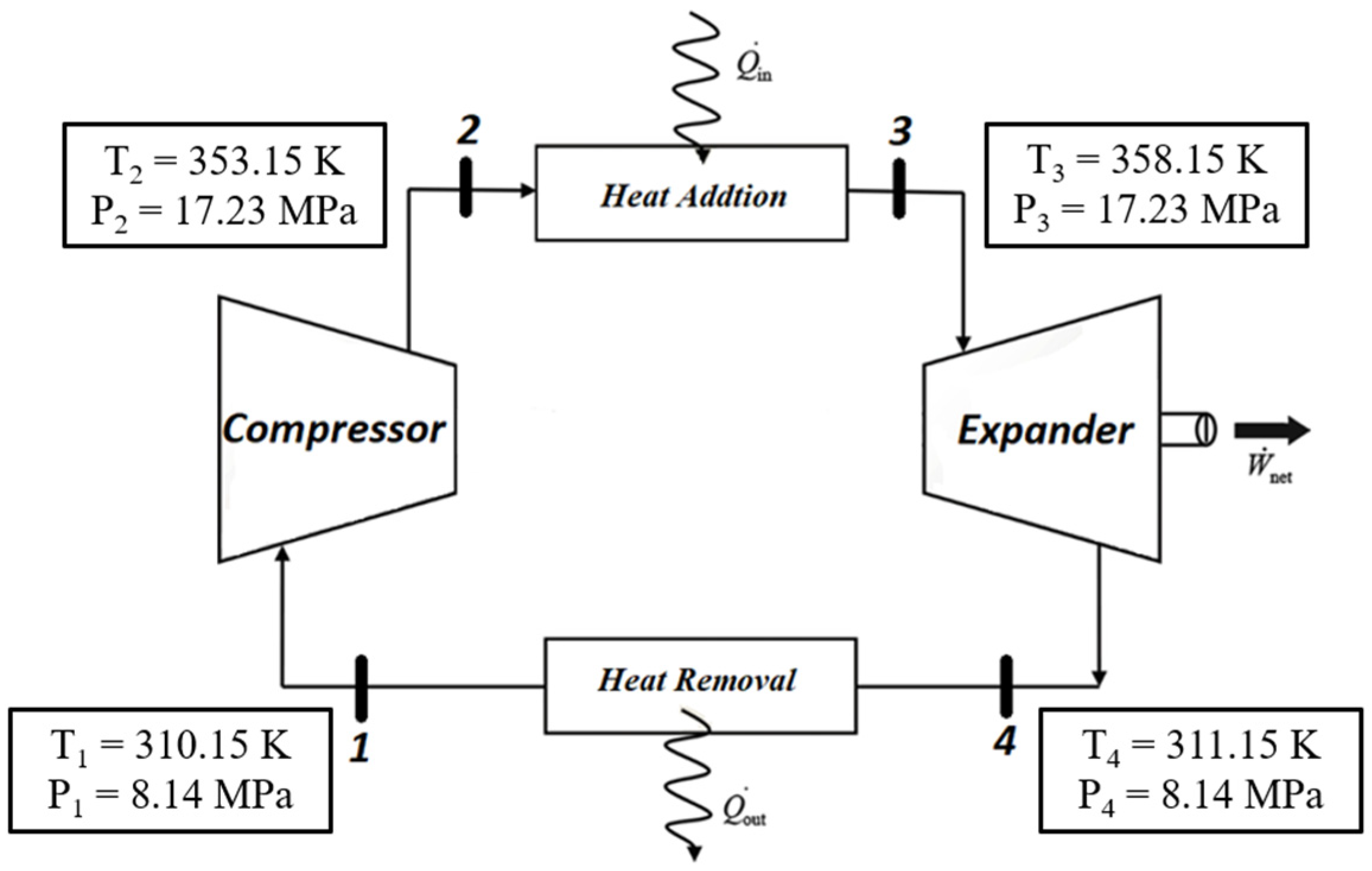
In designing and analyzing the sCO2 Brayton cycle, various cycle configurations have been investigated to be used for the current scope of research. It was determined that to avoid complexity and to obtain a proof of concept of operation, a simple Brayton cycle configuration would be chosen with four primary components. A simple Brayton cycle consists of a compressor, a heat source (heat addition into the system), an expansion section (the reciprocating piston expander), and a heat exchanger (heat dissipation from the system). Below, Figure 1 portrays the simplified schematic of the closed-loop sCO2 Brayton cycle. The energy transfers are positive in the direction of the arrows. Heat loss to the surroundings is neglected to simplify the cycle. Owing to the potential broad applications of portable, small-scale expander systems (portable generator, waste-heat recovery, disaster response, etc.), an ultra-small-scale system was the focus of the present effort.
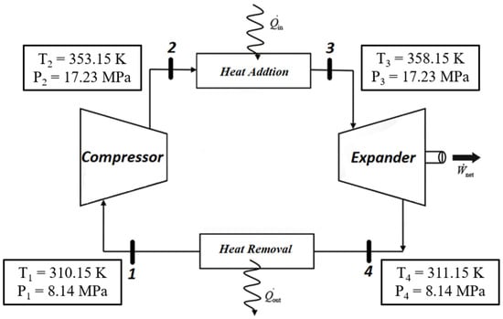
Figure 1.
Closed-loop sCO2 Brayton cycle.
The thermodynamic states of the sCO2 Brayton cycle were determined based upon the following criteria:
- Generate power at a kilowatt scale in the range of 1 to 10 kW (3412.14 to 34,121.4 Btu/h) for 5 min.
- Working fluid stays in the supercritical phase throughout the cycle.
- The heat source’s max heating capacity is 16.73 kW (57,085.13 Btu/h).
- The heat exchanger’s max cooling capacity is 13.5 kW (46,063.92 Btu/h).
- The cycle is considered a low-temperature heat source based on the above parameters.
3. Piston Expander Design
3.1. Piston Expander vs. Turbine Analysis
The expander of the closed-loop sCO2 Brayton Cycle serves as the most crucial part of the overall cycle, and a thorough analysis of the expander’s design was performed to elect between a turbine and a piston expander. The following equations were used to calculate the required rotor or the bore diameter, revolutions per minute (RPMs), and efficiency:
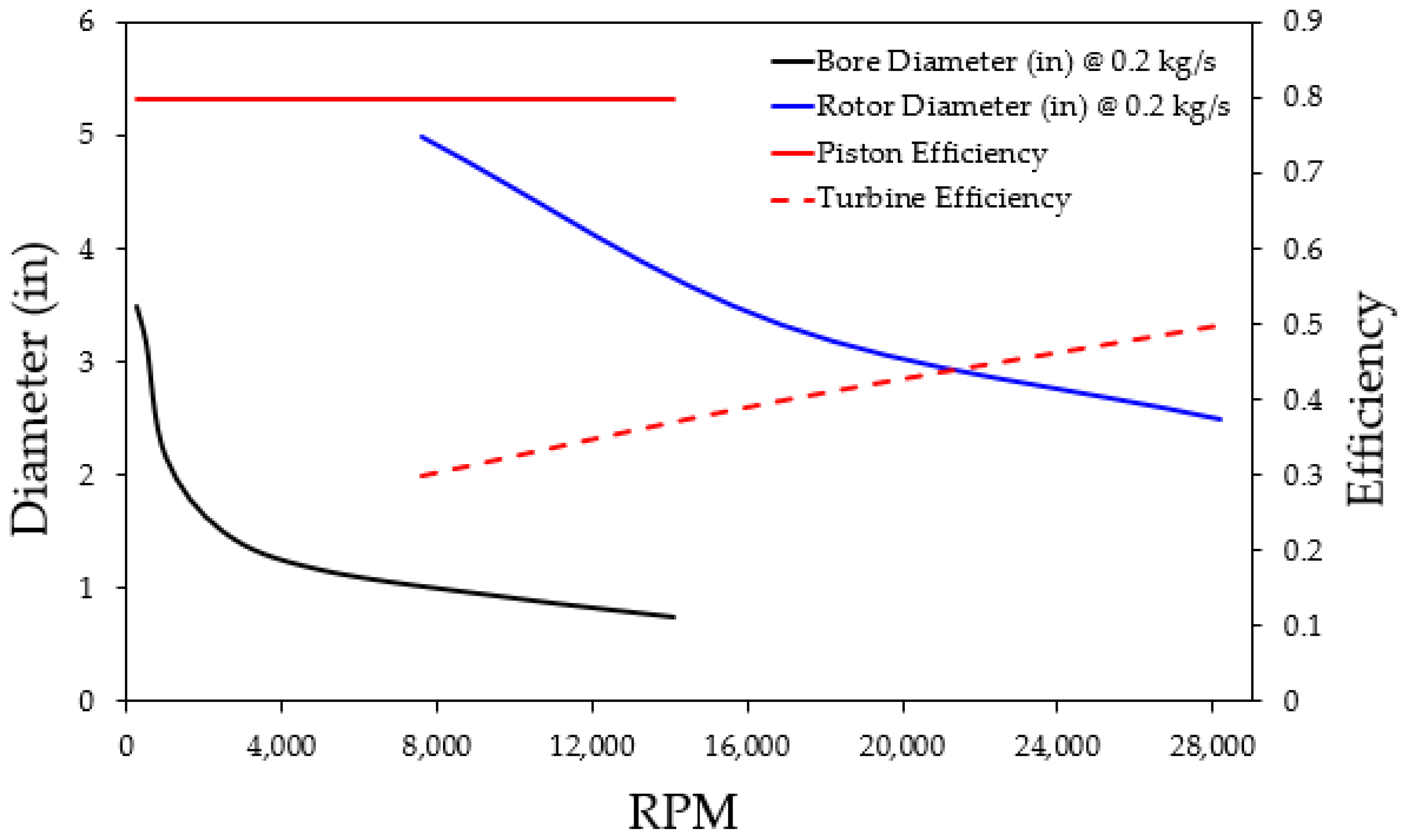
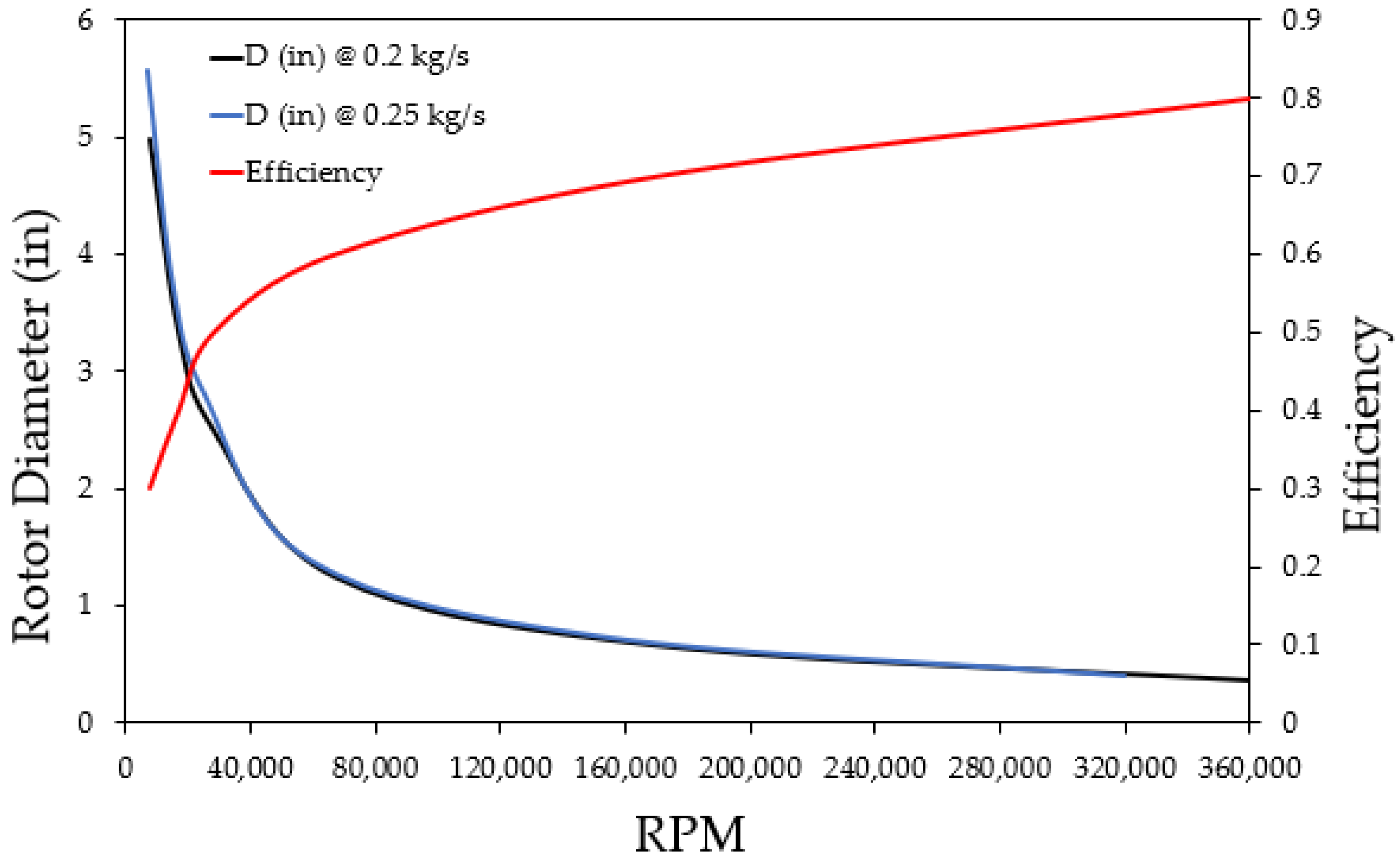
where the adiabatic head (Had) is calculated by utilizing the preliminarily determined properties of the fluid such as expansion ratio, inlet pressure, and inlet temperature. Equation (2) calculates the specific speed (Ns) over a range of RPMs using Had. To calculate the required diameter, an appropriate specific diameter (Ds) is selected based on the RPM ranges and the highest possible efficiency at that specific diameter by using the specific diameter vs. specific speed diagram for expanders in [20]. It is evident from the analysis seen in Figure 2 that the piston expander is more efficient (η = 0.8) than the turbine at low RPMs. The max efficiency of the turbine is 0.3 at about 7500 RPMs with the use of a 4.5″ (0.1143 m) turbine diameter. In order to achieve a comparable piston expander efficiency of 0.8, the required RPMs for the turbine significantly increase to about 360,000, as shown in Figure 3. However, the required diameter considerably drops to only 0.35″ (0.00889 m), which would potentially make the manufacturing process challenging. For this reason, a reciprocating piston expander is justified to be used over a turbine expander to produce an ample amount of torque for the paired electric generator. Figure 4 demonstrates the comparison of the bore diameter vs. RPM of the piston expander at two different mass flow rates. As the flow rate increases, the required bore diameter to maintain the efficiency at the same RPM also reduces; otherwise, efficiency drops. On the other hand, for the same bore diameter, if the speed increases, the efficiency drops, but if the speed decreases, the efficiency increases.
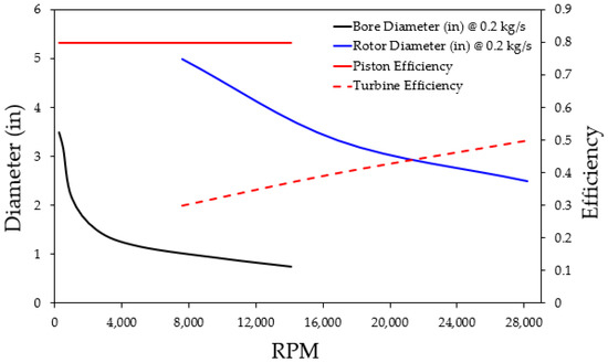
Figure 2.
Piston expander vs. turbine analysis.
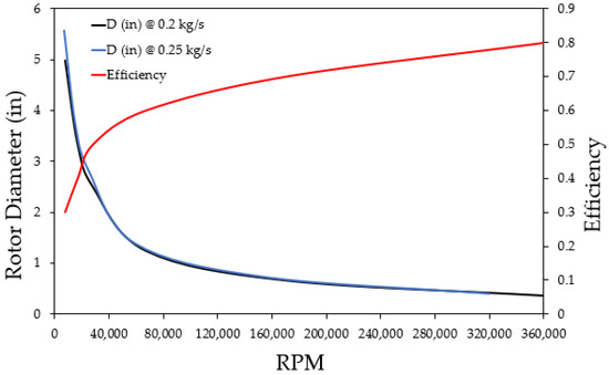
Figure 3.
Turbine efficiency vs. RPM.
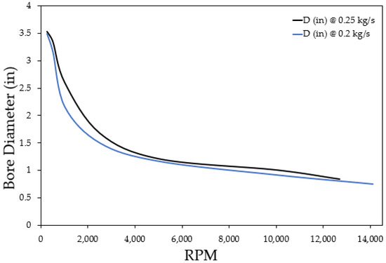
Figure 4.
Piston bore diameter vs. RPM at various flow rates.
3.2. Geometric Model
Finalized engine parameters of the engine are outlined in Table 1. Figure 5 shows the geometric model of these engine parameters. Based on Figure 4 the bore diameter of the piston expander was selected as 3 inches (0.0762 m). After multiple design iterations and ensuring that the expansion of the CO2 does not go under the supercritical phase while producing the desired power, the stroke length of the engine (L) was selected as 3.5 inches (0.0889 m). The engine’s connecting rod length (l) was selected as 6 inches (0.1524 m) to tune the engine to slow the piston speed departing from the Top Dead Center (TDC) since high pressure is applied to the piston at the beginning of the stroke for more net torque. These engine parameters become the baseline for the entire engine design. To calculate the crank radius (a) and the bore-to-stroke ratio (Rbs), the following equations are used [21]:
where “a” is the crank radius and “Rbs” is the bore-to-stroke ratio. The bore-to-stroke ratio less than one is called an ‘under-square’ engine design because of the longer stroke than bore size. An ‘under-square’ design is desired for the current application to generate higher torque. “B” is the bore diameter, and “L” is the stroke length. A bore-to-stroke ratio of 0.8 to 1.2 and connecting rod length-to-crank radius ratio of 3 to 3.5 are ideal for small and medium-sized engines [21]. The clearance volume (Vc) in Table 1 is the volume inside the cylinder when the piston is at TDC position, and the total volume (Vtot) is the volume inside the cylinder when the piston is at Bottom Dead Center (BDC).

Table 1.
sCO2 engine parameters.
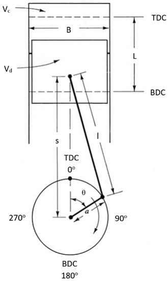
Figure 5.
Geometric model of the engine.
3.3. sCO2 Engine’s Main Components
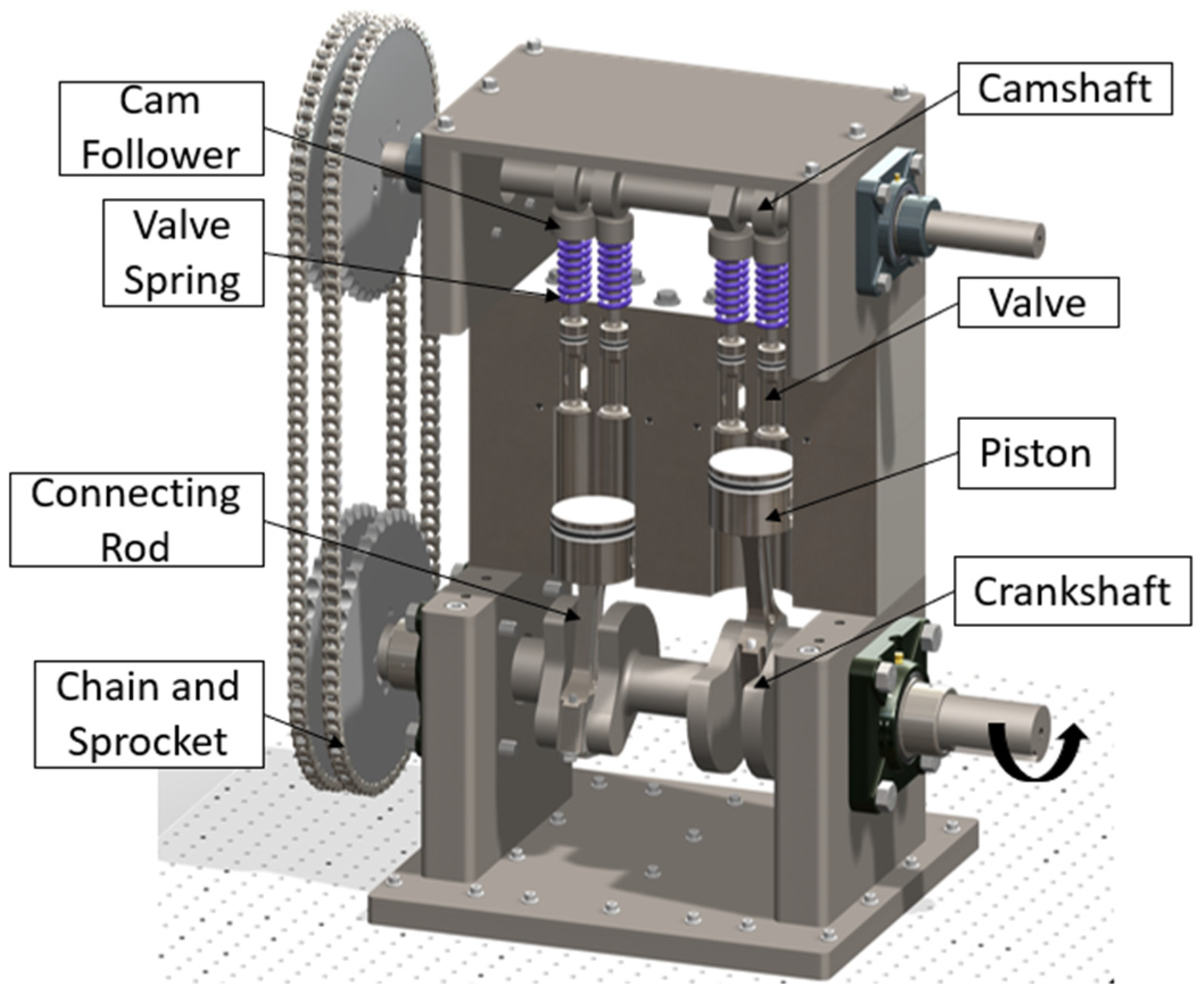
The sCO2 engine’s main components are shown in Figure 6. The sCO2 piston engine is a reciprocating expander with twin cylinders in an inline configuration. The engine’s components can be divided into powertrain and valvetrain. The reciprocating motion of the piston is converted into a rotational motion through the powertrain. The powertrain of the engine consists of pistons, connecting rods, crankshaft, valves, sprockets, and chains. The pressure at the face of the piston is converted to power to the crankshaft through the connecting rod. Therefore, the reciprocating work is now turned into rotational work. The sprockets are then used to transfer the energy to drive the camshaft and the generator through the crankshaft. A 1:1 gear ratio connects the camshaft and the crankshaft.
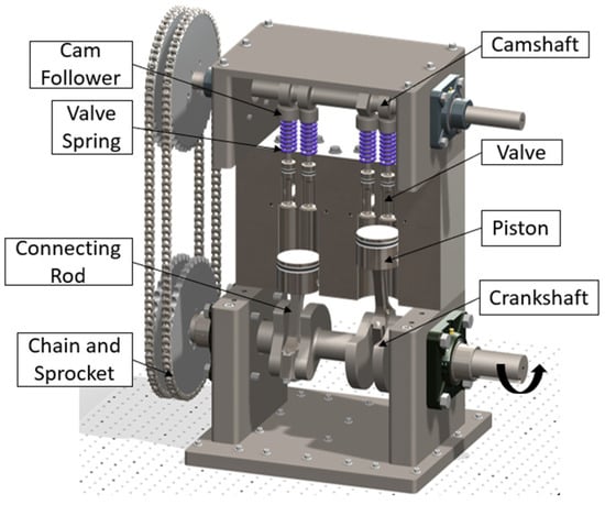
Figure 6.
Main components of the twin-cylinder sCO2 piston engine.
The intake and exhaust valves are timed with the pistons by developing the valvetrain. The valvetrain of the engine consists of the cam followers, camshaft, and valve springs. A poppet type of valve is used to supply and exhaust the sCO2 to and from the cylinders. Valves are held in a closed position using the valve springs, overcoming the ‘seat pressure’. The ‘seat pressure’ is the fluid force on the valve’s face that the valve spring overcomes to keep the valve in the closed position. The valve is pushed downward by the camshaft to open it. Therefore, the valve spring is compressed further, and the camshaft overcomes the spring’s resistive force to keep the valve open during the intake/exhaust duration. A flat-faced cam follower is attached at the top of the valve stem to allow the camshaft to push the valve down. The cam lobe on the camshaft makes contact with the cam follower to transfer rotary motion into linear motion. The designed intake valve timing ensures the optimum efficiency in producing power. Intake valve timing is designed using the cam lobes on the camshaft.
3.4. Working Principle
The sCO2 piston engine operates by intaking highly energized sCO2 into the cylinder during the power stroke. sCO2 pressure force pushes the piston down, overcoming friction losses to generate mechanical power at the crankshaft. The instantaneous volume inside the cylinder is calculated using Equations (6) and (7) based on the crank angle [21]:
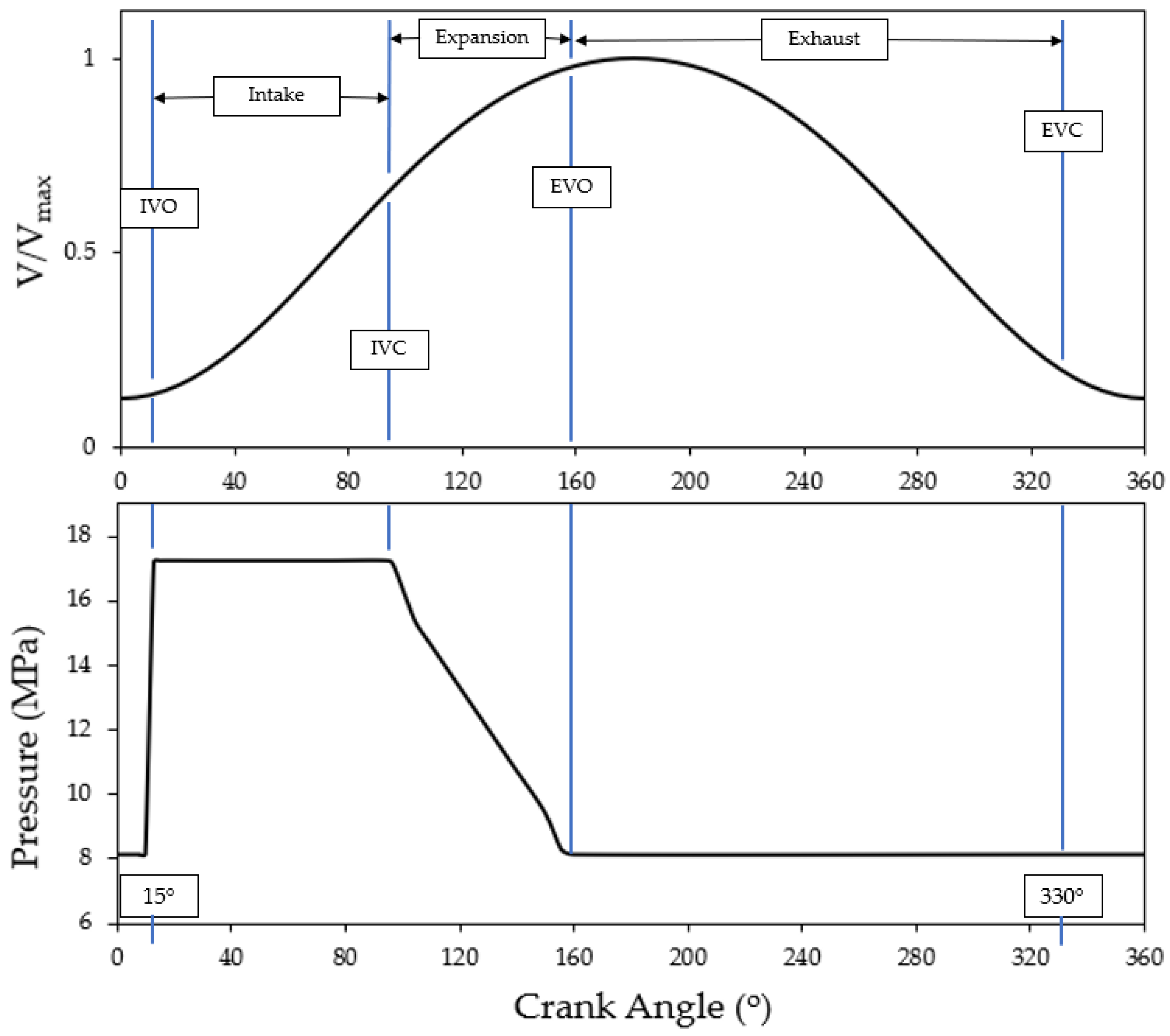
where “a” is the crank radius, “θ” is the crank angle, “l” is the connecting rod length, “s” is the distance between the piston pin center and the crank axis, “B” is the bore diameter, “Vc” is the clearance volume, and “V” is the instantaneous volume at a crank angle. The sequence of events which take place inside the sCO2 engine cylinder is illustrated in Figure 7, where V/Vmax and P are plotted against the crank angle for a fixed valve-timing engine. Both images in Figure 7 represent the changes in the volume and pressure inside the cylinder over the entire two strokes of the cycle. In Figure 7, IVO represents Intake Valve Opening, IVC represents Intake Valve Closing, EVO represents Exhaust Valve Opening, and EVC represents Exhaust Valve Closing.
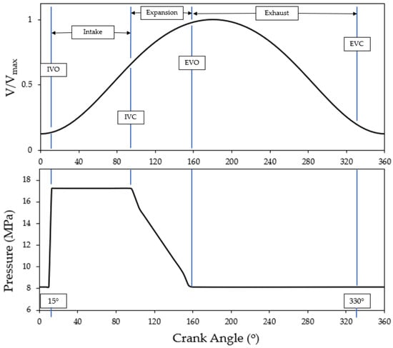
Figure 7.
Sequence of events in the sCO2 engine operating cycle.
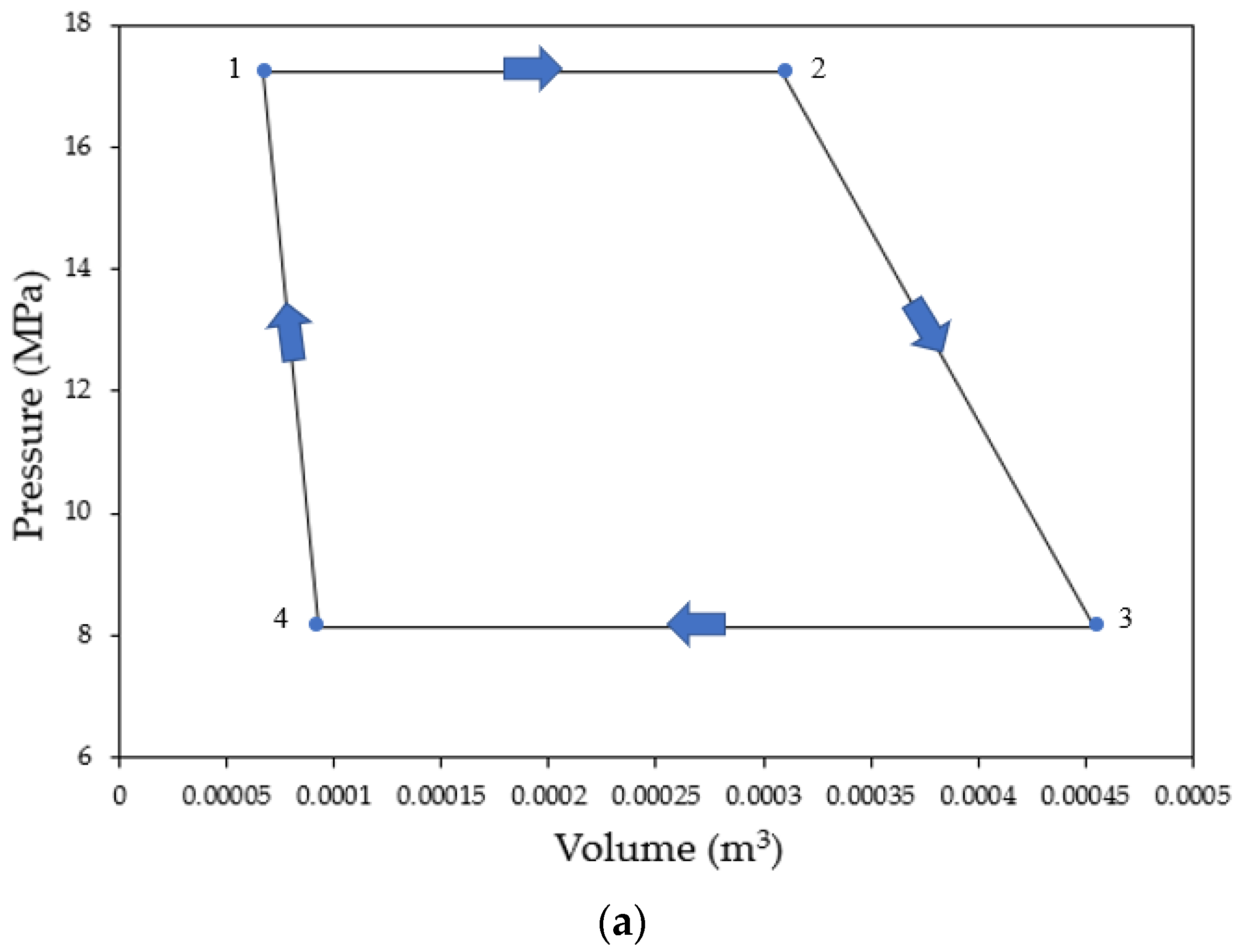
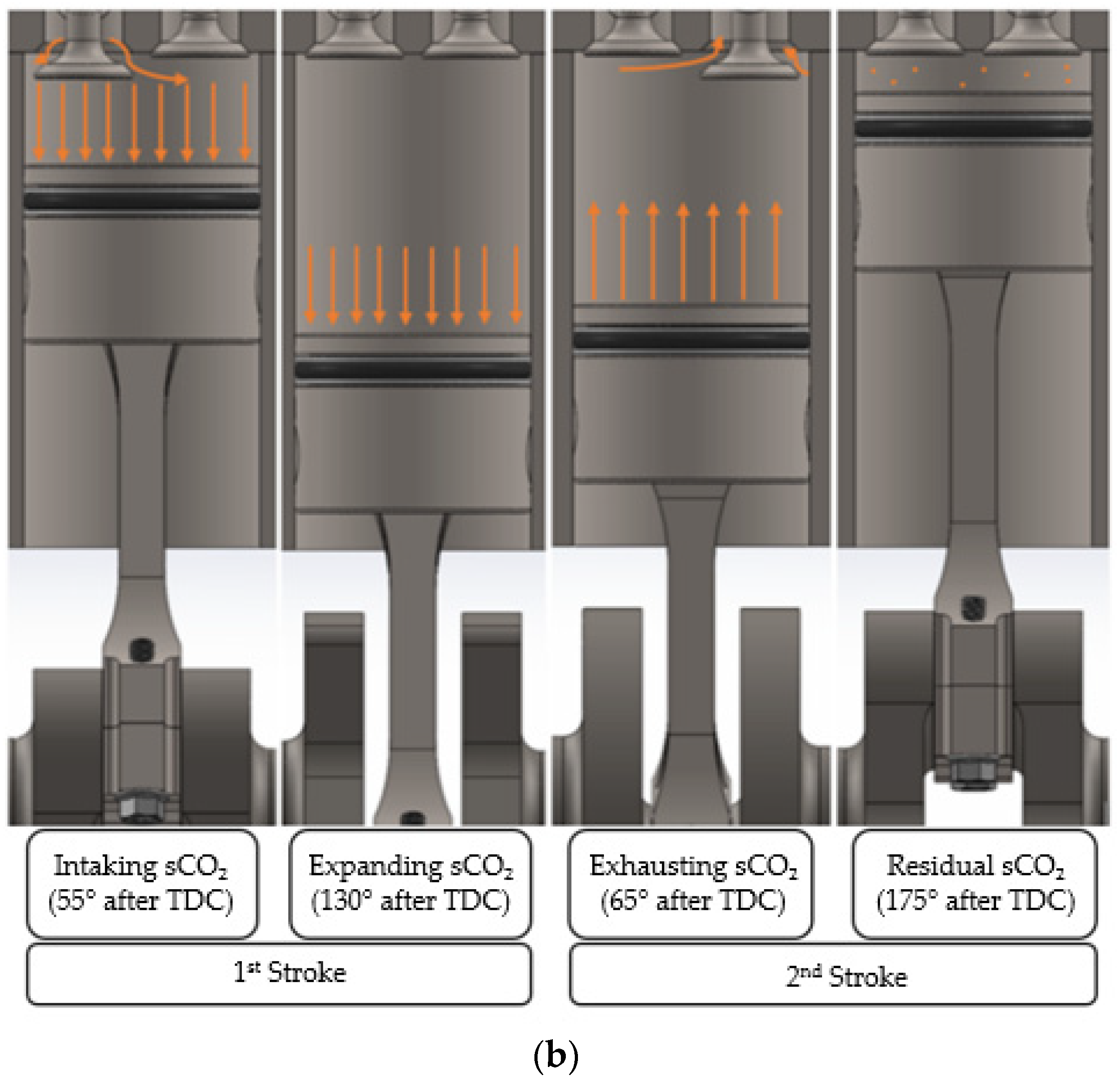
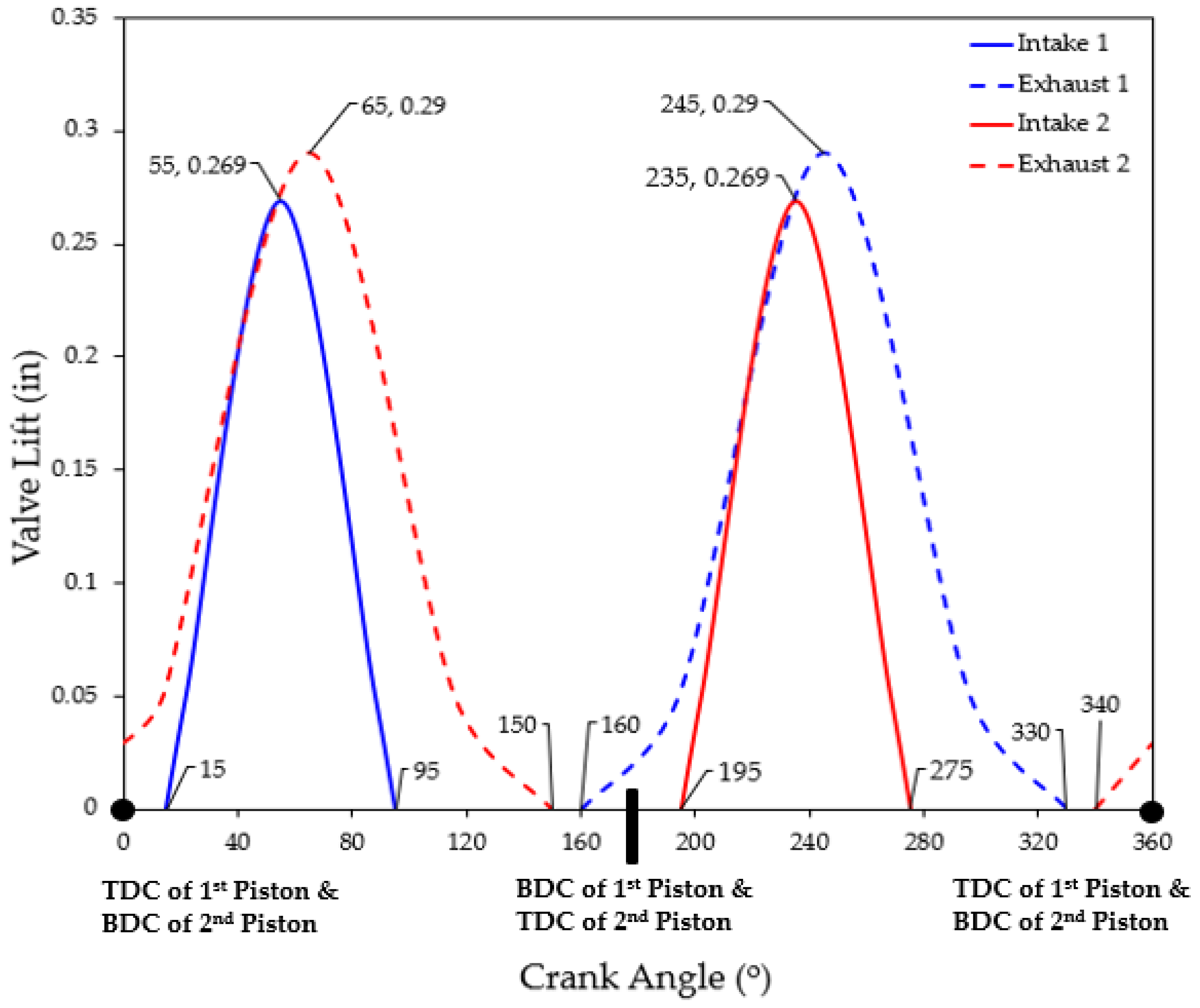
The expansion process of the fluid inside the cylinder can be visualized graphically, in Figure 8. The pressure changes of sCO2 inside the cylinder based on the changes in volume for an entire cycle are visualized in Figure 8. Processes 1 to 3 represent the power stroke, and the process from 3 and back to 1 represents the exhaust stroke. At position one, the piston is at about 15 degrees in crank angle after the TDC, and that is when the intake valve starts opening, and the piston begins its power stroke, traveling downwards. The pressurized sCO2 enters the cylinder at constant pressure until the intake valve is closed. The intake valve closed at position two, which is 95 degrees in crank angle after TDC. At position two, the inlet and exhaust valves are closed, and the expansion of the sCO2 begins. Expansion of sCO2 is the most critical part of the cycle as this is where the thermal energy is converted to mechanical energy. The piston continues its movement downwards from position two to position three by generating power and expanding sCO2. By assuming isentropic expansion, the pressure of the fluid is calculated at position three since the volume and entropy of sCO2 at this location are known. At position three, the exhaust valve starts opening at 160 degrees in crank angle after TDC, right before the piston reaches the BDC, and this is the beginning of the engine’s exhaust stroke. The pressure of the cylinder drops to close to the exhaust line pressure. Most of the sCO2 is exhausted during this process as the piston moves up and starts pushing the already expanded fluid out. At position four, the exhaust valve is closed at about 30 degrees in crank angle before the TDC. The inlet valve also remains closed for that period, during which the remaining fluid in the chamber is compressed and expanded until the piston is at position one again when the fresh sCO2 is again introduced in the cylinder, and the cycle then starts again. A visual representation of this valve timing and the valve lift with no valve overlap can be seen in Figure 9. The pressure of the residual fluid inside is lower than the incoming pressure of the fluid, so no detrimental effect is seen in the total power production. Additionally, work carried out by sCO2 on the piston in one cycle is the area enclosed in the cycle on the pressure vs. volume diagram.
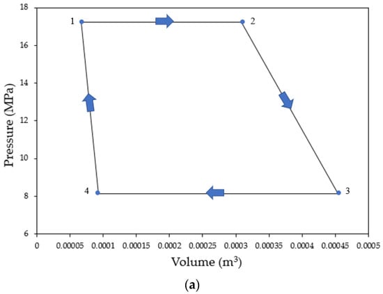
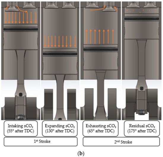
Figure 8.
Process of sCO2 inside the cylinder: (a) pressure vs. volume diagram and (b) visual representation.
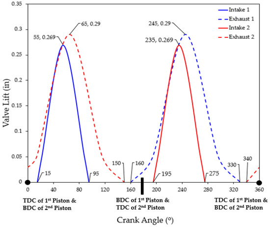
Figure 9.
Valve timing and lift profiles for a full crank rotation—360°.
Since the states of sCO2 at positions two and three are known, the corresponding enthalpy can be determined to calculate theoretical power. Power generated by the engine is 4.5 kW (6.03 HP), as explained in the cycle description section based on the inlet conditions. However, the power produced by the engine is scalable; that is, if a higher flow rate is supplied, higher power is generated. Adequate torque is required to turn the motor of the generator. Therefore, the RPMs of the engine must be calculated to calculate the average engine torque. To calculate RPMs, mean effective pressure (mep) is used. The mep of the engine is the hypothetical average pressure of sCO2 during the power stroke. The average pressure was determined as 1800 psi (12,410.5 kPa) based on the pressure vs. volume diagram on Figure 8. Equation (8) below can then be manipulated to calculate the rotational speed at the crankshaft [21]:
In the above equation, “mep” stands for the mean effective pressure of the engine in kPa, “nR” depends on the number of strokes the engine undergoes (two for four-stroke cycles; one for two-stroke cycles), “N” stands for the rotational speed in revolutions per second, “Vd” is the volume displaced by one cylinder per cycle in m3, and “P” is the total power generated in kW. In Equation (8), all the variables are known except the N, which is the rotational speed. By manipulating Equation (8), N was calculated to be about 18 RPMs. Since the power is known and RPMs are known using Equation (9), the engine’s average torque can be calculated [21]:
where “P” stands for power in Horsepower (HP), “T” is the torque in foot-pounds (ft-lbs), and “RPM” is the engine’s RPMs. Since the power being produced is about 4.5 kW (6.03 HP), the average torque is calculated to be 2433 ft-lbs (3299 Nm). It is important to point out that all these numbers are theoretical by assuming 100% isentropic efficiency and no friction loss. Additionally, the torque of the sCO2 piston engine remains constant over any range of RPMs because the supply of the sCO2′s pressure is independent of the RPMs.
4. Compressor
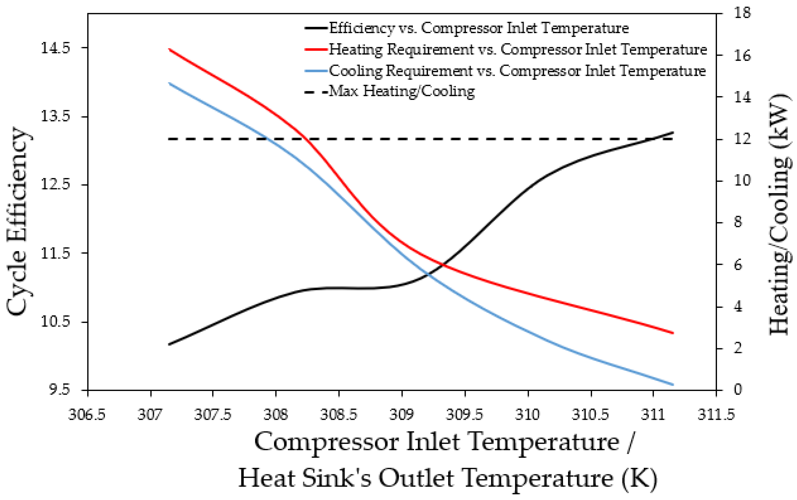
The compressor for the sCO2 power cycle is used to compress the fluid and control the flow rate. A flow rate of 0.2 kg/s was used to run the loop and meet the overall heating and cooling power requirements. In Figure 10, cycle efficiency is plotted vs. various compressor inlet temperatures, ranging from 307.15 to 311.15 K. It can be deducted from Figure 10 that as the inlet temperature increases, cycle efficiency increases, and the overall heating and cooling power required decreases. The figure also demonstrates the decrease of the compressor’s pumping capacity as the temperature increases. Therefore, a compressor inlet temperature of 310.15 K was selected.
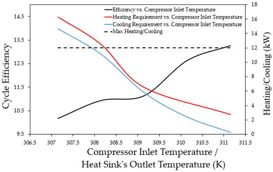
Figure 10.
Cycle efficiency vs. compressor’s inlet temperature.
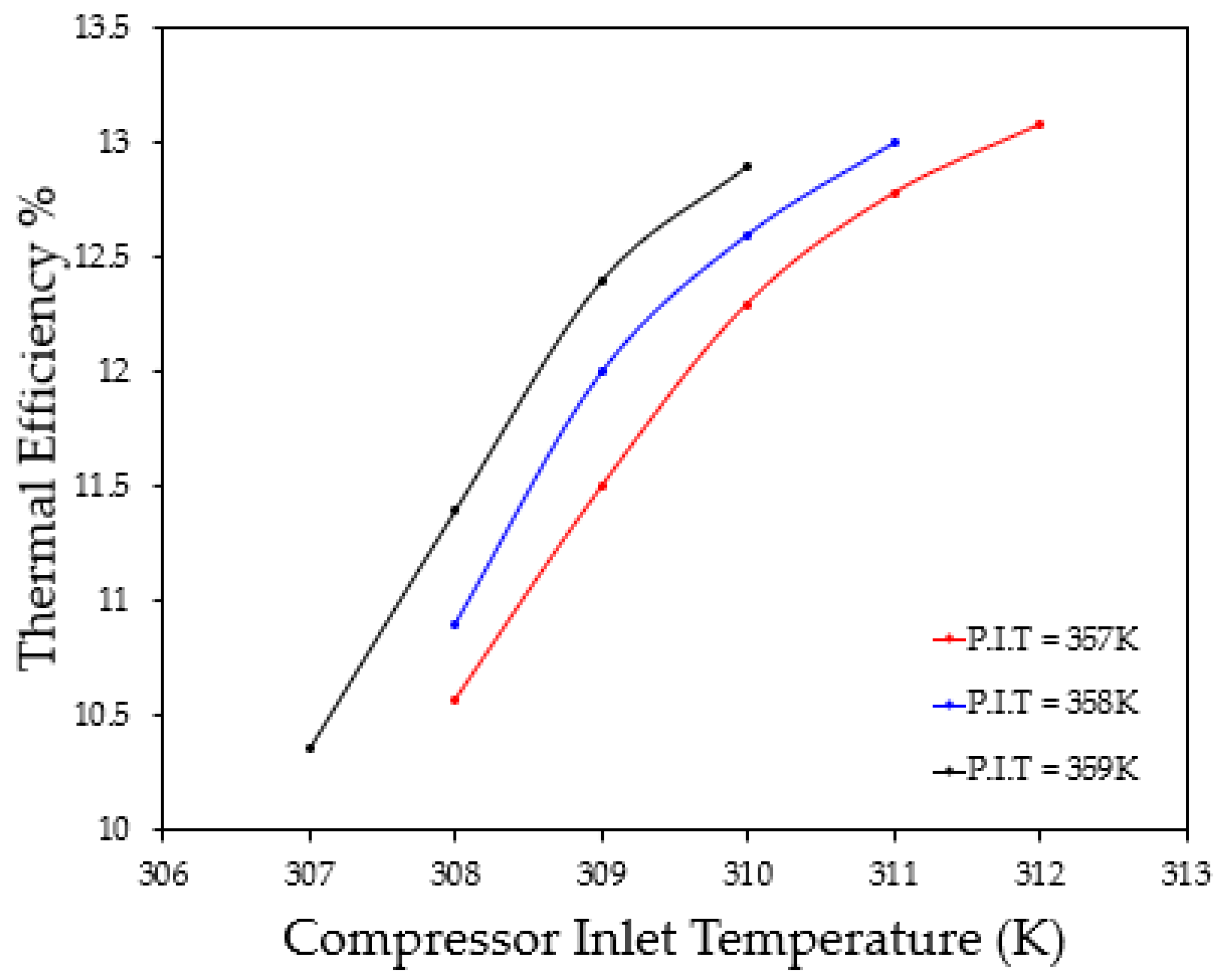
Figure 11 also details the thermal efficiency of the cycle with varying the compressor inlet temperature with a constant targeted piston inlet temperature (P.I.T). To achieve a thermal efficiency of 12.75%, a compressor inlet temperature of 310.15 K and a piston inlet temperature of 357.15–358.15 K were selected.
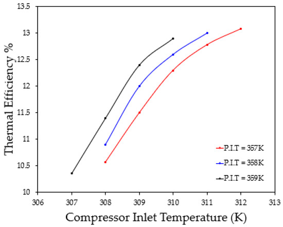
Figure 11.
Cycle thermal efficiency analysis.
5. Heat Source Design
The heat source consists of an extensive length of tubing wrapped with electrical heating tape. Using the heat tapes allowed for an inexpensive, controllable method of providing heat into the Brayton cycle while effectively utilizing the resources within the laboratory. A maximum of 19 heat tapes with a specified heat flux of 20.15 W/m2 (68.712 Btu/(h*m2) were used. Analyzing the anticipated drop in electrical power delivered to the heat tapes, an estimated maximum of 16.73 kW (57,085.13 Btu/h) of heat can be produced. In determining the dimensions of the tubing to be used with the heat tapes, pressure drop analysis was conducted, accounting for the frictional and heating effects of a compressible fluid. From [22], the following equations outline the method of obtaining the outlet pressure and enthalpy of the fluid, where f and q are the dimensionless friction and heating factors, respectively. “M” is the calculated Mach number of the fluid, γ is the specific heat ratio, “p” is the pressure of the fluid (Pa), and “h” is the enthalpy of the fluid (J/kg).
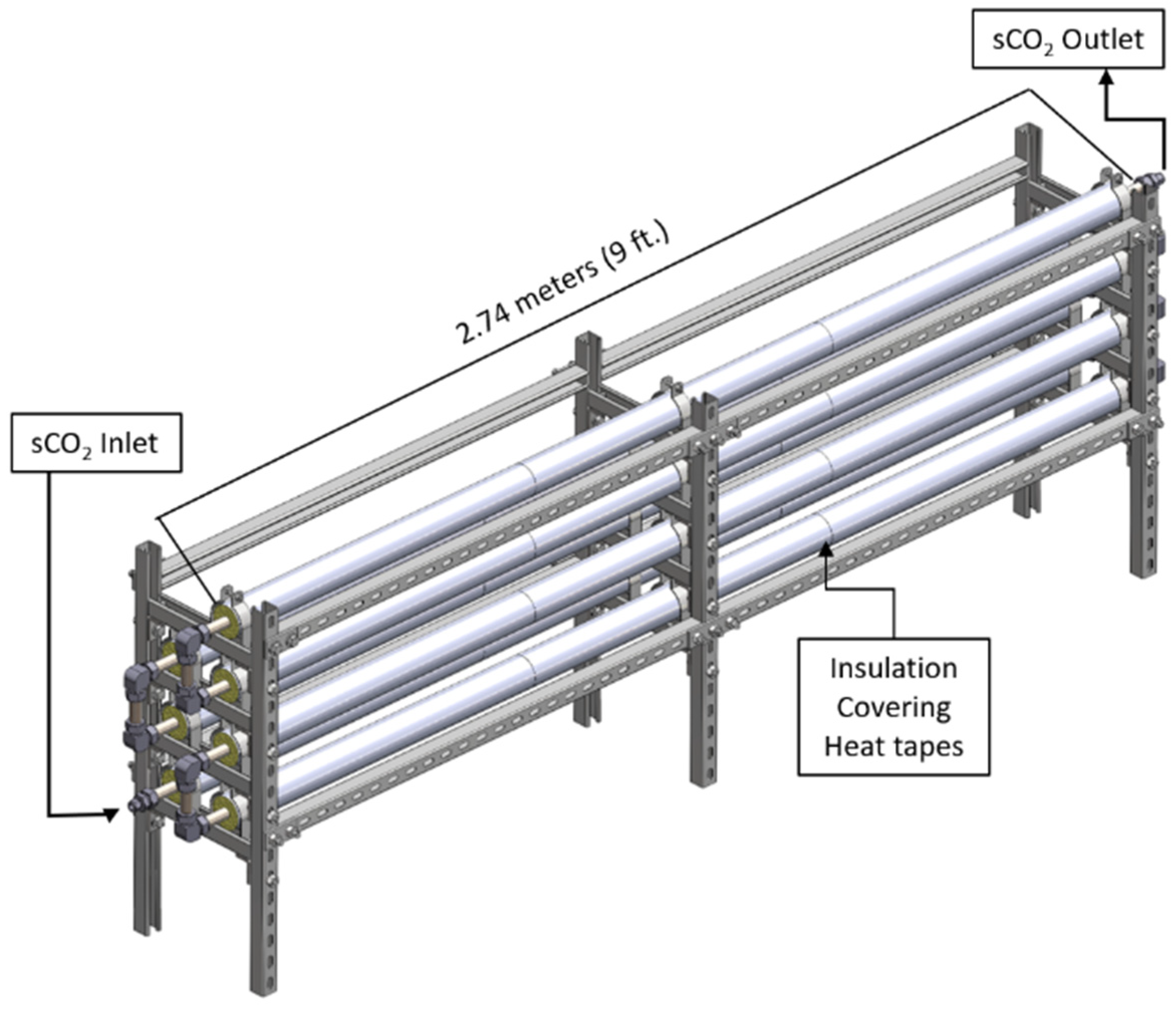
Comparing tube diameters of 1.27 cm (12.7 m), 1.905 cm (19.05 m), and 2.54 cm (25.4 m), the largest tube diameter of 2.54 cm (25.4 m) offered the smallest pressure drop across the length of the heat source (19.2 m or 63 feet). Separating the length of the heat source into equal segments, the final design consists of seven uniformly cut lengths of tubing (2.74 m or 9 feet), wrapped by heat tapes, and covered by insulation, as shown in Figure 12.

Figure 12.
Heat source design.
Monitoring the temperature of the fluid and the surface temperature of the heat source, thermocouples were installed at the inlet, outlet, and along the surface of the heat source. To control the amount of heat introduced into the flowing sCO2 to reach the desired inlet temperature to the piston expander, LabVIEW uses the outlet temperature and the heat source surface temperature as feedback to control the output of the heat tapes. Assuming that the heat tapes operate with a constant heat flux output, the surface temperature of the heat source can be monitored to estimate the temperature of the fluid at a specific section of the heat source [23]:
6. Heat Exchanger Design
The primary focus of the heat exchanger is to maintain the sCO2 temperature below 313.15 K at the inlet of the compressor while also minimizing the amount of pressure drop across the heat exchanger. The design of the heat exchanger will consist of a smooth-tubed, concentric heat exchanger configured in a counterflow orientation. sCO2 will flow through tubing surrounded by flowing cooling water. Then, 110 gallons (416.4 L) of cooling water will be used with a flow rate between 15 and 22 G.P.M. (56.78–83.28 L/min) through the heat exchanger. The capability to control the water flow rate through the heat exchanger allows the cycle to maintain an sCO2 temperature of 310.15 K at the inlet of the compressor.
The length of the heat exchanger required was estimated by using the log-mean temperature difference method [23,24]. To account for the variability in the properties of sCO2, the length of the heat exchanger was calculated using properties at the anticipated inlet, outlet, and mean temperatures of the heat exchanger, using the minimum flow rate of cooling water. In the analysis of the allowable pressure drop across the heat exchanger, Equations (7)–(10) are used comparing 0.635 cm (0.25 in.), 1.27 cm (0.50 in.), and 1.905 cm (0.75 in.) outer diameter tubing. Based upon cost effectiveness and meeting the allowable range of pressure drop across the heat exchanger, 1.27 cm (0.50 in.) tubing will be used.
With a total length of 11.34 m (37.2 feet), the heat exchanger can dissipate a maximum of 13.5 kW (46,063.91 Btu/h) of heat from the cycle with room-temperature cooling water. The length of the heat exchanger is separated into 4 separate lengths (3 equal lengths of 3.2 m or 10.5 feet). Long radius bends of tubing connect each section to minimize the amount of pressure drop caused by minor losses in the heat exchanger.
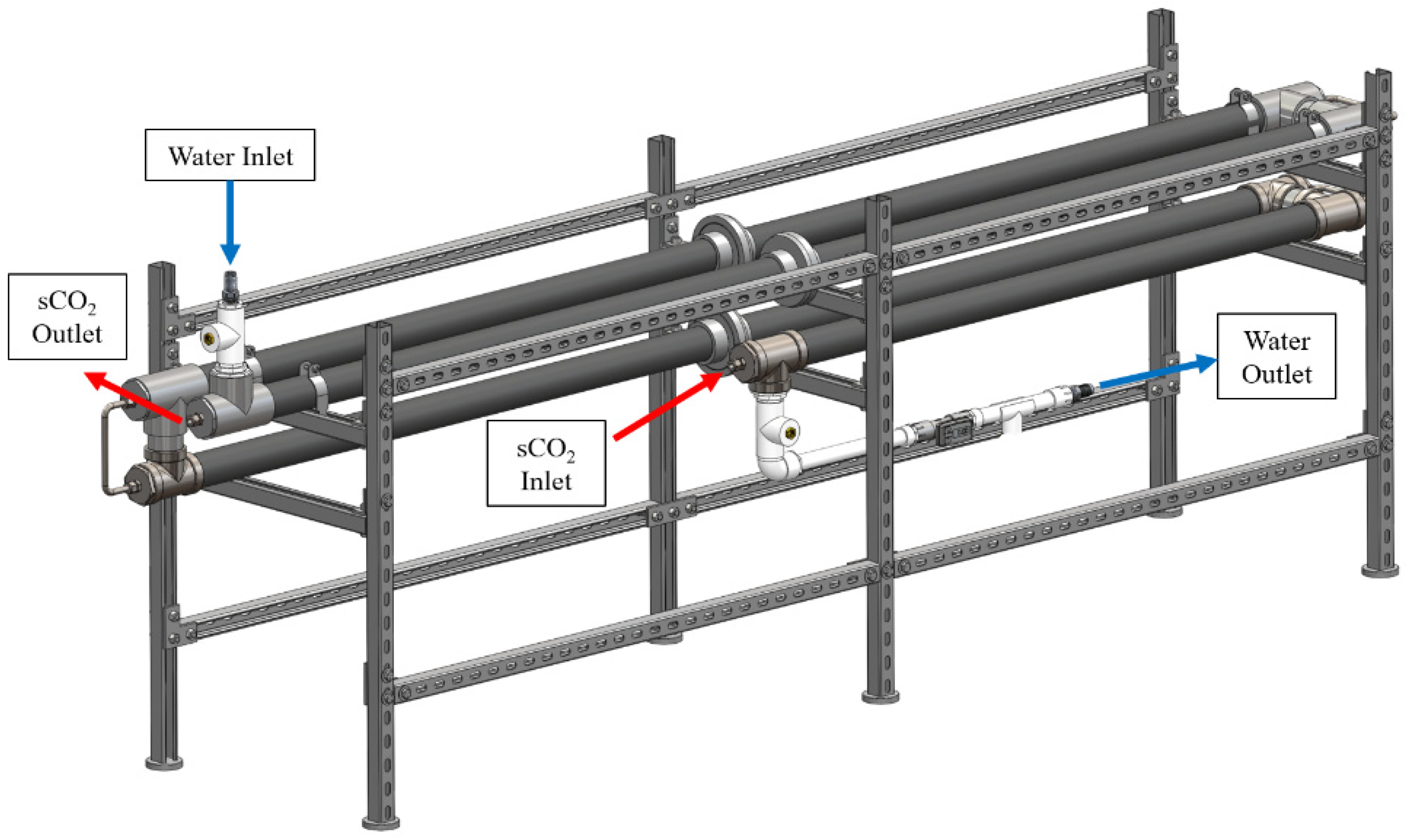
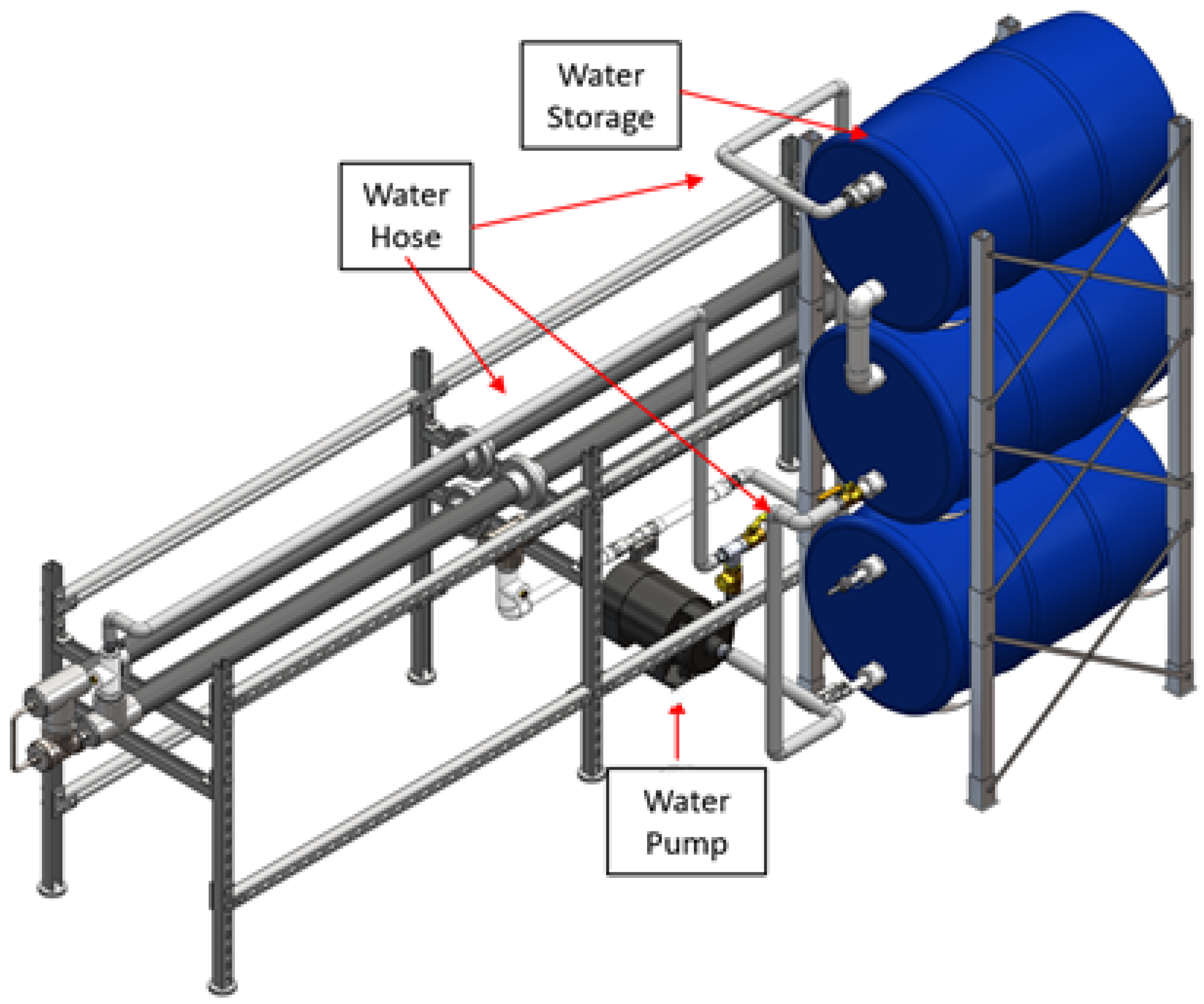
To maintain the inlet temperature of the compressor, thermocouples installed at the inlet and outlet of the heat exchanger, as shown in Figure 13, monitor the temperature of the cooling water and the sCO2. A water flow meter installed at the outlet of the heat exchanger provides feedback for the control loop of the variable frequency drive (VFD) and water pump of the cooling loop. With 110 gallons (416.4 L) of cooling water to be used, the operational time of the cycle is largely dependent on the amount of heat that is required to be dissipated. Figure 14 demonstrates the heat exchanger design with the cooling loop.
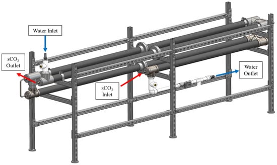
Figure 13.
Heat exchanger design.

Figure 14.
Heat exchanger with cooling loop.
Piping and Instrumentation Diagram (P&ID)
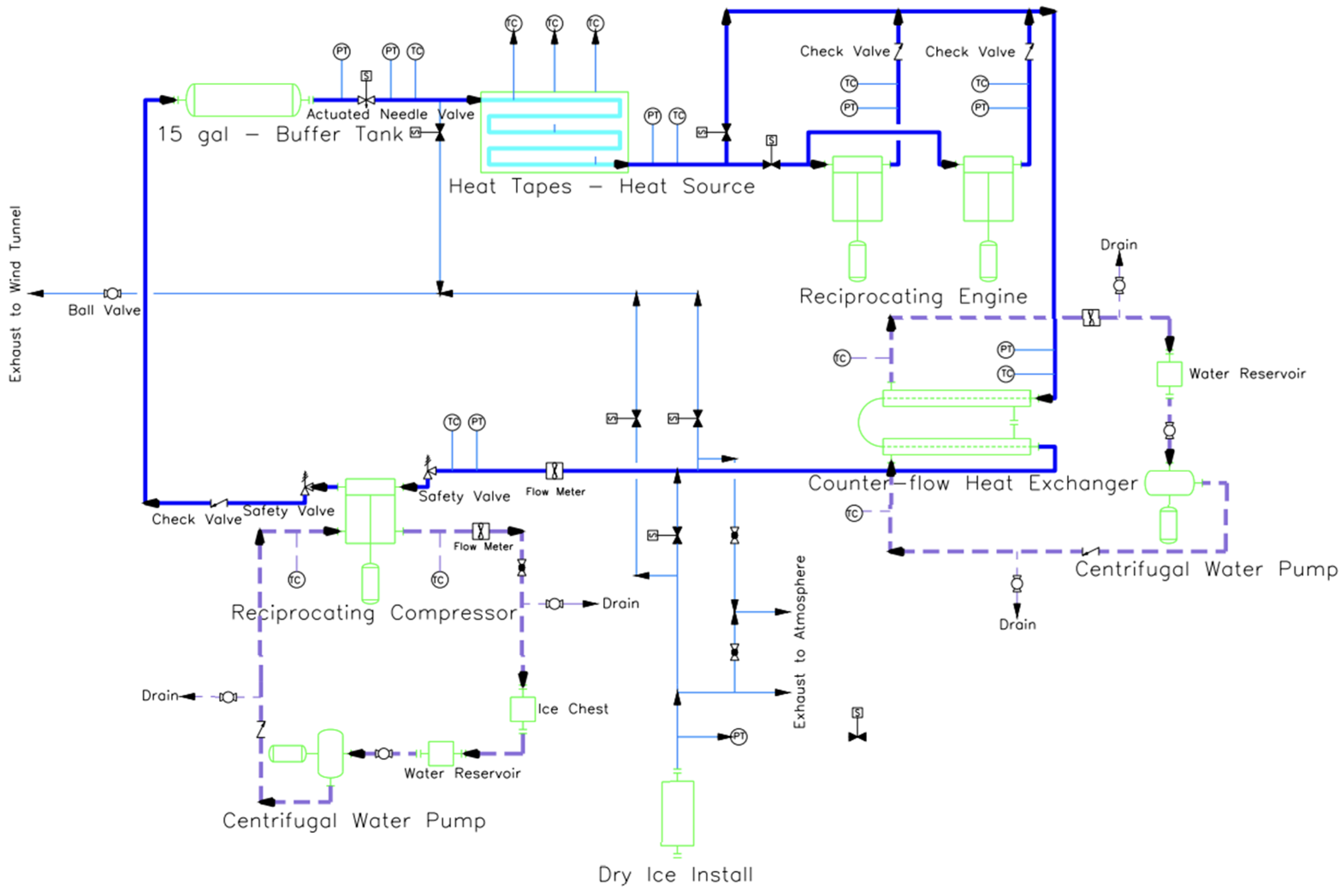
To monitor the operation of the cycle, thermocouples and pressure transducers will be placed between each component to map the states of the working fluid. Thermocouples are placed in the cooling loops of the heat exchanger and compressor to monitor the temperature of the cooling water. Control loops use the temperature and pressure readings in the cycle as feedback parameters for determining the compressor’s cycling rate, heat source’s heat addition, and the heat exchanger’s heat dissipation. Solenoid valves and hand valves are installed to control the direction of the flowing sCO2 during the process of filling and purging the system of sCO2. An overview of the system’s P&ID is shown in the schematic of Figure 15.

Figure 15.
sCO2 loop P&ID schematic.
7. Conclusions and Future Work
With the development of a small-scale power cycle, here, the team has employed a closed-loop, indirect-fired, sCO2 Brayton cycle. The simple Brayton cycle consists of a compressor, a heat source (heat addition to the system), an expansion section (sCO2 piston engine), and a heat exchanger (heat dissipation from the system). The sCO2 piston engine is a reciprocating expander with twin cylinders in an inline configuration. A piston expander is viably compatible with the small-scale power cycle, producing high isentropic efficiencies at slow rotational speeds with an ample magnitude of torque for the paired electric generator.
The sCO2 piston operates by intaking highly energized sCO2 into the cylinder during the power stroke. The pressure force of the fluid pushes the piston down, overcoming all frictional losses to generate mechanical power at the crankshaft. Based upon the inlet conditions to the sCO2 piston engine provided by the cycle, the engine can produce 4.5 kW (6.03 HP) of power with a mass flow rate of 0.2 kg/s. However, the amount of power produced by the engine is scalable, and more power is generated with higher mass flow rates.
The heat source consists of an extensive length of tubing wrapped with electrical heating tape. Accounting for the anticipated drop in electrical power delivered to the heat tapes, it is estimated that the heat source can produce a maximum of 16.73 kW (57,085.13 Btu/h) of heat. The primary focus of the heat exchanger is to maintain the sCO2 temperature below 313.15 K at the inlet of the compressor while also minimizing the amount of pressure drop across the heat exchanger. The design of the heat exchanger consists of a smooth-tubed, concentric heat exchanger configured in a counterflow orientation. The heat exchanger can dissipate a maximum of 13.5 kW (46,063.91 Btu/h) of heat from the cycle with room-temperature cooling water. Under isentropic conditions, a compressor inlet temperature of 310.15 K and a piston inlet temperature of 357.15–358.15 K, the overall thermal efficiency of the cycle was estimated to be 12.75%.
Future work for the cycle includes testing and running the cycle to determine the isentropic efficiencies of the compressor and the sCO2 piston engine. System testing will provide empirical data to compare to the theoretical calculations that were conducted for the design of the sCO2 piston engine, the heat source, and the heat exchanger to help improve future work on the small-scale sCO2 Brayton cycle.
Author Contributions
Conceptualization, R.C.P., D.C.B. and G.P.D.; methodology, R.C.P. and D.C.B.; formal analysis, R.C.P., D.C.B. and G.P.D.; writing—original draft preparation, R.C.P. and D.C.B.; writing—review and editing, A.A. and C.S.C.; visualization, R.C.P. and D.C.B.; supervision, C.S.C.; project administration, C.S.C. All authors have read and agreed to the published version of the manuscript.
Funding
This project and the preparation of this report were funded in part by funds provided by CPS Energy through an agreement with The University of Texas at San Antonio.
Institutional Review Board Statement
Not applicable.
Informed Consent Statement
Not applicable.
Data Availability Statement
Not applicable.
Conflicts of Interest
The authors declare no conflict of interest.
References
- U.S. Energy Information Administration—EIA. Independent Statistics and Analysis. Electricity in the U.S. Available online: https://www.eia.gov/energyexplained/electricity/electricity-in-the-us.php (accessed on 1 August 2021).
- Table 7.2a Electricity Net Generation: Total (All…—EIA). Available online: https://www.eia.gov/totalenergy/data/monthly/pdf/sec7_5.pdf (accessed on 1 August 2021).
- Brun, K.; Friedman, P.; Dennis, R. Fundamentals and Applications of Supercritical Carbon Dioxide (SCO2) Based Power Cycles; Elsevier Science & Technology: Cambridge, MA, USA, 2017. [Google Scholar]
- Xu, J.; Liu, C.; Sun, E.; Xie, J.; Li, M.; Yang, Y.; Liu, J. Perspective of S−CO2 Power Cycles. Energy 2019, 186, 115831. [Google Scholar] [CrossRef]
- Persichilli, M.; Kacludis, A.; Zdankiewicz, E.; Held, T. Supercritical CO2 power cycle developments and commercialization: Why sCO2 can displace steam. Power-Gen India Cent. Asia 2012, 2012, 19–21. [Google Scholar]
- Li, M.-J.; Zhu, H.-H.; Guo, J.-Q.; Wang, K.; Tao, W.-Q. The Development Technology and Applications of Supercritical CO2 Power Cycle in Nuclear Energy, solar energy and other energy industries. Appl. Therm. Eng. 2017, 126, 255–275. [Google Scholar] [CrossRef]
- Dostal, V.; Hejzlar, P.; Driscoll, M.J. The supercritical carbon dioxide power cycle: Comparison to other advanced power cycles. Nucl. Technol. 2006, 154, 283–301. [Google Scholar] [CrossRef]
- Klemencic, G.; Flegkas, S.; Werner, A.; Haider, M.; Leibinger, H. Comparison of conventional and CO2 power generation cycles for waste heat recovery. In Proceedings of the 5th International Symposium—Supercritical CO2 Power Cycles, San Antonio, TX, USA, 28–31 March 2016. [Google Scholar]
- Dostal, V. A Supercritical Carbon Dioxide Cycle for Next Generation Nuclear Reactors. Ph.D. Thesis, Massachusetts Institute of Technology, Cambridge, MA, USA, 2004. [Google Scholar]
- Allam, R.J.; Palmer, M.R.; Brown, G.W., Jr.; Fetvedt, J.; Freed, D.; Nomoto, H.; Jones, C., Jr. High efficiency and low cost of electricity generation from fossil fuels while eliminating atmospheric emissions, including carbon dioxide. Energy Procedia 2013, 37, 1135–1149. [Google Scholar] [CrossRef] [Green Version]
- Allam, R.J.; Fetvedt, J.E.; Forrest, B.A.; Freed, D.A. The oxy-fuel, supercritical CO2 Allam Cycle: New cycle developments to produce even lower-cost electricity from fossil fuels without atmospheric emissions. In Turbo Expo: Power for Land, Sea, and Air; American Society of Mechanical Engineers: New York, NY, USA, 2014; Volume 45660, p. V03BT36A016. [Google Scholar]
- Allam, R.; Martin, S.; Forrest, B.; Fetvedt, J.; Lu, X.; Freed, D.; Manning, J. Demonstration of the Allam Cycle: An update on the development status of a high efficiency supercritical carbon dioxide power process employing full carbon capture. Energy Procedia 2017, 114, 5948–5966. [Google Scholar] [CrossRef]
- Weiland, N.; Shelton, W.; Shultz, T.; White, C.W.; Gray, D. Performance and Cost Assessment of a Coal Gasification Power Plant Integrated with a Direct-Fired SCO2 Brayton Cycle; National Energy Technology Laboratory (NETL): Pittsburgh, PA, USA, 2017. [CrossRef]
- Yoon, H.J.; Ahn, Y.; Lee, J.I.; Addad, Y. Potential advantages of coupling supercritical CO2 Brayton cycle to water cooled small and medium size reactor. Nucl. Eng. Des. 2012, 245, 223–232. [Google Scholar] [CrossRef]
- Turchi, C.S.; Ma, Z.; Neises, T.W.; Wagner, M.J. Thermodynamic study of advanced supercritical carbon dioxide power cycles for concentrating solar power systems. J. Sol. Energy Eng. 2013, 135, 041007. [Google Scholar] [CrossRef]
- Iverson, B.D.; Conboy, T.M.; Pasch, J.J.; Kruizenga, A.M. Supercritical CO2 Brayton Cycles for solar-thermal energy. Appl. Energy 2013, 111, 957–970. [Google Scholar] [CrossRef] [Green Version]
- Ho, C.K.; Carlson, M.; Garg, P.; Kumar, P. Technoeconomic analysis of alternative solarized S-CO2 Brayton Cycle Configurations. J. Sol. Energy Eng. 2016, 138, 051008. [Google Scholar] [CrossRef]
- Kimzey, G. Development of a Brayton Bottoming Cycle Using Supercritical Carbon Dioxide as the Working Fluid; Electric Power Research Institute, University Turbine Systems Research Program, Gas Turbine Industrial Fellowship: Palo Alto, CA, USA, 2012. [Google Scholar]
- Chen, Y.; Lundqvist, P.; Platell, P. Theoretical research of carbon dioxide power cycle application in automobile industry to reduce vehicle’s fuel consumption. Appl. Therm. Eng. 2005, 25, 2041–2053. [Google Scholar] [CrossRef]
- Balje, O.E. Turbomachines: A Guide to Design, Selection, and Theory; Wiley-Interscience: New York, NY, USA, 1981. [Google Scholar]
- Heywood, J.B. Internal Combustion Engine Fundamentals; McGraw-Hill Education: New York, NY, USA, 2018. [Google Scholar]
- Kundu, P.K.; Dowling, D.R.; Cohen, I.M. Fluid Mechanics; Elsevier: Amsterdam, The Netherlands, 2016. [Google Scholar]
- Bergman, T.L.; Lavine, A.S. Fundamentals of Heat and Mass Transfer; John Wiley and Sons: Hoboken, NJ, USA, 2017. [Google Scholar]
- Lienhard, J.H.; Lienhard, J.H. A Heat Transfer Textbook; Dover Publications: Mineola, NY, USA, 2020. [Google Scholar]


Publisher’s Note: MDPI stays neutral with regard to jurisdictional claims in published maps and institutional affiliations. |
© 2022 by the authors. Licensee MDPI, Basel, Switzerland. This article is an open access article distributed under the terms and conditions of the Creative Commons Attribution (CC BY) license (https://creativecommons.org/licenses/by/4.0/).