Abstract
The technology of a pulsed detonation gun for gasification of organic waste with ultra-superheated steam has been experimentally demonstrated for the first time. Experiments were performed on natural gas conversion as well as on the gasification of liquid (waste machine oil) and solid (wood sawdust) waste by hot detonation products of natural gas–oxygen mixture at a frequency of detonation pulses f = 1 Hz. Periodic release of detonation products to a 100 L flow reactor provided a time-averaged mean temperature and pressure in the reactor at about 1200 K and 0.1 MPa. It is shown that the technology of a pulsed detonation gun can provide complete (100%) natural gas conversion to syngas containing H2 and CO with a H2/CO ratio of 1.25. During the gasification of liquid and solid wastes, the total volume fraction of combustible gases (H2, CO, and CH4) in the product syngas was 80 and 65% with H2/CO ratios of 0.8 and 0.5, respectively. Comparison of the experiments on natural gas conversion and liquid/solid organic waste gasification under the same conditions at f = 1 Hz showed that the composition of the product syngas in terms of H2 and CO content almost did not depend on the type of used feedstock. The estimated ideal energy gain defined as the ratio of the total energy of product syngas to the energy spent in its production from dry wood sawdust is about 4.6, i.e., the pulsed detonation technology of biomass gasification is economically very attractive.
1. Introduction
Thermal gasification of organic waste is the process of waste conversion into a gaseous state due to the supply of a gasifying agent and heat to allow for endothermic thermal decomposition, dehydrogenation, water–gas, Boudouard, steam and dry reforming, etc., reactions, as well as exothermic oxidation, partial oxidation, and hydrogasification reactions. The gasifying agent is usually air, oxygen, steam, or carbon dioxide. The most valuable gasification product is syngas containing, on the one hand, H2 and CO, and, on the other hand, non-condensable lower hydrocarbons such as CH4, C2H6, etc., and CO2. Syngas is used to produce various chemicals (methanol, ammonia, etc.) and motor fuels. It exhibits a low heating value (LHV) of 15–17 MJ/kg (12–16 MJ/nm3). The LHVs of its main combustible constituents are 10.8 MJ/nm3 (H2), 12.6 MJ/nm3 (CO), and 35.8 MJ/nm3 (CH4). By-products of gasification are char and tar, which can store a significant part of the carbon contained in the waste. The quality of syngas is higher the more H2 and CO it contains, and their relative content can vary over a wide range determined by many factors. The efficiency of the gasification process is higher the greater the syngas yield and the less carbon remains in by-products (the higher the carbon conversion). Modern technologies for the thermal gasification of organic wastes are presented in monographs [1,2]. Other methods used for the gasification of organic wastes include supercritical water gasification (at above 374 °C and 22.1 MPa) [3] and biological methods based, e.g., on fermentation [4].
All thermal waste gasification technologies can be divided into two groups: low-temperature (800–1300 K) and high-temperature (above 1500 K). Low-temperature gasification technologies are characterized by relatively low-quality syngas due to high content of tar (up to 27%wt dry basis, d.b.) and CO2 (up to 30%vol d.b.); low gasification efficiencies due to high char residues (up to 40%wt d.b.); difficult in situ gas quality control due to the need in long residence times of feedstock in the reaction zone (up to 100 min); and low process efficiency due to low gas yields (below 90%wt d.b.), high tar and char contents and partial use of syngas (together with product char) for the production of heat required for gasification [5]. Currently, for improving the carbon conversion efficiency, efforts are directed on increasing feedstock reactivity by adding various catalysts, as well as preprocessing of feedstock and postprocessing of product syngas [6,7]. High-temperature gasification provides high-quality syngas due to negligible or low content of tar (less than 1 g/nm3) and CO2 (less than 6%vol d.b.); high gasification efficiencies with carbon conversion efficiency attaining 100% due to negligible or small tar and char residues; easy in situ gas quality control due to relatively short residence times of feedstock (less than 5–10 min) in the reaction zone; and high process efficiency due to the use of electric or solar energy for the production of heat required for gasification [8]. Currently, the most promising high-temperature technologies include electric arc [9,10] and microwave [11] plasma technologies, as well as detonation technologies [12]. As for the plasma technologies, they require huge electricity consumption and special structural materials and/or refractory linings for gasifier walls. In addition, feedstock gasification in plasma reactors mainly occurs at temperatures of 1500–2200 K, so the gas–plasma transition turns out to be an unnecessary and energy-consuming intermediate stage. As for the detonation technologies, they provide similar gasification temperatures (above 2200 K) without gas–plasma transition but do not need special structural materials and/or refractory linings for gasifier walls. The first mentions of detonation technologies go back to [13,14], where pulverized coal gasification was studied in a single-pulse detonation-induced flow with the coal particle residence time in the detonation products ranging from 1 to 15 ms. Despite too few tests being performed for conclusive statements, combined yields of CO and CH4 attained 40% of the total initial carbon content in the coal samples. The author of [15] filed a patent on a pulse detonation device for autothermal coal gasification. The pulse detonation device was intended for discharging high-pressure steam, oxygen, and other exhaust products into the bed of coal in a gasifier. It was implied that the high-temperature, high-pressure exhaust pulses might enhance the gasification process, keeping the coal bed from excessive slagging. It was also implied in [15] that the purge air between detonation cycles was discharged into the coal bed to support coal combustion. Consequently, a part of the available carbon was consumed by combustion. The remaining carbon was consumed in gasification reactions with carbon dioxide, steam, and hydrogen creating product gases. The product gases were subsequently burned in a combustion chamber for powering a gas turbine. The authors of [16] showed the potential of using pulsed detonations for mechanical removal of slag and fouling deposits from heat transfer surfaces in coal-firing power plants. In this paper, we demonstrate the allothermal technology of a pulsed detonation gun for gasification of organic wastes with ultra-superheated steam (USS), which was first proposed in [17,18,19] and substantiated in [20,21].
2. Methods and Materials
2.1. Pulsed Detonation Gun Technology
Figure 1 shows the schematic of organic-waste gasifier operating on the pulsed detonation gun technology. The main elements of the gasifier are the pulsed detonation tube and flow reactor connected to each other; supply systems of fuel, oxygen, low-temperature steam, and feedstock; and the product syngas dryer. The pulsed detonation tube is generally fed by a pressurized mixture of syngas, oxygen, and steam. The starting fuel (natural gas, propane–butane, gasoline, diesel oil, associated petroleum gas, etc.) is used only initially to bring the gasifier to the operation mode and thereafter replaced by the product syngas. The feedstock is supplied to the reactor either separately or with hot and dense supersonic jets of detonation products periodically emanating to the reactor and is gasified in strong vortical flows in the reactor. The product syngas is partly used for feeding the pulsed detonation tube, while the remaining part goes to an external user. The former part of syngas must be compressed to maintain the feed of the pulsed detonation tube.

Figure 1.
Schematic of organic-waste gasifier operating on pulsed detonation gun technology.
Figure 2 shows a schematic of an experimental gasifier [6,7]. The gasifier was designed based on multidimensional gas dynamic calculations described in [20]. It consists of two communicating units: pulsed detonation gun in the form of a round tube with a Y-shaped end section and a spherical flow reactor. The pulsed detonation gun with a frequency of f ≥ 1 Hz generates and transmits counter-propagating strong shock waves and supersonic jets of a gasifying agent to the flow reactor. The gasifying agent is an ultra-superheated mixture of steam and carbon dioxide with a temperature above 2200 K, containing up to 80%vol H2O and up to 20%vol CO2. The gasifying agent is formed as a product of pulsed detonation of a natural gas–oxygen mixture diluted with low-temperature steam. Counter shock waves and supersonic jets of the high-temperature gasifying agent form powerful vortex zones in the flow reactor, in which particles of crushed waste circulate undergoing gasification. The gasification product (syngas) continuously flows out of the reactor through the outlet tube. To exclude suction of atmospheric air, a slight overpressure (usually 0.01–0.03 MPa) is maintained in the flow reactor. The water-cooling jackets of pulsed detonation gun and flow reactor maintain the wall temperature Tw below 450 K but above 373 K to avoid steam condensation.
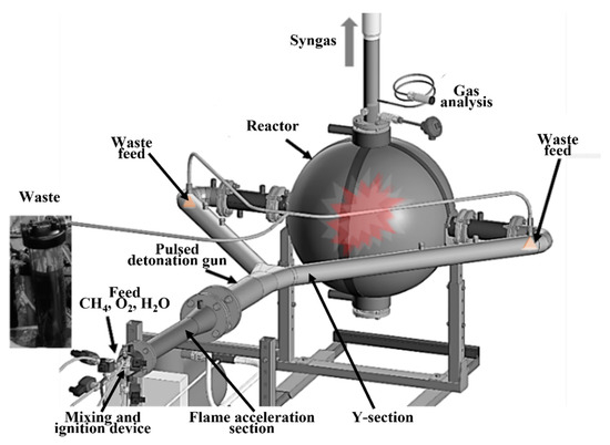
Figure 2.
Schematic of organic-waste gasifier with a pulsed detonation gun.
Figure 3 shows the calculated time histories of the mean temperature in a 100 L flow reactor at pulsed detonation gun operation with a frequency of f = 1 and 5 Hz without waste feed. The value of 5 Hz is taken as an extreme condition just to show a difference. Calculations were performed according to the procedure described in [20]. The mass of USS released to the flow reactor in each detonation pulse was ~10 g. Reactor walls were maintained at a constant temperature of Tw = 450 K. The sawtooth-like variation in the mean temperature is caused by the periodic release of shock waves and supersonic USS jets into the flow reactor with subsequent expansion of USS to a pressure of P = 0.1 MPa and its cooling on the reactor walls. During the operation of the pulsed detonation gun with a frequency of f = 1 and 5 Hz, the time-averaged mean temperature of the USS was 1200 K and 2200 K, respectively. Additionally, Figure 4 shows the influence of the reactor wall temperature on the calculated time histories of the mean USS temperature in the flow reactor during pulsed detonation gun operation at a frequency of 5 Hz without waste feed. A change in the temperature of the reactor wall from 450 to 800 K leads only to a slight increase in the time-averaged mean USS temperature: from 2200 to 2300 K. This means that the walls of the flow reactor can be cooled, and it is not necessary to use expensive heat-resistant materials for their manufacture.
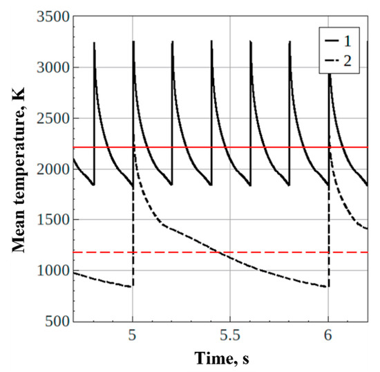
Figure 3.
Calculated time histories of mean temperature in the flow reactor at pulsed detonation gun operation with a frequency of = 5 (1) и 1 Hz (2) without waste feed: = 450 K, = 0.1 MPa.
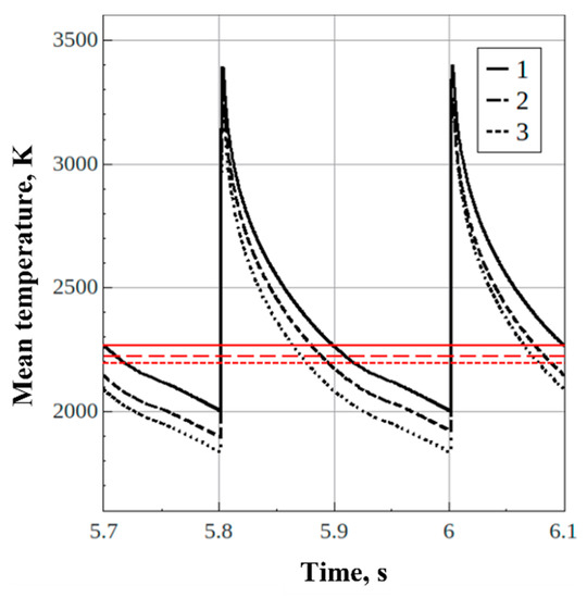
Figure 4.
Calculated time histories of mean temperature in the flow reactor at pulsed detonation gun operation with a frequency of = 5 Hz without waste feed ( = 0.1 MPa): = 800 K (1), 650 K (2) и 450 K (3).
2.2. Gasifier
The pulsed detonation gun is a water-cooled stainless-steel tube with an inner diameter of 50 mm and wall thickness of 2.5 mm. The tube contains three sections: a mixing and ignition device, a flame acceleration section 0.9 m long, and a Y-shaped end section (hereinafter referred to as the “Y-section”) with tube branching. Each of the two branches of the Y-section is a tube 50 mm in internal diameter and 1.4 m long.
The mixing and ignition device is equipped with a mixing head with supply manifolds for natural gas, oxygen, and low-temperature steam, as well as two standard spark plugs (VAZ, Russia) with ignition energies of ~100 mJ. Each manifold is equipped with a flame arrester (Donmet, KOG, Russia) controlled by solenoid valve (Rosma, Russia) and check valve (Donmet, KOK, Russia). Natural gas and oxygen are supplied to the pulsed detonation gun from the pressurized fuel and oxygen receivers, which communicate with natural gas cylinders (EM12-50x20-M, Monitoring-NPO, Russia) (volume 600 L) and liquid oxygen cryocylinder (DWP650-495-1.6, CIMC Sanctum Cryogenic Equipment & Co, China) (volume 495 L), respectively. Low-temperature steam is supplied to the gun to form an inert “plug” between hot detonation products of each previous operation cycle and fresh fuel mixture of each new cycle to prevent parasitic ignition. Steam is supplied from the industrial electric steam generator EPG-100 (Russia) through a heat-insulated line. The steam generator has a capacity of up to 50 kg/h with a maximum steam temperature of 150 °C. High voltage (30 kV) is supplied to the spark plugs from the standard automobile ignition module (VAZ, Russia).
The flame acceleration section is designed to ensure fast deflagration-to-detonation transition (DDT) and the formation of a steady detonation wave in natural gas–oxygen mixture. In this section, the apparent flame velocity increases from several meters per second to ~2.4 km/s. At the end of the flame acceleration section, a low-temperature steam supply manifold is installed, also equipped with a flame arrester controlled by solenoid and check valves. Low-temperature steam is supplied from the EPG-100 electric steam generator through a heat-insulated line to form a ternary “natural gas–oxygen–steam” mixture in the Y-section of the pulsed detonation gun.
The Y-section of the pulsed detonation gun is designed to split the detonation wave generated in the flame acceleration section into two steady-state detonation waves. These two detonation waves propagate in the branch tubes filled with the ternary natural gas–oxygen–steam mixture and enter the flow reactor synchronously. At the end of each branch tube, spray injectors connected with manifolds 6 mm in diameter and 3 m long are provided for continuous feed of liquid waste at a mass flow rate of up to 10 g/s from a 6 L tank. The tank is pressurized by nitrogen or air at the overpressure ranging from 0.1 to 0.4 MPa. In addition, at the end of each branch tube, it is possible to install screw feeders of crushed solid waste with the rotation speed controlled by a frequency converter. In periodic detonation waves, both liquid and solid wastes undergo fine aerodynamic fragmentation and enter the reactor together with supersonic jets of hot detonation products.
The flow reactor with a volume of 100 L is made of steel with a sectioned water-cooling jacket. The flow reactor withstands an accidental internal explosion with the maximum overpressure of ~1.4 MPa inherent in the explosion of methane–oxygen mixture. The inner surface of the flow reactor is designed so that no stagnant zones are formed, in which waste could accumulate. The flow reactor is equipped with four flanges. Two opposite horizontal flanges are used for connecting the branch tubes of the Y-section. The lower (technological) flange is designed for loading batches of solid waste, removing solid mineral residue, visual inspection, etc. The outlet tube is connected to the upper flange through a separator device aimed for removing gaseous gasification products (syngas). The separator device is fabricated in the form of a perforated tube 40 mm in diameter with 4 mm holes covered with a screen to prevent particles of liquid and solid waste from entering the outlet tube. Hot syngas flows from the reactor to a tubular cooler, where it is dried, quenched, and cooled to 40 °C. Next, the syngas enters the cyclone for fine separation of the condensed and gas phases. Water condensate and mineral residues are held in a reservoir in the lower part of the cyclone and periodically removed, while the flow of dry syngas branches: one (small) part of it enters the gas analysis system, and the other is directed to a diffusion burner equipped with a water-spray-assisted flame-extinguishing system. Note that burning the product syngas is only the intermediate solution. After the pulsed detonation gun technology is thoroughly tested, a part (about 20%) of the product syngas will replace natural gas for USS production, whereas the rest of the product syngas will be used for downstream needs, i.e., production of heat, electricity, chemicals, etc.
The gas analysis system consists of a sample preparation line with condensation of vapors, fine filters (standard automotive fuel filters) and three glass flasks with diesel oil connected in series. In flasks, the product syngas is bubbling through diesel oil, reaching a high degree of purification, and enters the sensors of the flow gas analyzer MRU VARIO SYNGAS PLUS (Germany). The gas analyzer records the volume fractions of H2, CO, CO2, CxHy, O2 and N2. The volume fraction of H2O in the syngas is estimated from the mass of the condensate. The measurement error of volume fractions is estimated at 5%. Data on the composition of the syngas are displayed on the screen and recorded in the memory unit of the gas analyzer.
The most important systems in the gasifier are safety system and control system based on relay TEMP-1M (Russia). They include sensors and actuators. During normal operation of the gasifier, flame arresters with fast-acting check valves on the natural gas, oxygen, and steam supply lines prevent the flame from flashing up the lines. A misfire or a failure of DDT in the pulsed detonation gun can result in a release of explosive mixture to the flow reactor with a danger of subsequent internal explosion. The danger of internal explosion is increased by several successive misfires or failures of DDT. To improve ignition reliability, two spark plugs are installed in the mixing and ignition device. In addition, a pressure sensor installed at the reactor inlet is used to monitor a misfire: if the overpressure is below a certain threshold value, the pulsed detonation gun is purged with low-temperature steam. To ensure the inherent safety of the operation process in case of DDT failure, the branch tubes of the Y-section are always filled only partly with the explosive mixture. When DDT fails, the flame front “covers” the entire charge of the explosive mixture before it enters the flow reactor. In addition, to monitor the failure of DDT, two pairs of ionization probes [22] installed in both branch tubes of the Y-section are used. Based on the readings of the probes, the instantaneous propagation velocities of detonation waves are determined. When DDT fails, the pulsed detonation gun is purged with low-temperature steam. To monitor the pressure and temperature in the flow reactor, a pressure sensor (Curant DI 1.6 MPa, Metronic, Russia) and thermocouple (Oven, Russia) installed in the outlet tube immediately after the separator device are used. Thermocouples are also used to monitor the coolant temperature in the water-cooling jackets of the pulsed detonation gun and flow reactor.
The operation of the gasifier includes three successive stages: starting mode, steady-state thermal mode and shutdown mode. In the starting mode, neither steam nor waste are fed to the gasifier, but changes in the thermal state of the gasifier and in the composition of the cooled dry detonation products are monitored. The start-up mode switches to a steady-state thermal mode when the temperature of the coolant in the cooling jackets of the pulsed detonation gun and flow reactor reaches a predetermined constant level (110–140 °C), and the composition of the cooled dry detonation products stops changing with time. Note, the time taken for the volume fractions of gas components to reach steady-state values is determined not only by the thermal state of the gasifier, but also by the response time of the sensors, the rate of purging the sampling line in the gas analyzer, and the rate of gas substitution in the analyzer volume. Considering all these factors, the time for the gasifier to reach a steady-state thermal mode is about 5 min. After the gasifier has reached a steady-state thermal mode, steam and waste can be additionally fed to it: in this case, the gas analyzer shows the composition of the product syngas. The feed of steam and waste leads to a new short-term transient operation, but now the thermal state of the gasifier does not change much. In the shutdown mode, the waste feed is first stopped, then the supply of natural gas, oxygen and steam is sequentially stopped.
The gasifier is placed in a 20-foot sea container and is equipped with all necessary inputs (electricity, oxygen, natural gas, water), a syngas utilization box with a diffusion gas burner and a flame extinguishing system, as well as communication lines for remote control of the operation process.
2.3. Materials
Four series of experiments were performed. In the first preliminary series, multiple experiments were performed aimed at controlling detonations in the pulsed detonation gun and testing all systems of the gasifier, including the safety system. In the second series, the chemical composition of the cooled dry detonation products of natural gas–oxygen mixture was determined. This series of experiments was performed without liquid/solid waste feed into the gasifier. The composition of natural gas is shown in Table 1. In the third and fourth series, experiments on liquid and solid organic wastes, namely, waste machine oil and wood (birch) sawdust, were performed, respectively. The proximate and ultimate analyses of birch wood and waste machine oil are shown in Table 2. At this stage of the study, all experiments were performed without diluting the natural gas–oxygen mixture with low-temperature steam at a frequency of detonation pulses f = 1 Hz, because the detonation products of natural gas–oxygen mixtures contain a significant amount of steam. For example, the equilibrium concentration of H2O in the detonation products of the stoichiometric methane–oxygen mixture expanded to 0.1 MPa is about 65%vol (see below). Each experimental run was repeated at least 3 times to collect the data on the reproducibility of results in terms of the average value and the run-to-run scatter of this value.

Table 1.
Composition of natural gas.

Table 2.
Proximate and ultimate analyses of birch wood and waste machine oil.
3. Results
3.1. Controlled Detonations in the Pulsed Detonation Gun
At an operation frequency of f = 1 Hz, the mass flow rate of the explosive mixture (and detonation products) through the pulsed detonation gun is ~10 g/s. During the fill process, the supply pressure of oxygen and natural gas, as well as their mass flow rates, are controlled. Based on the ratio of mass flow rates, the overall fuel-to-oxygen equivalence ratio Φ in the mixture is determined. The error in determining Φ is estimated at 5%. Upon completion of the fill process, the mixture is ignited. Mixture ignition is followed by flame acceleration and DDT, formation of a detonation wave and its bifurcation in the Y-section of the pulsed detonation gun. Detonation wave propagation in the pulsed detonation gun is controlled by eight ionization probes installed along the gun (Figure 5): two probes (1 and 2) at the end of the flame acceleration section, and three probes in each branch tube (3, 5, 7 and 4, 6, 8, respectively). It can be seen from Figure 5 that in both branch tubes, detonation waves propagate synchronously. Knowing the distance between the ionization probes and the time interval between the arrival of the detonation wave front on neighboring probes, one can determine the detonation velocity. Figure 6 shows the change in the detonation velocity along the length of the pulsed detonation gun. The vertical bars correspond to the cycle-to-cycle variability in the detonation velocity (±200 m/s). The horizontal dashed line corresponds to the Chapman–Jouguet (CJ) thermodynamic detonation velocity (~2400 m/s) at Φ = 1.0. The excess in the measured detonation velocity over this value in the initial section of the gun is caused by detonation overdrive during DDT. The decrease in the measured detonation velocity at the end of the gun is caused by the incomplete fill of the branch tubes with the explosive mixture and by diluting the explosive mixture with purge steam. In the gun segment from 500 to 1100 mm, the detonation velocity is seen to vary within the range of 2100–2600 m/s. The time taken for filling the volume of pulsed detonation gun of Figure 2 with a combustible mixture is estimated at ~0.4 s. The measured time taken for the DDT and detonation wave propagation along the pulsed detonation gun is about 2 ms, and the characteristic residence time of the major mass of detonation products in the gun is also few milliseconds. Thus, a major part of the operation cycle time is occupied by the fill process. After the detonation products release to the flow reactor, the supply valves of oxygen, natural gas, and steam are kept closed for some time (for about 0.6 s); thereafter, a new cycle starts.
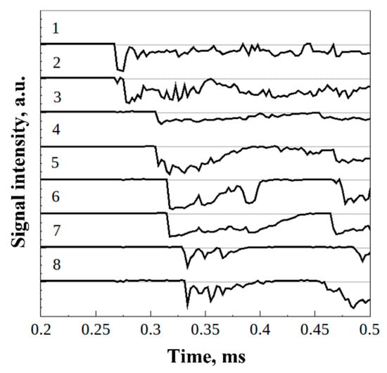
Figure 5.
Example of ionization probe readings in one of operation cycles.
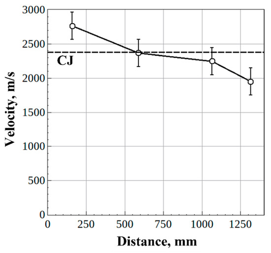
Figure 6.
Mean detonation velocity at the various measuring segments of the pulsed detonation gun in several operation cycles.
3.2. Experiments on Natural Gas Conversion
The first experiments were performed without waste feed into the gasifier. The objective of these experiments was to determine the chemical composition of the cooled dry detonation products of natural gas–oxygen mixtures with 0.9 ≤ Φ ≤ 1.8. In fact, in experiments with Φ > 1, autothermal high-temperature H2O/CO2-assisted conversion of natural gas occurred in the pulsed detonation gun, with steam and carbon dioxide generated as the oxidation products of a part of natural gas. In this case, the flow reactor of the gasifier played the role of a “cooler” used to “freeze” the composition of detonation products due to their rapid gun-to-volume expansion. This idea became the basis of our patent [23].
Figure 7 shows an example of primary records of changes in the composition of cooled dry detonation products with a stepwise variation of Φ from 0.91 to 1.4 in one experiment. In this experiment, the gasifier was preliminarily brought to a steady-state thermal mode. Changes in Φ affected the gun wall temperature insignificantly. As Φ changes, the volume fractions of H2, CO, CO2, and O2 also change (the volume fraction of CH4 is zero). Figure 8 shows the measured steady-state volume fractions of these substances at different values of Φ. At Φ < 1, in addition to H2O (not identified by gas analyzer) and CO2 (identified by gas analyzer), the cooled dry detonation products contain a significant amount of O2 (up to 15%vol d.b.). However, at Φ > 1, the volume fraction of O2 decreases to zero. In this case, the volume fraction of H2 gradually increases, the volume fraction of CO reaches a constant value of ~40%vol d.b., and the volume fraction of CO2 decreases. At Φ = 1.8, the cooled dry detonation products mainly contain H2 (~50%vol d.b.), CO (~40%vol d.b.) and CO2 (~10%vol d.b.). The maximum run-to-run scatter in the measured values of volume fractions of H2 and CO is ±4%. The H2/CO and CO/CO2 ratios in the product syngas are approximately 1.25 and 4, respectively.
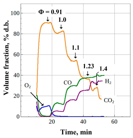
Figure 7.
Time history of the composition of cooled dry detonation products of CH4/O2 mixture at stepwise variation of Φ ( = 1 Hz, 0.1 MPa).
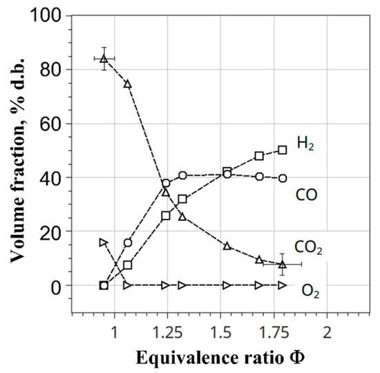
Figure 8.
Measured composition of cooled dry detonation products of CH4/O2 mixture vs. Φ ( = 1 Hz, 0.1 MPa). Measurement errors are shown only for the limiting values of Φ.
It is interesting to compare the measured volume fractions of H2, CO, CO2, and O2 with the “frozen” composition of detonation products of methane–oxygen mixtures rapidly expanded to P = 0.1 MPa in a flow reactor. For this purpose, thermodynamic calculations (P-T problem) were performed at temperatures of composition freezing ranging from 1400 to 2600 K, since this freezing temperature was unknown in advance. It turned out that the measured and calculated compositions of expanded dry detonation products agreed best with each other at a freezing temperature of 2200 K. Figure 9 compares the measured and calculated compositions at a temperature of 2200 K and a pressure of P = 0.1 MPa. In addition, Figure 10 shows the calculated composition of detonation products including steam as a function of Φ. The calculated volume fractions of H2O and CO2 at Φ = 1 are 65 and 30%, and at Φ → 2 they decrease to ~30 and ~5%, respectively. As the mean temperature in the flow reactor is considerably less than 2200 K (only ~1200 K, see Figure 3), the results of Figure 9 and Figure 10 indicate that natural gas conversion proceeds in the detonation waves while they propagate along the pulsed detonation gun, rather than in the flow reactor itself. It also follows from Figure 9 and Figure 10 that, in contrast to modern low-temperature technologies of steam and steam–carbon dioxide conversion of natural gas, the pulsed detonation gun technology provides complete (100%) natural gas conversion, and at Φ → 2, dry syngas mainly contains H2 and CO with the H2/CO ratio of approximately 1.4.
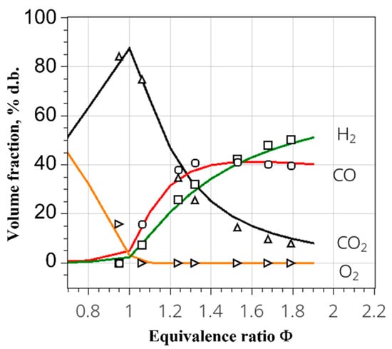
Figure 9.
Comparison of measured (symbols) and calculated (curves) volume fractions of cooled dry detonation products of CH4/O2 mixture. The calculation is made for the composition freezing temperature 2200 K.
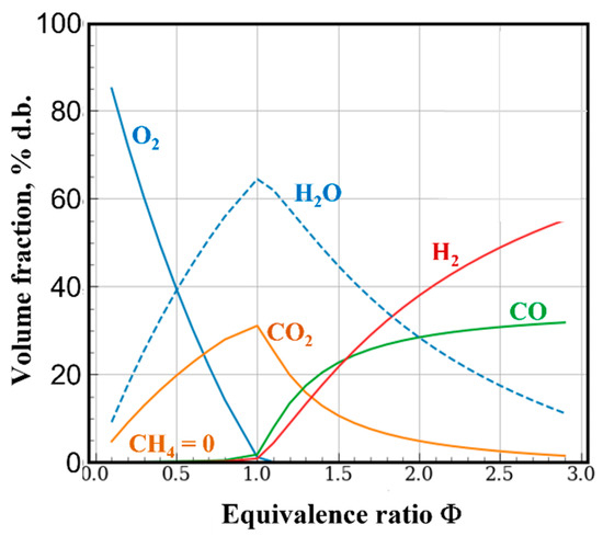
Figure 10.
Calculated compositions of detonation products of CH4/O2 mixtures with different values of Φ at the composition freezing temperature 2200 K ( = 1 Hz, = 0.1 MPa).
3.3. Gasification of Liquid and Solid Organic Wastes
Discussed below are the results of experiments performed separately with liquid and solid organic wastes, namely, waste machine oil and wood (birch) sawdust, respectively, when the pulsed detonation gun was operated at a frequency of f = 1 Hz on a natural gas–oxygen mixture with Φ = 1.1. This value of Φ was chosen because free oxygen was completely absent in the detonation products (see Figure 9 and Figure 10).
Liquid waste was continuously fed into the flow reactor using spray injectors installed at the end of each branch tube of the Y-section of the pulsed detonation gun. The mean diameter of liquid droplets in a free spray measured by the slide sampling method [24] was about 100 µm. The mass flow rate of liquid varied from G = 0 to 3 g/s. The duration of the experiment reached 10–15 min. The maximum overpressure in the flow reactor reached 0.25 MPa.
A batch of solid waste weighing 2 kg was loaded into a preheated flow reactor through the lower flange. The initial moisture content of sawdust was 25–30%wt. Sawdust particle sizes ranged from 1 to 9 mm. The duration of the experiment reached 15–20 min.
The gas temperature in the flow reactor, measured by a thermocouple installed in the outlet tube downstream of the separator device, reached 900 K in the experiments under consideration. This temperature was ~300 K lower than the time-averaged mean temperature of the USS obtained in calculations at f = 1 Hz (see Figure 3). It should be noted that the calculations were performed for the conditions without waste feed in the flow reactor and without considering the separator device with a large surface area, which could increase heat loss.
3.3.1. Liquid Waste
Figure 11 shows measured steady-state volume fractions of H2, CO, CO2 and CH4 in the product syngas versus the mass flow rate of liquid waste, G (O2 volume fraction is zero). The composition of the syngas at G = 0 corresponds to the composition of cooled dry detonation products of the natural gas–oxygen mixture with Φ = 1.1. Despite a relatively low time-averaged mean gasification temperature (~1200 K), the volume fractions of H2, CO, CO2, and CH4 in the product syngas at G > 0 differ from their values at G = 0. The volume fractions of H2, CO, and CH4 increased from 10, 20, and 0%vol d.b. at G = 0 to 30–35, 30–40, and 6–10%vol d.b., at G > 0, respectively, while the volume fraction of CO2 decreased from 70 to 20–30%vol d.b. The maximum run-to-run scatter in the measured values of volume fractions of H2 and CO is ±5%. Thus, the H2/CO and CO/CO2 ratios in the product syngas were approximately 0.8 and 2. The total volume fraction of combustible gases (H2, CO, and CH4) in the product syngas increased from 30%vol d.b. at G = 0 to 80%vol d.b. at G > 0. These changes are obviously caused by the gasification reactions.
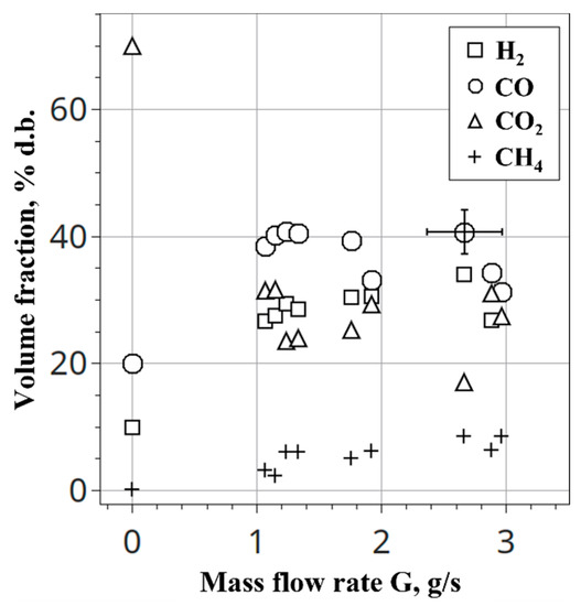
Figure 11.
Measured composition of cooled dry products of liquid waste gasification versus the mass flow rate of waste ( = 1 Hz, 0.1 MPa). Measurement errors are shown only for the near-limiting value of G.
3.3.2. Solid Waste
Contrary to experiments with liquid waste, experiments with solid waste were performed using a batch feed scheme. A batch of waste was loaded in the flow reactor and gasified over some period of time. In this case, both the temperature of the gases in the flow reactor and the composition of the product syngas reached steady-state levels starting from a certain point in time. After a certain period of gasifier operation, the composition of the product syngas began to change again, which indicated the completion of the gasification process due to the lack of feedstock. As an example, Figure 12 shows primary records of changes in the composition of cooled dry syngas during the experiment. Time point “0” in Figure 12 corresponds to the beginning of the release of the product syngas to gas analyzer. The volume fractions of H2, CO, CO2 and CH4 increased to steady-state values of 20, 40, 35, and 5%vol d.b., respectively. The maximum run-to-run scatter in the measured values of volume fractions of H2 and CO is ±5%. The H2/CO and CO/CO2 ratios in the product syngas were approximately 0.5 and 1.15. The total volume fraction of combustible gases in the product syngas (H2, CO, and CH4) increased to 65%vol d.b. Obviously, these changes were caused by the gasification reactions. Note that the composition of the product syngas was well reproduced from experiment to experiment.
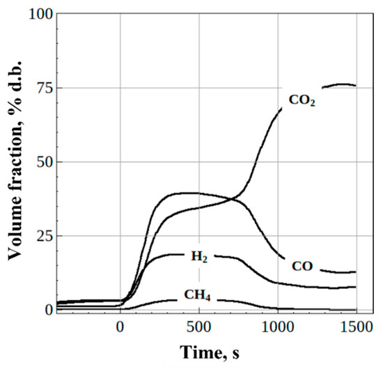
Figure 12.
Measured time histories of the cooled dry syngas composition obtained by gasification of solid organic waste (sawdust) at = 1 Hz and 0.1 MPa.
4. Discussion
Figure 13 compares the compositions of the syngas obtained in all experiments with natural gas conversion, as well as in experiments with the feed of liquid and solid organic wastes under the same conditions (f = 1 Hz, P ≈ 0.1 MPa). Comparison of syngas compositions is made in terms of the dependences of the steady-state values of H2, CO, and CH4 volume fractions on the CO2 volume fraction in the product syngas. With a decrease in the volume fraction of CO2 caused by the supply of natural gas, liquid or solid waste, the volume fractions of H2 and CO are seen to increase, with H2 tending to 60%vol d.b. and CO reaching a plateau at 40%vol d.b. It is interesting that the composition of the syngas in terms of H2 and CO volume fractions, which is produced in the gasifier at f = 1 Hz and P ≈ 0.1 MPa, looks almost independent of the type of organic feedstock—natural gas, liquid waste oil, or solid sawdust, despite natural gas conversion occurs in the detonation waves at very high temperatures for a relatively short time (several milliseconds), whereas liquid and solid wastes are gasified in the flow reactor at considerably lower temperatures but a considerably longer time (several seconds). The former is the reason that CH4 volume fraction in the product syngas of natural gas conversion is zero, and the latter is the reason that CH4 volume fraction in the product syngas of liquid/solid waste gasification is nonzero and reaches ~8%.
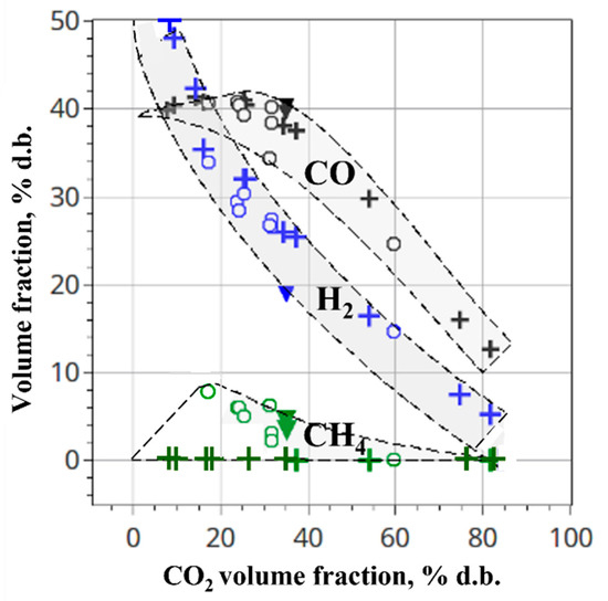
Figure 13.
Comparison of syngas compositions in all experiments with natural gas conversion, (crosses), and liquid (circles) and solid (triangles) waste gasification under the same conditions at = 1 Hz and 0.1 MPa. Black symbols correspond to CO, blue to H2, and green to CH4.
Very similar compositions of syngas were reported by other researchers using high-temperature techniques for organic waste gasification. Thus, the plasma torch with hybrid water/gas stabilization of arc was used in [9,10] for steam/CO2 gasification of pyrolysis oil, wood sawdust, and refuse-derived fuel at a mean process temperature of 1150–1350 K and pressure of 0.1 MPa, which is very close to the process mean temperature and pressure in the current experiments (~1200 K and 0.1 MPa). For pyrolysis oil, the volume fractions of H2, CO, and CH4 in the product syngas were 58, 33, and 4.9%, respectively, at CO2 volume fraction of 4% [10]. For wood sawdust, the volume fractions of H2, CO, and CH4 in the product syngas were 42–43, 44–49, and 1.3–1.7%, respectively, at CO2 volume fraction of 4.7–7.2% [9]. For refuse-derived fuel, containing 47%wt plastics, 24%wt wood and paper, 10%wt textiles, and 18%wt fines, the volume fractions of H2, CO and CH4 in the product syngas were 41–50, 44–41, and 5–3%, respectively, at CO2 volume fraction of 9.4–6.5% [10]. These results fit well the data of Figure 13.
Gasification of liquid and solid wastes occurs mainly due to the heterogeneous endothermic reactions of water gas, Boudouard, and hydrogasification [1,2]:
as well as gas-phase reactions of steam and dry reforming, and the water–gas shift reaction:
C + H2O = CO + H2; C + CO2 = 2CO; C + 2H2 = CH4
CnHm + nH2O = nCO + (n + 0.5m)H2;
CnHm + nCO2 = 2nCO + 0.5mH2; CO + H2O = CO2 + H2
The rates of these reactions are highly dependent on the temperature of the gasifying agent, and the degree of completion of these reactions depends on the residence times of condensed and gas phases in the flow reactor. At what temperature do reactions (1), (2) and other accompanying processes proceed, if one considers the sawtooth-like change in the mean temperature (see Figure 3) in a flow reactor? To answer this question, let us consider Figure 14, supplementing Figure 3. Figure 14 shows the calculated time histories of the maximum temperature Tmax in the flow reactor during steady-state operation of the pulsed detonation gun with a frequency of f = 1 and 5 Hz without waste feed. The red horizontal lines show the corresponding time-averaged mean temperatures of 1200 K and 2200 K. Let us first consider the curves for f = 1 Hz, that is, the frequency used in the experiments. During the first quarter of the cycle (~0.25 s), the maximum temperature is seen to be very high: 1500 ≤ Tmax ≤ 2300 K. Then, in the second quarter of the cycle, it decreases to 1200 ≤ Tmax ≤ 1500 K and in the second half of the cycle it drops below 1200 K. If the operation frequency of the pulsed detonation gun rises to f = 5 Hz, then Tmax > 2000 K throughout the entire operation cycle, and the time-averaged mean temperature is 2200 K.
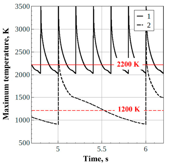
Figure 14.
Calculated time histories of the maximum mean temperature in the flow reactor at pulsed detonation gun operation with frequencies of = 1 and 5 Hz without feed of waste ( = 450 K, = 0.1 MPa). Horizontal lines correspond to the time-averaged mean temperature values in the flow reactor.
It is well known from the equilibrium calculations of organic waste gasification [25] that at temperatures ~900 K, carbon and oxygen exist as CO2, tar and char, i.e., tar and char conversion is low; at temperatures above ~1200 K, in the presence of carbon, CO2 breaks down to CO and available oxygen mostly reacts with carbon to form CO and CO2 rather than with H2 to form water; and at temperatures above ~1800 K tar and char are completely transformed to syngas composed mainly of H2 and CO. According to Table 1 and Table 2 natural gas and waste oil contain comparable amounts of carbon (~95 and ~85%wt, respectively) in their composition, whereas wood sawdust contains only ~49%wt carbon and ~45%wt oxygen. Therefore, it is not that surprising that syngas compositions for natural gas and waste oil in Figure 13 are close to each other in terms of H2 and CO contents. As for wood sawdust, at high temperatures (above ~1200 K) the bound oxygen available in wood mostly reacts with carbon to form CO. In view of it, the amount of CO in the gasification products of sawdust is as high, as that in the gasification products of natural gas and waste oil.
It is worth noting that no condensed-phase by-products such as tar and char were detected in the gasification experiments under discussion. Additionally, there were no mineral residues. On the one hand, it is explained by the feedstocks used (natural gas, waste machine oil, and wood sawdust) containing nearly no ash. On the other hand, it is explained by high gasification temperature (well above 1200 K) and relatively long residence time (up to 15 s [20]) of feedstocks in the gasifier.
It can be assumed that, at f = 1 Hz, reactions (1) and (2) mainly proceed at a high local instantaneous temperature, for example, in the first quarter of the operation cycle, while during the rest of the cycle they proceed much more slowly. Since the median residence time of waste particles with a size of 0.1 or 1 mm in a 100 L spherical flow reactor is only several seconds [20], then at a detonation pulse frequency f = 1 Hz, only a quarter of the residence time (~0.25 s) is allotted for the rapid progress of gasification reactions. Moreover, since far from all particles reach the high-temperature zones during this time, it can be expected that the total conversion of carbon contained in the waste is relatively low under these conditions. On the contrary, at f = 5 Hz, the rapid course of reactions (1) and (2) takes the entire cycle time, and a very high degree of carbon conversion can be expected.
Thus, the pulsed detonation gun technology developed and applied herein has several attractive features. First, it allows the production of gasification steam with a very high temperature (above 2000 °C) at atmospheric pressure, which is impossible with a boiler. When using such a steam for waste gasification, it becomes possible to obtain full carbon conversion to syngas containing only H2 and CO (with no by-products such as tar and char and therefore no expensive gas aftertreatment). Second, such a steam is obtained by shock compression without a need for heat transfer surfaces (accompanying losses are absent). Third, detonation steam, in addition to its thermal energy, possesses huge kinetic energy which can be used for creating intense vortical flows promoting gasification reactions in gasifiers, as well as for in situ feedstock fragmentation, separation of products with different densities, etc. Fourth, due to the intense vortical motion in a gasifier resembling the flow in a piston engine, the gasifier walls can be fabricated from cheap regular construction materials and can be water-cooled without much effect on the net rate of the gasification process (no need for applying expensive heat-resistant materials and/or refractory linings for gasifier walls). Fifth, feedstock parameters such as particle size distribution, moisture, composition, etc., seem to be much less significant than for other gasification technologies because strong detonation-induced shock waves and dense supersonic USS jets facilitate secondary fragmentation of particles and fast involvement of feedstock moisture in the gasification process. This means that the technology could be equally applicable to gasification of municipal waste fragmentation and gasification, lignin, sewage and industrial sludge gasification, coal and coal sludge residue gasification, gasification of toxic and nontoxic liquid (liquified) wastes, and toxic (e.g., medical) waste fragmentation and gasification. Sixth, the pulsed detonation gun technology promises to be cost effective, as only a small part (ideally, about 10%, see below) of produced syngas could be used for generating USS via pulsed detonations in mixtures with oxygen. The issues that still need to be addressed before technology implementation on an industrial scale are the noise and vibrations, as well as mechanical strength and wear of a pulsed detonation gun and gasifier materials.
5. Mass and Energy Balances
This section presents the ideal mass and energy balances for the pulsed detonation gun technology of organic waste gasification. For the sake of definiteness, we consider a pulsed detonation gun operating on the stoichiometric mixture of syngas (H2/CO = 1) with O2 diluted by 40%vol H2O, and dry wood sawdust as a feedstock (see Figure 1). According to [6], due to the detonation of such a mixture in the pulsed detonation tube, high-temperature (~2300 K) gaseous detonation products, containing mainly H2O and CO2 with the H2O/CO2 ratio of 3/1, form according to overall reaction:
CO + H2 + O2 + 2H2O = CO2 + 3H2O
Table 3 shows the literature data on the standard heats of formation of relevant substances and latent heat of water vaporization. The heat of reaction (3) is equal to
∆H = −393.52 – 3 × 241.82 + 110.53 + 2 × 241.82 = −524.81 MJ/kmol

Table 3.
Heats of formation of substances and latent heat of water vaporization.
These gaseous detonation products are further used as a gasifying agent for atmospheric-pressure gasification of biomass in a flow reactor. Full gasification of biomass with the formation of syngas CO + H2 with H2/CO = 1 is assumed to occur in the flow reactor. A part of generated syngas is compressed and directed back to the pulsed detonation tube, whereas the rest of generated syngas goes to an external syngas user. The task is to determine a part of syngas used for ones’ own needs and a part directed to the external user with due regard for energy requirements for oxygen and steam production, and syngas compression before entering the pulsed detonation tube.
Let us assume that the thermal energy of detonation products is completely recuperated by the cooling system to the energy of low-temperature steam entering the pulsed detonation tube as a diluent, i.e., irreversible losses are absent. Additionally, let us take into account that (1) the physical energy required for production of O2 is 4 MJ/kg [26], which is 12 MJ/kg with regard for production efficiency (33%), (2) the energy requirement for syngas compression from 0.1 to 0.5 MPa (before entering the pulsed detonation tube) is 3 MJ/kg, which is 9 MJ/kg with regard for compression efficiency (33%), and (3) the heat of formation of dry wood sawdust is ~5.43 MJ/kg [27]. Let us consider the process with volumetric flow rates of CO and H2 equal to 1 kmol/h. The results of calculations of mass and energy balances in these conditions are presented in Table 4.

Table 4.
Mass and energy balances (without losses) for dry sawdust.
In summary, for converting 1 ton of dry sawdust one ideally needs 145 kg syngas, 155 kg O2, and 175 kg water. As a result of full gasification, one obtains 1000 + 145 + 155 + 175 = 1475 kg syngas, a part of which (145 kg, i.e., ~10%) is used for gasification of the next 1 ton of sawdust. The energy gain defined as the ratio of the total syngas energy after flow reactor (6430 MJ/h) to the energy spent in its production (1389 MJ/h) is 6430/1389 = 4.6.
6. Conclusions
In this work, the technology of a pulsed detonation gun for gasification of organic wastes with ultra-superheated steam has been experimentally demonstrated for the first time. Experiments were performed on natural gas conversion as well as on the gasification of liquid (waste machine oil) and solid (sawdust) waste by detonation products of natural gas–oxygen mixture at a frequency of detonation pulses f = 1 Hz, which provided a time-averaged mean temperature of detonation products in a 100 L flow reactor at a level of 1200 K and the average absolute pressure in the flow reactor at a level of 0.1 MPa. The following main results are obtained:
- (1)
- Unlike modern low-temperature technologies for steam and steam–carbon dioxide conversion of natural gas, the technology of a pulsed detonation gun can provide complete (100%) natural gas conversion into dry syngas mainly containing H2 and CO, with a ratio of H2/CO ≈ 1.25 and CO/CO2 ≈ 4.
- (2)
- Syngas produced by gasification of liquid and solid organic wastes contains 80 and 65%vol d.b. of combustible gases (H2, CO, and CH4) in the product syngas, respectively. The ratios of H2/CO and CO/CO2 in the syngas obtained from liquid and solid wastes are 0.8 and 2 (liquid waste) and 0.5 and 1.15 (solid waste), respectively.
- (3)
- Comparison of all experiments on natural gas conversion as well as experiments on gasification of liquid and solid organic wastes under the same conditions (f = 1 Hz, P ≈ 0.1 MPa) shows that the composition of the product syngas in terms of H2 and CO almost does not depend on the type of used organic feedstock.
- (4)
- Based on multidimensional gas–dynamic calculations of the operation process in the gasifier, it is concluded that at f = 1 Hz, gasification reactions mainly proceed in the first quarter of the operation cycle at a high local instantaneous temperature, whereas during the rest of the operation cycle they proceeded much more slowly. Under these conditions, due to the short residence time of liquid and solid waste particles in the flow reactor and the fact that not all particles enter the high-temperature zones, the overall conversion of carbon contained in the waste should be expectedly low.
- (5)
- On the contrary, at f = 5 Hz, the entire cycle time is assigned to the fast gasification reactions, and a very high carbon conversion can be expected.
- (6)
- The estimated ideal energy gain defined as the ratio of the total energy of product syngas to the energy spent to its production from dry wood sawdust is about 4.6, i.e., the pulsed detonation technology of biomass gasification is economically very attractive.
Author Contributions
S.M.F.: Conceptualization; methodology, writing original draft and editing; funding acquisition; project administration; V.A.S.: investigation; I.A.S.: investigation; A.S.S.: investigation; I.O.S.: investigation; V.S.A.: investigation; K.A.A.: investigation; F.S.F.: investigation. All authors have read and agreed to the published version of the manuscript.
Funding
This research received no external funding.
Institutional Review Board Statement
Not applicable.
Informed Consent Statement
Not applicable.
Data Availability Statement
The data presented in this study are available on request from the corresponding author.
Conflicts of Interest
The authors declare no conflict of interest.
References
- Basu, P. Biomass Gasification and Pyrolysis; Practical Design: Burlington, VT, USA, 2010. [Google Scholar]
- Bain, R.L.; Broer, K. Gasification, 1st ed.; John Wiley & Sons: Hoboken, NJ, USA, 2011. [Google Scholar]
- Chen, Z.; Zhang, X.; Gao, L.; Li, S. Thermal analysis of supercritical water gasification of coal for power generation with partial heat recovery. Appl. Therm. Eng. 2017, 111, 1287–1295. [Google Scholar] [CrossRef]
- Kazimierowicz, J.; Zieliński, M.; Dębowski, M. Influence of the Heating Method on the Efficiency of Biomethane Production from Expired Food Products. Fermentation 2021, 7, 12. [Google Scholar] [CrossRef]
- Siwal, S.S.; Zhang, Q.; Sun, C.; Thakur, S.; Gupta, V.K.; Thakur, V.K. Energy production from steam gasification processes and parameters that contemplate in biomass gasifier—A review. Bioresour. Technol. 2020, 297, 122481. [Google Scholar] [CrossRef] [PubMed]
- Frolov, S.M. Organic waste gasification: A selective review. Fuels 2021, 2, 556–650. [Google Scholar] [CrossRef]
- Frolov, S.M. Gasification of organic wastes by ultra-superheated steam and carbon dioxide. Combust. Explos. 2021, 14, 74–97. [Google Scholar] [CrossRef]
- Munir, M.T.; Mardon, I.; Al-Zuhair, S.; Shawabkeh, A.; Saqib, N.U. Plasma gasification of municipal solid waste for waste-to-value processing. Renew. Sustain. Energy Rev. 2019, 116, 109461. [Google Scholar] [CrossRef]
- Hrabovsky, M. Plasma Aided Gasification of Biomass, Organic Waste and Plastics. In Proceedings of the 30th ICPIG, Belfast, UK, 28 August–2 September 2011. [Google Scholar]
- Hrabovsky, M.; Hlina, M.; Kopecky, V.; Maslani, A.; Zivny, O.; Krenek, P.; Hurba, O. Steam plasma treatment of organic substances for hydrogen and syngas production. Plasma Chem. Plasma Process. 2017, 37, 739–762. [Google Scholar] [CrossRef]
- Vecten, S.; Wilkinson, M.; Bimbo, N.; Dawson, R.; Herbert, B.M.J. Hydrogen-rich syngas production from biomass in a steam microwave-induced plasma gasification reactor. Bioresour. Technol. 2021, 337, 125324. [Google Scholar] [CrossRef] [PubMed]
- Frolov, S.M.; Smetanyuk, V.A.; Avdeev, K.A.; Nabatnikov, S.A. Method for Obtaining Highly Overheated Steam and Detonation Steam Generator Device (Options). Patent of Russian Federation No. 2686138, 24 April 2019. [Google Scholar]
- Pierce, T.H.; Afify, E.M.; Zickefoose, R.T. Detonation-Induced Coal Gasification; Final Report (No. DOE/ET/10451-T1); North Carolina State University, Department of Mechanical and Aerospace Engineering: Raleigh, NC, USA, 1979. [Google Scholar]
- Pierce, T.H. Detonation-Induced Coal Gasification. Int. J. Energ. Res. 1987, 11, 203–231. [Google Scholar] [CrossRef]
- Hunter, L.G. Pulse Detonation Device for Coal Gasification. U.S. Patent 5,672,184, 30 August 1997. [Google Scholar]
- Mei, D.; Zhou, J.; Biney, P.O.; Huque, Z. Slag Characterization and Removal Using Pulse Detonation Technology during Coal Gasification; TR No. DE-FG22-95MT95010-10; Federal Energy Technology Center (FETC): Morgantown, WV, USA; Pittsburgh, PA, USA, 1998.
- Frolov, S.M.; Smetanyuk, V.A.; Nabatnikov, S.A. Method of Gasification of Coal in a Highly Overheated Water Vapor and Device for Its Implementation. Patent of Russian Federation No. 2683751, 1 April 2019. [Google Scholar]
- Frolov, S.M.; Nabatnikov, S.A.; Diesperov, K.V.; Achildiev, E.R. Method for Decontamination of a Fly Ash Formed during Burning of Wastes and a Device for Its Implementation. Patent of Russian Federation No. 2739241, 22 December 2020. [Google Scholar]
- Frolov, S.M.; Smetanyuk, V.A.; Shamshin, I.O.; Koval’, A.S.; Frolov, F.S.; Nabatnikov, S.A. Generation of highly superheated steam by pulsed detonation of the ternary gas “propane–oxygen–steam” mixture. Combust. Explos. 2019, 12, 95–103. [Google Scholar] [CrossRef]
- Frolov, S.M.; Smetanyuk, V.A.; Sergeev, S.S. Reactor for waste gasification with highly superheated steam. Dokl. Phys. Chem. 2020, 495, 191–195. [Google Scholar] [CrossRef]
- Frolov, S.M.; Smetanyuk, V.A.; Shamshin, I.O.; Sadykov, I.A.; Koval’, A.S.; Frolov, F.S. Production of highly superheated steam by cyclic detonations of propane and methane-steam mixtures with oxygen for waste gasification. Appl. Therm. Eng. 2021, 183, 116195. [Google Scholar] [CrossRef]
- Frolov, S.M.; Aksenov, V.S.; Dubrovskii, A.V.; Zangiev, A.E.; Ivanov, V.S.; Medvedev, S.N.; Shamshin, I.O. Chemiionization and acoustic diagnostics of the process in continuous- and pulse-detonation combustors. Dokl. Phys. Chem. 2015, 465, 273–278. [Google Scholar] [CrossRef]
- Frolov, S.M.; Avdeev, K.A.; Nabatnikov, S.A.; Shulakov, K.D. Pulse-Detonation Method for Producing Alkenes and Alkines and a Device for Its Implementation. Patent of Russian Federation No. 2744454, 9 March 2021. Priority Dated 18 December 2019. [Google Scholar]
- Frolov, S.M.; Basevich, V.Y.; Aksenov, V.S.; Polikhov, S.A. Optimization study of spray detonation initiation by electric discharge. Shock Waves 2005, 14, 175–186. [Google Scholar] [CrossRef]
- Ferreira, S.; Monteiro, E.; Brito, P.; Vilarinho, C. A Holistic review on biomass gasification modified equilibrium models. Energies 2019, 12, 160. [Google Scholar] [CrossRef]
- Patzek, T.W.; Croft, G.D. Potential for coal-to-liquids conversion in the United States—Fischer–Tropsch synthesis. Nat. Resour. Res. 2009, 18, 181–191. [Google Scholar] [CrossRef][Green Version]
- Burnham, A.K. Estimating the Heat of Formation of Foodstuffs and Biomass; Technical Report UCRL-TR-464095; Lawrence Livermore National Laboratory: Livermore, CA, USA, 2010.
Publisher’s Note: MDPI stays neutral with regard to jurisdictional claims in published maps and institutional affiliations. |
© 2022 by the authors. Licensee MDPI, Basel, Switzerland. This article is an open access article distributed under the terms and conditions of the Creative Commons Attribution (CC BY) license (https://creativecommons.org/licenses/by/4.0/).