Abstract
The paper analyses operating and developing technologies for hydrogen implementation, transition, and storage at operating thermal power plants (TPPs) to make recommendations for realization of perspective projects for evaluation of the use of hydrogen as a fuel. Over the medium-term horizon of the next decade, it is suggested that using the technology of burning a mixture of hydrogen and natural gas in gas turbines and gas-and-oil-fired boilers in volume fractions of 20% and 80%, respectively, be implemented at operating gas fired TPPs. We consider the construction of the liquefied hydrogen and natural gas storage warehouses for the required calculated quantities of the gas mixture as a reserve energy fuel for operating the TPPs. We consider the possibility of the reserve liquid fuel system being replaced by the technology involving storage of liquefied hydrogen in combination with natural gas. An economic assessment of the storing cost of reserve fuel on the TPP site is given. The paper suggests that the methane-hydrogen mixture be supplied to the TPP site by two independent gas pipelines for the possibility of using the mixture as the main fuel and to exclude fuel storage at the plant.
1. Introduction
Over the past two decades, there has been rapid development and implementation of the global decarbonization policy. This direction was set by the United Nations (UN), which held a conference on the environment and development in Rio de Janeiro in 1992 [1]. In order to implement the concept of decarbonization and control the transition of the countries to adopting this policy, conferences on environmental protection and decarbonization began to be held periodically, such as UN Framework Convention on Climate Change [2], where the Kyoto Protocol for the UN Framework Convention on Climate Change [3] and the Paris Agreement [4] were signed.
The most active participants in the campaign to reduce the carbon footprint are the countries of the European Union (EU). In 2020, European countries announced the decarbonization program “A European Green Deal” [5]. The document established an interim goal to reduce harmful emissions into the atmosphere by 2030 (by at least 55% compared to 1990 levels, instead of the previously planned 40%).
Within the framework of the EU strategy on energy system integration [6], which considers forming links between EU sectors for various energy carriers (electricity, heat, fuel, cold), plans are underway to include hydrogen in the list of the above energy carriers. At the same time as the EU hydrogen strategy in 2020, The European Clean Hydrogen Alliance was created as part of a new industrial strategy for Europe. The Alliance aims for the ambitious adoption of hydrogen technologies by 2030, combining the production of renewable and low-carbon hydrogen, hydrogen demand in industry, mobility, other sectors, as well as the hydrogen transmission and distribution. The EU wants to strengthen its global leadership in this area through the Alliance to support the EU’s commitment to achieve carbon neutrality by 2050 [7].
The policy of the Russian Government correlates with the global desire for decarbonization. To reduce the thermal impact on the environment, the government issued the Federal Law “On Limiting Greenhouse Gas Emissions”. The law assumes ensuring sustainable and balanced development of the economy of Russia while reducing greenhouse emissions [8]. The Government plans to achieve a balance between anthropogenic greenhouse gas emissions and their absorption by no later than 2060 [9].
In the context of the influence of global trends in the transition to a low-carbon economy on the situation regarding the energy sectors globally, including Russia [10], comprehensive development of energy infrastructure and the introduction of promising energy resources, and their processing to diversify energy exports is required. Hydrogen production shall become one of the most dynamically developing areas of energy resources processing.
Several state strategic planning documents aimed at achieving priority goals [11,12,13,14] outline the Russian hydrogen policy.
The strategic development of hydrogen energy in Russia will achieve the realization of the national potential in the field of production, export, use of hydrogen and industrial products for hydrogen energy; it will attain a global leading role in hydrogen production and export, ensuring the competitiveness of the country’s economy in the context of the global energy transition [14].
One of the carbon-neutral economy transition directions is the transfer conventional energy using organic fuel to hydrogen combustion. According to the hydrogen concept of Russia, one of the key factors contributing to the global introduction of hydrogen energy will be the development of technology for the implementation of hydrogen energy carriers in various sectors of the economy (including electric power), as well as the expansion of the usage of fuel cells, gas turbines and other hydrogen power units.
This method of hydrogen implementation has a fairly high cost of energy production, due to the higher cost of one ton of conventional fuel in the hydrogen equivalent. However, due to the presence of a developed infrastructure for operating fossil fuelled thermal power plants (TPPs), this method can be the main one for the transitional period based on the cost-effective conversion to hydrogen fuel for the main equipment, such as boilers and gas turbines [15].
The Russian energy sector’s peculiarity is the fact that the country has implemented a centralized heat supply based on heat and electricity cogeneration. According to the statistics of the Ministry of Energy of Russia, most of the thermal energy in Russia continues to be produced at TPPs (see Figure 1). The energy sector generated 5326 million GJ of thermal power in 2019, of which 2643 million GJ (up to 49.6%) were generated at operating TPPs. In total, Russia had 595 TPPs with a capacity of 500 kW and above operating in 2019. The number of TPPs has increased by 90 units since 2015. In such conditions, it seems impossible to stop heat and electricity generation at the operating TPPs and start the construction of new hydrogen operating energy facilities [16].
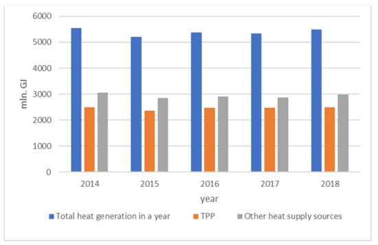
Figure 1.
Dynamics of heat energy supply by heat sources according to the data of the Ministry of Energy of the Russian Federation [16].
According to the Strategy of Socio-Economic Development of Russian Federation to achieve a low level of greenhouse gas emissions by 2050 [9], its intermediate stage is the creation of measures to reduce greenhouse gas emissions up to 70% by 2030 (relative to the 1990 level). The construction of new generating capacities operating on hydrogen will not achieve the goal by the specified deadline, and it will also require large capital investments. It is necessary to ensure the maximum involvement of the operating TPP equipment for hydrogen operation while maintaining heat transfer to consumers.
Integrating solutions for the production, transportation, storage, and implementation of hydrogen at operating TPPs of the Russian Federation will allow the achievement of a comprehensive solution to both the scientific problem and the practical implementation of the existing industrial task facing the energy sector in Russia.
The purpose of this paper is to develop recommendations for the existing and developing technologies for the usage, transportation, and storage of hydrogen at operating TPPs in Russia soon to achieve intermediate decarbonization goals.
2. Materials and Methods
The authors have developed a methodology for determining optimal solutions for technology integration of the usage, transition, and storage of hydrogen, applicable to the operating TPPs, presented in the form of a flowchart (see Figure 2). The methodology includes an analysis of global and Russian regulatory documents, scientific publications containing the results of research on the subject in peer-reviewed Russian and foreign scientific publications indexed in the Web of Science Core Collection and Scopus databases, as well as by margin analysis methods.
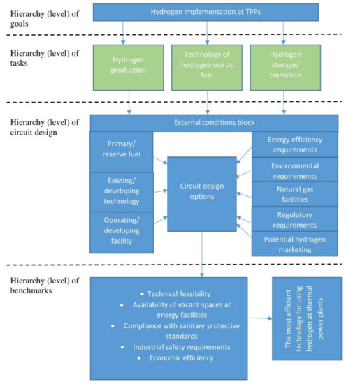
Figure 2.
Flowchart of the algorithm for determining optimal solutions for technology integration of the usage, transportation, and storage of hydrogen, applicably to the operating TPPs.
This methodology has been tested in this paper in relation to the operating TPPs of the Russian Federation.
3. Results and Discussion
The analysis of scientific literature indicates the possibility of obtaining hydrogen from the synthesis of the gas [17,18] generated in methane steam conversion units, or in coal [19,20], or in solid waste gasification plants [21,22,23], as well as by electrolysis units [24,25]. This thesis correlates with one of the provisions of the hydrogen strategy of Russia. The provision states: “Currently the most cost-effective way to produce hydrogen with a low carbon footprint is its centralized production based on technologies of steam conversion of methane and coal gasification with carbon dioxide capture, as well as method of water electrolysis based on electricity from nuclear power plants and hydroelectric power plants” [14]. In Russia, the prospects of hydrogen production at nuclear power plants based on off-peak generation are mainly considered [26,27,28,29]. In addition, there are studies based on the use of thermochemical processes that require a direct coupling of a chemical plant to a nuclear reactor [30] or generally on high-temperature gas cooled reactors, even in the connection with steam methane reformation [31,32,33,34]. Recently, studies have begun to appear integrating hydrogen production plants into the technological scheme of thermal power plants [19,20,35,36,37]. Hydrogen production by these methods is possible both at the TPP and off-site. Nevertheless, the analysis of hydrogen production technologies at TPPs is not considered in this paper.
Russia has accumulated some technological experience in the transport and storage of hydrogen. It is used mainly as a semi-product in chemical and oiling spheres (ammonia and methanol production, oil refining, etc.), but not as an energy carrier.
Nevertheless, at some power plants, hydrogen performs a cooling function for turbine generators, and therefore Russia has operating experience in the usage, storage, and transportation of hydrogen at energy facilities. Modernization of operating plants to hydrogen requires consideration of the features of the large-scaled use and storage of hydrogen as well as hydrogen delivery to power facilities.
Currently, there are the following promising technological options available for hydrogen implementation as a fuel applicable to modern technologies used in power generation at TPPs:
- The usage of hydrogen-containing fuel for gas turbine units (GTU), as well as steam and hot water boilers of various capacities.
- The usage of hydrogen to improve the efficiency of TPPs by means of hydrogen-oxygen steam generators and fuel cells.
3.1. The Usage of Hydrogen-Containing Fuel for Gas Turbine Units at Operating TPPs
In order to use hydrogen as a fuel in gas turbine units, it is important to determine the possibility of burning hydrogen-containing mixtures in “conventional” combustion chambers designed for natural gas. A methane-hydrogen mixture (MHM) is a mixture of natural gas with hydrogen (up to 20–40%). Hydrogen-containing gas (HCG) is a gas mixture containing hydrogen, for example, such gas can be coke oven gas, synthesis gas, etc.
Gases with the same Wobbe value at the same discharge pressure can be used interchangeably without replacing the burner or the nozzle. These values are lower for hydrogen-containing gas than for natural gas because of the characteristics of hydrogen (see Table 1).

Table 1.
Characteristics of natural gas, methane and hydrogen [38].
The volumetric heat of combustion of hydrogen is 3.4 times less than that of natural gas; the density is 8.3 times less; the mass heat of combustion is 2.4 times higher, and at the same time the Wobbe value of hydrogen is only 18% lower than that of natural gas. As the volumetric heat of combustion of hydrogen is significantly lower, the flow section of gas pipelines and the equipment in the fuel gas treatment system (such as filters, shut-off valves, heat exchangers) shall be increased relatively to the flow section of the natural gas pipeline during the combustion of the MHM.
For each gas turbine unit, there is an acceptable range of changes in the heat of combustion and the Wobbe value of fuel gas. Mixing hydrogen with natural gas increases the mass heat of combustion of the fuel gas. For example, with the maximum value of the mass heat of combustion of a Siemens SGT5-2000E gas turbine engine of 52.5 MJ/kg, the maximum permissible volume concentration of hydrogen in the fuel gas will be 0.27. When hydrogen is mixed with natural gas, the Wobbe value of the fuel gas will decrease, as the values of the volume Wobbe number of hydrogen are lower than that of natural gas (see Table 1). At the same time, for the SGT5-2000E GTU, the volume number of the Wobbe MHM is not a limiting factor. The limiting factor for it is the value of the maximum mass heat of combustion of the MHM [38,39].
According to the world’s leading gas turbine manufacturers (such as, Siemens, General Electric, Ansaldo energia, Mitsubishi Power, etc.) [40,41,42,43,44], existing gas turbines are capable of operating with a high percentage of hydrogen in the fuel, while the specific unit capabilities depend on the model of the gas turbine and the type of combustion system, as well as turbine engine operating conditions.
Hydrogen combustion in gas turbines has its own characteristics:
- The flame temperature for hydrogen under adiabatic and stoichiometric conditions is almost 300 °C higher than for methane.
- The speed of the laminar flame of hydrogen is more than three times the speed of methane.
- The delay time of the spontaneous ignition of hydrogen is more than three times less than that of methane for a flame temperature of 1600 °C.
Due to these characteristics, hydrogen is a highly efficient fuel. To control the flame while maintaining the integrity of the combustion system and achieve the desired level of emissions is a difficult task for research and development teams. To increase the hydrogen content in the fuel, changes in the equipment and control system are required to allow the equipment to operate safely, meet NOx emission limits and control various fuel compositions. Nevertheless, according to most manufacturers, increasing the volume concentration of hydrogen to 25–30% in the mixture will not require significant changes to the burners and the combustion chamber. Some experimental turbines can run on a mixture of natural gas and hydrogen with a volume fraction of hydrogen up to 50%. Work is underway to increase the proportion of hydrogen to 100%.
Major Russian manufacturers of gas turbines (such as Power Machines JSC, United Engine Corporation JSC) [45,46] also report interest in projects for the transfer of units to operate on hydrogen fuel. Currently, various research and development works are being carried out in the Russian Federation to adapt GTU to operate on methane-hydrogen mixtures. Specialized design bureaus are being created to develop, for example, a combustion chamber for a promising gas turbine unit with a capacity of 65 MW, in which a methane-hydrogen mixture will be used as fuel.
While developing the combustion chamber, specialists set themselves the following tasks:
- Optimization of the combustion chamber design.
- Determination of the most effective composition of the fuel mixture.
- Solving the problem of acoustic pulsations that occur during the combustion of hydrogen fuel.
- Developing measures to minimize emissions of nitrogen oxides NOx.
According to preliminary estimates, a Russian-made GTU with a capacity of 65 MW and 170 MW will be able to operate on methane-hydrogen fuel with a hydrogen fraction of up to 20–30% by volume without structural changes in the combustion chambers. The only changes required are in control algorithms and external fuel supply systems.
Hence, from the point of view of existing technologies, it is theoretically possible to convert existing gas turbines of Russian thermal power plants to burning hydrogen in a volume fraction of 20 to 30% in a mixture with natural gas.
Further proportional increase of hydrogen in the mixture will require solving several problems related to:
- The reactivity of hydrogen by upgrading the combustion chamber (one of the possible ways is the use of remote combustion chambers).
- A flame front (the flame is shorter than when burning natural gas) and flame instability, which leads to an uneven temperature field, is a problem which is poorly understood now and may require air cooling (see Figure 3).
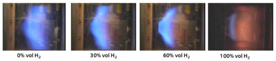 Figure 3. Change in the position of the flame with an increase in the hydrogen content of the fuel according to Siemens [46].
 - Hydrogen corrosion (it will be necessary to change not only the design of the combustion chambers, but also the use of other steels, materials, or coatings).
- An increase in the throughput and power of peripheral systems (such as fuel lines, booster units, control valves, etc.) due to the lower density of hydrogen.
3.2. The Usage of Hydrogen as a Boiler Fuel at Operating TPPs of Russia
The process of hydrogen combustion in boiler units will also require solutions regarding the replacement of burner devices, process control systems, etc., but in general it differs slightly from the combustion of natural gas.
During the technical re-equipment of existing facilities, it should be considered that hydrogen has a wide range of explosion limits and its leakage is much more dangerous than the leakage of traditional fuels. Furthermore, hydrogen has a high flame propagation velocity in a hydrogen torch. The combination of increased burning velocity and increased burning temperature leads to an increase in NOx emissions by 4–6 times, which are significantly more toxic to humans and the surrounding biosphere substance than greenhouse gases. According to research [47], to maintain stable combustion and prevent explosions in boiler furnaces, it is necessary to maintain the combustion process of the methane-hydrogen fraction at increased rates of supply of the methane-hydrogen fraction and technical air [47].
The Russian energy industry has accumulated extensive experience in burning fuel of various compositions in steam boilers: associated petroleum gases, secondary metallurgical gases (converter, coke, and blast furnace gases), residual gases of gas chemical industries, having in their composition from 5 to 40% of the volume content of hydrogen. Therefore, in the Russian Federation, the combustion of blast furnace gas in power boilers is widely used. The volume fraction of hydrogen in the blast furnace gas used is 5.8–6.7%. In addition, in the references of manufacturers, you can find boilers designed to burn coke oven gas (containing on average up to 50–60% hydrogen). However, currently, equipment manufacturers do not have experience in using pure hydrogen in their boilers and pay attention to the lack of an appropriate regulatory framework in the Russian Federation [48,49,50,51].
From the viewpoint of the operation of power plants that have not exhausted their resource, it is possible to transfer operating steam boilers to the combustion of hydrogen-containing fuels. Hydrogen, in a volume fraction of up to 20%, can be mixed with the main fuel (natural gas) without significant changes in the design of boilers. This general approach will require specification in further work [52]:
- The number of changes in the boiler will depend on the boiler model, particularly on the type of burners installed in it (cases in which changes are not required are not excluded).
- The final decision on the proportion of hydrogen in the fuel should be made for each boiler model separately based on the results of the pilot combustion.
Generally, to switch to burning fuels with a large percentage of hydrogen content (from 20% to 100%) at operating boilers, the following key events must be carried out:
- Replacement or modernization of burner devices.
- Development of measures to prevent the possibility of flame spreading upstream, as well as the possibility of its spontaneous combustion.
- Creation of a system for preparing a mixture of hydrogen and natural gas before combustion, including a special system for monitoring the condition of equipment and gas pipelines, development of a mixing device.
- Manufacture of gas pipelines and shut-off valves from materials that avoid hydrogen embrittlement.
- Modernization of the automated control system.
- Increasing the flow sections of gas pipelines and fuel gas treatment system equipment (filters, shut-off valves, heat exchangers) in relation to the flow section of gas pipelines designed to run on natural gas.
Thus, it is currently possible to convert operating gas-and-oil boilers to burning a mixture of natural gas and hydrogen in a volume fraction of up to 20% without significant changes in the design of the furnaces and losses in steam capacity. The changes should concern the burner unit and the installation of an additional shut-off gas valve with an alarm that prevents a reverse flare. When converting solid fuel boilers to gaseous fuel, a full-scale technical re-equipment of both the boiler room (furnace, convective flue, burners) and boiler auxiliary equipment (traction devices, gas and air pipelines, boiler strapping with gas and hydrogen pipelines) will be required.
The combustion technologies of hydrogen-containing gases differ slightly from the combustion of hydrogen directly, and it is theoretically possible to create both a boiler and a gas turbine that can completely run on 100% hydrogen. The main problems are related to the subsequent certification of boilers and the lack of industrial safety requirements of the Russian Federation for hydrogen burners. In addition, it should be borne in mind that one of the significant disadvantages of increasing the proportion of hydrogen in the burned fuel gas is a possible increase in emissions of nitrogen oxides into the atmosphere.
3.3. The Usage of Hydrogen as a Fuel in Fuel Cells at Operating TPPs of Russia
Fuel cells (FC), as well as the production of hydrogen-oxygen steam generators, are identified as one of the main promising global technologies for the production of energy from hydrogen, currently unrealized at the operating thermal power plants of the Russian Federation. This technology can be considered as part of the first stage of the implementation of the hydrogen strategy as add-ons to the existing equipment, allowing to increase the efficiency of the station.
The fuel cell is an electrochemical source of electric current, in which the process involves conversion of fuel energy and oxidizer supplied by the electrodes directly into electrical energy, bypassing the traditional fuel burning processes. The main processes in fuel cells of various types are shown in Figure 4.
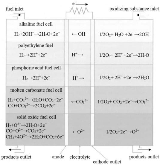
Figure 4.
Main processes in fuel cells of various types [53].
The most promising for stationary power engineering are FCs of the type PAFC, MCFC and SOFC. The FC type PAFC, for example, with a capacity of 200 kW are mass-produced. The cost of such systems is about $3000/kW. The system operates at temperatures of 160–210 °C and has an efficiency of about 35–42%. With the utilization of heat, the efficiency of the fuel cell increases to 80%. The PAFC-type heating elements can be integrated into low-temperature heat supply systems, for example, for heating water for their own needs.
In MCFC-type FCs, expensive platinum catalysts are replaced by cheaper nickel ones. The operating temperature is 600–700 °C. The high temperatures of the process create opportunities for the organization of a full-fledged heat removal during the production of steam or hot water. The efficiency of these thermal power plants is 50–60% and, considering heat recovery, can reach 80% or more. The power extraction (or installed power capacity) from the MCFC type FC is minimal compared to the other types, but this disadvantage is partially compensated for by its relatively lower cost. This fact can be considered as a disadvantage because the use of the FC in this case will be extremely local. The efficiency of the application will be invisible due to the small scale of the MCFC or even the PAFC type FC capacity, which is several hundred orders less than the current electric capacity of operating TPPs (for example, the CHP-21 of St. Petersburg, the installed electric capacity is 500 MW). In this case, the FC will not be able to replace the production of electricity at the existing TPP and it is difficult to find the optimal place for their integration.
The SOFC type FC is a two-phase system (solid phase and gas), instead of the three-phase system in other types of FC, which simplifies and reduces the cost of construction. Such FCs work at high temperatures (1000 °C). The great advantages of this type are the absence of the use of precious metals as catalysts; carbon monoxide, which poisons catalysts in other types of FC, is not a harmful component here. This reduces the requirements for the purity of hydrogen, which are more stringent in other types of fuel cells. High operating temperatures make it possible to obtain process steam, which can be used to generate electricity in steam turbines or for other production needs. The disadvantage of high-temperature heating elements is the long time required to enter the operating mode (up to 12 h), which makes it advisable to use them in stationary power supply systems [15,53,54,55,56,57].
According to [44], fuel and energy sources are currently used in foreign niche markets for backup, highly reliable, or remote, power generation. At this stage of technology development, compared with other single-stage installations that convert fuel energy into electricity, for example, open-cycle gas turbines, the efficiency of the fuel and energy complex is slightly higher and ranges from 30% to 50%. The MCFC and SOFC are the main FC technologies for stationary (industrial) applications, while the PEMFC is used for small residential premises. The MCFC and SOFC operate at higher temperatures, which makes possible their promising application in thermal power engineering.
Improving the efficiency of fuel cells and waste heat utilization are key areas of technology development. Thermal power plants for stationary power plants are at an early stage of commercialization, while the unit investment costs in thermal power plants are still four to six times higher compared to combined cycle (CCGT) installations. With the organization of further research and development, an increase in the scale of the introduction of FC and the start of large-scale production, a decrease in specific capital costs is predicted in the future. For example, the National Laboratory of Energy Technologies (NETL) estimates that the SOFC can achieve investment costs comparable to modern combined cycle installations by 2030. Currently, high investment costs and a low service life are the biggest obstacles to the widespread use of fuel cells. Investment costs largely depend on production costs and can be greatly reduced by scaling. Reducing the volume of precious metals used as a catalyst is also a priority to reduce costs [58].
The technical and economic characteristics of the fuel and energy complex predicted according to [58] for 2030 are summarized in Table 2.
Table 2.
Technical and economic characteristics of TPPs predicted for 2030 based on IEA data from IEA (2015) Projected Costs of Generating Electricity, https://www.iea.org/reports/projected-costs-of-generating-electricity-2015, accessed on 15 May 2022 [58]. All rights reserved.
At the first stage of development, thermal power plants with a single capacity from 200 kW to 1 MW can be widely used as sources of autonomous and, possibly, backup power supply in Russian conditions. The main factors that will determine the use of thermal power plants are the compliance of their capacity with load levels and consumption modes, competitiveness compared to existing sources of energy supply in terms of specific and absolute capital investments and operating costs, the nature, and conditions of the organization of supply to consumers. The main disadvantage of the technology of using thermal power plants is the high cost of the device and its single low power for use in centralized energy.
In order to assess the prospective economic effect of the introduction of FC at operating thermal power plants, we assume that the cost of installing a turnkey thermal power plant will be the minimum value, according to Table 2, namely $1100 per 1 kWh of installed capacity. Let us assume that this cost includes, among other things, fuel-hydrogen.
For achieving the goals within the framework of the first stage of the implementation of the hydrogen strategy, it is advisable to consider the following possible ways of integrating FC at thermal power plants:
- Covering the economic needs of the station, the capacity of which correlates with the possible prospective serial capacity of the fuel and energy complex.
It is assumed that the FC will be installed with a capacity of 1 MW. Currently, such installations are not mass-produced, but there are single prototypes. According to the available working resource of the FC (see Table 2), we will assume that the FC has been working continuously for 5 years. The potential economic effect is achieved by replacing the purchased electricity from the grid to meet the economic needs of the station. In the best case scenario, a simple payback does not occur even without taking into account the cost of hydrogen; a gain of 0.77 million $ does not cover capital expenditures of $1.1 million (see Table 3).
Table 3.
Characteristics of the fuel cell functioning for the purpose of maintenance of the plant.
The effectiveness of the event is influenced by each of the parameters listed in Table 3. For example, when the price of electricity increases more than 0.025 $/kWh in the future beyond the considered 10 years, a simple payback may occur (see Figure 5), the onset of which is also affected by the dollar exchange rate (see Figure 6).
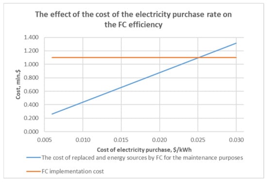
Figure 5.
The effect of the cost of the electricity purchase rate on the FC efficiency in the case of covering the economic needs of the station by FC.
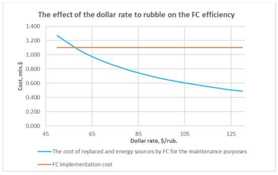
Figure 6.
The effect of the dollar rate to ruble on the FC efficiency in the case of covering the economic needs of the station by FC.
The lifetime duration of the FC also has an impact. Table 2 gives the maximum predicted FC lifetime as 60,000 h, however, with an increase in the FC lifetime duration to over 63,000 h (see Figure 7), a simple payback may occur with the parameters specified in Table 3.
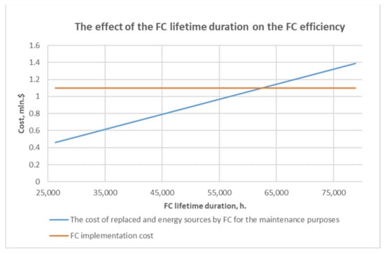
Figure 7.
The effect of the FC lifetime duration on the FC efficiency in the case of covering the economic needs of the station by FC.
In addition, if the unit cost of a fuel cell decreases below $750 per kW, the economic effect of this event is also predicted (see Figure 8).
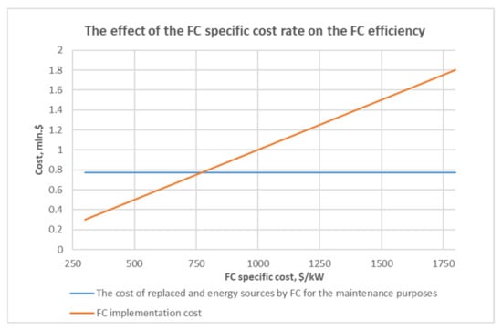
Figure 8.
The effect of the FC specific cost rate on the FC efficiency in the case of covering the economic needs of the station by FC.
Nevertheless, as the FC technology is promising, there is no serial equipment required for use in centralized power generation, and there is no FC in pilot operation, there is also no FC market, and the projected capital expenditures by foreign experts are estimated in the range of +300% for the ones accepted in the calculation (see Table 2).
- 2.
- Replacement of TPP batteries by fuel cells.
Accumulator batteries provide independent (autonomous) power to operational circuits when the AC voltage disappears. During emergency mode, the batteries take the load of all DC electrical receivers, providing relay protection and automation, as well as the ability to turn on and off switches. The maximum duration of the emergency mode is assumed to be 0.5 h for all electrical receivers.
According to the CHP-15 of PJSC TGC-1 (St. Petersburg), batteries of type 12 OCSM 1380 are installed at the station. There is no payback in the accepted source data. There is a possibility that in the future, when the cost indicators of fuel and energy sources and batteries are equalized, fuel and energy sources will be able to replace batteries at thermal power plants (see Table 4).
Table 4.
Characteristics of a fuel cell functioning as a rechargeable battery.
Currently, high investment costs and low service life are the biggest obstacles to the widespread use of fuel cells. Investment costs largely depend on production costs and can be greatly reduced by scaling. Reducing the volume of precious metals used as a catalyst is also a priority to reduce costs. When replacing thermal power plant batteries with a fuel cell, the service life of the thermal power plant does not influence payback. The dollar exchange rate has an impact, but such a strong decline in the dollar, at which a payback could occur (see the Figure 6 from the previous section) is not expected. When studying the impact of the specific cost of fuel cells, we fix the values indicated in Table 4.
When the specific cost of a fuel cell is below $500 per kW, the economic effect of this event is observed (see Figure 9). However, according to Table 2, there will be no prospects for a decline in the near future.
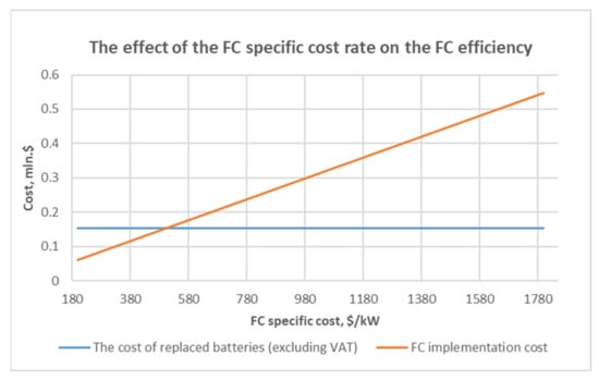
Figure 9.
The effect of the FC specific cost rate on the FC efficiency in the case of replacement of TPP batteries by a FC.
However, summing up the above, it is impractical to consider the FC in relation to the operating TPPs of Russia in the perspective of the next 10 years.
3.4. The Usage of Hydrogen as a Fuel in Hydrogen-Oxygen Steam Generators at Operating TPPs of Russia
The main new element of hydrogen systems for accumulating electricity and covering irregularities in the load schedule (mainly the production of peak and acute peak power) at power plants can be a hydrogen-oxygen steam generator (HOSG) of the high-pressure megawatt power class. The combustion of hydrogen in an oxygen environment allows to obtain high-temperature steam, which can be used at operating thermal power plants of the Russian Federation.
Depending on the required conditions for the use of the HOSG and fuel combustion, the temperature of the uncooled steam can reach 3500–3600 K at a pressure of 6 MPa. That is why the method of cooling the combustion products will have a significant impact on the efficiency of the steam generator. An important problem with the integration of the HOSG with steam turbines is the inability to achieve complete oxidation of hydrogen in the combustion chamber. All technical solutions for temperature reduction involve direct injection of cooling water or water vapor into the combustion products and feeding the resulting mixture into the steam power cycle. The supply of such a mixture to the steam power cycle is unsafe, because it can lead to a dangerous increase in the concentration of unburned hydrogen, creating an explosive mixture, in the flow part of the steam turbine units, as well as in regenerative heaters of steam turbine units.
Hence, it is becoming an urgent task to develop new efficient and safe methods and systems for hydrogen combustion in an oxygen environment for hydrogen steam overheating in the power plant cycle. The development of the HOSG uses the experience of rocket (liquid-jet engines) and aviation technologies. In recent years, Russian specialists have developed several experimental HOSGs with a thermal capacity of up to 25 MW.
According to the available research, at present, the stage of research work in the creation of the HOSG has been almost completed and experimental data on the dynamic characteristics and other technical parameters of the promising HOSG have been obtained. Several tasks still need solving in order to move from prototypes to large-scale use of the HOSG. For a more accurate study and completeness of the combustion of hydrogen in oxygen, further experimental studies are necessary [59,60].
The main promising areas of the use of HOSG in the energy sector are:
- Additional accumulating superstructures to produce peak capacities. It is possible to modernize operating power plants, allowing fulfilling the power reserves of the operating equipment. Increasing the temperature of superheated steam by using the HOSG with the appropriate reconstruction of the central heating system of turbines, fittings, and sections of steam pipelines to work with higher operating temperatures.
- The use of hydrogen superstructures to increase the manoeuvrability and efficiency of the CCGT, as well as to increase the overall stability of power grids. An important property of the HOSG is a quick start with an output to the nominal mode in less than 10 s. Another important property for power control is the ease of obtaining the required temperature of the generated steam, which is determined by the amount of injected ballast water.
According to [61,62,63], additional electrical power when using the HOSG can be obtained due to both an increase in steam consumption per cycle and its additional overheating (for example, when mixed with steam from a heat recovery boiler). The schematic diagram is shown in Figure 10. All this leads to an increase in the efficiency of the turbine. It is most thermodynamically efficient to use hydrogen fuel with a combined increase in steam consumption and its additional overheating.

Figure 10.
Diagram of the connection of the HOSG to the steam turbine of a Combined-Cycle Power Unit [61]. 1, hydrogen-oxygen steam generator; 2, steam lines from the boiler; 3, steam turbine; 4, house steam header; 5, generator; 6, electric self-service line; 7, electric power distribution network.
Basing on the above, we will consider the effectiveness of the use of the HOSG on the most common power equipment in the operating thermal power plants of the Russian Federation: a combined-cycle unit with a combined-cycle gas plant CCGT-450 and a steam turbine unit with turbines T-100-130 and T-250/300-240.
- Implementation of HOSG technology into existing schemes of thermal power plants with CCGT.
The introduction of the HOSG technology into existing schemes of thermal power plants with CCGT is similar to the use of fuel afterburning technology in modern utilization-type CCGTs. This allows to increase the generated electric power with a corresponding decrease in generation efficiency [61,64]. The temperature of the steam supply to the cycle from the HOSG should exceed 700 °C to achieve efficiency. The HOSG itself allows obtaining steam with temperatures, thanks to which an increase in the thermodynamic efficiency of the cycle is achieved. However, it is impossible for now to use steam with such temperatures at operating thermal power plants—the global temperature of mass-produced steam pipelines is 600–610 °C. The steam temperature limit is 565 °C in the Russian Federation. In addition, according to [65], at this stage of the development of metal production technologies in the Russian Federation, the point when production will be economically profitable is between 600 °C and 700 °C. Even at 700 °C, the cost will be more than on units that work for a long time.
Therefore, the HOSG technology is not recommended at operating TPPs with CCGT units as part of the first stage of the implementation of the hydrogen strategy. It is a promising technology for operating thermal power plants and can be implemented, for example, in the construction of new CCGT units after the serial development of high-temperature steam pipelines in the Russian Federation.
- 2.
- Implementation of the HOSG technology into the existing schemes of thermal power plants with a T-100 turbine and a T-250 turbine.
The CHP-21 and CHP-22 of PJSC “TGC-1” St. Petersburg were studied as an aim for assessing the potential effectiveness of the use of the HOSG (see Table 5). Heatwaves with outgoing gases are assumed to be 5.4% (from the experience of thermal calculations of boiler units).
Table 5.
Characteristics of the equipment installed at CHP-21 and CHP-22 (St. Petersburg).
There are two possible options for integrating the HOSG into the thermal scheme of the steam power unit:
- 2.1.
- Replacement of a part of the steam generated by the boiler unit with the help of the HOSG. In this case, the generated electric power remains nominal and the steam capacity of the steam boiler decreases.
A feature of the HOSG is that there are no losses with outgoing gases, unlike traditional boilers, because when hydrogen is burned, steam is formed, which is used in the cycle, and is not released into the environment. Thus, the efficiency of the HOSG will be higher than the efficiency of a traditional steam boiler.
With the use of a HOSG with a thermal power of 25 MW, heat losses with exhaust gases in a steam boiler will decrease by 1.35 MW, which is equivalent to saving natural gas in the amount of 2.51 thousand nm3/h. The fuel costs per boiler unit in the variants with and without the use of HOSG at CHP-21 and CHP-22 are presented in Table 6.
Table 6.
Fuel costs of using and not using HOSG.
Not considering the capital costs of installing the HOSG, the total fuel costs in the version with the HOSG in the current tariff environment exceed the costs without using the HOSG. In the conditions of the accepted initial data, there is no payback.
The price of hydrogen has a significant impact on the effectiveness of the event (operating costs), regardless of the type of steam boilers under consideration. The price of natural gas and the dollar exchange rate also have an impact, but it is unnoticeable against the background of the high cost of hydrogen. When studying the influence of the purchase price of hydrogen on the economic effect of the event, we fix the parameters given in Table 6.
With the projected price of hydrogen stored at thermal power plants not exceeding $200–250/ton, the introduction of this technology will lead to an economic effect (see Figure 11).
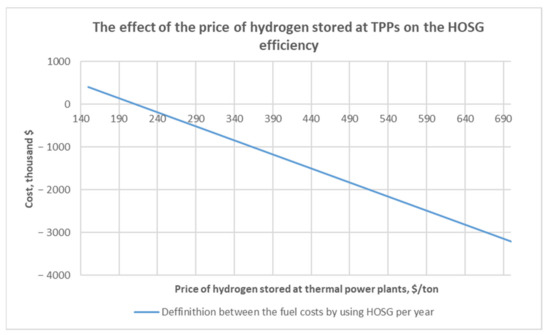
Figure 11.
The effect of the price of hydrogen stored at TPPs on the HOSG efficiency in the case of replacement of a part of the steam generated by the boiler unit with the help of the HOSG.
It should also be considered that the HOSG on steam power units is similar to the conversion of boilers to hydrogen in terms of fuel consumption. This will require, in addition to creating an infrastructure for storing hydrogen as the main fuel, which is already problematic in the conditions of an existing facility, an additional infrastructure for storing pure oxygen.
- 2.2.
- Superheating of the hot steam at the outlet of the boiler unit to the maximum currently possible temperature of 565 °C [60].
In this case, the steam capacity of the boiler unit is constant, and the electric power of the turbine increases. Currently, the temperature of steam entering the turbine at CHP-21 is 540 °C, and the turbine at CHP-22 is also 540 °C (see Table 5). Economic efficiency can be achieved due to an additional gain in electrical power due to an increase in the available heat transfer of the turbine. At the same time, hydrogen is consumed at the HOSG (see Table 7).
Table 7.
Annual fuel costs for HOSG and the gain from the additional electricity produced at CHP-21 and CHP-22.
The total fuel costs in the variant with the HOSG in the current tariff environment exceed the gain from the use of the HOSG. In addition, this technical solution will require the replacement of the high-pressure cylinder of the turbine to be able to work on fresh steam with a temperature of 565 °C, estimated at $3.64 million for the T-100-130 turbine; there is no cost data for the CHP-22. It is also necessary to purchase the HOSG unit at a cost of $2.42 million (expert assessment based on [59,60,61,62,63]).
With such objective-setting, the carbon tax will not have an impact on economic efficiency, as in the basic version and in the version with the HOSG, CO2 emissions will be equal. The effect is achieved only by increasing the electrical power or reducing the cost of hydrogen. When studying the effect of these parameters on efficiency, the values given in Table 7 are recorded.
Therefore, when the cost of hydrogen decreases below $300 per ton, a positive effect appears. With the cost of hydrogen $200 per ton, the simple payback, for example, for CHP-22, occurs in less than 8 years (see Figure 12), and with an increase in the cost of the released e/e to 0.048 $/kWh, the simple payback of the event, for example, for CHP-21, will be 4 years (see Figure 13).
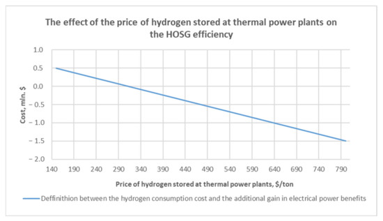
Figure 12.
The effect of the price of hydrogen stored at thermal power plants on the HOSG efficiency in the case of superheating of the hot steam at the outlet of the boiler unit to the maximum currently possible temperature of 565 °C.
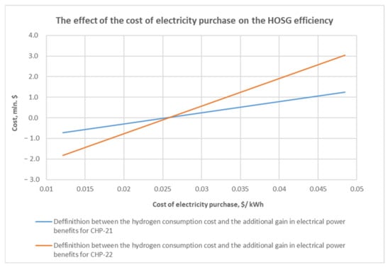
Figure 13.
The effect of the cost of electricity on the HOSG efficiency in the case of superheating of the hot steam at the outlet of the boiler unit to the maximum currently possible temperature of 565 °C.
This technical solution has a thermodynamic effect and is theoretically feasible in the conditions of operating steam-power cycle thermal power plants when solving the existing number of problems of the HOSG, after the appearance of serial production and the experience of introducing the HOSG to existing energy facilities. However, within the framework of the first stage of the implementation of the hydrogen strategy, it is economically impractical to implement this event.
3.5. Hydrogen Storage at Operating TPPs of Russia
To organize the process of hydrogen combustion at the operating TPPs of Russia, it is necessary to study the issue of hydrogen transportation from the place of production (or storage) directly to the site of the facility. The proper organization of its storage in accordance with the requirements of the legislation of Russia, dictating the need to create fuel reserves at TPPs [66].
The low density of hydrogen gas, the low temperature of its liquefaction, as well as the high explosion hazard combined with the negative impact on the properties of structural materials are at the forefront the problems of developing economically and technically efficient and safe hydrogen storage systems. It is these problems that are holding back the development of hydrogen energy and technology at the present time [67].
Hydrogen can be stored in gaseous, liquid, and cohesive form in solid or liquid carriers. In addition, it can be stored in the form of chemical compounds that release hydrogen during decomposition. The following most frequently encountered hydrogen storage technologies can be found in the specialized literature:
- Storage of compressed hydrogen gas in high-pressure tanks.
- Storage of liquid hydrogen.
- Storage of hydrogen gas at normal and elevated pressure in underground storage facilities.
- Storage of hydrogen in the form of various types of hydride carriers in microspheres in capillary structures, etc.
As part of the first stage of the implementation of the hydrogen strategy on the scale of TPPs, it is impractical to consider small-scale hydrogen storage systems. These systems include storage methods in the form of chemical compounds, as well as untested solutions, such as hydrogen storage in underground storage facilities. With the accumulation of information about the specifics, the experience of storing hydrogen in underground storage facilities, the applicability of geological conditions and the feasibility of this type of storage under operating production conditions (TPP) and also when adapting to the use of small-scale hydrogen storage systems in centralized energy, these storage methods can be further considered on the scale of TPP. The most promising is the consideration of compressed and liquid hydrogen storage technologies.
Hydrogen gas storage is fairly simple and inexpensive; the technology is well developed. It must be compressed for storage. It takes much more energy to compress hydrogen than methane. Isothermal compression of the gas can be achieved only in the case of continuous cooling, which is difficult to implement in practice. Usually, multi-stage compression with intermediate cooling is used. Hydrogen quickly transfers the heat of compression to the walls of the cooler, and the temperature after each compression stage ideally decreases to the initial one.
The technology for storing hydrogen under pressure in tanks is similar to the technology for storing natural gas. The main capital and operational costs when using gaseous fuel storage systems are the compressors.
As a rule, cylindrical cylinders, or containers, in the form of large-volume pipes are used. If conventional steel cylinders filled with hydrogen with a pressure of up to 20 MPa are used, 4 kg of hydrogen occupy a volume of 225 L. Systems of gas-cylinder storage of hydrogen under pressure up to 40 MPa, including curved titanium cylinders, have been created in Russia. However, even for cylinders made of new composite materials, the stored energy density is significantly less than the value of liquid hydrogen. Cylinders withstanding up to 70 MPa have been developed from composite materials reinforced with carbon fibres; work continues on optimizing materials and reducing cost. Nevertheless, even at such a high pressure, the energy density is low compared to other fuels, and the volumes of these gas cylinders are low for use for fuel storage at thermal power plants. It is quite common in industry to store hydrogen gas in large gas tanks under pressure. The disadvantage of gas tanks is low tightness. Thus, the permissible leakage of hydrogen from wet gas tanks is 1.1–1.65% (per nominal volume of the gas tank) per day [56,68].
Because hydrogen gas has a low density, it is advantageous to store it in such containers only in relatively small quantities. If the pressure is increased (above 10 MPa), for example, to a pressure of about 100 MPa, then difficulties arise, primarily because hydrogen corrosion of carbon steels begins at such high pressures, as well as a significant increase in the cost of such containers [54,67]. Currently, the maximum capacity of hydrogen storage tanks produced in Russia does not exceed 200 m3.
The benefits of the liquid hydrogen storage method are large capacity values by weight and volume (density of liquid hydrogen is 70.8 kg/m3). However, there are strict requirements for materials for cold resistance, constant cooling (up to 20 K) and effective insulation are required. In order to prevent local overheating, vessels filled with liquid hydrogen should be pre-cooled, which leads to high hydrogen consumption for cooling the tank. The second problem that arises is evaporation losses. In addition, the storage of liquefied gas is unsafe: evaporating hydrogen must be captured and re-liquefied.
Various refrigeration cycles can be used for liquefaction. The simplest cycle is the Linde cycle or the Joule–Thompson isenthalpic expansion cycle based on the throttling effect, as well as other cycles based on the isentropic expansion of hydrogen with the production of external work in the expander [54,67,69].
The following basic requirements apply to liquid hydrogen storage tanks:
- The design of the tank must ensure its long-term safe operation.
- The consumption of liquid hydrogen for pre-cooling of the storage should be minimal.
- The tank must be equipped with devices for rapid filling and rapid delivery of the stored product.
Liquid hydrogen storage tanks are either cylindrical or spherical. Storage of a larger volume—up to 5000 m3—is made in the form of a sphere to reduce evaporation losses [54].
While considering the technical feasibility of using hydrogen as fuel at operating thermal power plants, it is necessary to consider the following circumstances:
- Hydrogen can be used on existing TPP equipment only in a mixture with gas fuel in volume concentrations up to 20%, but not in pure form.
- The use of hydrogen together with the existing reserve fuel of the CHP-fuel oil (fuel warehouses with a stock are available at site of facility) on the operating equipment is practically excluded.
These aspects determine that the use of hydrogen as a backup fuel for thermal power plants is possible only in combination with natural gas (which should also be a backup fuel). In this case, to ensure the transfer of the TPP operation to reserve fuel (when the supply of mains gas is stopped), it is necessary to create storage reserves for both hydrogen and natural gas at the station in quantities regulated by the legislation of the Russian Federation [66]. Using hydrogen as the primary fuel makes the liquid fuel warehouse greatly over-sized, and, consequently, the costs of its creation and maintenance (in this case, the fuel warehouse is calculated for 30 days, this will require an increase in the tank fleet).
Table 8 shows the number of hydrogen storage tanks (20% of the volume fuel consumption) as the main and backup fuel, excluding natural gas storage tanks, as well as the areas required to accommodate the hydrogen storage facilities for the Northern CHP-21 of PJSC TGC-1 (St. Petersburg).
Table 8.
The number of hydrogen storage tanks as the main and backup fuel, as well as the areas required to accommodate the hydrogen storage facilities.
Storing compressed hydrogen in tanks with a maximum capacity of 200 m3 of hydrogen as a backup fuel, not to mention storing hydrogen as the main fuel, is practically impossible on the scale of thermal power plants. It is not very realistic to implement the placement of the required area of the tank farm for storing hydrogen as the main fuel for both types of storage under consideration both at the CHP-21, which has free areas, and at any of the operating sites of the TPP of the Russian Federation. Welded gas tanks, which could be an alternative to a tank farm, do not have sufficient tightness (complete emptying of the tank takes 2.5 months).
Considering the limited territorial capabilities of the sites of operating TPPs, the only practical solution is to create warehouses of liquefied hydrogen and liquefied natural gas (LNG) in the required calculated quantities (in aggregate terms of conventional fuel) for their subsequent mixed use as a reserve energy fuel for the thermal power plants.
The LNG is stored in tanks that provide high thermal insulation, as when a small amount of heat is received, part of the liquid turns into a gaseous form, which leads to gas leaks. Storage facilities are designed according to the vessel-in-vessel principle and are made of metals or steels with a low temperature coefficient of expansion, which do not collapse when interacting with liquefied hydrocarbons (aluminium or steel with 9% nickel added). Depending on the operating conditions, concrete or a construction composite made of concrete and steel can also serve as the materials of the external tank. The space between the tanks is filled with a special thermal insulation material and vacuum. In recent years, it has become possible to build large underground storage facilities with a volume of up to 200 thousand m3 [70].
In order to store LNG reserves in the vicinity of the thermal power plant, it is advisable to use larger storage facilities, for example, commensurate with isothermal type tanks [71], located, for example, in the port of Vysotsk at the Cryogaz-Vysotsk LNG plant with a capacity of 42,000 m3. The diameter of such a storage is about 46 m [72].
The loss of evaporated gas for LNG tanks is usually no more than 0.03% per day. The evaporated gas is captured, liquefied, and returned to the LNG storage tank. The evaporated gas of both LNG tanks and liquid hydrogen storage tanks must be liquefied.
To use hydrogen gas as a fuel, its regasification from the liquid state is required. When necessary, LNG and liquefied hydrogen are converted into a gaseous form; the conversion procedure is carried out in an evaporative system. Regasification schemes of directly liquefied hydrogen rarely can be found in the specialized literature.
There is a known method of regasification of the cryoproduct by heat exchange with the environment. The disadvantage of this method is the loss of cold accumulated in the cryoproduct, but on the other hand, the atmospheric evaporator does not require fuel or electricity to work, heat flows from the environment are used due to the developed heat exchange surface [73]. Atmospheric evaporators have become widespread, as they provide the most economical and environmentally friendly way of gasification of cryogenic liquids. These regasifiers are used at low performance or as a backup line to ensure peak loads. Atmospheric evaporators are most advantageous in the equatorial climate, where the air temperature is kept at the same level all year round. In addition, a significant disadvantage is the impressive overall dimensions, which requires a significant area for the placement of equipment.
Liquid-type evaporators use liquid as a heat carrier, which circulates in a closed system and transfers heat to liquefied gas. The following coolant is usually used: glycol, hydrocarbon refrigerants (propane, butane, or mixed refrigerants) or hot water [74].
Atmospheric evaporators at operating thermal power plants, despite their simplicity and environmental friendliness, have limited application potential, as they have large overall dimensions, and, accordingly, require a significant area for the placement of equipment. In the cramped conditions of the current production, it is recommended to use liquid-type evaporators using hot water in the form of a coolant. To this end, a part of the mains water intended for heat supply to consumers can be used at thermal power plants (see Figure 14).
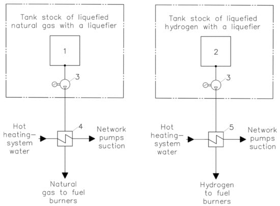
Figure 14.
LNG and hydrogen regasification scheme. 1, LNG tanks; 2, liquefied hydrogen tanks; 3, low pressure cryogenic pumps; 4, LNG regasification units; 5, liquid hydrogen regasification units.
In the case of replacing the installed fuel storage facility with storage of liquefied natural gas and hydrogen, the total supply of cryogenic gases should be equal in terms of the specific calorific value of the fuel oil storage based on a mixture of hydrogen (20% of the volume flow) and natural gas (80% of the volume flow).
In such case, the infrastructure of the liquid fuel reserve economy consists of (see Figure 14):
- Cryogenic tanks.
- Liquefiers of steam cryogenic gases.
- Cryogenic pumps.
- Hydrogen and LNG regasification plants powered by mains water after mains pumps with the return of the heating medium to the return line.
- Pipeline strapping.
- LNG and hydrogen filling stations.
While replacing the installed fuel oil reserve economy with an LNG and liquefied hydrogen storage system, the main energy effects are:
- Saving on maintenance steam of the oil fuel facility.
- Savings on steam satellites of fuel oil pipelines and on steam cooling of fuel oil injectors.
- Saving on electricity for the drive of recirculation pumps and main fuel oil feed pumps.
- Saving steam for heating fuel oil to operating temperature.
- Saving on a couple of own needs of the electrolyze unit.
- The expenses for the management of LNG and liquefied hydrogen consist of the cost of spent fuel per year, the cost of electricity for liquefaction of steam cryogenic gases, the cost of heat for regasification when using reserve fuel.
Additional resource consumption is associated with:
- Electricity costs for liquefaction of steam cryogenic gases.
- Heat costs for regasification when using reserve fuel (hot water).
With the existing conjuncture for energy resources in the Russian Federation (see Table 9), it is estimated that the specific economic effect of the event on the transition to storage of cryogenic fuel instead of fuel oil storage is from $485 to $727 per MW of installed capacity of thermal power plants (see Table 10).
Table 9.
Initial data for calculating the storage system of liquefied hydrogen and LNG as a backup fuel.
Table 10.
Characteristics of the measure for the replacement of the fuel oil storage facility of TPP with the LNG and hydrogen storage facility.
This effect depends on the amount of fuel oil stored at the plant, the scheme of preparation of reserve fuel, as well as on the number of hours of use of reserve fuel per year (see Figure 15). When studying the influence of the purchase price of hydrogen, we fix the values taken in Table 9. An increase in the cost of hydrogen as a percentage of the accepted price of 120%, 140%, 160% was considered. The change in the cost of hydrogen does not significantly affect the operating costs of the reserve fuel economy (see Figure 15). This is due to low fuel combustion when using liquefied hydrogen and LNG as a reserve. The main component of expenses is accounted for by the costs of electricity and heat.
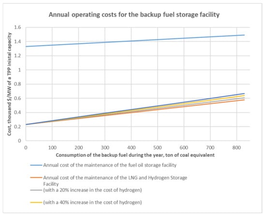
Figure 15.
Annual operating costs for the backup fuel storage facility (the fuel oil storage facility and the LNG and liquid hydrogen storage facility).
3.6. Specifics of Hydrogen Transportation via Gas Pipelines
In order to remove restrictions on the use of hydrogen as the main fuel in a mixture with natural gas at operating thermal power plants, it is necessary to lay a gas pipeline from the places of hydrogen production or storage to the station site. One possible option is to add hydrogen to an existing (or projected for non-gas-fired thermal power plants) natural gas pipeline and transport it through gas networks (during storage and regasification of hydrogen outside the thermal power plant sites).
The addition of hydrogen to natural gas and its transportation through gas networks are considered today as one of the important steps towards renewable energy. In European countries, it is proposed to produce hydrogen at zero or even negative tariffs using the energy generated at night by wind farms, and the resulting hydrogen is mixed with natural gas into the gas supply system. In this case, the gas pipeline system will play the role of a hydrogen accumulator [54].
In the paper [76], the experience of a gas distribution system with a 20% volume fraction of hydrogen was analysed. From 2002 to 2006, the European Commission participated in the financing of the NaturalHy project. The NaturalHy results also show that the impact of hydrogen on materials used in the construction of natural gas pipelines can be reduced through appropriate measures. Modifications are mainly required for steel trunk pipelines, however, no insurmountable obstacles to pumping hydrogen into gas distribution networks have been identified. Hydrogen was mixed with natural gas with a gradual increase in its concentration from 5 to 20%. Experimental and control gas pipelines were added to the operating natural gas distribution network. These sites of the same type were built for testing from the same set of components: pipes of different materials, connections, regulators, and meters. In the process of implementing the project, there were no security problems and interruptions in gas supply. Following four years of exposure to hydrogen-enriched natural gas, no effect of hydrogen on the most important properties of the materials studied was revealed. A problem is that when hydrogen is distributed, its penetration through the wall of the pipeline is possible. For this reason, gas permeability tests were conducted, which showed a relatively low level of penetration, which did not affect safety. An external inspection also revealed no defects caused by hydrogen exposure. Nevertheless, there is still concern about the possibility of using such a mixture of gases by industrial consumers. There is a possibility that their equipment may need to be readjusted or upgraded to work on hydrogen-enriched natural gas.
Similar projects are taking place in other countries. In the UK, the HyDeploy pilot project has been implemented to introduce green hydrogen into the gas network, which will be used for heating. In France, the company Grhyd Project ENGINE is testing the injection of green hydrogen into the gas distribution network of Le Petit Village and a gas station for buses. The initial concentration of green hydrogen will be 6%, which will eventually be increased to 20%. In Australia, ARENA has provided funding to the gas network to establish an Australian Hydrogen Centre (AHC) to explore the possibility of adding 10% hydrogen to natural gas networks for selected regional cities in South Australia and Victoria. In Italy, Snam has doubled the volume of hydrogen mixture in its gas transmission network in Contursi Terme from 5% to 10%. This was done just a few months after a 5% hydrogen mixture was introduced into the natural gas network for the direct supply of two companies in Contursi Terme [77].
Therefore, the combined transportation of hydrogen and natural gas in shares of 20% and 80%, respectively, according to the experience of European countries, will not require a significant change in the standard equipment for creating a gas transmission system and can be considered as a promising way of using hydrogen together with natural gas. It is especially essential in non-gasified areas of the Russian Federation, where the appearance of terminals for receiving and transhipment of liquefied natural gas is possible. A mixture of hydrogen and natural gas can be used to convert operating thermal power plant equipment currently operating on fuel oil or coal to a more environmentally friendly fuel. In addition, such a solution will improve the efficiency of this equipment.
Considering the limited territorial capabilities of the sites of operating thermal power plants, when implementing the MHM gas transmission system and organizing the supply of MHM to the TPP site by two independent gas pipelines, hydrogen storage at the station will not be required. While it becomes possible to use MHM not only as a backup, but also as the main fuel. According to experts [78], the cost of transporting hydrogen per 100 km by pipeline transport (in compressed form) is $0.4/kg. Simultaneously, the cost of transportation by road (in liquefied form in cryogenic tanks) is 0.1 $/kg (excluding the cost of capital and operating costs for the construction and maintenance of the liquefied hydrogen economy). Nevertheless, hydrogen transportation via gas pipelines can be more cost-effective than other types of transport when the power plant site is located near the hydrogen production, reception, or transhipment terminals, as when hydrogen is delivered by road and rail, unlike the pipeline method, operating costs for storage of reserve fuel have a significant impact. The unit cost of hydrogen storage is estimated at $1.16/kg of hydrogen per year (for example, the CHP-21 of St. Petersburg).
4. Conclusions
- Feasible. For implementing decarbonization and hydrogen energy strategies, as well as the compliance of the Russian Federation with the global decarbonization trend, it is possible to implement projects on testing the use of hydrogen as a fuel at operating TPPs.
- Mix with natural gas. For the implementation of the goals of the first stage of the hydrogen strategy implementation at operating gas fired TPPs, it is advisable to consider the technology of burning a mixture of hydrogen and natural gas in gas turbines and gas-oil steam boilers in volume fractions of 20% and 80%, respectively. This ratio can be burned in existing installations with minimal structural changes to the main boiler and gas turbine equipment without replacing it. In the future, after solving several problems, it is possible to create both a gas turbine and steam and hot water boilers that completely burn 100% hydrogen and the use of this equipment.
- Convert non-gas-fired TPPs. In the case of non-gas-fired thermal power plants, it is advisable to consider transferring them to the combustion of hydrogen and natural gas, with the creation of a gas transmission system of hydrogen and natural gas, in shares of 20% and 80%, respectively. The storage site of liquefied natural gas and hydrogen can be located either at the thermal power plant itself, or at the sites of LNG and hydrogen transhipment terminals (if there is a prospect of creating such transit ports). A mixture of hydrogen and natural gas can be used to transfer existing power equipment of thermal power plants, especially those operating on fuel oil, to more environmentally friendly fuel. When this is the situation, with a relatively close location of the TPP site, it is possible to refuse to store fuel directly at the power plant. The positive economic effect of the implementation of the use of hydrogen is possible due to savings in the cost of storing and using the main and reserve fuel. At the same time, the conversion of solid fuel boilers to hydrogen gas fuel in terms of structural changes is closer to the complete replacement of boiler units, an order of magnitude higher than the cost of replacing burner devices, and it seems impractical within the first stage of decarbonization of power engineering.
- Hydrogen storage options. The option of storing hydrogen gas as both the main and reserve fuel at this stage of technology development, in view of the required area of the tank farm exceeding the available areas of any of the operating TPP sites, is not applicable. Hydrogen storage systems in the form of various types of carriers (metal hydrides, borohydrides, and amides) are difficult to adapt in the conditions of thermal power plants due to their low capacity. It is possible to use it in the future after increasing the unit energy intensity of the equipment and reducing the cost. Storage of hydrogen gas at normal and elevated pressure in underground storage facilities requires several studies and testing. It is possible in the conditions of new industrial construction with the proper development of technology. Currently, the usage of these technologies is not recommended due to the limited time frame of implementation within the first stage of the implementation of the hydrogen strategy.
- Warehouses of liquefied hydrogen and LNG. Considering the limited territorial capabilities of the sites of operating thermal power plants for the implementation of the goals of the first stage of the implementation of the hydrogen strategy, the only practical solution for using hydrogen as a backup fuel is to create warehouses of liquefied hydrogen and LNG in the necessary calculated quantities for the subsequent use of their mixture as a backup energy fuel. It is estimated that the specific economic effect of the event on the transition to storage of cryogenic fuel instead of fuel oil storage is from $485 to $727 per MW of installed capacity of thermal power plants.
- Hydrogen as a main fuel. It is impossible to use hydrogen as the main fuel in the conditions of operating thermal power plants, as it is not practicable to place a tank farm at the available sites of any of the operating thermal power plants. In the case of the prospective development of the MHM gas transmission system and the organization of the MHM supply to the TPP site by two independent gas pipelines, hydrogen storage at the station will not be required–the restriction on the use of MHM as the main fuel will be lifted. It is recommended to consider the possibility of replacing the economy of reserve liquid fuel (fuel oil) with the technology of storage of reduced hydrogen in combination with natural gas (which is also stored in liquefied form and is a backup), or the creation of a gas transmission network with a fraction of hydrogen.
- Fuel cells. Fuel cells are currently not applicable to operating thermal power plants due to low unit capacity and short FC lifetime duration. The limiting factor is also the high cost of the device (the unit cost, according to the research results, should be lower than 500–750 $/kW), and the lack of large-scale technologies. In the future, they can be used as sources of autonomous and, possibly, backup power supply after increasing the unit energy intensity of the equipment and reducing the cost, since now there is no economic effect within the first stage of the implementation of the hydrogen strategy.
- HOSG technology. The implementation of the HOSG technology into operating thermal power plant schemes of a similar afterburning technology would lead to a decrease in the efficiency of the cycle. An increase in the steam temperature in front of steam turbines by means of the HOSG for operating steam power units is limited due to restrictions on the maximum temperature of steam pipelines. In addition, the HOSG on steam power units is similar to the conversion of boilers to hydrogen in terms of fuel consumption. This will also require the creation of an infrastructure for the storage and delivery of hydrogen as the main fuel, which in the conditions of the existing facility can be provided only with the appearance of a gas transmission system of the Ministry of Internal Affairs. Moreover, the existing HOSG technology is small-scale. The technology is promising, requires several studies and is not recommended for implementation at the first stage of the first hydrogen strategy.
Author Contributions
Conceptualization, D.K. and D.T.; methodology, M.T.; formal analysis, Y.K.; investigation, D.K. and D.T.; resources, I.A.; data curation, A.K.; writing—original draft preparation, Y.K.; writing—review and editing, A.A.; visualization, K.K.; supervision, K.K.; project administration, I.V. and A.A.; funding acquisition, I.V. and A.K. All authors have read and agreed to the published version of the manuscript.
Funding
This research was done at Peter the Great St. Petersburg Polytechnic University and supported under the strategic academic leadership program ‘Priority 2030’ of the Russian Federation (Agreement 075-15-2021-1333 dated 30 September 2021).
Institutional Review Board Statement
Not applicable.
Informed Consent Statement
Not applicable.
Data Availability Statement
The data are not publicly available due to privacy considerations.
Conflicts of Interest
The authors declare no conflict of interest.
References
- The Rio Declaration on Environment and Development. Available online: https://www.un.org/ru/documents/decl_conv/declarations/riodecl.shtml (accessed on 12 September 2021).
- The United Nations Framework Convention on Climate Change (UNFCCC). Available online: https://www.un.org/ru/documents/decl_conv/conventions/climate_framework_conv.shtml (accessed on 12 September 2021).
- The Kyoto Protocol. Available online: https://www.un.org/ru/documents/decl_conv/conventions/kyoto.shtml (accessed on 12 September 2021).
- The Paris Agreement. Available online: https://unfccc.int/files/meetings/paris_nov_2015/application/pdf/paris_agreement_russian_pdf (accessed on 12 September 2021).
- A European Green Deal. Available online: https://ec.europa.eu/info/strategy/priorities-2019-2024/european-green-deal_en (accessed on 12 September 2021).
- EU Strategy on Energy System Integration. Available online: https://ec.europa.eu/energy/topics/energy-system-integration/eu-strategy-energy-system-integration_en (accessed on 19 September 2021).
- European Clean Hydrogen Alliance. Available online: https://ec.europa.eu/growth/industry/strategy/industrial-alliances/european-clean-hydrogen-alliance_en (accessed on 11 September 2021).
- Russian Federal Law, No. 296 on Limiting Greenhouse Gas Emissions. Available online: http://publication.pravo.gov.ru/Document/View/0001202107020031 (accessed on 12 September 2021).
- Decree of the Government of the Russian Federation No. 3052-r Dated 29 October 2021. On the Approval of the Strategy of Socio-Economic Development of the Russian Federation with Low Greenhouse Gas Emissions until 2050. Available online: https://rospatent.gov.ru/ru/documents/rasporyazhenie-3052-r-29102021 (accessed on 1 February 2022).
- Yulkin, M.A. Global Decarbonization and Its Impact on the Russian Economy. ANO “Environmental Investment Center”. Available online: http://downloads.igce.ru/news/Yulkin_M_A_ext_abstract_IGCE_06022019.pdf (accessed on 10 September 2021).
- Decree of the President of the Russian Federation No. 208 dated 13 May 2017. On the Approval of the Economic Security Strategy of the Russian Federation for the Period up to 2030. Available online: http://www.kremlin.ru/acts/bank/41921 (accessed on 12 September 2021).
- Decree of the Government of the Russian Federation No. 1523-r of 9 June 2020. On the Approval of the Energy Strategy of the Russian Federation for the Period up to 2035. Available online: https://docs.cntd.ru/document/565068231 (accessed on 12 September 2021).
- Decree of the President of the Russian Federation No. 176 dated 19 April 2017. On the Strategy of Environmental Safety of the Russian Federation for the Period up to 2025. Available online: http://government.ru/docs/all/111285/ (accessed on 15 October 2021).
- Decree of the Government of the Russian Federation No. 2162-r of 5 August 2021. On Approval of the Concept of Development of Hydrogen Energy in the Russian Federation. Available online: http://government.ru/docs/42971/ (accessed on 15 October 2021).
- Sinyak, Y.V. Prospects for the use of hydrogen in decentralized power and heat supply systems. Stud. Russ. Econ. Dev. 2007, 18, 264–275. [Google Scholar] [CrossRef]
- Report on the State of Heat Power and District Heating in the Russian Federation in 2019. Available online: https://minenergo.gov.ru/node/20641 (accessed on 1 February 2021).
- Balasubramanian, B.; Ortiz, A.L.; Kaytakoglu, S.; Harrison, D.P. Hydrogen from methane in a single-step process. Chem. Eng. Sci. 1999, 54, 3543–3552. [Google Scholar] [CrossRef]
- Abbas, H.F.; Wan Daud, W.M.A. Hydrogen production by methane decomposition: A review. Int. J. Hydrogen Energy 2010, 35, 1160–1190. [Google Scholar] [CrossRef]
- Romano, M.C.; Cassotti, E.N.; Chiesa, P.; Meyer, J.; Mastin, J. Application of the Sorption Enhanced-Steam Reforming process in combined cycle-based power plants. Energy Procedia 2011, 4, 1125–1132. [Google Scholar] [CrossRef] [Green Version]
- Carapellucci, R.; Giordano, L. Upgrading existing gas-steam combined cycle power plants through steam injection and methane steam reforming. Energy 2019, 173, 229–243. [Google Scholar] [CrossRef]
- Navarro, R.M.; Peña, M.A.; Fierro, J.L.G. Hydrogen production reactions from carbon feedstocks: Fossil fuels and biomass. Chem. Rev. 2007, 107, 3952–3991. [Google Scholar] [CrossRef]
- He, M.; Hu, Z.; Xiao, B.; Li, J.; Guo, X.; Luo, S.; Liu, S. Hydrogen-rich gas from catalytic steam gasification of municipal solid waste (MSW): Influence of catalyst and temperature on yield and product composition. Int. J. Hydrogen Energy 2009, 34, 195–203. [Google Scholar] [CrossRef]
- Janajreh, I.; Raza, S.S.; Valmundsson, A.S. Plasma gasification process: Modeling, simulation and comparison with conventional air gasification. Energy Convers. Manag. 2013, 65, 801–809. [Google Scholar] [CrossRef]
- Holladay, J.D.; Hu, J.; King, D.L.; Wang, Y. An overview of hydrogen production technologies. Catal. Today 2009, 139, 244–260. [Google Scholar] [CrossRef]
- Carmo, M.; Fritz, D.L.; Mergel, J.; Stolten, D. A comprehensive review on PEM water electrolysis. Int. J. Hydrogen Energy 2013, 38, 4901–4934. [Google Scholar] [CrossRef]
- Aminov, R.Z.; Bairamov, A.N. System efficiency of hydrogen cycles on the basis of the off-peak electric power of atomic power station. Energy 2011, 4, 52–61. (In Russian) [Google Scholar]
- Aminov, R.Z.; Egorov, A.N. Assessment of the thermodynamic efficiency of hydrogen cycles at wet-steam NPP. Therm. Power Eng. 2013, 4, 27. (In Russian) [Google Scholar] [CrossRef]
- Kolbantsev, Y.A.; Konjushin, M.V.; Kalyutik, A.A. The usage of probabilistic assessment for cost calculations of using NPP with hydrogen industrial production. Power Eng. Res. Equip. Technol. 2021, 23, 14–26. [Google Scholar] [CrossRef]
- Hori, M. Hydrogen production using nuclear energy. J. Atoms. Energy Soc. Jpn. 2001, 43, 30. [Google Scholar]
- Bolfo, L.; Devia, F.; Lomonaco, G. Nuclear Hydrogen Production: Modeling and Preliminary Optimization of a Helical Tube Heat Exchanger. Energies 2021, 14, 3113. [Google Scholar] [CrossRef]
- International Atomic Energy Agency. Current Status and Future Development of Modular High Temperature Gas Cooled Reactor Technology; IAEA: Vienna, Austria, 2001. [Google Scholar]
- Ponomarev-Stepnoy, N.N.; Alekseev, S.V.; Petrunin, V.V.; Zhang, Z. Nuclear power engineering complex with high-temperature gas-cooled reactors for large-scale environmentally friendly production of hydrogen from water and natural gas. Gas Ind. 2018, 11, 94–102. (In Russian) [Google Scholar]
- Krylov, O.V. Industrial methods for obtaining hydrogen. Catal. Ind. 2007, 2, 13–29. (In Russian) [Google Scholar]
- Cerullo, N.; Lomonaco, G. Corrosion Issues in High Temperature Gas-Cooled Reactor (HTR) Systems; Elsevier: Amsterdam, The Netherlands, 2012; pp. 731–772. [Google Scholar]
- Sultanov, M.M.; Kuryanova, E.V. Technical and economic assessment of the parameters of thermal schemes of thermal power plants with a hydrogen generator. Power Eng. Res. Equip. Technol. 2021, 23, 84–92. (In Russian) [Google Scholar] [CrossRef]
- Nozdrenko, G.V.; Shchinnikov, P.A.; Borush, O.V.; Grigoryeva, O.K.; Kuzmin, A.G. Combined production of electricity, heat, synthesis gas and hydrogen from coal. Energy Saf. Energy Sav. 2011, 1, 18–23. [Google Scholar]
- Filimonova, A.A.; Chichirov, A.A.; Chichirova, N.D.; Filimonov, A.G.; Pechenkin, A.V. Prospects for the development of hydrogen power engineering in Tatarstan. Power Eng. Res. Equip. Technol. 2020, 22, 79–91. [Google Scholar] [CrossRef]
- Rybako, B.A.; Burov, V.D. Burning of hydrogen-containing gas in GTU and PSU. New Russ. Electr. Power Ind. 2021, 10, 30–41. [Google Scholar]
- Savchenko, M.A.; Rybakov, B.A. The Use of Hydrogen in Power Engineering: Environmental Issues. Turbines and Diesels. 2021. January–February. 10–16. Available online: http://www.turbine-diesel.ru/sites/default/files/n1-2021/H.pdf (accessed on 22 January 2022).
- Official Website of Mitsubishi Power. Available online: https://power.mhi.com (accessed on 18 December 2021).
- Official Website of General Electrics. Available online: https://www.ge.com (accessed on 18 December 2021).
- Official Website of Ansaldo Energia. Available online: https://www.ansaldoenergia.com (accessed on 18 December 2021).
- Official Website of Siemens. Available online: https://www.siemens.com (accessed on 18 December 2021).
- Pasquariello, R. Gas Turbine Innovation, with or without Hydrogen. Turbomachinery Magazine. Available online: https://www.turbomachinerymag.com/view/gas-turbine-innovation-with-or-without-hydrogen (accessed on 21 November 2021).
- Official Website of JSC “UEC-Gas Turbines”. Available online: http://odk-gt.ru (accessed on 19 November 2021).
- Official Website of PJSC “Power Machines”. Available online: https://power-m.ru (accessed on 19 November 2021).
- Taimarov, M.A.; Akhmetova, R.V.; Chiklyaev, E.G.; Sungatullin, R.G. Indicators of operating parameters of TGM-84B boilers during combustion of methane-hydrogen fraction in them. Bull. Mater. Sci. Eng. 2017, 1, 58–63. [Google Scholar]
- Official Website of LLC “Belenergomash-BZEM”. Available online: http://www.energomash.ru (accessed on 12 October 2021).
- Official Website of PJSC “Taganrog Boiler-Building Plant Krasny Kotelshchik”. Available online: https://tkz.su (accessed on 12 October 2021).
- Official Website of Sibenergomash-BKZ LLC. Available online: http://www.sibem-bkz.com (accessed on 12 October 2021).
- Official Website of Interenergo LLC. Available online: https://www.interenergo.info (accessed on 12 October 2021).
- Savitenko, M.A.; Rybakov, B.A. Burning of Hydrogen-Containing Gas in Hydrogen and Steam Boilers of ANO “Center for Research and Scientific Developments in the Field of Energy” “Hydrogen Technological Solutions”. Available online: https://ww-h2.com/services/combustion-of-hydrogen-containing-gas-in-hydrogen-and-steam-boilers (accessed on 19 November 2021).
- Kozlov, S.I.; Fateev, V.N. Hydrogen Power Engineering: Current State, Problems, Prospects; Gazprom VNIIGAZ: Moscow, Russia, 2009; p. 518. [Google Scholar]
- Gardner, F.J.; Day, M.J.; Brandon, N.P.; Pashley, M.N.; Cassidy, M. SOFC technology development at Rolls-Royce. J. Power Sources 2000, 86, 122–129. [Google Scholar] [CrossRef]
- Singhal, S.C. Advances in solid oxide fuel cell technology. Solid State Ion. 2000, 135, 305–313. [Google Scholar] [CrossRef]
- Appleby, A.J. Fuel cell technology: Status and future prospects. Energy 1996, 21, 521–653. [Google Scholar] [CrossRef]
- Basu, S. Recent Trends in Fuel Cell Science and Technology; Springer: Berlin/Heidelberg, Germany; Anamaya Publishers: New Delhi, India, 2007; pp. 1–375. [Google Scholar]
- International Energy Agency; Nuclear Energy Agency. Projected Costs of Generating Electricity; International Energy Agency: Paris, France, 2015; p. 215. [Google Scholar]
- Malyshenko, S.P.; Prigozhin, V.I.; Savich, A.R. Efficiency of steam generation into hydrogen of oxygen steam generators of megawatt power class. Thermophys. High Temp. 2012, 50, 820–829. [Google Scholar]
- Lucky, A.I.; Dunikov, D.O.; Borzenko, V.I.; Shmatov, D.P. Hydrogen-oxygen installations for power engineering. Thermophys. High Temp. 2020, 58, 809–822. [Google Scholar]
- Shapiro, V.I.; Malyshenko, S.P.; Reutov, B.F. Increasing the maneuverability of PSU when using hydrogen-oxygen steam generators. Therm. Power Eng. 2011, 9, 35–40. [Google Scholar]
- Malyshenko, S.P. Research and development of the Russian Academy of Sciences in the field of hydrogen energy technologies (To the 50th anniversary of the Russian Academy of Sciences). Int. Sci. J. Altern. Energy Ecol. 2011, 3, 10–34. [Google Scholar]
- Shapiro, V.I.; Borisova, E.V.; Schastlivtsev, A.I. The use of hydrogen-oxygen steam generators to improve the reliability of the functioning of the UES. In Hydrogen Energy Technologies: Materials of the Seminar of the Laboratory of the VET Institute of the Russian Academy of Sciences: Collection of Scientific Papers; Federal State Budgetary Institution of Science Joint Institute of High Temperatures of the Russian Academy of Sciences: Moscow, Russia, 2017; pp. 67–77. [Google Scholar]
- Tsanev, S.V.; Burov, V.D.; Remezov, A.N. Gas Turbine and Combined-Cycle Installations of Thermal Power Plants; Publishing House of the Federal State Budgetary Educational Institution of Higher Professional Education National Research University: Moscow, Russia, 2009; p. 579. [Google Scholar]
- Babenko, I.A.; Shulman, V.L. Technologies of Super-Supercritical Steam Parameters in Modern Power Engineering. In Proceedings of the Third Scientific and Technical Conference of Young Scientists of the Ural Energy Institute, Yekaterinburg, Russia, 21–25 May 2018. [Google Scholar]
- Order of the Ministry of Energy of the Russian Federation No. 469 Dated 22 August 2013. On Approval of the Procedure for the Creation and Use of Fuel Reserves by Thermal Power Plants, Including during the Heating Period. Available online: http://pravo.gov.ru/proxy/ips/?doc_itself=&backlink=1&nd=602167469&page=1&rdk=0 (accessed on 21 December 2021).
- Fateev, V.N.; Alekseeva, O.K.; Korobtsev, S.V. Problems of hydrogen accumulation and supply. Kim. Probl. 2018, 16, 453–483. [Google Scholar]
- Hamburg, D.Y.; Dubovkina, N.F. Hydrogen, Properties, Fields, Crunch, Transportation, Application; Chemistry: Moscow, Russia, 1989; p. 671. [Google Scholar]
- Yılmaz, C. Thermodynamic performance analysis of gas liquefaction cycles for cryogenic applications. J. Therm. Eng. 2019, 5, 62–75. [Google Scholar] [CrossRef]
- Sarkisov, S.V.; Vakulenko, V.A.; Stukalo, S.A.; Smelik, A.A. Analysis of existing storage facilities for storage of liquefied natural gas. Actual Probl. Mil. Sci. Res. 2020, S5, 38–47. [Google Scholar]
- Ivantsova, S.G. Analysis of technical solutions in the manufacture and construction of membrane isothermal tanks of liquefied natural gas. Transp. Storage Pet. Prod. Hydrocarb. Raw Mater. 2018, 2, 44–48. [Google Scholar]
- Mitrova, T.; Kapitonov, S.; Klimentyev, A. Russian Low- and Medium-Tonnage LNG. Regional Series. Baltic. 2019. Available online: https://energy.skolkovo.ru/downloads/documents/SEneC/Research/SKOLKOVO_EneC_RU_Baltika_Vol1.pdf (accessed on 8 February 2022).
- Safarov, A.E. Regasification of LNG. Transp. Altern. Fuel 2019, 5, 52–57. [Google Scholar]
- Alida, I.B. Methods of regasification of liquefied natural gas. Symb. Sci. Int. Sci. J. 2016, 10, 10–15. [Google Scholar]
- Skoblikova, E.S.; Timonin, I.I. The World LNG Market: The Illusion of Excess. p. 43. 2018. Available online: https://vygon.consulting/upload/iblock/542/vygon_consulting_lng_world_balance_2018.pdf (accessed on 7 December 2021).
- Kippers, M.A.; Laat, J.D.; Herkens, R. Small step into the hydrogen future. Gas Russ. 2012, 1, 28–36. [Google Scholar]
- Varzin, M. Eco-Friendly Transportation of Hydrogen through Natural Gas Pipelines. Available online: https://teo.ru/analiz/publ_26.html (accessed on 29 December 2021).
- Amos, W.A. Costs of Storing and Transporting Hydrogen National Renewable Energy. Laboratories. 1998. Available online: http://www1.eere.energy.gov/hydrogenandfuelcells/pdfs/25106.pdf (accessed on 8 January 2022).

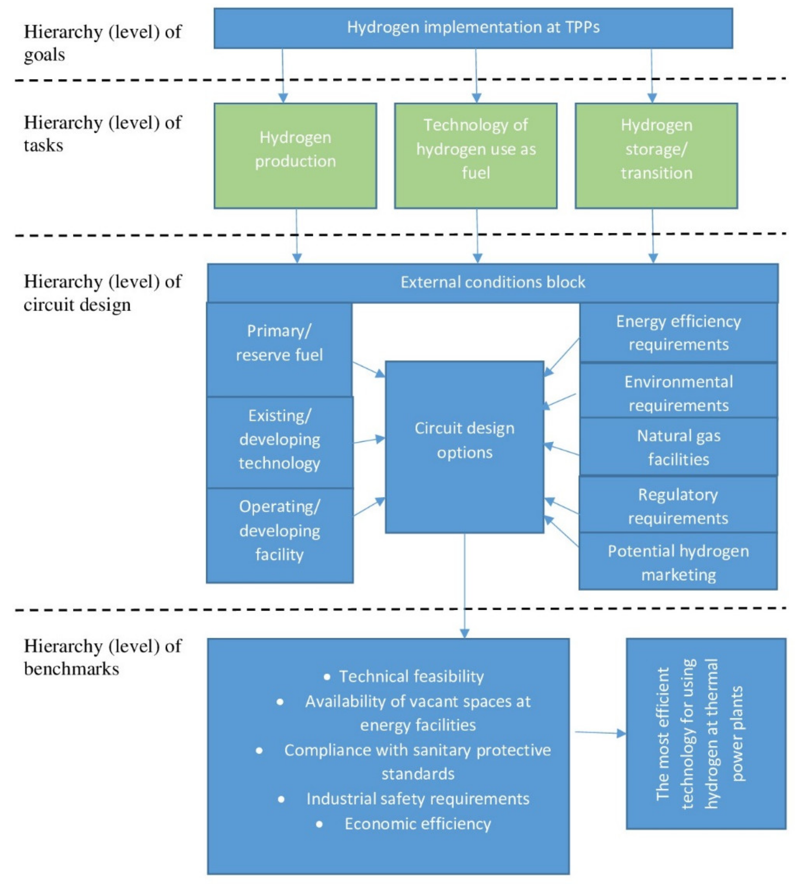
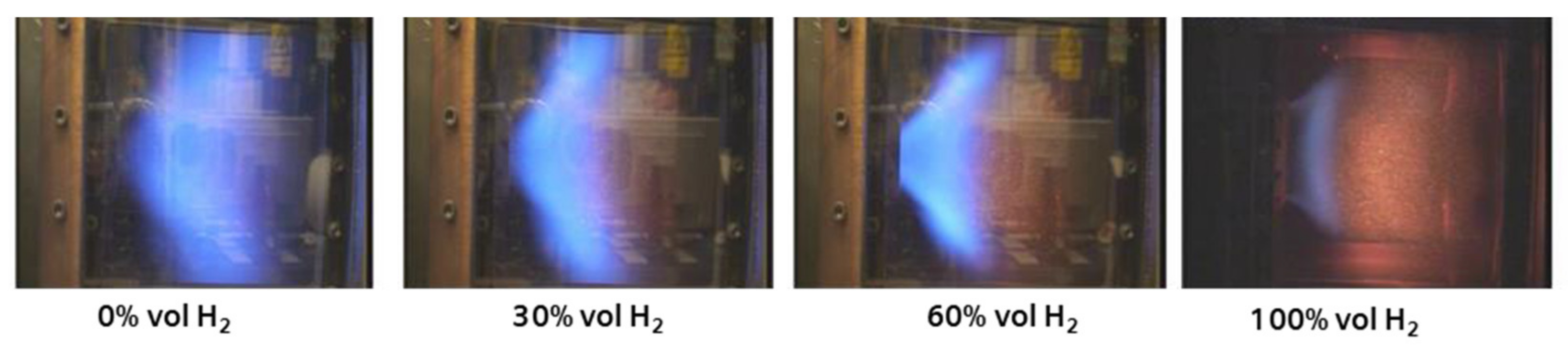

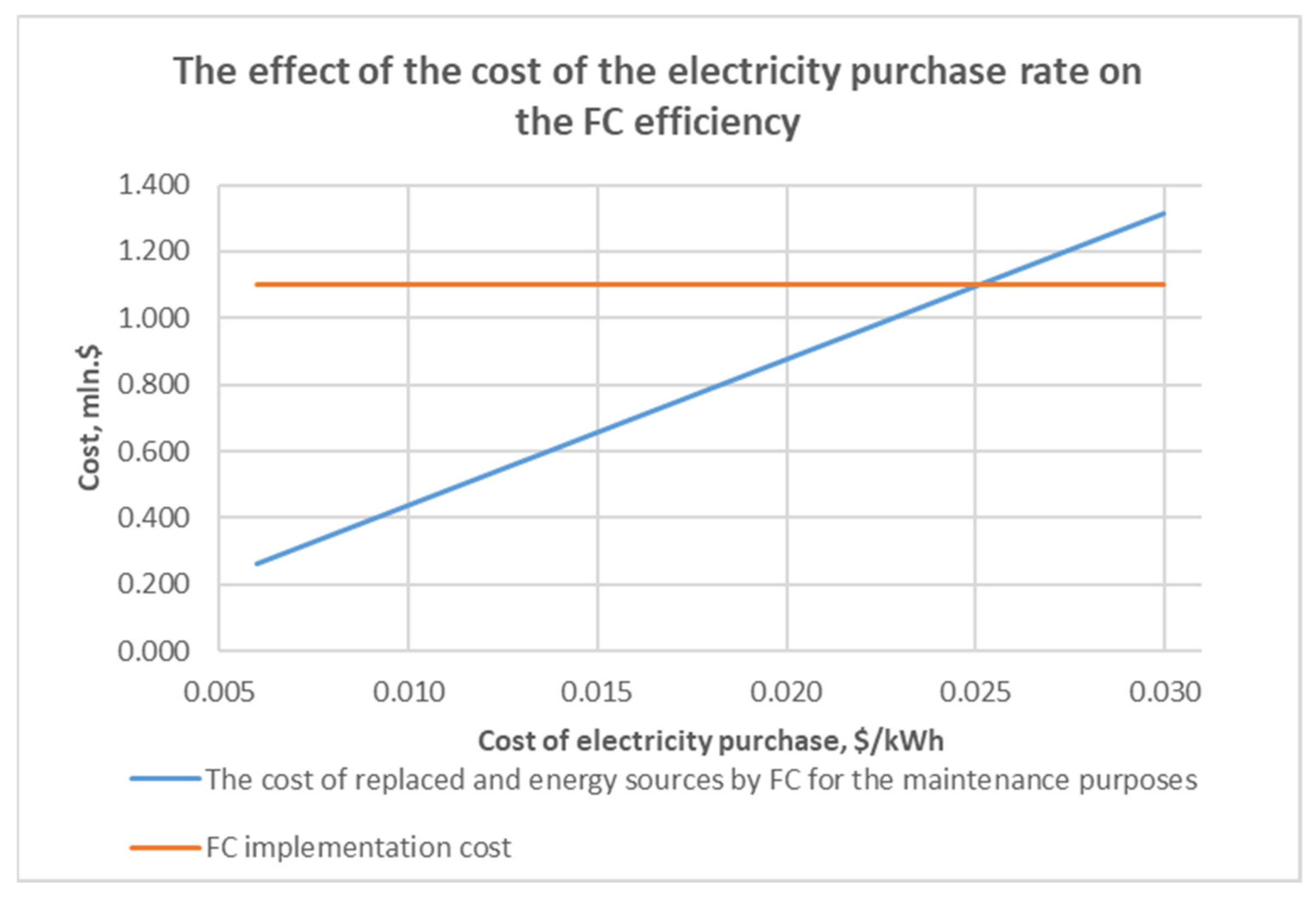
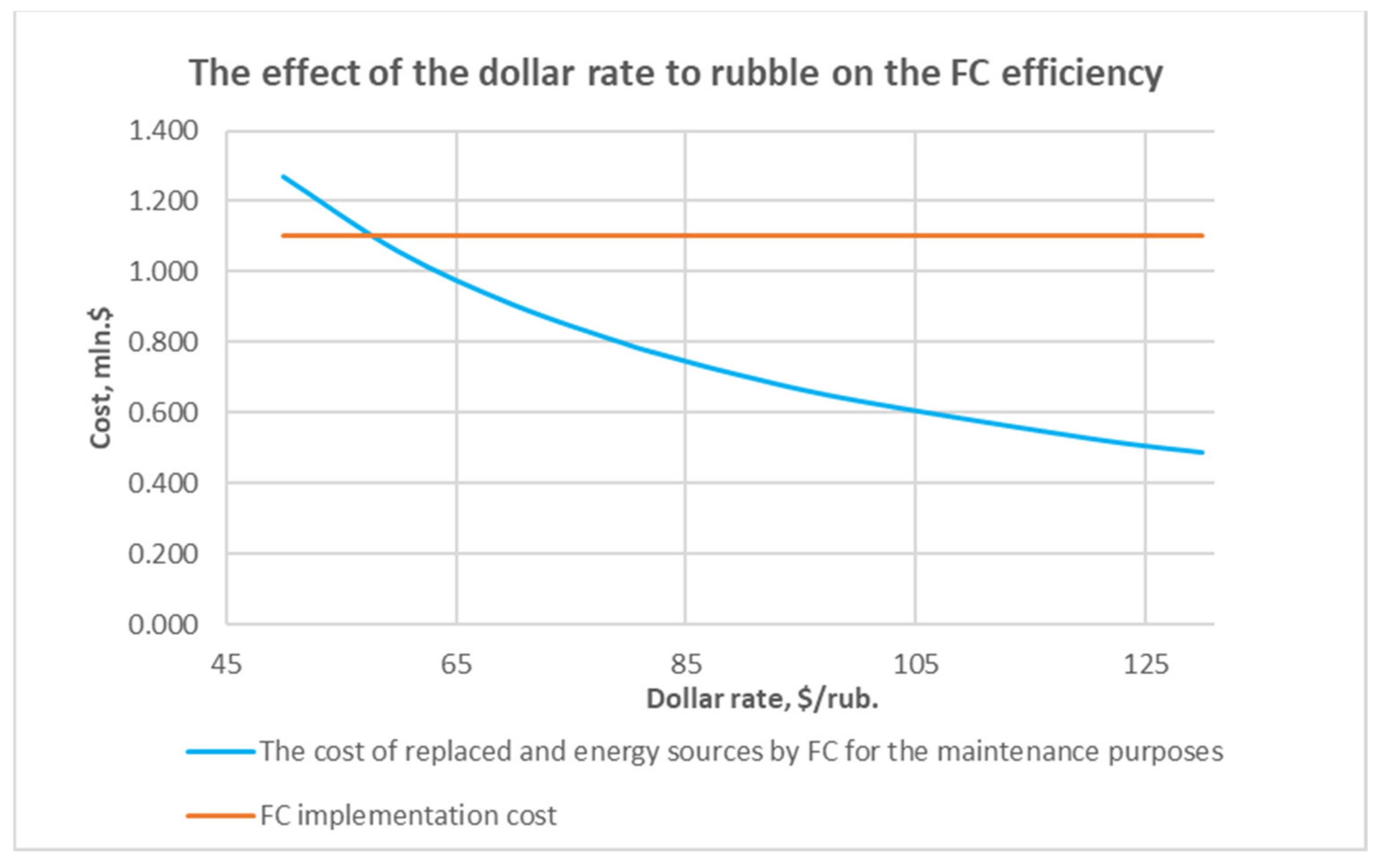
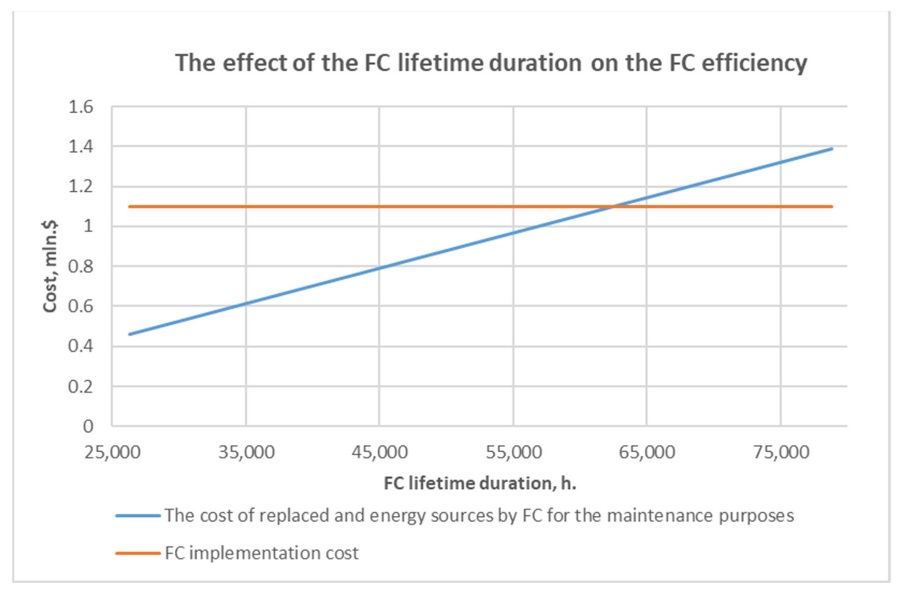
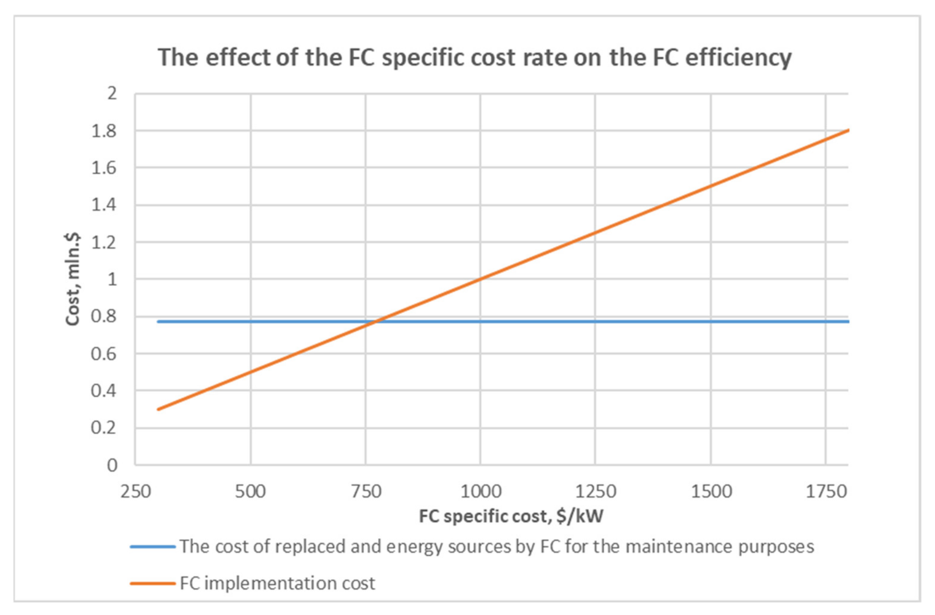
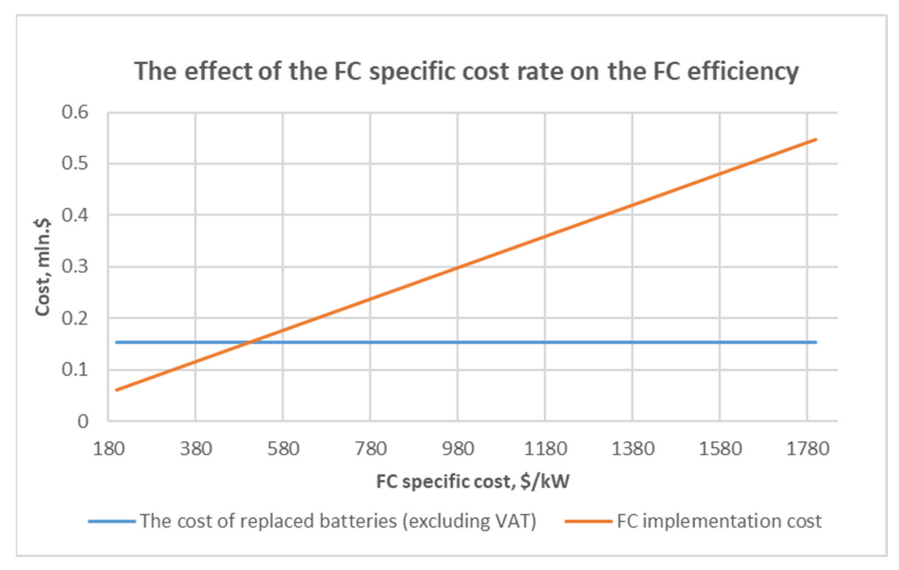
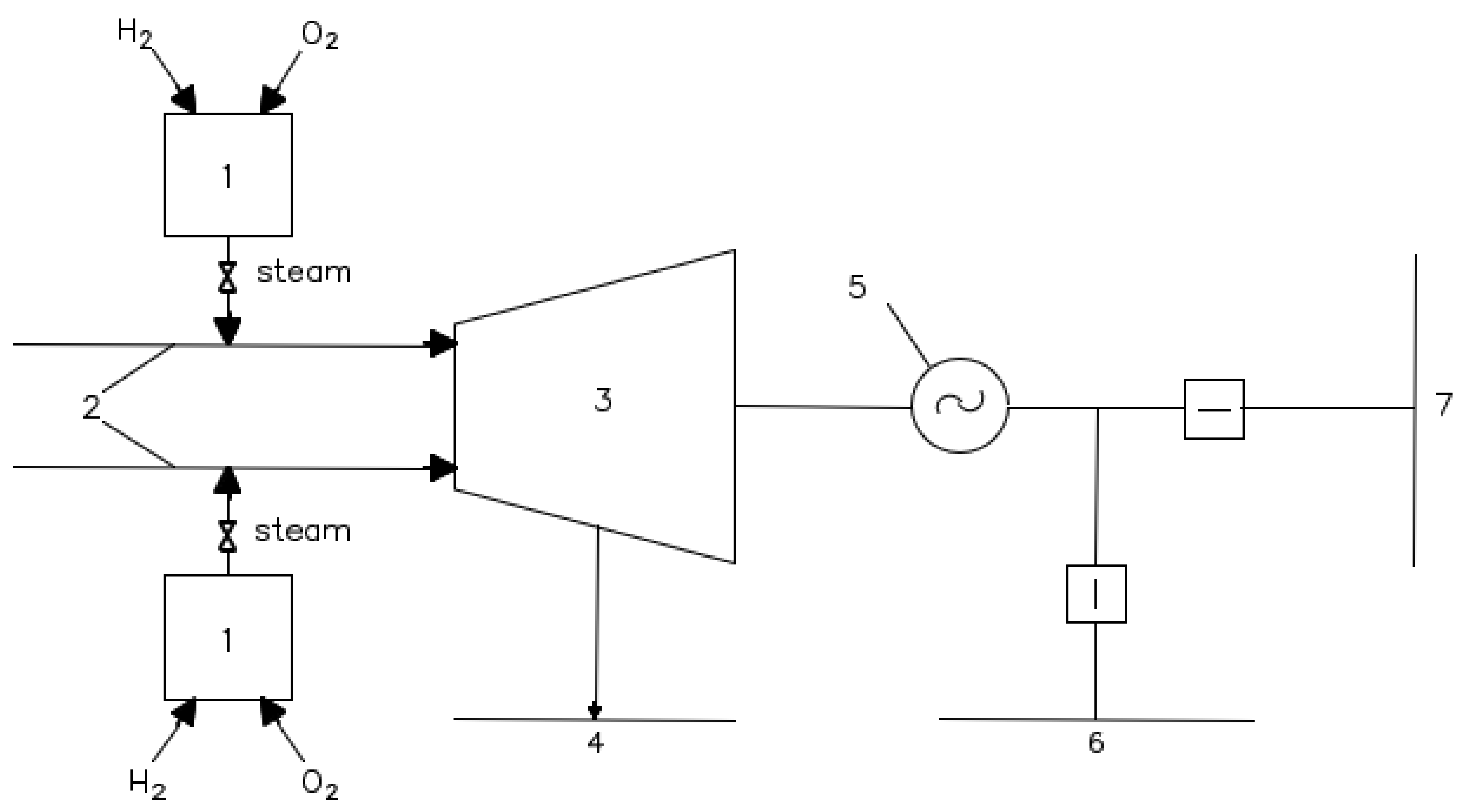
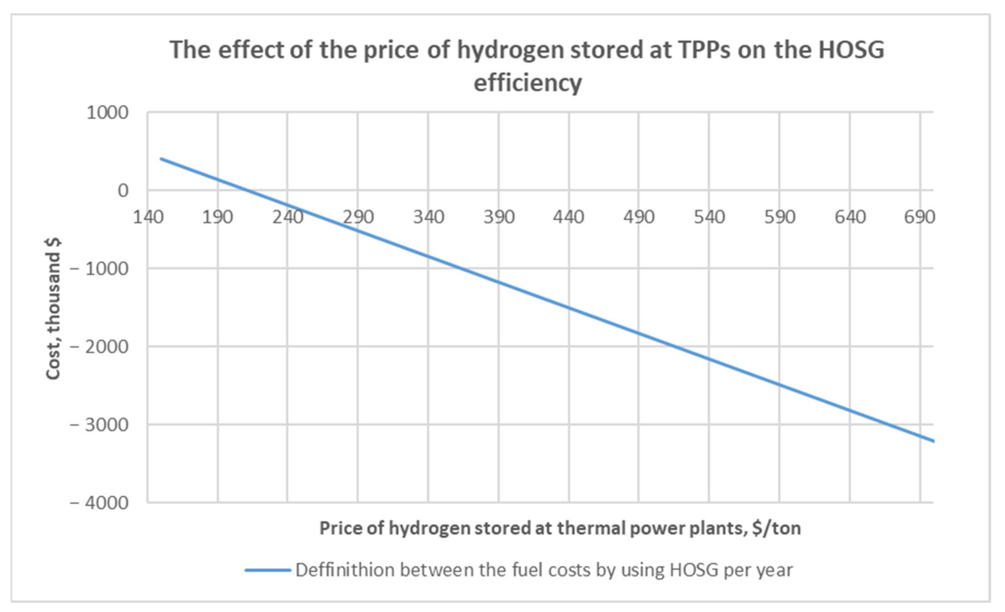
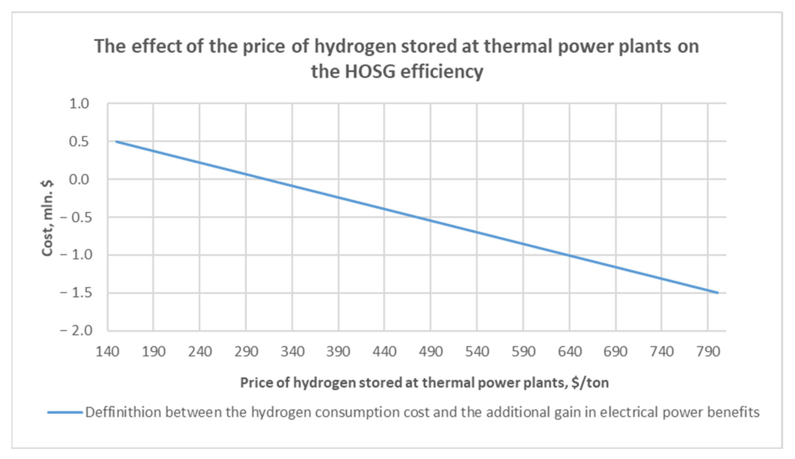
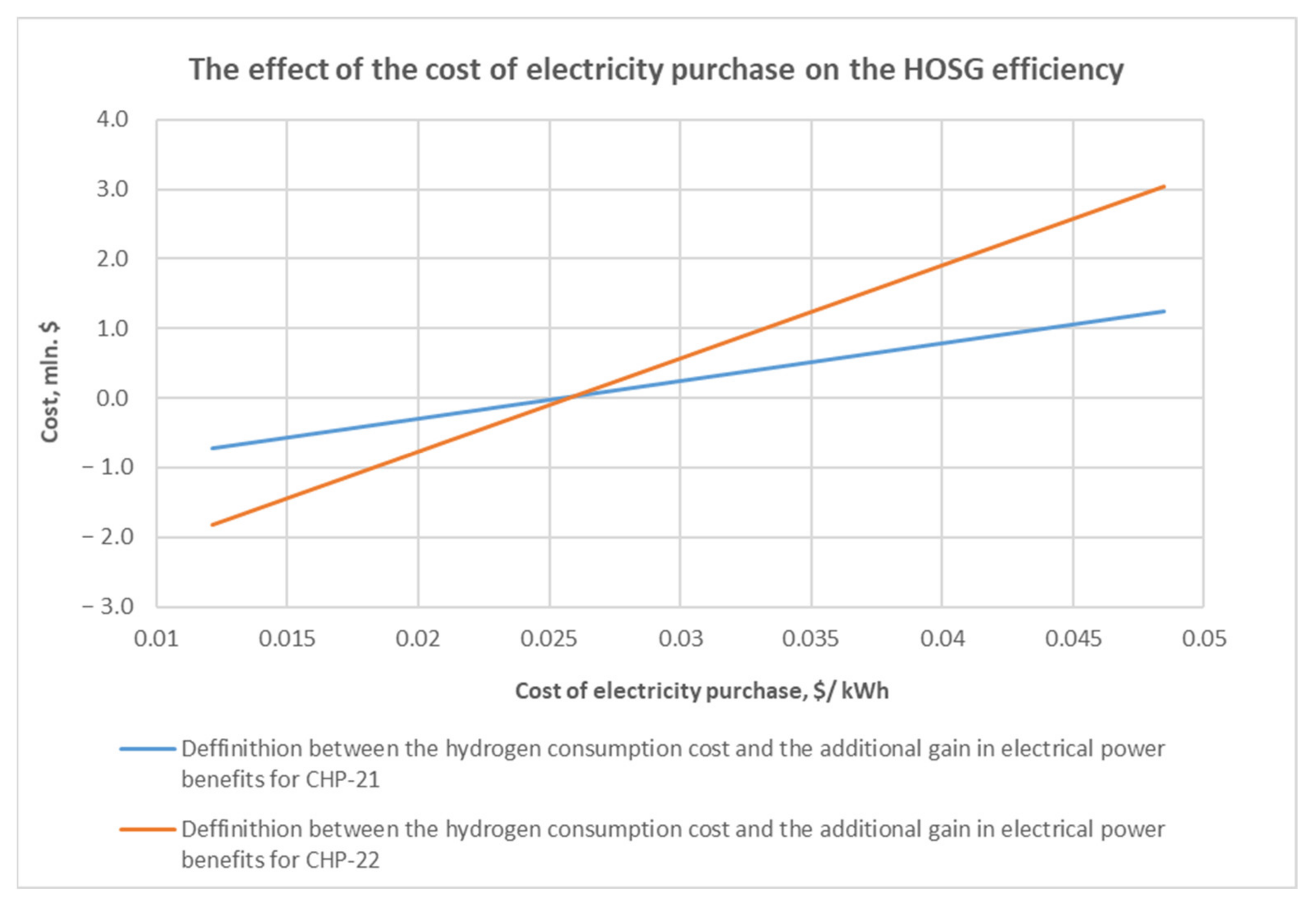


Publisher’s Note: MDPI stays neutral with regard to jurisdictional claims in published maps and institutional affiliations. |
© 2022 by the authors. Licensee MDPI, Basel, Switzerland. This article is an open access article distributed under the terms and conditions of the Creative Commons Attribution (CC BY) license (https://creativecommons.org/licenses/by/4.0/).