
Network Architecture for IEC61850-90-5 Communication: Case Study of Evaluating R-GOOSE over 5G for Communication-Based Protection


Abstract
:
1. Introduction
2. Related Work
3. Interoperability for Wide-Area Applications
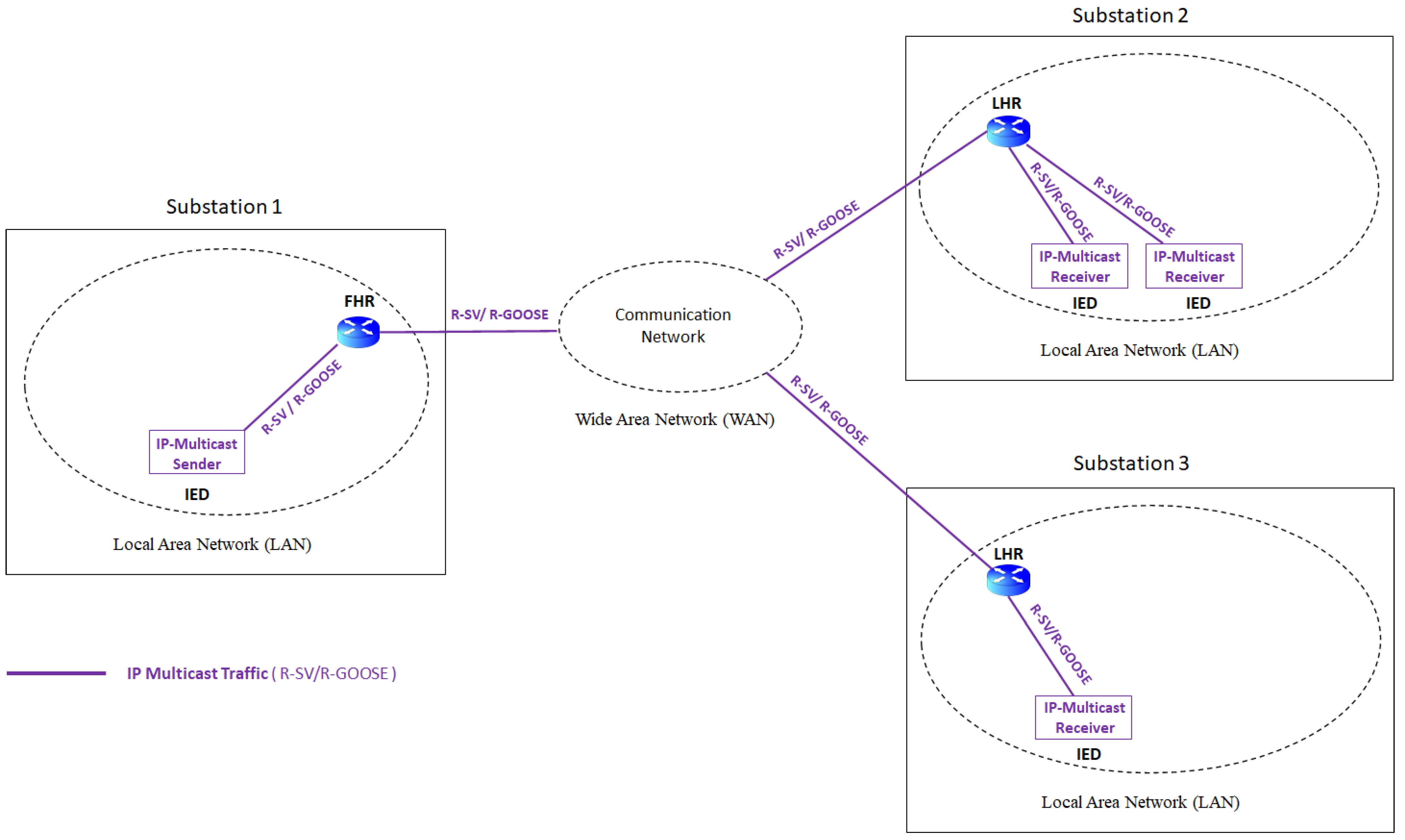
3.1. R-SV for Wide-Area Measurement
3.2. R-GOOSE for Wide-Area Protection
4. IEC61850 Multicast Communication for Wide-Area Applications
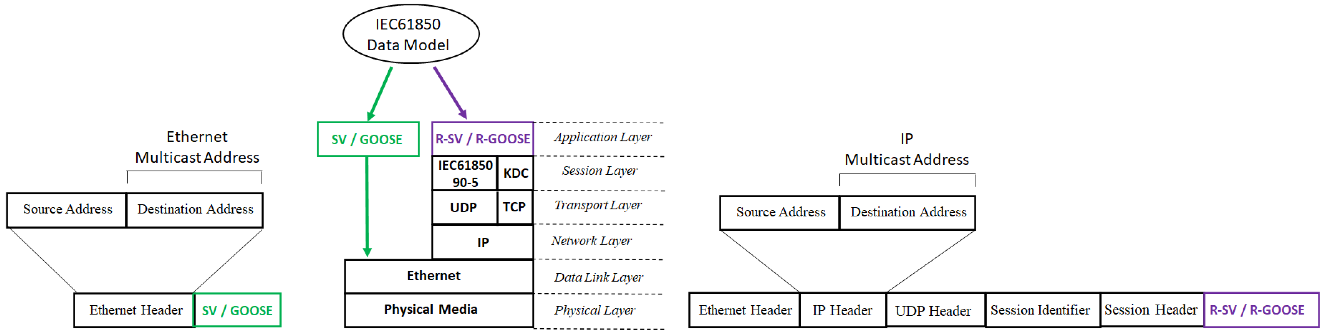
4.1. R-SV/R-GOOSE vs. SV/GOOSE
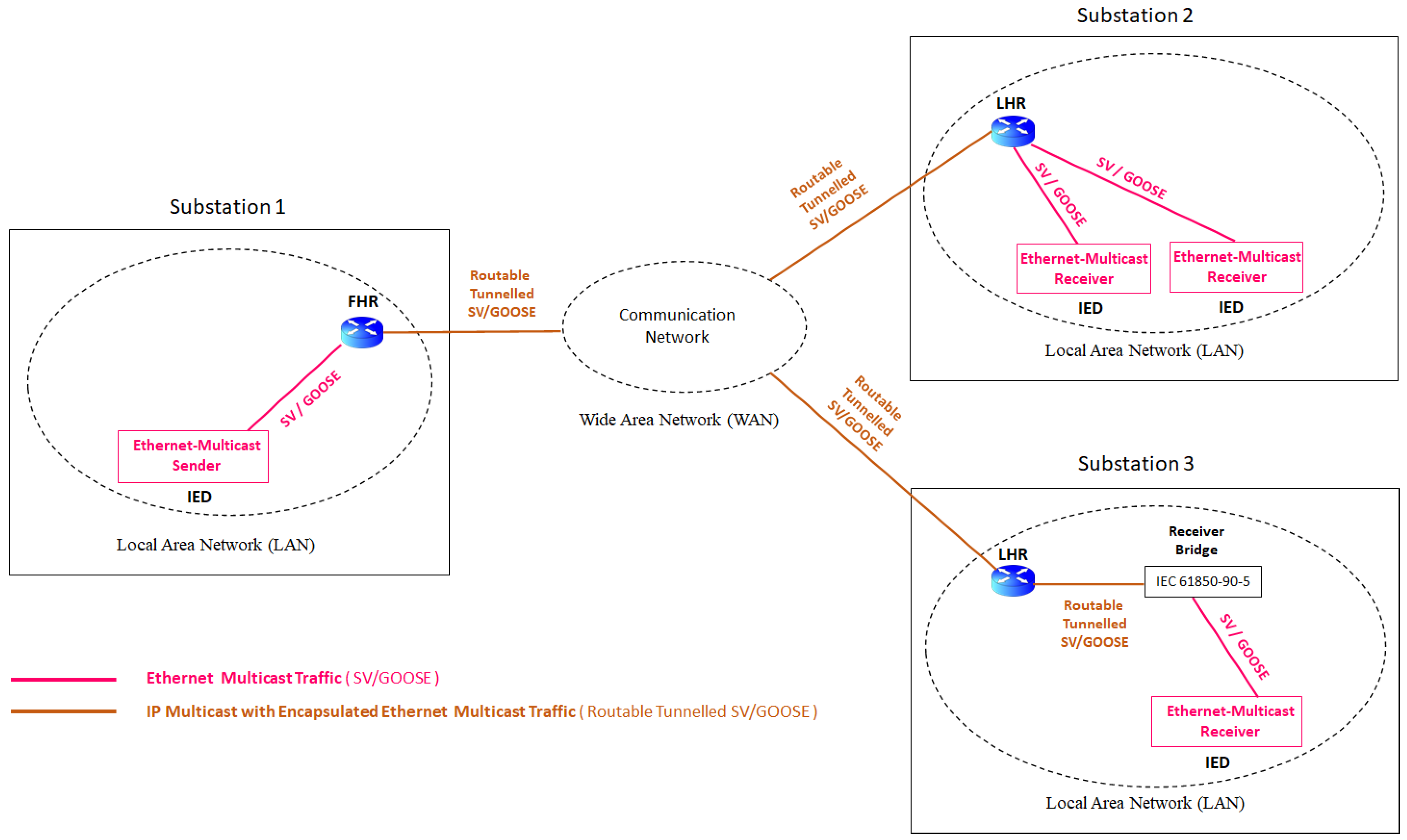
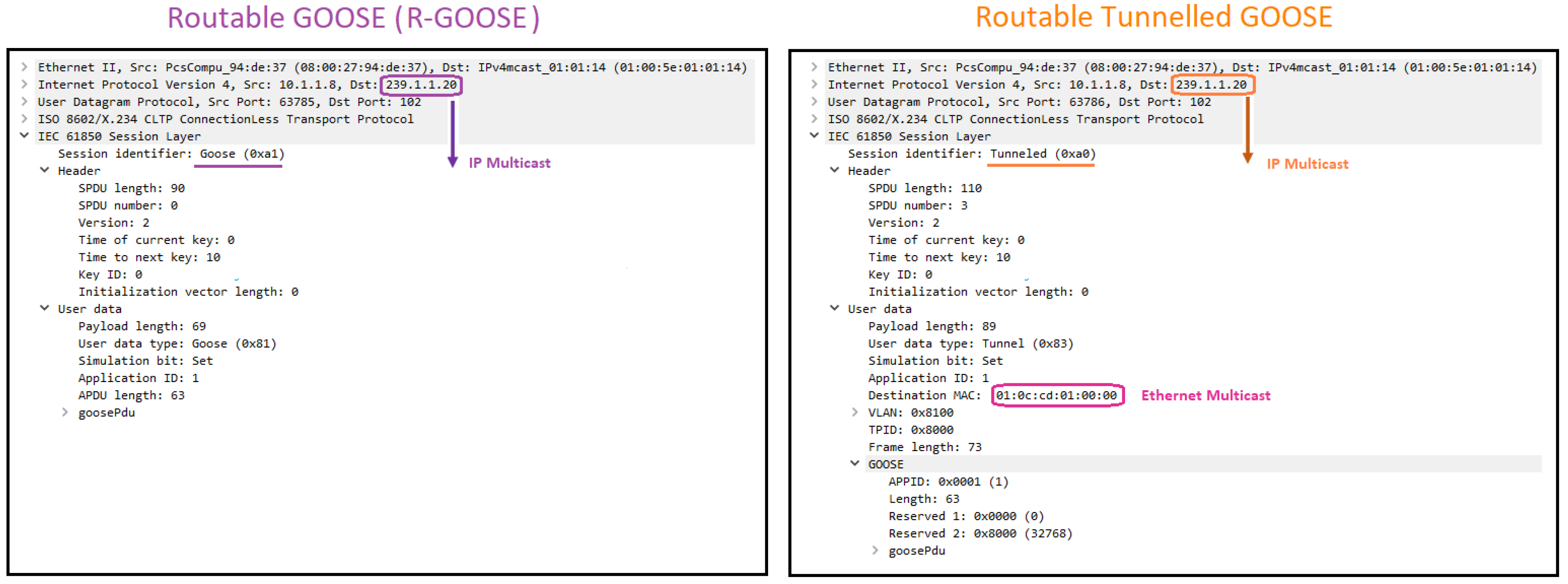
4.2. R-SV/R-GOOSE vs. Routable-Tunneled SV/GOOSE
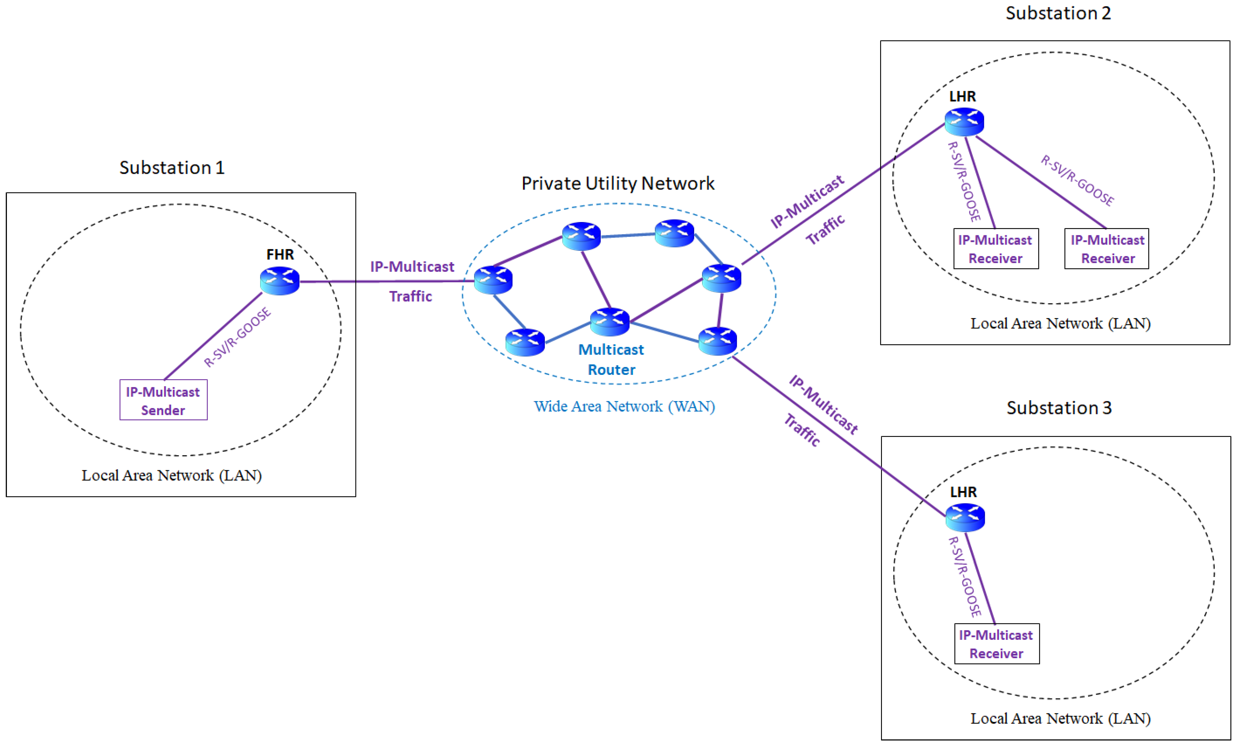
4.3. WAN Communication in Wide-Area Applications
5. Communication Dependability
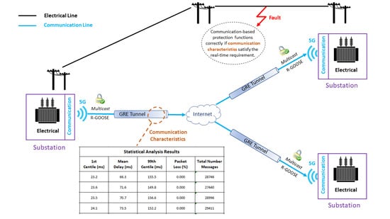
5.1. Real-Time Requirement in Wide-Area Applications
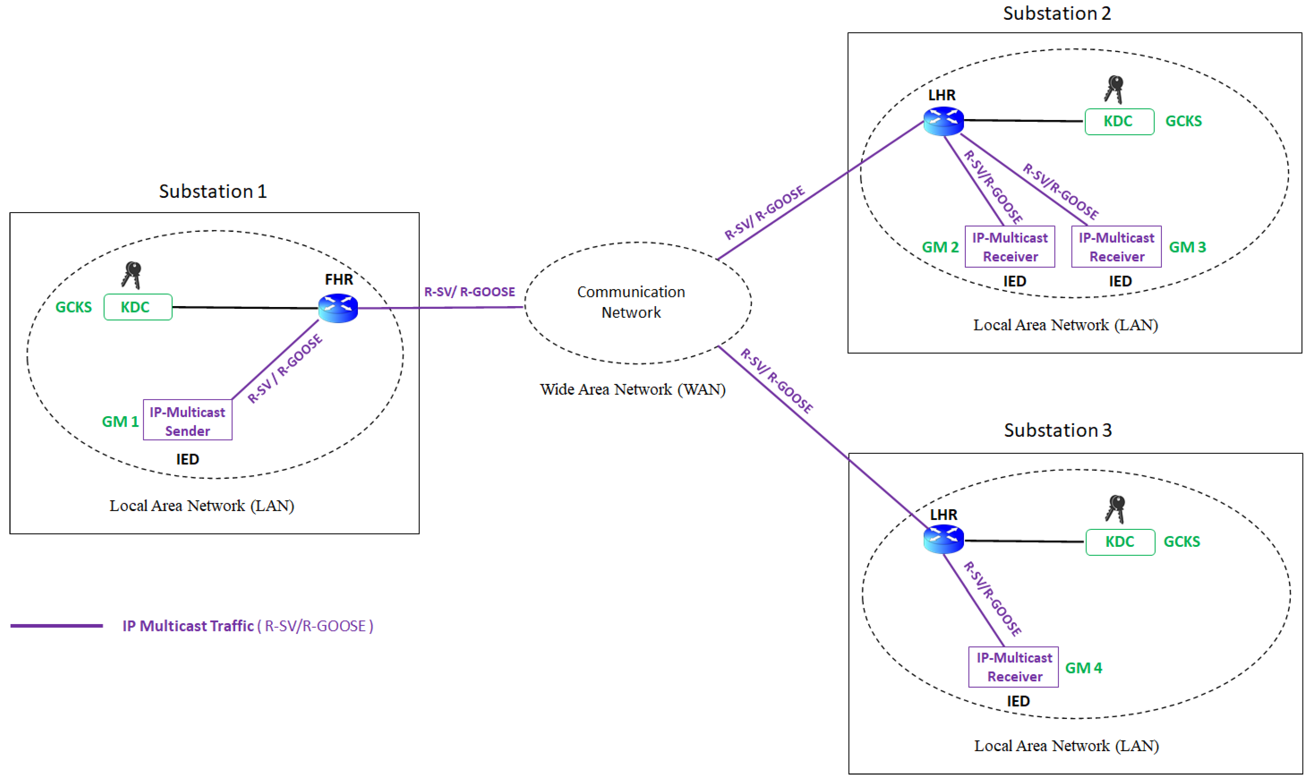
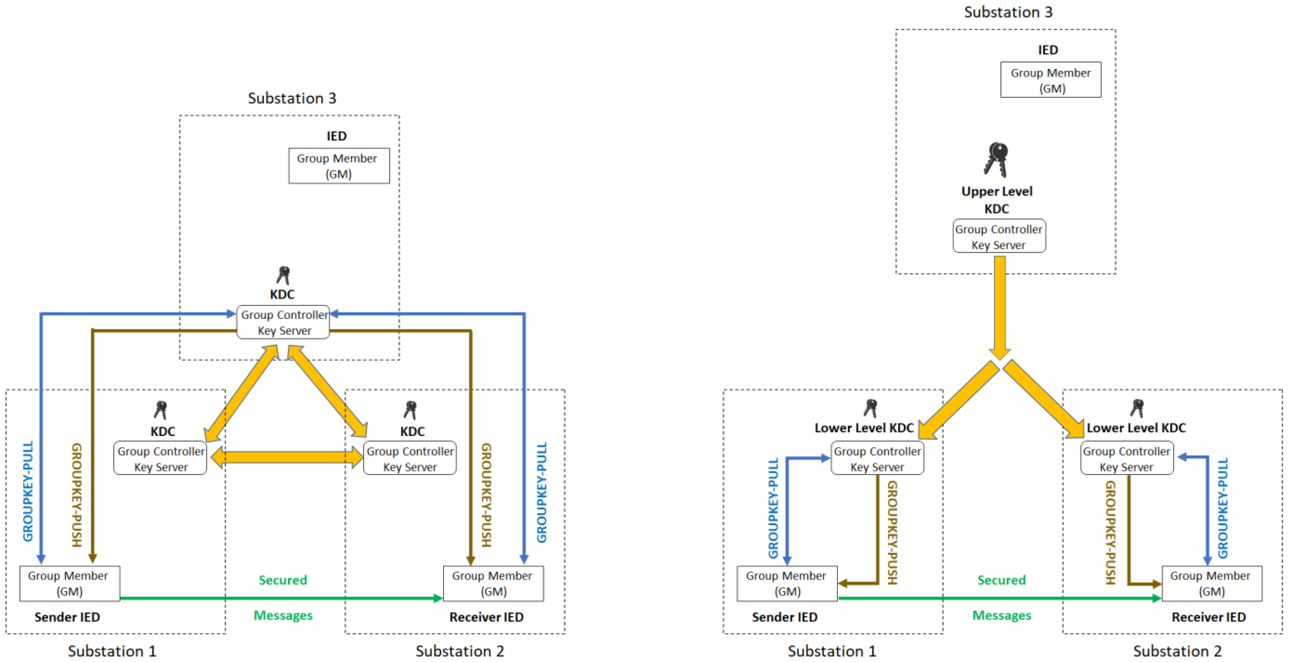
5.2. Cybersecurity for IEC61850 Multicast Communication in Wide-Area Applications
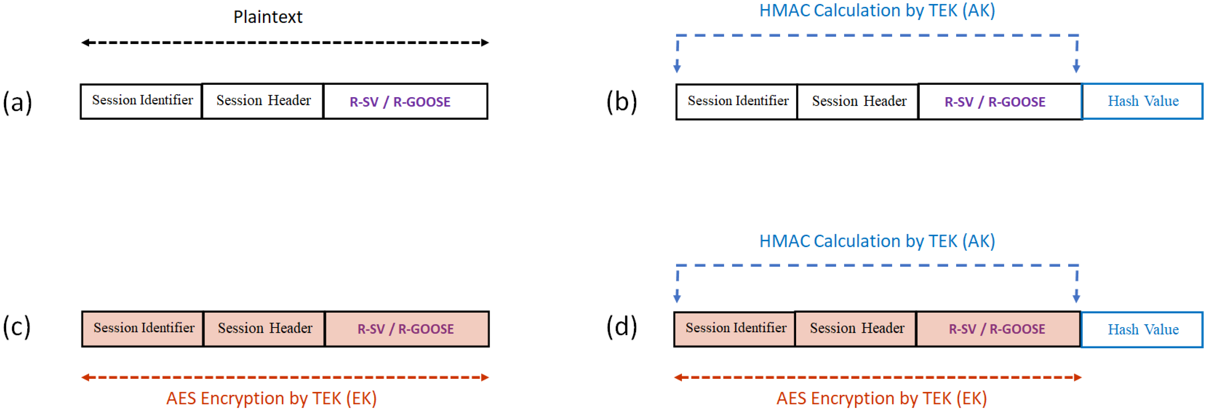
5.2.1. Secured Messages
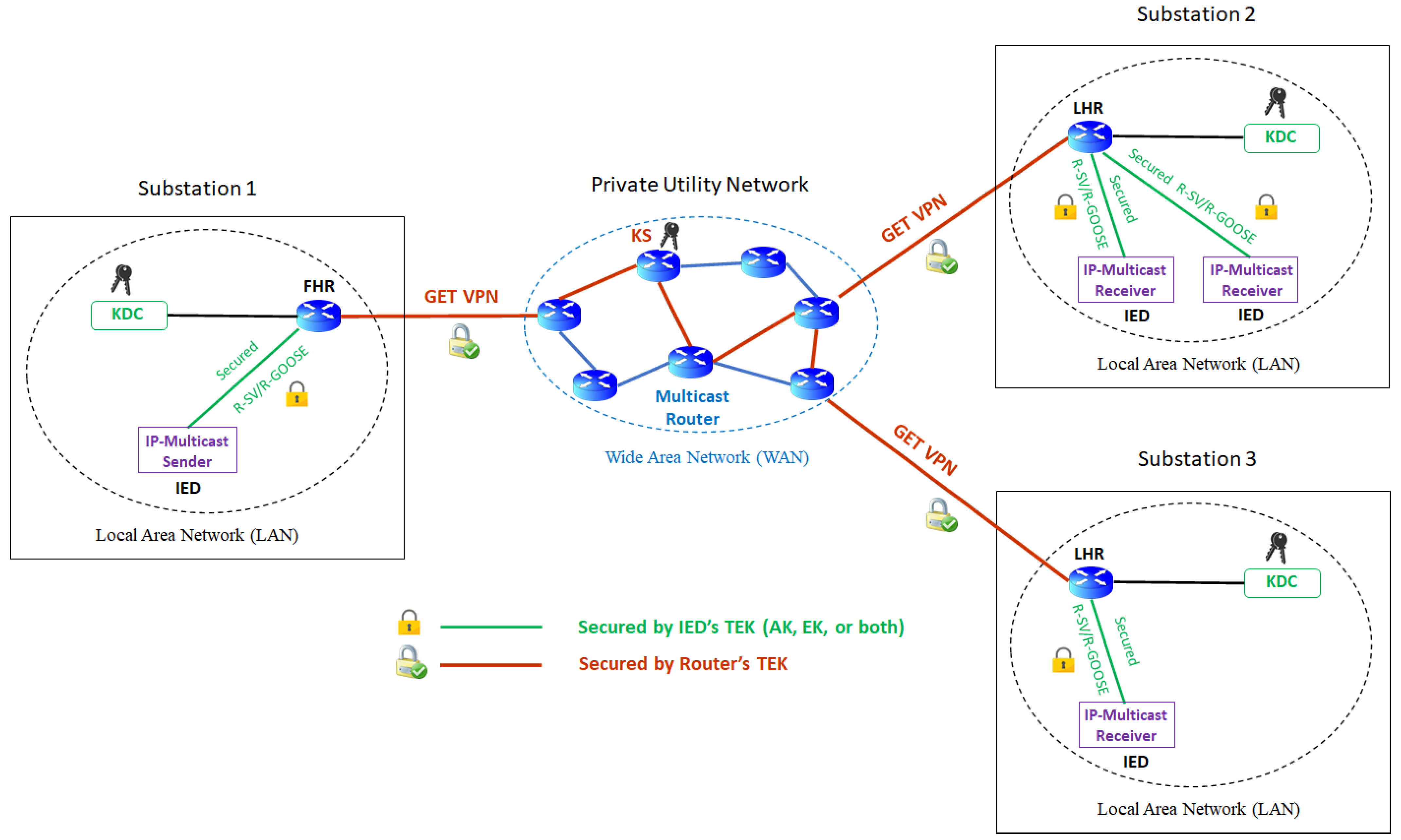
5.2.2. Secured Communication Path
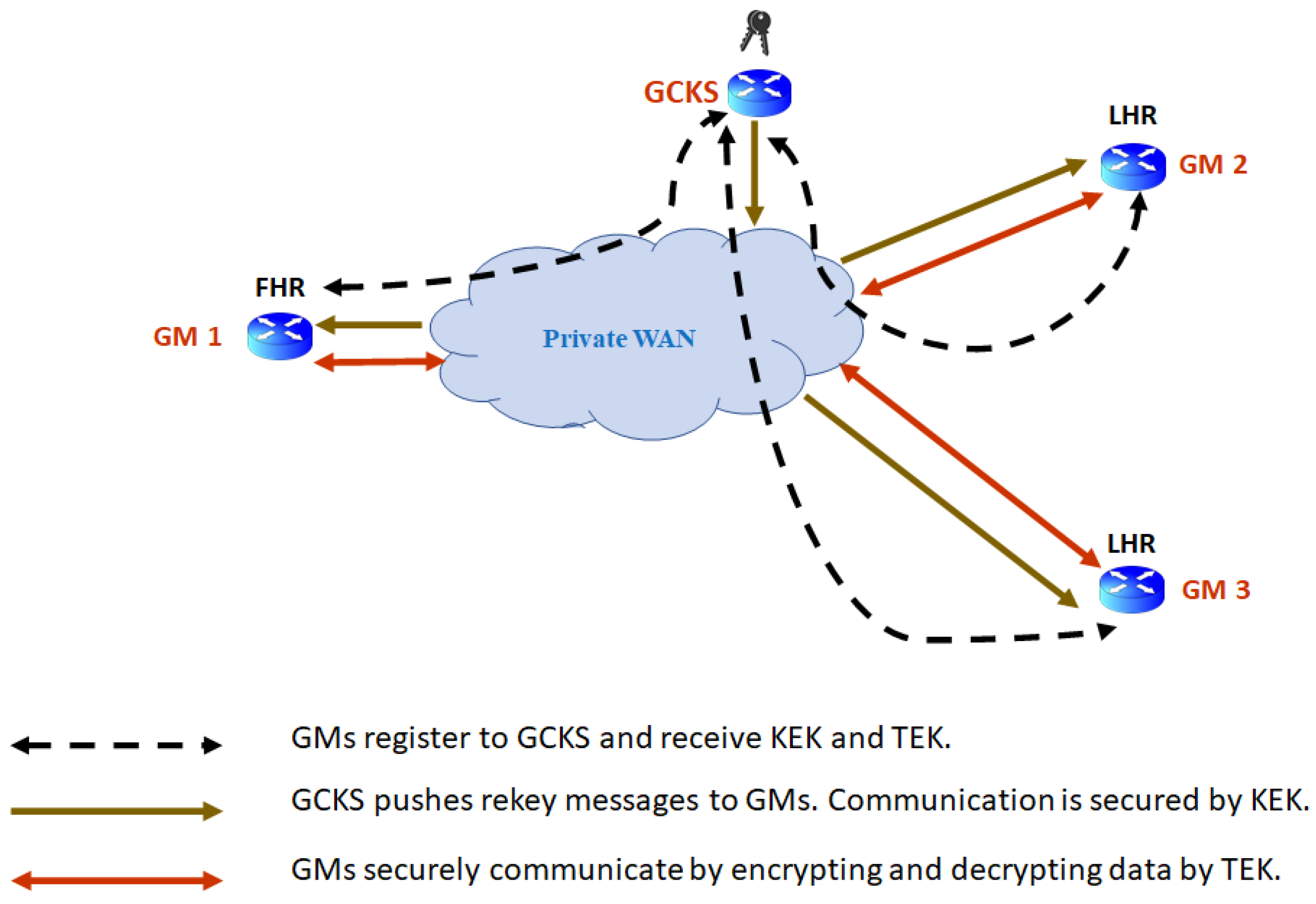
GET VPN for Private WAN
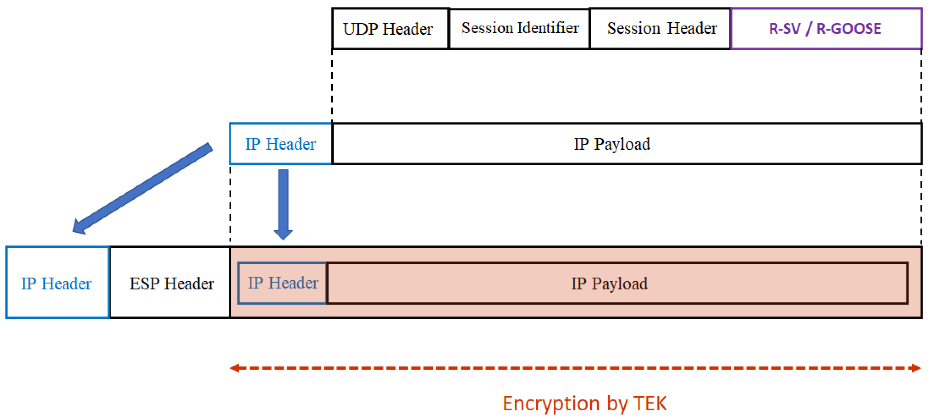
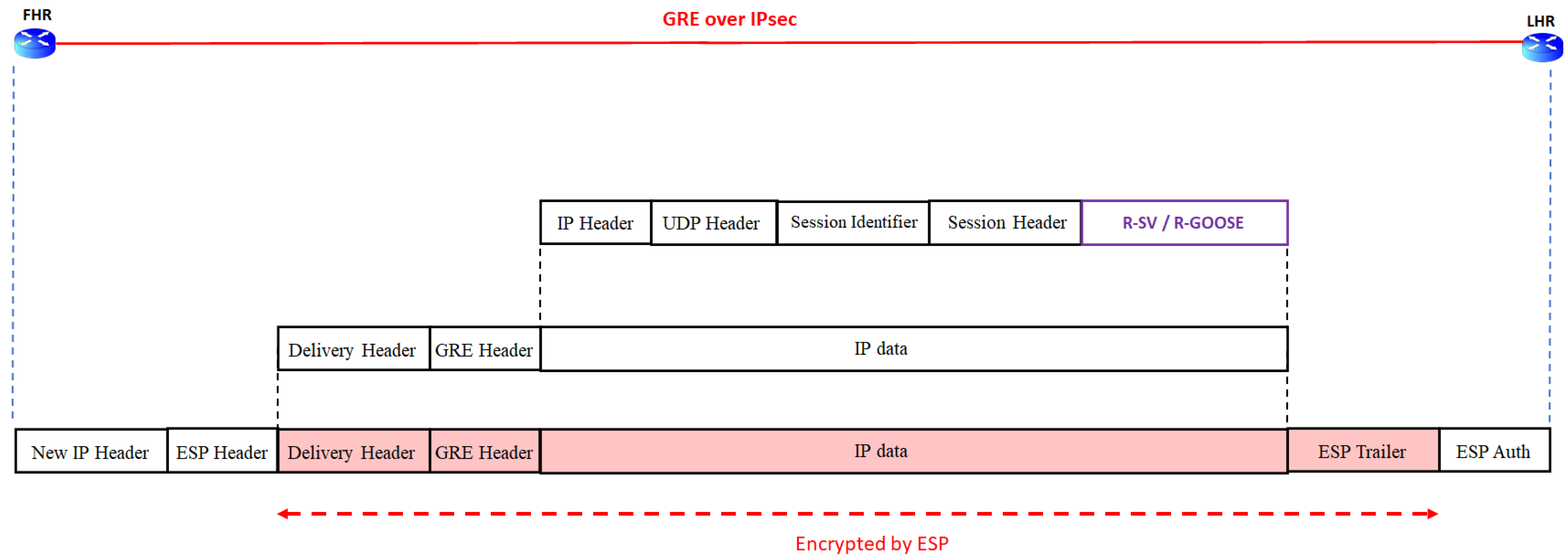
IPsec Tunnel for Public WAN
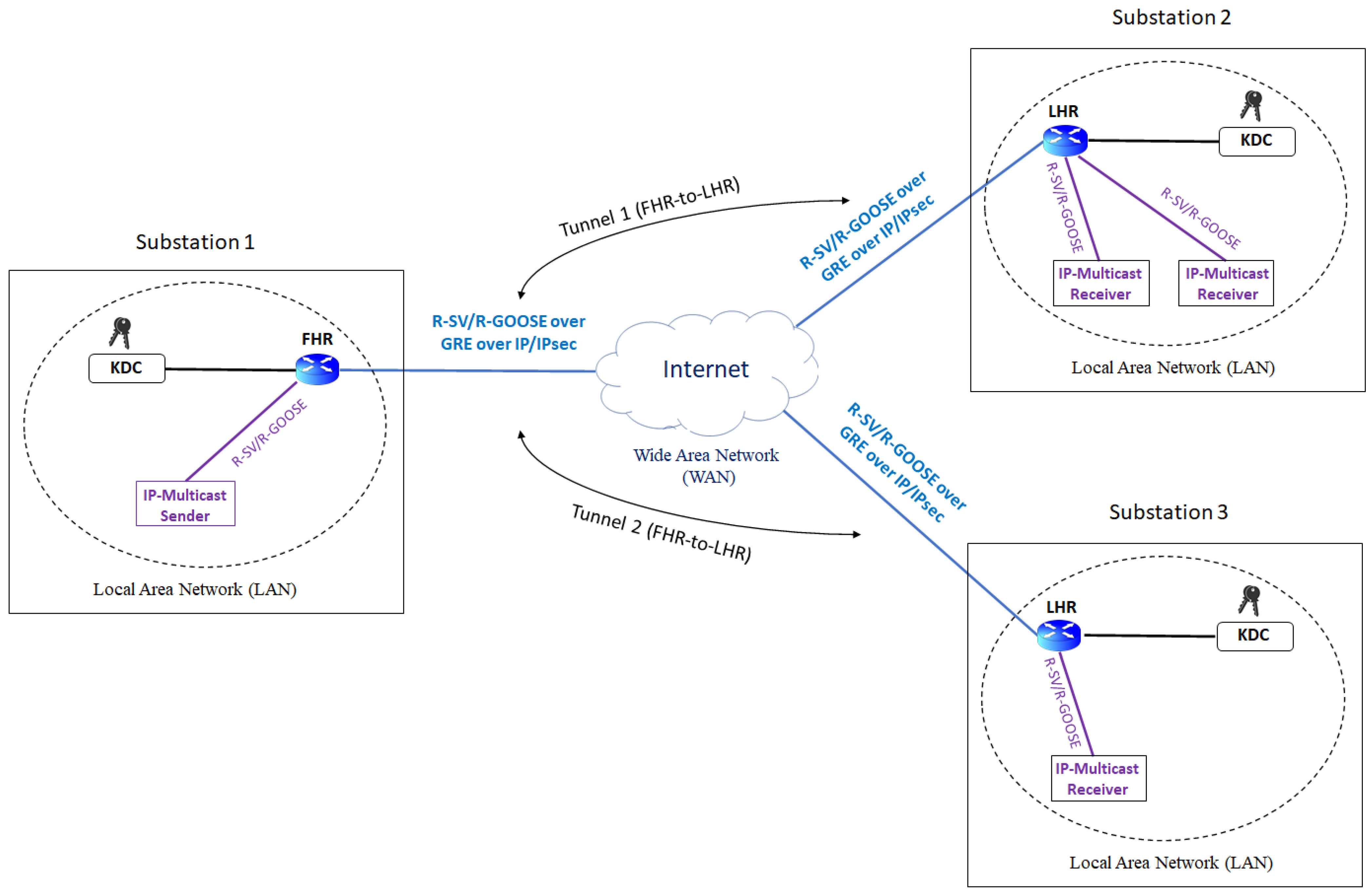
6. Network Architectures for IEC61850-90-5 Multicast over Public WAN
6.1. P2M Architecture with Seperate GRE Tunnels
6.2. P2M Architecture with mGRE in DMVPN
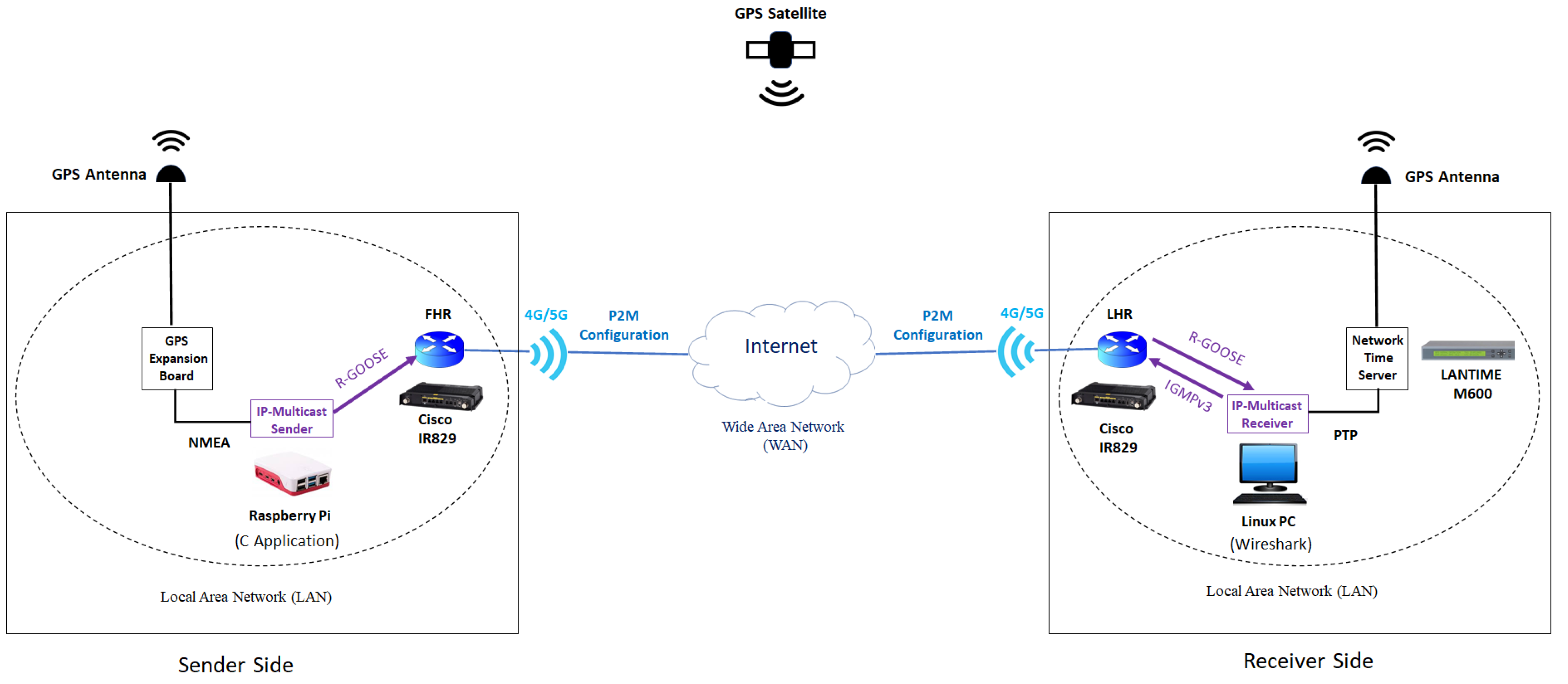
7. Performance Evaluation of Multicast R-GOOSE over Public WAN
7.1. Test Setup for Latency Measurement
7.2. Sender and Receiver Sides
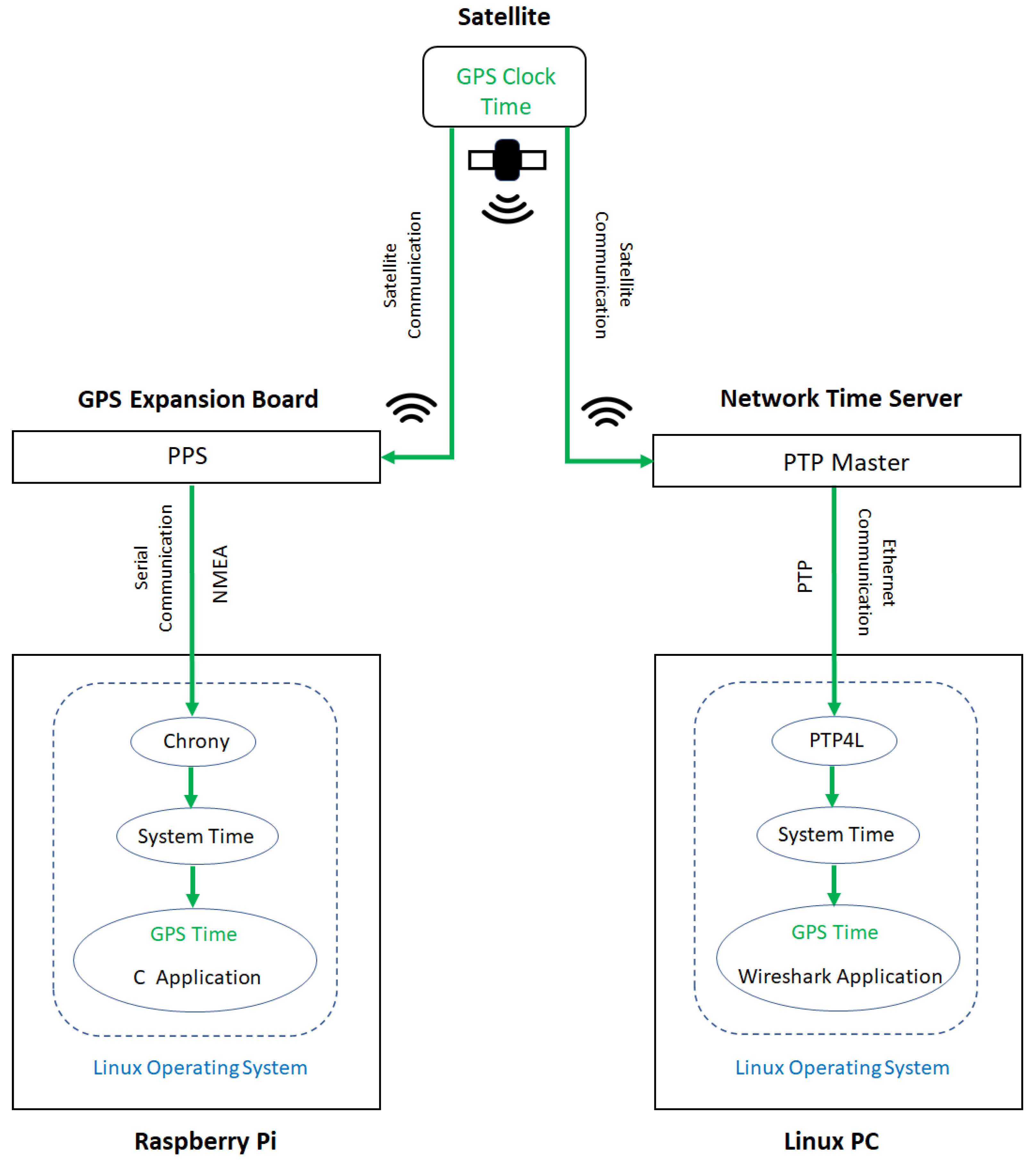
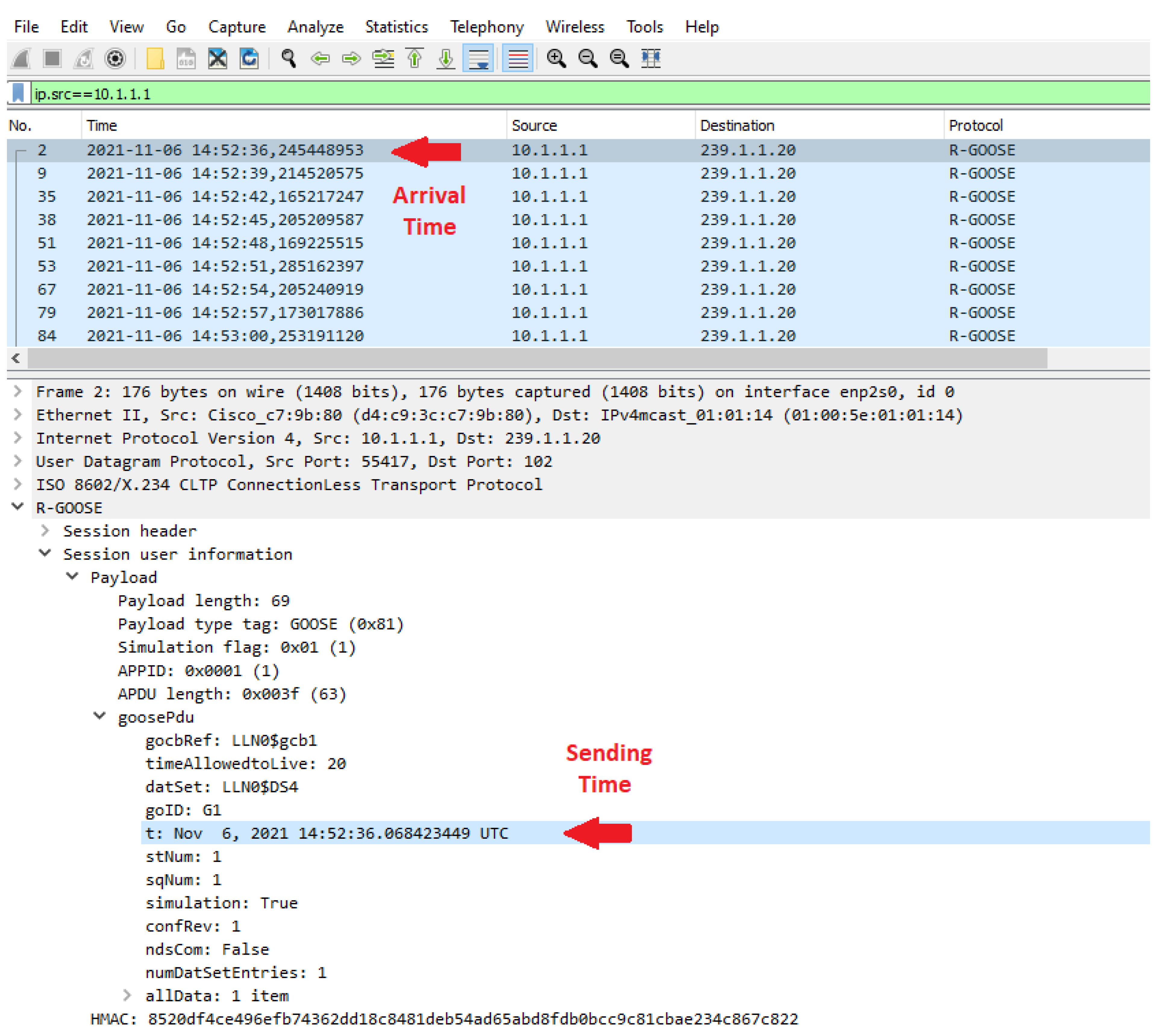
7.3. Time Synchronization
7.4. Results and Discussion
8. Conclusions
Author Contributions
Funding
Data Availability Statement
Conflicts of Interest
References
- Terzija, V.; Valverde, G.; Cai, D.; Regulski, P.; Madani, V.; Fitch, J.; Skok, S.; Begovic, M.M.; Phadke, A. Wide-area monitoring, protection, and control of future electric power networks. Proc. IEEE 2010, 99, 80–93. [Google Scholar] [CrossRef]
- IEC/TR 61850-90-5; Communication Networks and Systems for Power Utility Automation—Part 90-5: Use of IEC 61850 to Transmit Synchrophasor Information According to IEEE C37.118. Triangle MicroWorks: Raleigh, NC, USA, 2012.
- Adrah, C.M.; Yellajosula, J.R.; Kure, Ø.; Palma, D.; Heegaard, P.E. An IP multicast framework for routable sample value communication in transmission grids. J. Commun 2019, 14, 765–772. [Google Scholar] [CrossRef]
- Adrah, C.M.; Palma, D.; Kure, Ø.; Heegaard, P.E. A network design algorithm for multicast communication architectures in smart transmission grids. Electr. Power Syst. Res. 2020, 187, 106484. [Google Scholar] [CrossRef]
- Jafary, P.; Repo, S.; Koivisto, H. Security Solutions for Smart Grid Feeder Automation Data Communication. In Proceedings of the 2016 IEEE International Conference on Industrial Technology (ICIT), Taipei, Taiwan, 14–17 March 2016. [Google Scholar]
- Jafary, P.; Supponen, A.; Salmenperä, M.; Repo, S. Analyzing reliability of the communication for secure and highly available goose-based logic selectivity. J. Secur. Commun. Netw. 2019, 2019, 9682189. [Google Scholar] [CrossRef]
- Borenius, S.; Hämmäinen, H.; Lehtonen, M.; Ahokangas, P. Smart grid evolution and mobile communications—Scenarios on the Finnish power grid. Electr. Power Syst. Res. 2021, 199, 107367. [Google Scholar] [CrossRef]
- Zeinali, M.; Thompson, J.S. Implementation of Highly Accurate Testbed for Practical Evaluation of Wired and Wireless Internet based Smart Grid Communications. In Proceedings of the 2019 UK/China Emerging Technologies (UCET), IEEE, Glasgow, UK, 21–22 August 2019. [Google Scholar]
- Sobnath, D.; Rehman, I.; Nasralla, M. Smart cities to improve mobility and quality of life of the visually impaired. In Technological Trends in Improved Mobility of the Visually Impaired; Springer: Berlin/Heidelberg, Germany, 2020; pp. 3–28. [Google Scholar]
- Hovila, P.; Syväluoma, P.; Kokkoniemi-Tarkkanen, H.; Horsmanheimo, S.; Borenius, S.; Li, Z.; Uusitalo, M. 5G Networks Enabling New Smart Grid Protection Solutions. In Proceedings of the CIRED 2019 Conference, Madrid, Spain, 3–6 June 2019. [Google Scholar]
- Hovila, P.; Kokkoniemi-Tarkkanen, H.; Horsmanheimo, S.; Raussi, P.; Borenius, S.; Ahola, K. Cellular Networks Providing Distribution Grid Communications Platform. In Proceedings of the CIRED 2021—The 26th International Conference and Exhibition on Electricity Distribution, Online Conference, 20–23 September 2021. [Google Scholar]
- Rivas, A.E.L.; Abrao, T. Faults in smart grid systems: Monitoring, detection and classification. Electr. Power Syst. Res. 2021, 189, 106602. [Google Scholar] [CrossRef]
- Gutierrez-Rojas, D.; Nardelli, P.H.J.; Mendes, G.; Popovski, P. Review of the state of the art on adaptive protection for microgrids based on communications. IEEE Trans. Ind. Informat 2020, 17, 1539–1552. [Google Scholar] [CrossRef]
- Nguyen, V.G.; Grinnemo, K.J.; Cheng, J.; Taheri, J.; Brunstrom, A. On the Use of a Virtualized 5G Core for Time Critical Communication in Smart Grid. In Proceedings of the 8th IEEE International Conference on Mobile Cloud Computing, Services, and Engineering (MobileCloud), Oxford, UK, 3–6 August 2020. [Google Scholar]
- Nguyen, V.G.; Grinnemo, K.J.; Taheri, J.; Brunstrom, A. A Deployable Containerized 5G Core Solution for Time Critical Communication in Smart Grid. In Proceedings of the 23rd Conference on Innovation in Clouds, Internet and Networks and Workshops (ICIN), Paris, France, 24–27 February 2020. [Google Scholar]
- The NTP Stratum Model. Available online: https://orolia.com/manuals/SS/Content/_Global/Topics/NTP/NTP_Stratums.htm (accessed on 13 May 2022).
- Zhu, K.; Chenine, M.; Nordstrom, L. ICT architecture impact on wide area monitoring and control systems’ reliability. IEEE Trans. Power Deliv. 2011, 26, 2801–2808. [Google Scholar] [CrossRef]
- Wang, Y.; Gamage, T.T.; Hauser, C.H. Security implications of transport layer protocols in power grid synchrophasor data communication. IEEE Trans. Smart Grid 2015, 7, 807–816. [Google Scholar] [CrossRef]
- Khan, R.; Mclaughlin, K.; Laverty, D.; Sezer, S. Design and implementation of security gateway for synchrophasor based real-time control and monitoring in smart grid. IEEE Access 2017, 5, 11626–11644. [Google Scholar] [CrossRef] [Green Version]
- Firouzi, S.R.; Vanfretti, L.; Ruiz-Alvarez, A.; Mahmood, F.; Hooshyar, H.; Cairo, I. An IEC 61850-90-5 Gateway for IEEE C37. 118.2 Synchrophasor Data Transfer. In Proceedings of the 2016 IEEE Power and Energy Society General Meeting (PESGM), Boston, MA, USA, 17–21 July 2016. [Google Scholar]
- Ruuth, K.; Supponen, A.; Repo, S.; Rosenørn, K.R.; Douglass, P.; Møller, M. Practical Implementation of Optimal Voltage Control in Distribution Network–System Verification, Testing and Safety Precautions. In Proceedings of the 2020 IEEE PES Innovative Smart Grid Technologies Europe (ISGT-Europe), The Hague, The Netherlands, 26–28 October 2020. [Google Scholar]
- Eissa, M.M. Challenges and novel solution for wide-area protection due to renewable sources integration into smart grid: An extensive review. IET Renew. Power Gener. 2018, 12, 1843–1853. [Google Scholar] [CrossRef]
- An, W.; Zhao, M.Y.; Li, J.S.; Zhou, H.Y.; Chen, Z.H.; Yu, J.; Huang, W.F.; Li, L.; Chen, S.J. Application of Wide Area Monitoring Protection and Control in an Electricity Distribution Network. In Proceedings of the 12th IET International Conference on Developments in Power System Protection (DPSP 2014), Copenhagen, Denmark, 31 March–3 April 2014. [Google Scholar]
- Ledesma, P.; Jafary, P.; Repo, S.; Álvarez, A.; Ramos, F.; Della Giustina, D.; Dedè, A. Event-based simulation of a decentralized protection system based on secured GOOSE messages. Energies 2020, 13, 3250. [Google Scholar] [CrossRef]
- Eriksson, M.; Armendariz, M.; Vasilenko, O.O.; Saleem, A.; Nordström, L. Multiagent-based distribution automation solution for self-healing grids. IEEE Trans. Ind. Electron 2014, 62, 2620–2628. [Google Scholar] [CrossRef]
- Jafary, P.; Raipala, O.; Repo, S.; Salmenperä, M.; Seppälä, J.; Koivisto, H.; Horsmanheimo, S.; Kokkoniemi-Tarkkanen, H.; Tuomimäki, L.; Alvarez, A.; et al. Secure Layer 2 Tunneling over IP for GOOSE-based Logic Selectivity. In Proceedings of the 2017 IEEE International Conference on Industrial Technology (ICIT), Toronto, ON, Canada, 22–25 March 2017. [Google Scholar]
- Raipala, O.; Repo, S.; Järventausta, P. A Communication based Protection System for Solving DG related Protection Challenges. In Proceedings of the CIRED 2015, Lyon, France, 15–18 June 2015. [Google Scholar]
- De Oliveira, C.H.R.; Bowen, A.P. IEC 61850 Goose Message over Wan. In Proceedings of the International Conference on Wireless Networks (ICWN), The Steering Committee of The World Congress in Computer Science, Computer Engineering and Applied Computing (WorldComp), Las Vegas, NV, USA, 22–25 July 2013. [Google Scholar]
- Wen, J.; Hammond, C.; Udren, E.A. Wide-area Ethernet Network Configuration for System Protection Messaging. In Proceedings of the 2012 65th Annual Conference for Protective Relay Engineers, IEEE, College Station, TX, USA, 2–5 April 2012. [Google Scholar]
- Kanabar, M.; Cioraca, A.; Johnson, A. Wide Area Protection & Control Using High-speed and Secured Routable Goose mechanism. In Proceedings of the 2016 69th Annual Conference for Protective Relay Engineers (CPRE), IEEE, College Station, TX, USA, 4–7 April 2016. [Google Scholar]
- Seewald, M. Building an architecture based on IP-Multicast for Large Phasor Measurement Unit (PMU) Networks. In Proceedings of the 2013 IEEE PES Innovative Smart Grid Technologies Conference (ISGT), Washington, DC, USA, 24–27 February 2013. [Google Scholar]
- IEC61850 Avenue Software Tools. Available online: https://www.infotech.pl/products/iec-61850 (accessed on 13 May 2022).
- Configuring IP-Multicast Routing. Available online: https://www.cisco.com/c/en/us/td/docs/switches/metro/me3600x_3800x/software/release/12-2_52_ey/configuration/guide/swmcast.html (accessed on 13 May 2022).
- Generic Routing Encapsulation (GRE). Available online: https://datatracker.ietf.org/doc/html/rfc1701 (accessed on 13 May 2022).
- Zseby, T.; Fabini, J. Security challenges for wide area monitoring in smart grids. E & I Elektrotechnik und Informationstechnik 2014, 131, 105–111. [Google Scholar]
- Ashok, A.; Govindarasu, M.; Wang, J. Cyber-physical attack-resilient wide-area monitoring, protection, and control for the power grid. Proc. IEEE 2017, 105, 1389–1407. [Google Scholar] [CrossRef]
- The Group Domain of Interpretation. Available online: https://tools.ietf.org/html/rfc6407 (accessed on 13 May 2022).
- Internet Security Association and Key Management Protocol (ISAKMP). Available online: https://tools.ietf.org/html/rfc2408 (accessed on 13 May 2022).
- IEC 62351-9; Power Systems Management and Associated Information Exchange—Data and Communications Security—Part 9: Cyber Security Key Management for Power System Equipment. International Electrotechnical Commission: Geneva, Switzerland, 2017.
- Group Domain of Interpretation (GDOI). Protocol Support for IEC 62351 Security Services, RFC 8052. Available online: https://datatracker.ietf.org/doc/html/rfc8052 (accessed on 13 May 2022).
- Group Encrypted Transport VPN (GETVPN) Design and Implementation Guide. Available online: https://www.cisco.com/c/dam/en/us/products/collateral/security/group-encrypted-transport-vpn/GETVPN_DIG_version_2_0_External.pdf (accessed on 13 May 2022).
- Security Architecture for the Internet Protocol. Available online: https://tools.ietf.org/html/rfc2401 (accessed on 13 May 2022).
- Introduction to DMVPN. Available online: https://networklessons.com/cisco/ccie-routing-switching/introduction-to-dmvpn#Multipoint_GRE (accessed on 13 May 2022).
- Cisco IR829 Industrial Integrated Services Routers. Available online: https://www.cisco.com/c/en/us/products/collateral/routers/829-industrial-router/datasheet-c78-734981.html (accessed on 13 May 2022).
- Cisco Catalyst Cellular Gateways. Available online: https://www.cisco.com/c/en/us/products/collateral/routers/catalyst-cellular-gateways/data-sheet-c78-744210.html (accessed on 13 May 2022).
- Adafruit Ultimate GPS HAT for Raspberry Pi. Available online: https://www.adafruit.com/product/2324 (accessed on 13 May 2022).
- NMEA Revealed. Available online: https://gpsd.gitlab.io/gpsd/NMEA.html (accessed on 13 May 2022).
- Meinberg LANTIME M600/GPS. Available online: https://www.meinberg-usa.com/products/network-time-server/high-end-gps-time-server.htm (accessed on 13 May 2022).
- IEEE 1588v2-2008: IEEE Standard for a Precision Clock Synchronization Protocol for Networked Measurement and Control Systems. Available online: https://ieeexplore.ieee.org/stamp/stamp.jsp?arnumber=4579760 (accessed on 13 May 2022).
- Wireshark. Available online: https://www.wireshark.org/ (accessed on 13 May 2022).
- Chrony. Available online: https://chrony.tuxfamily.org/documentation.html (accessed on 13 May 2022).
- Ptp4l. Available online: https://linux.die.net/man/8/ptp4l (accessed on 13 May 2022).
- Raipala, O. Novel Methods for Loss of Mains Protection. Ph.D. Thesis, Tampere University of Technology, Tampere, Finland, 2018. [Google Scholar]


| Communication Protocol | Communication Model | Communication Type | Message Multicast Address | OSI Model Layer Multicast | Communication Network |
|---|---|---|---|---|---|
| SV/GOOSE | Publish-Subscribe | Multicast | Ethernet-multicast | Layer 2 | LAN |
| R-SV/R-GOOSE | Publish-Subscribe | Multicast | IP-multicast | Layer 3 | WAN, LAN |
| Routable-Tunneled SV/GOOSE | Publish-Subscribe | Multicast | IP-multicast and Ethernet-multicast | Layer 3 and Layer 2 | WAN, LAN |
| Class | Integration | Scope | Participants | Operation Level | Time Constraint | Response Time |
|---|---|---|---|---|---|---|
| Local | Internal | Substation | IED | Substation Level | Highly time-critical | <10 ms |
| Wide-Area | Horizontal | Inter-Substation | IED, PMU, PDC | Coordinated Level | Time-critical | 10–1000 ms |
| Remote | Vertical | Control Center | SCADA, EMS, DMS | TSO/DSO Level | Lesser time-critical | >1 min |
| Security Solutions | Secured Messages | Security by encryption and digital signature of R-SV/R-GOOSE messages via the use of security keys provided by KDC in the Group Domain of Interpretation (GDOI) framework. | |
| Secured Communication Path | Private WAN | Security by GET VPN (Figure 14) | |
| Public WAN | Security by IPsec Tunnel (Figure 15) | ||
| GDOI | Phases | Description | Key Type | ||
|---|---|---|---|---|---|
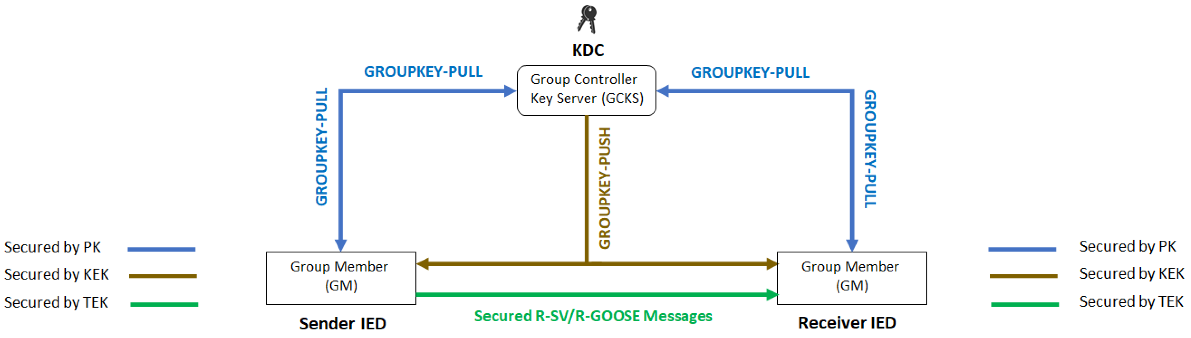
| Security Mechanisms | Phases 1 | Mutual Authentication and Authorization | GCKS authenticates GMs and registers authenticated GMs to a specific group. | PK | |
| Phase 2 | Periodic Security Policies and Keys Update | GROUPKEY-PULL | GMs request and acquire security policy and key materials from GCKS. | PK, KEK, TEK | |
| GROUPKEY-PUSH | GCKS distributes updates of security policy and key materials to authorized GMs. | KEK, TEK | |||
| P2M Architecture | Tunnel Technology | Scalability | Implementation Complexity | Public WAN Communication | Security |
|---|---|---|---|---|---|
| GRE | Point-to-Point tunnel | No | Low | Yes | IPsec |
| DMVPN | Point-to-Multipoint tunnel | Yes | High | Yes | IPsec, NHRP authentication |
| GETVPN | Tunnel-less | Yes | High | No | GDOI, IPsec with Address Preservation |
| Communication | Architecture | Configuration | Statistical Analysis Results | Communication-Based Protection | |||||
|---|---|---|---|---|---|---|---|---|---|
| Logic Selectivity (100 ms) | LOM (300 ms) | ||||||||
| 1st Centile (ms) | Mean Delay (ms) | 99th Centile (ms) | Packet Loss (%) | Total Number Messages | Communication Reliability (%) | Communication Reliability (%) | |||
| 4G | GRE | R_GOOSE_over_GRE_over_IP | 23.2 | 66.3 | 155.5 | 0.000 | 28,746 | 88.0 | 100.0 |
| Signed_R_GOOSE_over_GRE_over_IP | 23.6 | 71.6 | 149.8 | 0.000 | 27,440 | 81.7 | 100.0 | ||
| R_GOOSE_over_GRE_over_IPsec | 23.5 | 70.7 | 156.6 | 0.000 | 28,996 | 82.5 | 100.0 | ||
| Signed_R_GOOSE_over_GRE_over_IPsec | 24.1 | 73.5 | 152.2 | 0.000 | 29,411 | 80.0 | 100.0 | ||
| DMVPN | R_GOOSE_over_mGRE_over_IP | 21.0 | 72.4 | 166.9 | 0.000 | 28,605 | 77.2 | 100.0 | |
| Signed_R_GOOSE_over_mGRE_over_IP | 22.0 | 80.7 | 164.5 | 0.000 | 28,928 | 70.8 | 100.0 | ||
| R_GOOSE_over_mGRE_over_IPsec | 24.7 | 86.8 | 172.9 | 0.000 | 28,890 | 64.3 | 100.0 | ||
| Signed_R_GOOSE_over_mGRE_over_IPsec | 24.1 | 83.2 | 185.7 | 0.000 | 28,495 | 68.0 | 100.0 | ||
| 5G | GRE | R_GOOSE_over_GRE_over_IP | 14.5 | 162.3 | 340.2 | 0.000 | 27,466 | 33.2 | 89.7 |
| Signed_R_GOOSE_over_GRE_over_IP | 14.6 | 161.7 | 340.1 | 0.003 | 28,974 | 33.5 | 89.8 | ||
| R_GOOSE_over_GRE_over_IPsec | 15.3 | 126.1 | 332.6 | 0.000 | 27,667 | 52.9 | 93.6 | ||
| Signed_R_GOOSE_over_GRE_over_IPsec | 15.1 | 162.6 | 335.6 | 0.037 | 27,074 | 32.9 | 89.6 | ||
| DMVPN | R_GOOSE_over_mGRE_over_IP | 14.8 | 160.6 | 337.0 | 0.007 | 28,835 | 34.3 | 89.6 | |
| Signed_R_GOOSE_over_mGRE_over_IP | 14.9 | 157.8 | 336.3 | 0.000 | 28,779 | 35.5 | 90.2 | ||
| R_GOOSE_over_mGRE_over_IPsec | 23.3 | 164.5 | 344.0 | 0.000 | 28,671 | 33.4 | 88.3 | ||
| Signed_R_GOOSE_over_mGRE_over_IPsec | 23.3 | 166.7 | 345.3 | 0.000 | 28,664 | 32.7 | 87.7 | ||
| Architecture | Configuration | Security Mechanisms | Security Approach | Security Level | ||
|---|---|---|---|---|---|---|
| Confidentiality | Integrity | Availability | ||||
| GRE | R-GOOSE over GRE over IP | - | - | - | Insecure | NONE |
| Signed R-GOOSE over GRE over IP | - | Message Authentication by HMAC | - | End-to-End | LOW | |
| R-GOOSE over GRE over IPsec | IP Encryption by ESP | IP Authentication by ESP | - | Point-to-Point | MEDIUM | |
| Signed R-GOOSE over GRE over IPsec | IP Encryption by ESP | Message Authentication by HMAC, IP Authentication by ESP | - | Defense-in-Depth | HIGH | |
| DMVPN | R-GOOSE over mGRE over IP | - | - | - | Insecure | NONE |
| Signed R-GOOSE over mGRE over IP | - | Message Authentication by HMAC | - | End-to-End | LOW | |
| R-GOOSE over mGRE over IPsec | IP Encryption by ESP | IP Authentication by ESP, Device Authentication by NHRP | - | Point-to-Point | MEDIUM | |
| Signed R-GOOSE over mGRE over IPsec | IP Encryption by ESP | Message Authentication by HMAC, IP Authentication by ESP, Device Authentication by NHRP | - | Defense-in-Depth | HIGH | |
Publisher’s Note: MDPI stays neutral with regard to jurisdictional claims in published maps and institutional affiliations. |
© 2022 by the authors. Licensee MDPI, Basel, Switzerland. This article is an open access article distributed under the terms and conditions of the Creative Commons Attribution (CC BY) license (https://creativecommons.org/licenses/by/4.0/).
Share and Cite
Jafary, P.; Supponen, A.; Repo, S. Network Architecture for IEC61850-90-5 Communication: Case Study of Evaluating R-GOOSE over 5G for Communication-Based Protection. Energies 2022, 15, 3915. https://doi.org/10.3390/en15113915
Jafary P, Supponen A, Repo S. Network Architecture for IEC61850-90-5 Communication: Case Study of Evaluating R-GOOSE over 5G for Communication-Based Protection. Energies. 2022; 15(11):3915. https://doi.org/10.3390/en15113915
Chicago/Turabian StyleJafary, Peyman, Antti Supponen, and Sami Repo. 2022. "Network Architecture for IEC61850-90-5 Communication: Case Study of Evaluating R-GOOSE over 5G for Communication-Based Protection" Energies 15, no. 11: 3915. https://doi.org/10.3390/en15113915
APA StyleJafary, P., Supponen, A., & Repo, S. (2022). Network Architecture for IEC61850-90-5 Communication: Case Study of Evaluating R-GOOSE over 5G for Communication-Based Protection. Energies, 15(11), 3915. https://doi.org/10.3390/en15113915