Abstract
This paper presents the results of comparative studies on the implementation of machine learning methods in the damage intensity assessment of masonry buildings. The research was performed on existing residential buildings, subjected to negative impacts of the industrial environment induced by coal mining plants during their whole technical life cycle. The research was justified on the grounds of safety of use, as well as potential energy losses and CO2 emissions generated by the inefficient management of building materials resources resulting from poor planning of retrofitting. In this field, the research is in line with the global trends of large-scale retrofitting of existing buildings in European countries due to their thermal insulation parameters and seismic hazard. By combining this with the effects of material degradation throughout the technical lifecycle of buildings, the proposed methods allow for a more efficient approach to maintaining quality management of large groups of buildings, which is part of the sustainable development framework. Due to the multidimensionality of the undertaken problem and the necessity of mathematical representation of uncertainty, it was decided to implement a machine learning approach. The effectiveness of the following methods was analysed: probabilistic neural network, support vector machine, naive Bayes classification and Bayesian belief networks. The complexity of individual methods dictated the order of the adopted research horizon. Within such a research plan, both model parameters were learned, and model structure was extracted from the data, which was applied only to the approach based on Bayesian networks. The results of the conducted analyses were verified by assuming classification accuracy measures. Thus, a method was extracted that allows for the best realisation of the set research objective, which was to create a classification system to assess the intensity of damage to masonry buildings. The paper also presents in detail the characteristics of the described buildings, which were used as input variables, and assesses the effectiveness of the obtained results in terms of utilisation in practice.
1. Introduction
Damage to buildings is generally considered according to two criteria: safety and serviceability. They constitute the basis for the design and are verified during the technical life cycle of the building’s structures. However, currently, along with the development of the idea of energy-saving construction and the reduction of CO2 emissions in the atmosphere, the scope of requirements for building structures has been extended to include energy demand and durability requirements. The above aspects are included in the idea of sustainable development in construction [1,2]. Currently, the result of such activities is the ongoing transformation of the previously applicable safety and serviceability criteria, including socio-economic and environmental aspects [3]. Therefore, in the analysis of the damage process, the number of necessary factors to consider also increases. Some are also characterised by a large degree of uncertainty, which is most often described in probabilistic notation [4]. This, in turn, enforces the use of complex tools, such as multiple-criteria decision-making (MCDM) systems in the design process [5,6].
When considering the failure phenomenon from the point of view of structural mechanics, this process is initiated when the permissible threshold of the potential elastic deformation energy stored in a given structural element is exceeded [7,8]. It is the main criterion in the design of building structures and determines the maintenance of safety and acceptable levels of serviceability [9]. In turn, looking through the prism of the current requirements in the field of energy characteristics of buildings, damage often contributes to the development of leaks and moisture on the wall surfaces. They affect the deterioration of the thermal insulation properties of building partitions (walls and roofs) and generate increased demand for thermal energy needed to dry moisture and heat rooms. In this context, damage manifests itself more as being detrimental to serviceability, including the energy characteristics of buildings. Therefore, the correct prediction of the intensity of damage, especially in the case of existing building structures, may turn out to be crucial in terms of effectively preventing the loss of thermal properties, especially in the case of energy-efficient construction [10] or passive [11].
In the described case of a large group of masonry buildings located in a mining area, we deal with both threats, i.e., safety hazards and deterioration of performance characteristics affecting serviceability [12]. This is because these buildings are subjected to temporary or long-term impacts from the ground throughout their technical life cycle. Transient impacts include mining tremors, which result from a disturbance in the equilibrium of the rock mass, which leads to the release of a large amount of stored potential energy. This effect manifests itself at the surface in the form of ground vibrations and constitutes a kinematic loading for buildings located on the affected area [13]. In turn, the long-term impact results from the influence of large-scale subsidence as a direct result of underground mining exploitation or indirectly related hydrogeological disturbances [14].
Both of these effects constitute an additional load on the structure of building objects and often cause an increase in the stress of their load-bearing elements, which results in the phenomenon of damage.
Considering that the coal mining industry still operating in some countries is a pillar of the energy sector, it can be assumed that this method of obtaining energy, in addition to environmental pollution, also generates negative effects in the form of damage, which should be considered in terms of safety, socio-economic problems and environmental.
The last issue, which is not without significance for the global trend of reducing energy expenditure and releasing CO2 into the atmosphere, is the production of building materials [15,16]. Unfortunately, ineffective predictions of the range and intensity of damage at the stage of determining the extent of retrofit or repair work required, especially in existing buildings, contribute to the waste of building materials already at the stage of their production [17]. Given the large number of buildings at risk of damage, the overestimation is so large that they can cause a significant loss of irreversible energy and contribute to a further increase in CO2 emissions (Figure 1).
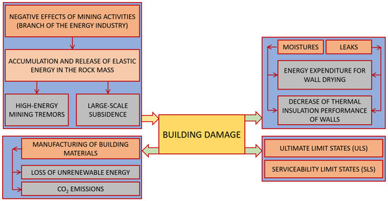
Figure 1.
Distribution of data for the variable relating to the year of construction of buildings.
When assessing the damage in individual masonry buildings, numerical methods, such as FEM [18,19], DEM [20,21] or FDEM [22,23] can be used. Unfortunately, when the damage risk assessment of a large number of buildings is required, the numerical computational approach becomes ineffective. What is more, the attempt to model such a large set of structures is almost impossible from a practical point of view.
Therefore, advanced statistical methods dedicated to analysing large datasets are applicable in such cases. This group includes methods from the field of artificial intelligence (AI), in particular, machine learning (ML). Data for such studies are acquired in situ and contain all the necessary information to map the process of damage in building structures.
A similar strategy is also very often adopted to assess the risk of buildings in seismic areas [24] or areas subject to the risk of floods [25], tsunamis [26] or tornadoes [27].
This paper presents the results of analyses carried out on a wide group of buildings subjected to the influence of the industrial environment of mines. Regarding the assessment of this phenomenon, the problem addressed in this paper shows several analogies to the impact of an exceptional natural environment on buildings.
2. Characteristics of the Mining Impact on Building Structures in the Context of Damage Occurrence
Synthetically, this chapter presents fundamental information on the negative consequences of mining impacts on building structures, particularly on the risk of damage resulting from such influences.
The implementation of the assumed research goals required collecting data on the impacts of the mining industrial environment. During the passage of underground mining exploitation, deformation occurs on the ground surface. In order to relate terrain deformation with the problem of surface development risk, detailed measurements of horizontal and vertical displacements were made. These measures are inclinations (T), curvatures (K) and horizontal deformations (ε) of terrain. As a result of geodetic measurements [28] or on the basis of model studies, it is possible to determine the values of the above-mentioned parameters.
Figure 2 is presented and interpreted schematically as the process of creating a mining basin.
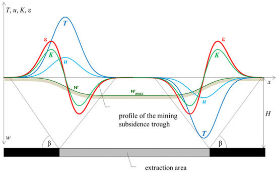
Figure 2.
Distribution of surface deformation indicators over the extraction area: (ε) horizontal ground strain; (u) vertical displacement; (T) slope; (K) ground curvature; (H) depth of cover; (β) the angle of impact [29].
The behaviour of the building in any position on the basin is shown in Figure 3. As a result of soil deformation, the building moves from its initial 1–2–3–4 position to the 1′–2′–3′–4′ position. In this process, when treating the object as a solid block, there is a vertical lowering (wb) and a horizontal shift (ub) of the building S’s geometric centre, and the building’s rotation, determined by its deflection Tb. Additional settlement of Δsb may also occur, resulting from the horizontal loosening of the soil and causing the building to assume the position of 1′′–2′′–3′′–4′′ [24] finally.
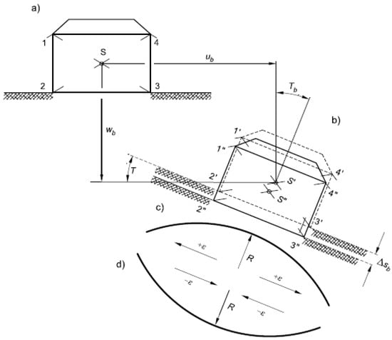
Figure 3.
Diagram of the building in any position on the basin: (a) starting position; (b) position after displacement; (c) convex basin rim; (d) concave basin rim [30]. Reproduced with permission from [30]; published by Wydawnictwo ITB, 2021.
In this position, two situations can be distinguished: the convex or concave rim of the mining basin.
Figure 4 shows the schematic damages in buildings located on the convex and concave edges of the mining basin. Examples of real mining damages will be shown in Section 4.
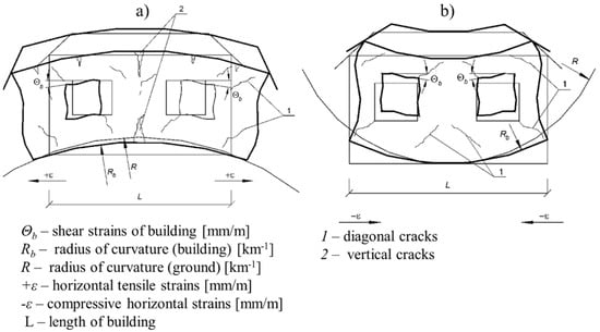
Figure 4.
Diagram of damages in buildings located on a: (a) convex edge of the mining basin; (b) concave edge of the mining basin [30]. Reproduced with permission from [30]; published by Wydawnictwo ITB, 2021.
From 2011 to 2017, the analysed residential buildings were subject to the influence of coal mining exploitation. Table 1 presents the characteristic parameters of the conducted mining operation.

Table 1.
Characteristic parameters of mining operations in the analysed area.
Building a database appropriate for the analysis requires collecting information on mining influences in the locations of individual buildings. For this purpose, information on the forecasted values of horizontal soil deformation (ε-cf. Figure 2) was collected. The values of the mining influences result from mining forecasts regularly verified and approved by the results obtained on the geodesic measuring lines run along streets and at scattered points located on buildings. Figure 5 presents the quantity of buildings affected by the influence of horizontal ground deformations, with an accuracy of 0.5 mm/m. By using the influence of horizontal deformations, the resulting categories of the mining area were determined [30].
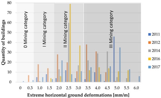
Figure 5.
Occurrence of horizontal ground deformations [mm/m] at the location of analysed buildings from 2011 to 2017.
Due to the scattered and irregular values of horizontal deformations, it was decided to use the mining terrain category as a parameter defining the impact of mining operations on buildings.
3. Technical Specification of the Investigated Buildings
For basic analysis, a qualified group of 207 buildings was examined. During the field research, information about the buildings was collected and placed in a database.
Traditional multi-family residential buildings were erected in the period from the end of the 19th century to the 1940s. They were built in a compact, semi-compact development and as free-standing, fully or partially with a basement. The buildings were erected as two, three or four storeys.
Foundations are usually made of stone or brick. The walls in the basement storey level are made of stone or brick, while the walls of the upper storeys are usually brick. The basement ceilings are mostly ceramic on steel beams, less often in the form of vaults. Occasionally, the occurrence of a concrete floor on steel beams was observed. In the levels of the above-ground storeys, wooden ceilings, section ceilings in staircases and, occasionally, concrete ceilings on steel beams were made. The vast majority of door and window lintels are brick, with an arched or flat shape. The structure of stairs in the area of staircases is usually made of wood or steel, and less often, concrete.
Most of the analysed buildings were secured against the impact of mining exploitation during their use. Such reinforcement consisted of the buildings’ total or partial anchoring with steel bars in the ceiling levels.
Single-family buildings are low-rise buildings with a height of up to two above-ground storeys. In traditional brick technology, these buildings were erected until 2017, usually as free-standing or semi-compact buildings.
The construction of single-family houses is more varied and results from the construction period. Older buildings were built on stone and/or brick foundations, and newer ones on reinforced concrete foundations. Basement walls were made of stone or brick and later made of concrete blocks. The walls on the ground are made of brick or aerated concrete blocks, or ceramic blocks. Above the basement of older buildings, ceramic on steel beams, concrete on steel beams, or reinforced concrete were usually made. On the upper floors of the buildings, there is wooden, concrete on a steel beam, rib-and-slab concrete, or reinforced concrete ceilings. The ceilings of newer buildings are made of reinforced concrete or rib-and-slab concrete. Window and door lintels are mostly made from bricks, arched or flat in shape, and in some places, on steel flat bars or made from reinforced concrete in new buildings.
The mining protection of most of the older single-family houses was carried out in the phase of their use by applying an anchorage at the level of the ceilings. It is also possible to highlight some buildings, for which a perimeter reinforced concrete band was made at the level of the foundations. Newer structures were made with protection for the III or IV categories of the mining area with additionally reinforced concrete benches and ties, rib-and-slab concrete or concrete ceilings and ceilings with peripheral reinforced concrete rings.
Field research conducted for the 207 buildings concerned the designation of:
- Geometry: length, width, number of overground storeys, building area, volume, length of the building sequence, dilation method, the shape of the building, basement, variable level of foundation, variable building height;
- Construction as: foundation type, the material of basement wall, the material of the walls higher than the basement, mining influence securities, the ceiling above the basement, the ceiling above higher floors, lintels, additional data about anchoring;
- Other technical data: year of construction, repair factor, technical condition (natural wear), category of deformation resistance.
Below, in a graphical form in Figure 6, Figure 7, Figure 8, Figure 9, Figure 10, Figure 11, Figure 12, Figure 13, Figure 14, Figure 15, Figure 16, Figure 17 and Figure 18, examples of distributions of the collected data are presented in the form of histograms (Figure 6, Figure 7, Figure 8, Figure 9, Figure 10 and Figure 11) and bar graphs (Figure 12, Figure 13, Figure 14, Figure 15, Figure 16, Figure 17 and Figure 18).
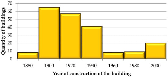
Figure 6.
Distribution of data for the variable relating to the year of construction of buildings.
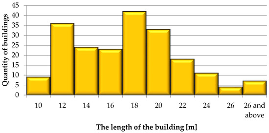
Figure 7.
Distribution of data for the variable relating to the length of the buildings [m].
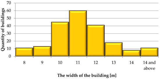
Figure 8.
Distribution of data for the variable relating to the width of the buildings [m].
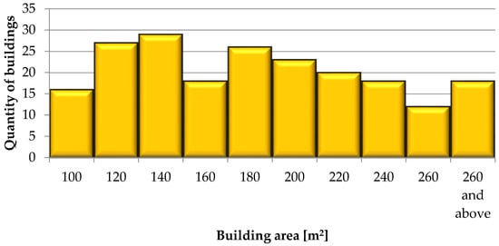
Figure 9.
Distribution of data for the variable relating to the building area [m2].
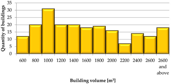
Figure 10.
Distribution of data for the variable relating to the building volume [m3].
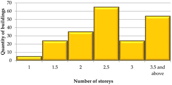
Figure 11.
Distribution of data for the variable relating to the number of storeys.
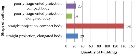
Figure 12.
Distribution of data for the variable relating to the shape of a building.

Figure 13.
Distribution of data for the variable relating to the basement of a building.

Figure 14.
Distribution of data for the variable relating to the type of foundation.

Figure 15.
Distribution of data for the variable relating to the basement’s wall materials.
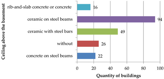
Figure 16.
Distribution of data for the variable relating to the ceiling above the basement.
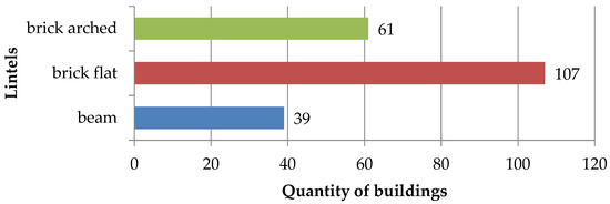
Figure 17.
Distribution of data for the variable relating to door and window lintels.
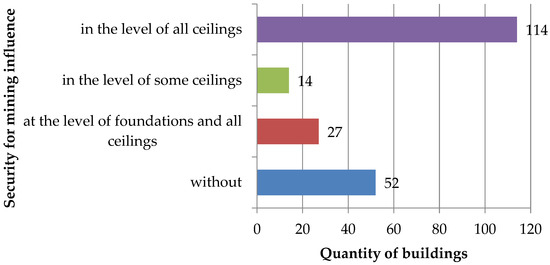
Figure 18.
Distribution of data for the variable relating to security for mining influences.
4. Damage Morphology in the Analysed Group of Buildings
Each building is classified into one of the four damage categories. These categories take into account the extent and intensity of damage and threats to the safety of the facility and its users [31].
The adopted building damage categories are described below:
- Possible damage in the form of slight scratches on the plaster of ceilings and walls, no structural damage.
- More intense damage to finishing and non-structural elements, i.e., scratching façade and internal wall plaster, trimming ceiling and wall plaster, scratching or local separation of soffits.
- Damages to structural elements; in the event of further deformation that can influence the extent, intensity and location of damages that may lead to the local loss of stability of structural elements or loss of bearing capacity.
- Damage that currently threatens the local bearing capacity of its elements; buildings with tremendous natural wear of structural elements.
Examples of damages for individual categories are presented in Figure 19.
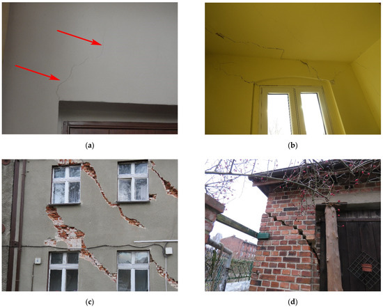
Figure 19.
Examples of damages in a building classified as: (a) damage category 1; (b) damage category 2; (c) damage category 3; (d) damage category 4.
Figure 20 shows the distribution of buildings damage categories from 2011 to 2017.
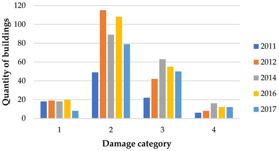
Figure 20.
Distribution of data for the variable relating to building damage categories in different years.
Finally, taking into account multiple damage checks for the selected 207 buildings, research material was collected containing 594 cases.
5. Characteristics of the Implemented Machine Learning Methods
Further activities were commenced with the database containing data on the area’s development (Section 3) and the impact of the industrial environment as mining operations (Section 2).
Bearing in mind the implementation of the assumed objectives of the study, further research focused on the classification methods because they allow obtaining prediction results in accordance with the adopted criterion of the intensity of damage to buildings described in Section 4.
An important advantage of the methods selected and described below is the possibility of adopting probabilistic notation at the stage of inference of a given system, as well as presenting the results of calculations in probabilistic notation, which can be interpreted as the risk of a given event.
By using the above information, a review of various machine learning methods was carried out, of which four were selected that can be used in the construction of the damage risk assessment model, and the methodology of which is presented below.
5.1. Probabilistic Neural Network
Neural networks are made up of individual computing units (neurons) that are connected in parallel. They are characterised by the presence of multiple inputs and one output. Neural networks can be used for both regression and classification tasks.
PNN is a specific network that learns to estimate the probability density function distributed over many so-called nuclei whose centres are represented by the data presented at the input [32].
Estimating the probability density functions (PDF) is based on the nuclear approximation [33,34]. Each of the analysed cases (observations) is located at a certain point in the input space, and a cluster of cases close to each other indicates an area of high probability density. On the other hand, regions distant from known cases are characterised by a probability density that goes down to zero. In nuclear estimation, simple functions (“kernel”) are located where each available case occurs, and then they are added together to obtain an estimate of the total probability density function. The parameter determining the shape of the probability density function is the smoothing parameter σ.
There are four layers in the PNN: input, pattern, summation and output [32]. The pattern layer consists of radial neurons that have parameters copied directly from the training data, and each corresponds to one case. Each of the radial neurons is modelled by a Gaussian function centred over the area bounded by the values of the variables of a specific training pattern. In the case of classification of each class in the summation layer, one neuron corresponds. Each of the summation neurons has connections from those radial neurons that have been positioned over the pattern centres of the training dataset belonging to that class. There are no connections between sum neurons and other classes of radial neurons. The output neuron sums the values appearing at the outputs of the sum neurons belonging to each class. Therefore, the output neuron value is proportional to the estimators of the nuclear probability density functions for different classes and may be an estimate of the probability of belonging to particular classes.
5.2. Support Vector Machine
The support vector machine was developed by Vapnik and has been in development since the 1970s [35,36]. It is a specific type of neural network that uses various activation functions and implements a learning method based on quadratic programming. SVM networks are used for both classification and regression tasks. Originally, this method was dedicated only to the problems of dichotomous (two-class) classification. Currently, it can also be used to obtain multiple classes when multiple classifications are carried out. The SVM method is also characterised by the fact that it can use various types of activation functions, including linear, polynomial, radial or sigmoidal functions [37].
According to the SVM method, the classification task is to find the optimal hyperplane that generates the widest margin of separation between patterns belonging to different classes [38]. Support vectors are very important; they are points in the data space that are the most difficult to classify and define the location of the separation hyperplane [39]. The obtained results are strongly influenced by the regularisation parameter C and the width of the functions of the γ nuclei. The higher the regularisation parameter C value, the narrower the margin of separation and the number of supporting vectors is reduced [40,41]. The γ parameter refers to the width of the assumed nucleus functions, and with its low values, the “range of influence” of the learning cases is greater [42].
The results obtained from using the SVM allow for the classification of new cases into one of the classes but do not provide information about the probability of this event. However, a method allows the transformation of a fixed lattice to probabilistic notation [43,44,45], in which the distance from the separation margins determines the probability values.
5.3. Naive Bayes Classification
In the naive Bayesian classifier, the algorithm assesses the probability of the occurrence of particular classes for the given input variables. The result is the prediction of the class that has the highest probability of occurrence of all classes.
NBC uses the Bayesian theorem concerning the conditional probability distribution. Using it requires much computational effort related to considering many conditional probabilities, which can be simplified by assuming that the input variables are independent of each other. Such an assumption of independence is often very optimistic and allows for a clear simplification of the calculations.
On the basis of the training dataset, two procedures are used to build the NBC classifier model:
- Maximum likelihood estimation (MLE), which maximises the conditional probability, is understood here as a verifiable thesis about the occurrence of individual classes for the training data;
- Maximum a posteriori estimation (MAP) maximises a posteriori probability of the occurrence of individual classes for the training set.
5.4. Bayesian Belief Network
The Bayesian belief network can be interpreted as an acyclic directed acyclic graph (DAG), which consists of nodes (variables) and the edges connecting them [46,47,48].
The graph structure encodes information about the interdependencies between the individual variables X = {X1, …, XN}. In terms of meaning, BBN represents the joint probability distribution over the set of random variables X [49].
For discrete variables, the model parameters are represented in the form of a multi-monomial conditional probability table (CPT). The total distribution is subject to decomposition on the basis of conditional local distributions . They are described above for each random variable Xi in relation to the corresponding set of conditioning variables (parents) . This formulation is possible thanks to Pearl [50,51] and his concept of conditional independence. Such activities enable a noticeable reduction in the number of relationships that do not show cause-effect relationships. It also makes it easier for the user to interpret the network’s structure.
The BBN learning procedure consists of two stages: structure learning and parameter learning [47,49,52].
There are three different approaches to learning BBN network structure from data: score-based structure learning, constraint-based structure learning, and hybrid algorithms [49,53,54]. The risk of damage to buildings can be determined using a number of variables with a seemingly small contribution. It has been found in the course of many studies described, among others [55,56,57]. Taking this into account and the characteristics of all described methods of learning BBN from data, it was decided to use the score-based approach in the further part of the research.
The second stage of creating a Bayesian network is learning the parameters, which result from the network shape determined at the structure learning stage. Generally, for a fixed network structure, the determination of θ results from the probability of the output variable occurring for the given input variables. This can be interpreted as counting the number of records for different conditions of the state combination of the parameterised vertex and its predecessors. These parameters are usually determined on the basis of the expectation maximisation algorithm (EM), which consists of determining the locally optimal estimator of the highest likelihood of parameters [58].
A very important additional advantage of the BBN method is the possibility of inferring in two directions and thus using the Bayesian network for diagnosis or prediction.
6. Results of Conducted Analyses
This chapter describes the methodology for creating the individual classifiers and presents a traditional way to determine the learning sets of the input data.
The measures used to evaluate the classification accuracy are presented and interpreted, which provided the foundation for the final comparison and selection of the most effective method.
In order to carry out the planned research, the database for analysis was first prepared. The next step was to build different models using four selected machine learning methods: PNN, SVM, NBC, BBN. From among the created models, on the basis of original criteria, the optimal model of damage risk assessment was selected.
The individual ML models were built in the R development environment [59]. The following packages were used to build the appropriate models: yap [60], e1071 [61], bnlearn [62], naivebayes [63], bnclassify [64], gRain [65,66] and caret [67].
6.1. Preparation of Analysis Data
In the process of analysing data preparation, all variables were discretised in terms of their further use in the learning process [68]. The categories of numerical variables were selected so that the number of cases in each category was not lower than 5% of the size of the entire set. Such a selection of categories influenced the preservation of the homogeneity of the database in terms of teaching individual models.
The dataset has been divided into training and test sets. The division was proposed in the proportion of 80:20. The stratified sampling approach was applied [69] to maintain the completeness of the patterns for the entire model building process. This allows for the retention of complete information, both for the learning process and for the later testing stage.
By keeping the above-mentioned procedures, the sets were separated, the number of which was, respectively, 478 cases in the training set and 116 cases in the test set. The proposed division was analogous to all the methods used in the research.
In accordance with the requirements for each method covered by the study, a training set was used only for learning, and a test set was used to evaluate the created models.
6.2. Applied Measures for Assessing the Classification Accuracy
The error matrix was used as a commonly used measure of classification correctness assessment to compare ML methods results. Table 2 shows an example of a confusion matrix.

Table 2.
Confusion matrix for a binary classification.
Overall accuracy is the essential comparative parameter [70] (1).
Additional parameters in the assessment were:
- Precision [70] (2):
- Recall [70] (3):
A very important feature in building models based on ML methods is the generalisation of knowledge obtained during learning. The relative difference in classification accuracy was calculated for the training set and test set (ΔACC), allowing for a reasonable comparison of the generalising abilities of individual models.
The obtained results and detailed descriptions are included in Section 6.3, Section 6.4, Section 6.5, Section 6.6 and Section 6.7. The division of data into training and test sets has been preserved. These matrices indicate the results concerning the classification accuracy and the average precision and recall, according to (1)–(3).
6.3. The Results for the PNN Method
For the construction of the PNN classifier, the yap package [60] in R was used, taking into account the standardisation of the variables. Standardisation of variables is the operation on their values, as a result of which the variable obtains the mean expected value of zero and the standard deviation equal to one.
It is very important for this method to determine the optimal width of the Gaussian functions of the nuclei, characterised by the parameter σ [32]. The optimal selection of this parameter was made by performing 4-fold cross-validation [71], and the optimisation method was the golden ratio method.
The obtained σ parameter value was 1.47. Optimising the value of this parameter made it possible to obtain the highest classification accuracy for the test set.
In accordance with the parameters specified in Section 6.2, the prepared model was assessed in terms of the classification correctness of the training and testing sets and its generalisation properties. Table 3 presents the results.

Table 3.
Confusion matrix for the PNN classifier—Accuracy of classification, average precision and average recall for training and test sets.
The created PNN classifier shows a very good classification accuracy, which was 94.77% for the training set. The obtained results are satisfactory for the test set, with a classification accuracy of 78.45%. The generalisation capacity of the model is assessed as insufficient (ΔACC = 16.32%).
6.4. The Results for the SVM Method
The SVM classifier was built using the e1071 package [61] in R.
The SVM method with radial functions of the nuclei was used in the research. For the classification problem formulated in this way, the hyperparameters C and γ were determined by optimisation using the grid search method [72]. The e1071 package offers this possibility by implementing the tune.svm function [61]. The procedure of optimal selection of hyperparameters assumes 10-fold cross-validation. On the basis of the analysis performed, the optimal hyperparameters were designated with the following values: C = 10, γ = 0.1.
The SVM classifier, created for the extracted optimal values of the C and γ hyperparameters, was characterised by the number of supporting vectors equal to 390. The number of supporting vectors in relation to all patterns used during learning is therefore 81.80% of the size of the training set. This proves the high complexity of the model, which may translate into lowering its generalisation properties. Table 4 presents the results.

Table 4.
Confusion matrix for the SVM classifier—accuracy of classification, average precision and average recall for training and test sets.
The created SVM classifier shows a very good classification accuracy, which was 95.40% for the training set. The obtained results are satisfactory for the test set, with a classification accuracy of 72.41%. Based on the classification accuracy results, the generalisation capacity of the model is assessed as insufficient (ΔACC = 22.99%).
6.5. The Results for the NBC Method
The NBC classifier was made with the use of four packages in the R software [61,63,64,73]. The best classification accuracy results were obtained for the classifier built using the naivebayes package [63]. The results presented below apply to this model.
The algorithm implemented in this package detects and assigns classes to individual variables [74]. The maximum likelihood method was used to determine the parameters for the CPT.
It was also necessary to use the Laplace smoothing parameter in order to build a valid NBC classifier. For lower values of this parameter, the classification accuracy increases. Unfortunately, along with the increase in its classification accuracy, its effectiveness in unusual cases noticeably deteriorates [12]. As a result of the multiple analyses carried out, it was found that good classification accuracy was obtained for the parameter equal to the value of pL = 10, and, equally important, the appropriate generalising properties were maintained. Table 5 presents the results.

Table 5.
Confusion matrix for the NBC classifier—accuracy of classification, average precision and average recall for training and test sets.
The created NBC classifier shows a good classification accuracy, which was 83.89% for the training set. The obtained results are satisfactory for the test set, with a classification accuracy of 75.86%. The generalisation capacity of the model is assessed as satisfactory (ΔACC = 9.57%).
6.6. The Results for the BBN Method
In order to carry out the analyses in accordance with the BBN’s methodology, possible interactions of individual variables with each other were assumed.
The selected method of teaching classifiers has a significant impact on the network structure obtained with the use of BBN. Eight different methods of learning the network structure were selected, and their results were analysed. Accordingly, these methods are described in the bnclassify [64] and bnlearn [62] packages.
From among the analysed learning methods, Chow-Liu’s Tree Augmented Naive Bayes (TAN-CL) allowed us to obtain the best results. The selected method of training is the result of combining two simpler methods: the Tree Augmented Naive Bayes method (TAN) [75] with the Chow-Liu variable link detection algorithm [76].
The driving parameter in the model construction is the model fit measure that serves as a target for score-based optimisation. The influence of selected objective functions on the obtained results was analysed: AIC, BIC and log-likelihood (loglik); and the best results were obtained using the AIC criterion. Table 6 presents the results.

Table 6.
Confusion matrix for the BBN classifier—accuracy of classification, average precision and average recall for training and test sets.
The created BBN classifier shows a good classification accuracy, which was 83.89% for the training set. The obtained results are also good for the test set, with a classification accuracy of 87.07%. The generalisation capacity of the model is assessed as very good (ΔACC = 3.79%).
6.7. Comparison of Results Obtained by Different ML Methods
In order to compare all the results obtained with the use of machine learning methods, they were summarised in Table 7. The comparative parameters are the ACC classification accuracy and the average values of PPV precision and TPR sensitivity.

Table 7.
Comparisons of classification parameters for all used ML methods.
The following conclusions were drawn from the comparison of the results:
- The highest scores for a training set were obtained for the PNN and SVM methods, but the results for the test set were not good enough;
- The results for the NBC method were very irregular and depended on the used package; the best of them was comparable with the BBN method;
- The BBN methods allow for obtaining the best results for the test set, and their results for the training set are good.
7. Conclusions
The presented research illustrates the effectiveness of selected ML methods for damage risk assessment in buildings subjected to external influences from the industrial environment generated by underground mining operations. The methods have been selected on the basis of the specifics of each method so that it is possible to assess the risk of damage in a probabilistic form. A gradation of methods was made from the least to the most complex. As a result of multiple analyses, results have been obtained, allowing us to state the effectiveness of each of the applied methods.
The best results of the research were obtained with the use of the Bayesian belief network machine learning method with the TAN-CL AIC structure learning method.
The selection of the BBN-based methodology as the most effective approach broadens the scope of applying the obtained model for practical purposes. In addition to generating responses on the level of risk of failure, it allows for the revision of the resulting cause-and-effect connections and the use of such a model in diagnostic cases, which very often occur in practice and are aimed at determining the causes of the failure state. In addition, such a system is very flexible in terms of computation because it is fed with new data and easily updates its parameters. Therefore, it makes it a potentially very effective tool for the real-time damage risk assessment and allows it to be used in a broader sense as a component of the SHM (structural health monitoring) [77] system operating in accordance with the IoT (Internet of Things) ideology [78].
In the course of further work, studies on the impact of damaged masonry walls on the building’s energy demand are taken into account. The damage categories used in the research have a different impact on the safety of building use, their energy demand and additional CO2 emissions, which requires their further verification.
Author Contributions
Conceptualisation, L.C., J.R. and L.S.; methodology, L.C. and J.R.; software, L.C.; validation, L.C. and J.R.; formal analysis, L.C., J.R. and L.S.; investigation, L.C. and J.R.; resources, L.C. and L.S.; data curation, L.C. and J.R.; writing—original draft preparation, L.C. and J.R.; writing—review and editing, L.C. and J.R.; visualisation, L.C. and J.R.; supervision, J.R. and L.S.; project administration, J.R.; funding acquisition, L.S. All authors have read and agreed to the published version of the manuscript.
Funding
This research received no external funding.
Institutional Review Board Statement
Not applicable.
Informed Consent Statement
Not applicable.
Data Availability Statement
The data presented in this study are available on request from the corresponding author. The data are not publicly available because they were taken from studies carried out for private enterprises.
Conflicts of Interest
The authors declare no conflict of interest.
References
- D’Amico, B.; Myers, R.J.; Sykes, J.; Voss, E.; Cousins-Jenvey, B.; Fawcett, W.; Richardson, S.; Kermani, A.; Pomponi, F. Machine Learning for Sustainable Structures: A Call for Data. Structures 2019, 19, 1–4. [Google Scholar] [CrossRef]
- Marzouk, M.; Azab, S.; Metawie, M. BIM-based approach for optimizing life cycle costs of sustainable buildings. J. Clean. Prod. 2018, 188, 217–226. [Google Scholar] [CrossRef]
- Geiker, M.R.; Michel, A.; Stang, H.; Lepech, M.D. Limit states for sustainable reinforced concrete structures. Cem. Concr. Res. 2019, 122, 189–195. [Google Scholar] [CrossRef]
- Aghababaei, M.; Mahsuli, M. Component damage models for detailed seismic risk analysis using structural reliability methods. Struct. Saf. 2019, 76, 108–122. [Google Scholar] [CrossRef]
- Zavadskas, E.K.; Antucheviciene, J.; Vilutiene, T.; Adeli, H. Sustainable Decision-Making in Civil Engineering, Construction and Building Technology. Sustainability 2018, 10, 14. [Google Scholar] [CrossRef]
- Siksnelyte, I.; Zavadskas, E.K.; Streimikiene, D.; Sharma, D. An Overview of Multi-Criteria Decision-Making Methods in Dealing with Sustainable Energy Development Issues. Energies 2018, 11, 2754. [Google Scholar] [CrossRef]
- Sousamli, M.; Messali, F.; Rots, J.G. A total-strain based orthotropic continuum model for the cyclic nonlinear behavior of unreinforced brick masonry structures. Int. J. Numer. Methods Eng. 2022, 128, 1813–1840. [Google Scholar] [CrossRef]
- Drougkas, A.; Sarhosis, V.; D’Alessandro, A.; Ubertini, F. Homogenisation of masonry structures subjected to seismic loads through matrix/inclusion micromechanics. Structures 2022, 38, 375–384. [Google Scholar] [CrossRef]
- Eurocode, C.E.N.; European Committee for Standardization. Design of Structures for Earthquake Resistance; European Committee for Standardization: Brussels, Belgium, 1990. [Google Scholar]
- Mohanta, A.; Das, S.; Mohanty, R.N. Building envelope trade-off method integrated with BIM-based framework for energy-efficient building envelope. Archit. Eng. Des. Manag. 2021, 17, 516–536. [Google Scholar] [CrossRef]
- Tian, Z.; Zhang, X.; Jin, X.; Zhou, X.; Si, B.; Shi, X. Towards adoption of building energy simulation and optimization for passive building design: A survey and a review. Energy Build. 2018, 158, 1306–1316. [Google Scholar] [CrossRef]
- Rusek, J. The point nuisance method as a decision-support system based on Bayesian inference approach. Arch. Min. Sci. 2020, 65, 117–127. [Google Scholar] [CrossRef]
- Norén-Cosgriff, K.M.; Ramstad, N.; Neby, A.; Madshus, C. Building damage due to vibration from rock blasting. Soil Dyn. Earthq. Eng. 2020, 138, 106331. [Google Scholar] [CrossRef]
- Guzy, A.; Witkowski, W.T. Land subsidence estimation for aquifer drainage induced by underground mining. Energies 2021, 14, 4658. [Google Scholar] [CrossRef]
- He, Z.; Zhu, X.; Wang, J.; Mu, M.; Wang, Y. Comparison of CO2 emissions from OPC and recycled cement production. Constr. Build. Mater. 2019, 211, 965–973. [Google Scholar] [CrossRef]
- Huang, L.; Krigsvoll, G.; Johansen, F.; Liu, Y.; Zhang, X. Carbon emission of global construction sector. Renew. Sustain. Energy Rev. 2018, 81, 1906–1916. [Google Scholar] [CrossRef]
- Purchase, C.K.; Al Zulayq, D.K.M.; O’brien, B.T.; Kowalewski, M.J.; Berenjian, A.; Tarighaleslami, A.H.; Seifan, M.; O’brien, B.T.; Kowalewski, M.J.; Berenjian, A.; et al. Circular economy of construction and demolition waste: A literature review on lessons, challenges, and benefits. Materials 2022, 15, 76. [Google Scholar] [CrossRef]
- Giardina, G.; van de Graaf, A.V.; Hendriks, M.A.N.; Rots, J.G.; Marini, A. Numerical analysis of a masonry façade subject to tunnelling-induced settlements. Eng. Struct. 2013, 54, 234–247. [Google Scholar] [CrossRef]
- Giardina, G.; Hendriks, M.A.N.; Rots, J.G. Sensitivity study on tunnelling induced damage to a masonry façade. Eng. Struct. 2015, 89, 111–129. [Google Scholar] [CrossRef]
- Dimitri, R.; Tornabene, F. A parametric investigation of the seismic capacity for masonry arches and portals of different shapes. Eng. Fail. Anal. 2015, 52, 1–34. [Google Scholar] [CrossRef]
- Dimitri, R.; De Lorenzis, L.; Zavarise, G. Numerical study on the dynamic behavior of masonry columns and arches on buttresses with the discrete element method. Eng. Struct. 2011, 33, 3172–3188. [Google Scholar] [CrossRef]
- Chen, X.; Wang, H.; Chan, A.H.; Agrawal, A.K.; Cheng, Y. Collapse simulation of masonry arches induced by spreading supports with the combined finite-discrete element method. Comput. Part. Mech. 2021, 8, 721–735. [Google Scholar] [CrossRef]
- Chen, X.; Wang, X.; Wang, H.; Agrawal, A.K.; Chan, A.H.C.; Cheng, Y. Simulating the failure of masonry walls subjected to support settlement with the combined finite-discrete element method. J. Build. Eng. 2021, 43, 102558. [Google Scholar] [CrossRef]
- Mangalathu, S.; Sun, H.; Nweke, C.C.; Yi, Z.; Burton, H.V. Classifying earthquake damage to buildings using machine learning. Earthq. Spectra 2020, 36, 183–208. [Google Scholar] [CrossRef]
- Arabameri, A.; Saha, S.; Mukherjee, K.; Blaschke, T.; Chen, W.; Ngo, P.T.T.; Band, S.S. Modeling spatial flood using novel ensemble artificial intelligence approaches in northern Iran. Remote Sens. 2020, 12, 3423. [Google Scholar] [CrossRef]
- Sublime, J. The 2011 tohoku tsunami from the sky: A review on the evolution of artificial intelligence methods for damage assessment. Geosciences 2021, 11, 133. [Google Scholar] [CrossRef]
- Adrianto, I.; Trafalis, T.B.; Lakshmanan, V. Support vector machines for spatiotemporal tornado prediction. Int. J. Gen. Syst. 2009, 38, 759–776. [Google Scholar] [CrossRef]
- Tajduś, K. Analysis of horizontal displacement distribution caused by single advancing longwall panel excavation. J. Rock Mech. Geotech. Eng. 2015, 7, 395–403. [Google Scholar] [CrossRef]
- Zięba, M.; Kalisz, P. Impact of horizontal soil strain on flexible manhole riser deflection based on laboratory test results. Eng. Struct. 2020, 208, 109921. [Google Scholar] [CrossRef]
- Kawulok, M. Diagnozowanie Budynków Zlokalizowanych na Terenach Górniczych; Instytut Techniki Budowlanej: Warsaw, Poland, 2021. [Google Scholar]
- Kawulok, M. Osąd eksperta w ochronie istniejących obiektów budowlanych na terenach górniczych. Przegląd Górniczy 2015, 71, 38–43. [Google Scholar]
- Specht, D. Probabilistic Neural Networks. Neural Netw. 1990, 3, 109–118. [Google Scholar] [CrossRef]
- Bishop, C. Neural Networks for Pattern Recognition; Oxford University Press: Oxford, UK, 1995. [Google Scholar]
- Parzen, E. On Estimation of a Probability Density Function and Mode. Ann. Math. Stat. 1962, 33, 1065–1076. [Google Scholar] [CrossRef]
- Vapnik, V.N. The Nature of Statistical Learning Theory; Springer: New York, NY, USA, 2000; ISBN 978-1-4419-3160-3. [Google Scholar]
- Burges, C. A Tutorial on Support Vector Machines for Pattern Recognition. Data Min. Knowl. Discov. 1998, 2, 121–167. [Google Scholar] [CrossRef]
- Hsu, C.-W.; Chang, C.-C.; Lin, C.-J. A Practical Guide to Support Vector Classification. 2003. Available online: https://www.csie.ntu.edu.tw/~cjlin/papers/guide/guide.pdf (accessed on 31 March 2022).
- Schölkopf, B.; Smola, A. Support Vector Machines and Kernel Algorithms. In The Handbook of Brain Theory and Neural Networks; The MIT Press: Cambridge, MA, USA, 2002; pp. 1119–1125. [Google Scholar]
- Haykin, S. Neural Networks and Learning Machines, 3rd ed.; Pearson Education: Upper Saddle River, NJ, USA, 2009; Volume 127, ISBN 0750302259. [Google Scholar]
- Mrówczyńska, M. Klasyfikatory neuronowe typu SVM w zastosowaniu do klasyfikacji przemieszczeń pionowych na obszarze LGOM. Zesz. Nauk. Pol. Akad. Nauk IGSMiE 2014, 86, 69–82. [Google Scholar]
- Hastie, T.; Tibshirani, R.; Friedman, J. The Elements of Statistical Learning; Springer Series in Statistics; Springer: New York, NY, USA, 2009; ISBN 978-0-387-84857-0. [Google Scholar]
- Vert, J.; Tsuda, K.; Schölkopf, B. A Primer on Kernel Methods. In Kernel Methods in Computational Biology; MIT Press: Cambridge, MA, USA, 2004; pp. 35–70. [Google Scholar]
- Murphy, K. Machine Learning A Probabilistic Perspective; Massachusetts Institute of Technology: Cambridge, MA, USA, 2012. [Google Scholar]
- Platt, J. Probabilistic Outputs for Support Vector Machines and Comparisons to Regularized Likelihood Methods. Adv. Large Margin Classif. 2000, 10, 61–74. [Google Scholar]
- Wu, T.F.; Lin, C.-J.; Weng, R.C. Probability estimates for multi-class classification by pairwise coupling. J. Mach. Learn. Res. 2004, 5, 975–1005. [Google Scholar]
- Cichosz, P. Systemy Uczące Się; Wydawnictwo Naukowo-Techniczne: Warszawa, Poland, 2000; ISBN 83-204-2544-1. [Google Scholar]
- Scutari, M. Dirichlet Bayesian network scores and the maximum relative entropy principle. Behaviormetrika 2018, 45, 337–362. [Google Scholar] [CrossRef]
- Chomacki, L.; Rusek, J.; Słowik, L. Selected artificial intelligence methods in the risk analysis of damage to masonry buildings subject to long-term underground mining exploitation. Minerals 2021, 11, 958. [Google Scholar] [CrossRef]
- Scutari, M.; Graafland, C.E.; Gutiérrez, J.M. Who learns better Bayesian network structures: Accuracy and speed of structure learning algorithms. Int. J. Approx. Reason. 2019, 115, 235–253. [Google Scholar] [CrossRef]
- Pearl, J. Probabilistic Reasoning in Intelligent Systems: Networks of Plausible Inference; Elsevier: Amsterdam, The Netherlands, 2014. [Google Scholar]
- Pearl, J. Probabilistic Reasoning in Intelligent Systems; Elsevier: Amsterdam, The Netherlands, 1988; Volume 8, ISBN 9780080514895. [Google Scholar]
- Kratzer, G.; Furrer, R. Information-Theoretic Scoring Rules to Learn Additive Bayesian Network Applied to Epidemiology. arXiv 2018, arXiv:1808.01126. [Google Scholar]
- Nagarajan, R.; Scutari, M.; Lèbre, S. Bayesian Networks in R; Springer: Berlin/Heidelberg, Germany, 2013; ISBN 9781461464457. [Google Scholar]
- Koski, T.; Noble, J. A review of Bayesian networks and structure learning. Math. Appl. 2012, 40, 51–103. [Google Scholar] [CrossRef]
- Firek, K.; Rusek, J. Partial Least Squares Method in the Analysis of the Intensity of Damage in Prefabricated Large-Block Building Structures. Arch. Min. Sci. 2017, 62, 269–277. [Google Scholar] [CrossRef][Green Version]
- Rusek, J. Creating a model of technical wear of building in mining area, with utilization of regressive SVM approach. Arch. Min. Sci. 2009, 54, 455–466. [Google Scholar]
- Rusek, J. Application of Support Vector Machine in the analysis of the technical state of development in the LGOM mining area. Eksploat. I Niezawodn. Maint. Reliab. 2016, 19, 54–61. [Google Scholar] [CrossRef]
- Gadowska-dos Santos, D. Sieć Bayesa jako narzędzie wspomagające zarządzanie ryzykiem operacyjnym w banku. Probl. Zarz. 2017, 15, 125–144. [Google Scholar] [CrossRef]
- R Core Team. R: A Language and Environment for Statistical Computing; R Core Team: Vienna, Austria, 2019. [Google Scholar]
- Liu, W. Package ‘yap’. In Yet Another Probabilistic Neural Network. 2020. Available online: https://cran.r-project.org/web/packages/yap/yap.pdf (accessed on 31 March 2022).
- Meyer, D.; Dimitriadou, E.; Hornik, K.; Leisch, F.; Meyer, D.; Maintainer, A.; Leisch, F. The e1071 Package. 2006. Available online: https://cran.r-project.org/web/packages/e1071/e1071.pdf (accessed on 31 March 2022).
- Scutari, M.; Ness, R. Package ‘Bnlearn’. 2019. Available online: https://cran.r-project.org/web/packages/bnlearn/bnlearn.pdf (accessed on 31 March 2022).
- Majka, M. Package Naivebayes: High Performance Implementation of the Naive Bayes Algorithm in R. 2019. Available online: https://cran.r-project.org/web/packages/naivebayes/naivebayes.pdf (accessed on 31 March 2022).
- Mihaljević, B.; Bielza, C.; Larrañaga, P. bnclassify: Learning Bayesian Network Classifiers. R J. 2019, 10, 455. [Google Scholar] [CrossRef]
- Højsgaard, S. Graphical Independence Networks with the gRain Package for R. J. Stat. Softw. 2012, 46, 37–44. [Google Scholar] [CrossRef]
- Højsgaard, S. Bayesian Networks in R with the gRain Package. 2022. Available online: https://cran.r-project.org/web/packages/gRain/vignettes/grain-intro.pdf (accessed on 31 March 2022).
- Kuhn, M.; Wing, J.; Weston, S.; Williams, A.; Keefer, C.; Engelhardt, A.; Cooper, T.; Mayer, Z.; Ziem, A.; Scrucca, L.; et al. Package ‘Caret’ R topics Documented. R J. 2020, 223, 7. [Google Scholar]
- Uusitalo, L. Advantages and challenges of Bayesian networks in environmental modelling. Ecol. Modell. 2007, 203, 312–318. [Google Scholar] [CrossRef]
- Ramezan, C.A.; Warner, T.A.; Maxwell, A.E. Evaluation of sampling and cross-validation tuning strategies for regional-scale machine learning classification. Remote Sens. 2019, 11, 185. [Google Scholar] [CrossRef]
- Chicco, D.; Jurman, G. The advantages of the Matthews correlation coefficient (MCC) over F1 score and accuracy in binary classification evaluation. BMC Genomics 2020, 21, e41882. [Google Scholar] [CrossRef]
- Zhong, M.; Coggeshall, D.; Ghaneie, E.; Pope, T.; Rivera, M.; Georgiopoulos, M.; Anagnostopoulos, G.; Mollaghasemi, M.; Richie, S. Gap-based estimation: Choosing the smoothing parameters for probabilistic and general regression neural networks. IEEE Int. Conf. Neural Netw. Conf. Proc. 2006, 19, 1870–1877. [Google Scholar] [CrossRef][Green Version]
- Syarif, I.; Prugel-Bennett, A.; Wills, G. SVM parameter optimization using grid search and genetic algorithm to improve classification performance. Telkomnika 2016, 14, 1502–1509. [Google Scholar] [CrossRef]
- Scutari, M. Learning Bayesian Networks with the bnlearn R Package. J. Stat. Softw. 2010, 35, 1–22. [Google Scholar] [CrossRef]
- Majka, M. Introduction to Naivebayes package Main Functions. 2020. Available online: https://cran.r-project.org/web/packages/naivebayes/vignettes/intro_naivebayes.pdf (accessed on 31 March 2022).
- Long, Y.; Wang, L.; Sun, M. Structure extension of tree-augmented naive bayes. Entropy 2019, 21, 721. [Google Scholar] [CrossRef] [PubMed]
- Russell, S.; Norvig, P. Artificial Intelligence: A Modern Approach; Prentice Hall: Hoboken, NJ, USA, 2020; ISBN 0131038052. [Google Scholar]
- Song, G.; Wang, C.; Wang, B. Structural Health Monitoring (SHM) of Civil Structures. Appl. Sci. 2017, 7, 789. [Google Scholar] [CrossRef]
- Scuro, C.; Sciammarella, P.F.; Lamonaca, F.; Olivito, R.S.; Carni, D.L. IoT for structural health monitoring. IEEE Instrum. Meas. Mag. 2018, 21, 4–14. [Google Scholar] [CrossRef]
Publisher’s Note: MDPI stays neutral with regard to jurisdictional claims in published maps and institutional affiliations. |
© 2022 by the authors. Licensee MDPI, Basel, Switzerland. This article is an open access article distributed under the terms and conditions of the Creative Commons Attribution (CC BY) license (https://creativecommons.org/licenses/by/4.0/).