Abstract
A heat pump is an energy-effective technique to provide heating for buildings using available heat sources from the environment. Solar irradiation and ambient air are the most accessible heat sources among different heat sources; however, they are unstable for a day or several days. A large volume of the heat storage tank is usually required to provide a stable heating supply. As the most commonly used media for heat storage, water has a limitation on the heat storage temperature, i.e., above 0 °C, limiting its density of energy storage. This paper presents an experiment that evaluated the performance of a developed ice source heat pump used for assisting a solar heating system. The ice source heat pump can extract both sensible heat and the latent heat of water freezing, which doubles the density of energy storage and increase the heating output by 50%. The experiment results showed that the solar heating system tested could supply hot water at the highest temperature of 60 °C (with intense sun irradiation) and the lowest temperature of 40 °C (without sun irradiation). The min COP of the ice source heat pump was three, measured when the heat pump extracted heat from the ice water. This technology could be used for domestic heating with 50% reduced heat storage volume.
1. Introduction
Solar irradiance is a clean and renewable energy source. Solar heating technology has been well developed and widely used; however, solar collectors are only productive during the day when domestic heating demand is at its lowest, and in the evening, once demand increases, the heat is no longer available [1]. In Denmark, solar heating encountered even more problems in winter due to the frequent and prolonged cloudy sky that blocks most of the direct normal irradiance (DNI), resulting in the temperature of the heat collected being too low (e.g., lower than 10 °C) to be used for space heating. One solution is using a heat pump to raise the temperature for space heating [2,3]; however, the freezing point of water is a limitation for a heat pump to extract heat when water is used as the medium of heat storage. Yang et al. 2021 [4] reviewed the solar-assisted air source heat pumps approach for domestic heating. The review results showed that more research is still required to improve the performance of such a combined system and reduce initial cost compared with existing heating systems based on hydrocarbon combustion.
In whatever designs of a solar heating system, heat storage is required to maintain heat supply when solar irradiation is unavailable. Krockenberger et al., 2014 [5] presented a small heat pump-assisted solar thermal system designed for the climate in Indianapolis and Atlanta, where a 300 L heat storage tank was used for heat storage. In the Danish winter climate, a 300 L water tank is far from enough for heat storage, especially when there is no DNI during the day. To collect enough heat, a giant water tank is required to store sufficient heat, especially the low-temperature heat, to be pumped into the heating space. For a single-family house in Denmark, the volume of a heat storage water tank was estimated to be at least 1 m3 or bigger, which is not suitable to be installed in a house. Even if adding an anti-freezing agent can decrease the freezing point of water, it will also reduce the COP of the heat pump when operating at a lower evaporating temperature and results in higher power consumption of heat pumps.
As a matter of fact, there is a large amount of energy that can be extracted from water when it freezes into ice (i.e., 334 kJ/kg, equivalent to 80 °C of temperature change of the same amount of water), and the temperature during this heat extraction process remains constant at 0 °C without decreasing the COP of the heat pump. If the latent heat of water freezing can be used as the heat source of a heat pump, the volume of heat storage in a solar heating system can be reduced by about 50%. So far, a solar heating system using such technology has not been reported.
This paper presents a new technique—an ice source heat pump (ISHP)—that breaks the barrier of water freezing when a heat pump extracts heat from the water and utilizes the latent heat of water when freezing into ice as the heat source of a heat pump.
2. Materials and Methods
A prototype solar heating system with ISHP was developed for a laboratory test. The test was conducted using an actual solar panel for collecting solar heat during a Danish winter climate from January to April 2020.
2.1. Ice Source Heat Pump (ISHP)
The concept of the ice source heat pump is created based on an invention of newly developed ice diffusion interrupting technology [6] that can prevent the diffusion of ice formed on the surface of a water pipe with super-cooled water flow. The ice diffusion interrupter installed at the outlet of a plate heat exchanger can effectively prevent ice from forming on the surface of a pipe and diffusing back into the heat exchanger, blocking the heat exchanger; therefore, an ordinary plate heat exchanger can be modified to generate super-cooled water at −2 to −3 °C without freezing (no anti-freezing agent is required). When the super-cooled water leaves the heat exchanger, it enters a specially designed ice crystal promoter [7,8], where the super-cooled water freezes in the form of ice slurry. In this process, the frozen water releases its phase change heat of 335 kJ/kg and warms up the super-cooled water to 0 °C. The ice slurry can be transported through a pipe without the risk of further freezing.
Combining this technology with a heat pump, the heat pump’s evaporator can produce super-cooled water that will then freeze to ice slurry in a controlled manner. The ice slurry flows into a heat storage tank and keeps the temperature in the tank at 0 °C. The heat pump continuously sucks the 0 °C water from the tank and pumps the heat released from the phase change of ice formation until all water in the tank freezes into ice. In such a process, the heat source of the heat pump is the phase change energy of water when freezing into ice and, therefore, the name of the ice source heat pump (ISHP) was given to the technology [9,10].
2.2. Design of the Solar Heating System with ISHP
The ISHP has been developed with capacities from several hundred watts to several hundred kilowatts levels. The ISHP designed for this study had a heating capacity of 4.6 kW when extracting heat from the cold water of 0 °C to produce hot water of 40 °C. The design of the ISHP at this capacity was merely selected based on the heating/cooling capacity of the lab for conducting the test. The test solar heating system with ISHP was designed as shown in Figure 1. It consists of a heat collecting system including a solar panel to collect solar heat irradiation and fan coil 1 to collect heat from ambient air, a heat storage water tank, an ISHP, and a hot water buffer tank with fan coil 2 to simulate the heating load.
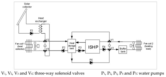
Figure 1.
Schematic diagram of the solar heating system with ISHP.
A vacuum tube solar panel was used to collect the heat of solar irradiation. To avoid freezing inside the solar panel and in the connecting water pipe, the anti-freeing agent was added to the water; however, the water inside the heat storage tank should not contain an anti-freeing agent; therefore, a plate heat exchanger was installed between the solar panel and the heat storage tank to transfer heat without mass exchange between the two water circulations. The heat from ambient air was collected by fan coil 1 during the night if the air temperature was higher than 3 °C and when ice was formed inside the heat storage tank. It was an auxiliary heat source that could be used to melt the ice. This low-temperature air heat source is often available in the Danish climate during the night when no solar irradiation is available.
The heat storage tank was designed with three water circuits. It collected heat from the heat collecting system and provided heat directly for space heating when the water temperature was higher than 40 °C or provided heat to the heat pump when the water temperature was lower than 35 °C. Figure 2 shows the design of the heat storage tank.
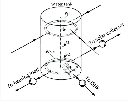
Figure 2.
Design of the heat storage tank (Win: water inlet, Wout: water outlet, WF: water filter, IS: ice slurry inlet, S1 and S2: ice level sensors).
The heat storage tank was made of double-lays stainless steel (1.5 mm inside and 0.5 mm outside) with 50 mm 45 kg/m3 polyurethane foam thermal insulation in between. The max heat transfer between the ice water in the tank and the ambient air in the lab was calculated as less than 8.5 W, which was negligible compared to the heating output of the ISHP. The temperature of water in the tank was measured on top and at the bottom of the water tank. The difference in temperatures measured on top and at the bottom of the water tank was very little when ice was formed on top (i.e., less than 0.2 °C when the system reached a steady state). Since the water outlets were at the bottom of the tank, the water temperature measured at the bottom was used for controlling the system and shown in the results of this paper representing the temperature of water in the heat storage tank.
The ISHP was designed based on the requirement of space heating using radiant heating systems. The hot water supply of the heat pump was designed at 40 °C, which is suitable for the radiant low-temperature heat system that is the most popular domestic heating system used in Denmark and will also be used in the future. Using R134a as the refrigerant, the COP of this ISHP was above 3 when providing hot water of 40 °C at the heat source temperature of 0 °C.
Fan coil 2 was used to simulate heating load, and the buffer tank was used to mimic the thermal lag of a building. Since the ISHP operated in on/off control mode, the thermal lag was required to avoid too rapid on and off the compressor in the heat pump.
The whole system was controlled by a computer with the following algorithm. When the water temperature in the heat storage tank is above 40 °C (40 °C is sufficient for most radiant heating systems), the hot water is used directly for space heating without starting the heat pump. When the water temperature in the tank goes below 35 °C, the heat pump will start to provide space heating. The heat pump will first run in a normal operation mode to pump heat from the heat storage tank to the heating space. The water temperature in the tank will decrease with the heat pump’s operation. When the water temperature in the tank drops to 0 °C, the ice source heat pump mode will be initiated automatically to generate ice slurry to the heat storage tank. In the ice source heat pump operation mode, ISHP pumps the latent heat released from the ice formation to the heating space. The COP of the heat pump will first decrease with the decreasing of water temperature in the heat storage tank before the ice slurry is generated. When the ice slurry is pumped into the heat storage tank, the temperature in the tank remains constant at 0 °C, and the COP of the heat pump will also remain constant without further decrease.
Temperatures in the system were measured by Pt100 temperature sensors using Agilent 34972A data logger with a resolution of 0.01 °C. The accuracy of the whole temperature logger (including sensors and the datalogger) was calibrated with an accuracy better than ±0.2 °C. The power consumption of the heat pump was measured by the Chauvin Arnoux F27 power meter with an accuracy of ±2%. The water flow rate was measured by Grundfos MFS multi-flow sensors with an accuracy of ±1% FS.
2.3. Experimental Setup
The developed solar heating system with ISHP was installed in a lab for testing solar heating devices. A vacuum tube solar heat collecting panel was installed on the roof of the lab to collect solar heat. The heat generated from the ISHP was rejected by a fan coil unit to simulate the heat load of a heated space. An electric heater was used to simulate the heat collector of ambient air (fan coil 1). It supplied 1.5 °C of recirculated water during the night when water temperature from the solar collector decreased to lower than 2 °C. The whole system was controlled by a computer and automatically operated for two months during February and March of 2020, for the data collection. Figure 3 shows the ISHP and the solar collector installed in the solar lab and ice slurry in the heat storage tank.
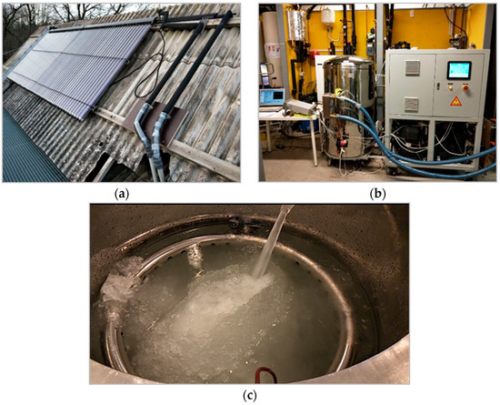
Figure 3.
(a) Vacuum solar collector used in the experiment; (b) the ISHP installed in the solar lab; (c) the ice slurry in the heat storage tank.
3. Results
Before testing the complete ISHP solar heating system, the COP of the ISHP was tested at various hot water output temperatures when it operated in the ice mode, i.e., the temperature of the heat source was kept constant at 0 °C. The results of the COP test are shown in Table 1. The ice packing factor was between 45–55%.

Table 1.
Performance of the ISHP tested in the lab.
The results of the solar heating experiment from March 2 to March 11 in 2020 are shown in Figure 4. The figure shows the water temperatures in the bottom of the heat storage tank and the heating supply temperature collected for ten consecutive days.
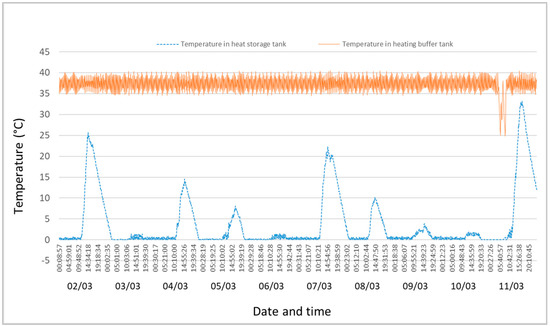
Figure 4.
Water temperature in the heat storage tank and the heating buffer tank between March 2 and 11, 2020.
Figure 4 shows the data collected in early March when the weather was relatively cold. The outdoor air temperature and solar irradiation measured in the same location during the same period are shown in Figure 5. Comparing Figure 4 and Figure 5, it can be observed that the water temperature in the heat storage tank mainly followed the strength of solar irradiation during the day. At night when no solar irradiation was available, the water temperature in the heat storage tank decreased to 0 °C, and the heat pump extracted latent heat of the water for space heating and produced ice. During this period, the water temperature in the heat storage tank was maintained constantly at 0 °C until the following day, when sun irradiation was available again. After absorbing solar heat and the heat from ambient air, all ice was melted, and the water temperature increased during the daytime. It can be observed that the temperature in the heat storage tank decreased to 0 °C every day during the night, which means that the ISHP had to extract latent heat of the ice formation for heating. Each morning, a time delay on the temperature profile of the heat storage tank could be observed after the solar irradiation started. The delay was the time required to melt all the ice inside the tank by the solar irradiation.

Figure 5.
Ambient air temperature and solar irradiation in the location of the experiment between March 2 and 11, 2020.
In early March, the solar irradiation was not strong enough to heat the water in the heat storage tank to 40 °C; therefore, heating was supplied by the heat pump. The solar heat and the low-temperature heat from ambient air were stored in the heat storage tank in the form of both sensible and latent heat to be used by the ISHP.
In Figure 4, it can be observed that the heating supply temperature output from the ISHP was maintained at 35–40 °C except for a few hours on the morning of March 11. During this period, the ISHP stopped because the ice reached the inlet filter of the ISHP, which triggered the ice level sensor in the bottom of the tank and turned off the heat pump. By examining the weather data, it can be seen that it was due to three consecutive cloudy days without sufficient solar irradiation to melt the ice in the heat storage tank; however, the heating supply temperature only decreased to 25 °C, and the ISHP restarted on the morning of March 11 when the solar heat melted the ice.
The same experiment was repeated from March 28 to April 6 in 2020 when the weather was warmer with intense solar irradiation. The results are shown in Figure 6 and Figure 7. Figure 6 shows that on 7 out of the 10 days, the water temperature in the heat storage tank was heated to over 40 °C for more than 6 h by the solar irradiation during the daytime. During this period, heating was supplied directly from solar heating, and the heat pump stopped operating. On some days, the water temperature in the heat storage tank went down to 0 °C during the night, and the ISHP switched to ice mode to extract heat from the phase change of water freezing for a short time. On 3 out of the 10 days, the water temperature in the heat storage tank was lower than 40 °C due to the two consecutive days of cloudy weather on 1 and 2 April. During these three days, heating was supplied solely by the heat pump, and the heating supply temperature was still maintained at 35–40 °C.
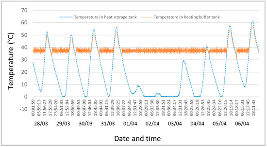
Figure 6.
Water temperature in the heat storage tank and the heating buffer tank between 28 March and 6 April 2020.
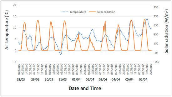
Figure 7.
Ambient air temperature and solar irradiation in the location of the experiment between 28 March and 6 April 2020.
The experiment results confirmed that the ISHP could operate smoothly and automatically switch its operation mode between the ice and normal operation mode to make full use of both sensible heat and latent heat stored in the water tank. The operation of the ISHP was very reliable.
4. Discussion
The ISHP solar heating system was developed and tested in this project. The advantages of the design are reducing the size of the water heat storage tank and utilizing a low-temperature heat source during cloudy days. These have been verified in the experiment.
The research in this experiment found that ISHP could be combined with low-temperature ambient air heat collector to utilize the heat from the low-temperature ambient air when solar irradiation was not available. This is particularly useful in Danish winter when most days are without sunshine, but the air temperature is higher than 0 °C. Since the heat storage used for the ISHP is mainly the latent heat during the phase change of water, the low-temperature heat from ambient air can be collected by melting ice whenever it is higher than 0 °C. By observing the Danish winter climate data in Figure 5 and Figure 7, it was found that most of the winter days were cloudy but warm at night, i.e., air temperatures higher than 0 °C, and many sunny days were cold at night. Due to this particular feature of the Danish winter climate, the ISHP can always collect heat from either solar irradiation or ambient air on most days in the winter season. Only in the case of several consecutive cold and cloudy days may ISHP stop operation due to lack of heat collection; however, these days are usually very few in most years (e.g., several hours in 6 days in 2020) in the Danish winter season. This makes ISHP technology particularly suitable to be used as the Danish heating technology. In the case of frigid days without sunshine, the heat storage in the tank may not be sufficient to provide continuous space heating for several days, which is a common problem of solar heating systems. In such a case, electric heating may be required. This should be on minimal days a year in Denmark.
In the ISHP solar heating system, water is used as a phase change material for heat storage. Compared to the solar-assisted heat pump heating system using PCM for heat storage, the ISHP technology has relatively lower COP since PCMs used for heat storage have high phase change temperature; however, the phase change temperatures for most of the PCMs are higher than 25 °C [11], which are not suitable to be used in the Danish winter when the solar collector could not provide heat with a temperature high than their phase-change temperatures, e.g., during the cloudy weather. Even if the solar collector could provide heat with the high temperature required for the PCMs, its collector efficiency would be much lower compared to that when the collector provides heat at close to 0 °C since the efficiency of a solar collector decreases greatly with increasing the temperature of the heat output [12]. Using water as the PCM requires the temperature of the heat to be slightly over 0 °C, which increases the solar heat collection by a large amount, and is the most important feature in guaranteeing continuous heating supply. Other advantages include the fact that water is cheaper, environmentally friendly, and stable.
The ambient air heat collector was simulated in this study by an electric heater to verify its effectiveness. A more realistic experiment using a real fan-coil air to water heat exchanger may be used to collect the heat from ambient air to demonstrate this design further. The main risk of using a fan-coil air–water heat exchanger to collect heat from ambient air could be the freezing of water inside the coil of the air heat collector. Adding an anti-freezing agent to the water of the coil and isolating the water of the coil from the water in the heat storage tank could solve the freezing problem as it was used by the solar collector; however, this will increase the usable temperature of the ambient air. A reliable air temperature control must be applied to cut off the airflow to the heat collector before the ambient air temperature goes down to 0 °C. Since the heat collector of ambient air only operates when the ambient air temperature is higher than 0 °C, there will be no ice formed outside the coil of the heat exchanger to block the air passage of the heat exchanger; therefore, no coil freeze problem for such a heat pump when it operates in air source heating mode. The operation of the heat pump should be very smooth.
An ice sensor was installed just above the filter to prevent ice block the filter at the water intake of the heat pump inside the heat storage tank. When the ice reaches the filter, the heat pump will be switched off. The experiment found that due to the irregular shape of the ice layer and very fine ice crystal in the ice slurry, when the ice sensor on top of the filter was triggered, there was still a lot of water inside the heat storage tank. The ice packing factor of the tank was about 50% that leaving 50% of the latent heat from the water not used. This very much reduced the effective volume of the tank; therefore, the design of the tank must be optimized to increase the ice packing factor. One possible solution could be to separate the ice from the water by a perforated plate installed above the filter of the water intake of the heat pump to allow water to flow down but keep the ice above it. So far, this is an important technique to be developed to apply ISHP [13].
This small test system is a pathfinder of the ISHP technique that utilizes the phase change of water freeze for heat storage and space heating. The operation of the ISHP tested was very smooth without any special requirements except for a 1 µm class water filter is needed to remove particles in the water. It works even with seawater, which makes it possible to be used as a seawater heat pump that operates at the freezing point to extract phase change heat of seawater (results of the study will be published elsewhere).
Without any technical barrier, the ISHP technology can be used directly in much larger scale applications, e.g., the cross-seasonal pit thermal energy storage (PTES) system [14,15,16,17]. The world’s largest PTES system has a 200,000 m3 water pit for solar heat storage [17], which requires a huge investment for pit construction. It is estimated from this study that using the ISHP technology can reduce the volume of the water pit by at least 30%, which will lead to considerable savings for the investment of such a heat plant.
By numerical simulation, Wang et al. [18] and Wang et al. [19] analyzed the economic performance of heating systems using ISHP in variers climate zones in China. The results showed that the payback time was from 2.3 to 5.1 years. The calculation by Wang et al. [19] also showed that the COP of the ISHP using R134a as a refrigerant was about 3.1 at the condensing temperature of 45 °C, which agreed very well with the experimental results of COP = 3.0 obtained from this study. It is worth noting that this is the lowest COP to operate the ISHP to provide hot water at 40 °C. Considering the heat pump used in this experiment was a 4.6 kW small one, the COP of a large heat pump could be much higher. For the PTES heating system, the additional cost of using the ISHP compared to the same design using a regular water source heat pump is only the cost of an ice diffusion interrupter and an ice crystal promoter. The cost of these two components is nearly negligible compared to the main cost of the whole system; therefore, both the energy and cost-effectiveness of the ISHP heating technology is attractive in practice.
5. Conclusions
- This pathfinder study proved that the ISHP is a very stable and ready-to-be-used technology that could effectively extend 50% heat storage capacity without increasing the storage volume. It also makes it possible to harvest heat at low solar irradiation with high efficiency of solar collection.
- The ice source heat pump solar heating system developed in this project was very successful. The test in real Danish winter confirmed the designed function of the operation. Combined with a radiant heating system with 40 °C of hot water supply, the minimum COP of the heat pump was 3, and the annual average COP could be much higher.
- Further studies on the application of ISHP for higher temperature heating supply, e.g., hot water supply at 60 to 80 °C, and in a much larger scale of heating supply, e.g., MW scale heat plant, are suggested.
- Economic analysis of the construction and operation of the solar-assisted ISHP space heating system should be studied further to evaluate its commercial feasibility.
- Except for the application in solar-assisted heat pump space heating systems, the ISHP has the potential to be applied in cross-seasonal energy storage for heating and cooling, seawater heat pumps, etc. More studies on these applications remain to be investigated further.
Author Contributions
Conceptualization, L.F.; methodology, L.F. and Y.W.; formal analysis, L.F. and Y.W.; investigation, L.F.; data curation, Y.W.; writing—original draft preparation, L.F.; writing—review and editing, L.F. and Y.W.; supervision, L.F. All authors have read and agreed to the published version of the manuscript.
Funding
This research was funded by the Bjarne Saxhofs foundation in Denmark and Jiangsu Overseas Visiting Scholar Program for University Prominent Young & Middle-aged Teachers and Presidents.
Institutional Review Board Statement
Not applicable.
Informed Consent Statement
Not applicable.
Data Availability Statement
Not applicable.
Acknowledgments
The authors acknowledge Guangdong KOLIN Energy Technology Co., Ltd. for offering their patented technology to develop the ice source heat pump used in this study.
Conflicts of Interest
The authors declare no conflict of interest. The funders had no role in the design of the study; in the collection, analyses, or interpretation of data; in the writing of the manuscript, or in the decision to publish the results.
References
- Mahon, H.; O’Connor, D.; Friedrich, D.; Hughes, B. A review of thermal energy storage technologies for seasonal loops. Energy 2022, 239, 122207. [Google Scholar] [CrossRef]
- Dannemand, M.; Furbo, S.; Perers, B.; Kadim, K.; Mikkelsen, S.E. Performance of a Solar Heating System with Photovoltaic Thermal Hybrid Collectors and Heat Pump. In Proceedings of the IAFOR International Conference on Sustainability, Energy & the Environment, Honolulu, HI, USA, 5–7 January 2017. [Google Scholar]
- Carbonell, D.; Haller, M.Y.; Frank, E. Potential benefit of combining heat pumps with solar thermal for heating and domestic hot water preparation. Energy Procedia 2014, 57, 2656–2665. [Google Scholar] [CrossRef][Green Version]
- Yang, L.; Xu, R.; Hua, N.; Xia, Y.; Zhou, W.; Yang, T.; Belyayev, Y.; Wang, H. Review of the advances in solar-assisted air source heat pumps for the domestic sector. Energy Convers. Manag. 2021, 247, 114710. [Google Scholar] [CrossRef]
- Krockenberger, K.G.; DeGrove, J.M.; Hutzel, W.J.; Foreman, J.C. Design of a Heat Pump Assisted Solar Thermal System. In Proceedings of the International High Performance Buildings Conference, West Lafayette, IN, USA, 14–17 July 2014. [Google Scholar]
- Xiao, R.; Qi, K.; Xie, F.; Wei, S. A Device That Prevents Diffusion of Ice Crystal in Supercooled Water Flow. Chinese Patent No. CN201720403308, 17 November 2017. [Google Scholar]
- Takaaki, I.; Xu, Z.; Akira, Y.; Yoshiyuki, K. Active control of phase change from supercooled water to ice by ultrasonic vibration 1. Control of freezing temperature. Int. J. Heat Mass Transf. 2001, 44, 4523–4531. [Google Scholar] [CrossRef]
- Zhang, X.; Inada, T.; Yabe, A.; Lu, S.; Kozawa, Y. Active control of phase change from supercooled water to ice by ultrasonic vibration 2. Generation of ice slurries and effect of bubble nuclei. Int. J. Heat Mass Transf. 2001, 44, 4533–4539. [Google Scholar] [CrossRef]
- Chen, M.; Fu, D.; Song, W.; Feng, Z. Performance of Ice Generation System Using Supercooled Water with a Directed Evaporating Method. Energies 2021, 14, 7021. [Google Scholar] [CrossRef]
- Du, Z. An Ice Rejection Type Ice Source Heat Pump. Chinese Patent No. CN201921752573, 12 June 2020. [Google Scholar]
- Kaygusuz, K. Experimental and theoretical investigation of latent heat storage for water based solar heating systems. Energy Convers. Manag. 1995, 36, 315–323. [Google Scholar] [CrossRef]
- Goswami, D.Y.; Kreith, F.; Kreider, J.F. Principles of Solar Engineering, 2nd ed.; CRC Press: Boca Raton, FL, USA, 2000; ISBN 978-156-032-714-1. [Google Scholar]
- Song, W.; Feng, Z.; Xiao, R. Progress of Ice Slurry Technology and Its Prosperity Applications. Adv. NR Energy 2019, 7, 129–141. [Google Scholar] [CrossRef]
- Abdulrahman, D.; Fabian, O.; Michele, B.J.; Wolfgang, S. Advances in seasonal thermal energy storage for solar district heating applications: A critical review on large scale hot-water tank and pit thermal energy storage systems. Appl. Energy 2019, 239, 296–315. [Google Scholar] [CrossRef]
- Tschopp, D.; Tian, Z.; Berberich, M.; Fan, J.; Perers, B.; Furbo, S. Large-scale solar thermal systems in leading countries: A review and comparative study of Denmark, China, Germany and Austria. Appl. Energy 2020, 270, 114997. [Google Scholar] [CrossRef]
- Tian, Z.; Zhang, S.; Deng, J.; Fan, J.; Huang, J.; Kong, W.; Perers, B.; Furbo, S. Large-scale solar district heating plants in Danish smart thermal grid: Developments and recent trends. Energy Convers. Manag. 2019, 189, 67–80. [Google Scholar] [CrossRef]
- Fan, J.; Huang, J.; Chatzidiakos, A.; Furbo, S. Experimental and theoretic investigations of thermal behavior of a seasonal water pit heat storage. In Proceedings of the Solar World Congress, Abu Dhabi, UAE, 29 October–2 November 2017. [Google Scholar]
- Wang, Y.; Song, W.; Chen, M. Study on Energy Efficiency and Economical Performance of Ice Source Heat Pump Based on Ice Slurry. Adv. New Renew. Energy 2021, 9, 48–54. [Google Scholar] [CrossRef]
- Wang, Y.; Fu, D.; Chen, M.; Song, W.; Feng, Z. Economy of ice source heat pump clean heating system in cold winter zone. Energy Storage Sci. Technol. 2021, 10, 1380–1387. [Google Scholar] [CrossRef]


Publisher’s Note: MDPI stays neutral with regard to jurisdictional claims in published maps and institutional affiliations. |
© 2022 by the authors. Licensee MDPI, Basel, Switzerland. This article is an open access article distributed under the terms and conditions of the Creative Commons Attribution (CC BY) license (https://creativecommons.org/licenses/by/4.0/).