Article

Advanced Distributed Cooperative Secondary Control of Islanded DC Microgrids

by
Anuoluwapo Aluko
*,
Elutunji Buraimoh
,
Oluwafemi Emmanuel Oni
and
Innocent Ewean Davidson
Department of Electrical Power Engineering, Durban University of Technology, Durban 4001, South Africa
*
Author to whom correspondence should be addressed.
Energies 2022, 15(11), 3988; https://doi.org/10.3390/en15113988
Submission received: 18 April 2022 / Revised: 18 May 2022 / Accepted: 19 May 2022 / Published: 28 May 2022
(This article belongs to the Special Issue Modern Electric Power Delivery Systems)

Abstract

:
In an islanded DC microgrid with multiple distributed generators (DGs), the droop control is employed to realize proportional current sharing among the DGs in the microgrid. The action of the droop control causes a deviation in the DC bus voltage which is exacerbated by the line impedance between the DG and the DC bus. In this paper, an advanced distributed secondary control scheme is proposed to simultaneously achieve accurate voltage regulation and cooperative current sharing in the islanded DC microgrid system. The proposed distributed secondary controller is introduced in the cyber layer of the system, and each controller shares information with neighbouring controllers via a communication network. The distributed technique maintains the reliability of the overall system if some part of the communication link fails. The proposed controller uses the type-II fuzzy logic scheme to adaptively select the secondary control parameters for an improved response of the controller. The sufficient conditions to guarantee the stability of the proposed controller are derived using the Lyapunov method. Comprehensive tests under different operating scenarios are conducted to demonstrate the robustness of the proposed control scheme.

1. Introduction

Owing to the growing environmental concerns and continuous depletion of fossil fuel reserves, the adoption of renewable energy systems (RESs) and large-scale energy storage systems (ESSs) have been on the rise. However, the integration of these sources gives rise to various operational and technical concerns such as congestion of transmission lines, unstable voltage profiles, and reduced reserves for frequency regulation [1]. To achieve a more stable control and flexible operation, the concept of a microgrid has been introduced in the last few decades. Microgrids are small-scale power grids that consist of distributed energy resources (DERs) or distributed generators (DGs), electric vehicles (EVs), and domestic and commercial loads [2]. They expedite the use of RESs and have the advantages of reduced losses and proximity to end-users. Microgrids can be operated in islanded or grid-connected modes, and they can have alternating current (AC), direct current (DC), or hybrid AC-DC bus configurations. In the past decade, the ubiquitous use of DC sources such as solar photovoltaic (PV) systems, battery energy storage systems (BESS), supercapacitor energy storage systems, fuel cells, and DC loads, DC microgrids have gained appreciable attention [3]. Compared to the traditional AC microgrids, DC microgrids do not have the problems of synchronization using the phase-locked loop (PLL), frequency control, reactive power control, harmonics, inrush currents, and power factor losses [4,5]. Therefore, studies have shown that DC microgrids have about 15% more efficiency when compared to AC microgrids [6].
In the DC microgrid system, the DGs are connected to the DC bus via a controlled DC/DC power electronic converter interface. The DC bus voltage regulation is the major control objective. When multiple DGs or ESSs are connected in parallel to a common DC bus, the droop control is used to achieve power sharing in the DGs and ESSs without communication links [7]. The droop control is implemented by adding a virtual (droop) resistance loop to the primary control loop of the DC/DC converter. The primary control loop consists of the proportional-integral (PI)-based current and voltage controllers that generate the voltage reference for the pulse width modulation (PWM) that switches the converter [8]. Despite the simple implementation of droop control, it has several limitations that inhibit its application. The most notable drawbacks are the voltage deviation and the current-sharing error caused by the propagation of the voltage deviation. Therefore, a higher level of control (secondary control) is required to solve the voltage deviation and current-sharing problems caused by the droop control method [9]. The secondary control may be centralized, decentralized, or distributed. The conventional approach is the centralized secondary in which the error measurement is fed into a central controller, usually a PI-type controller-, and the output of the controller is sent to the active DGs via communication links [10]. The voltage deviation and current-sharing error are the inputs to the central controller, and the output (adjustment signal) of the secondary controller enhances the voltage regulation, average power sharing, reliability, and power quality of the islanded DC microgrid. In [11], a coordinated centralized controller based on DC bus signaling was proposed for DC bus voltage regulation and maintaining the state-of-charge (SOC) of the ESS in the microgrid. In [12], the linear-quadratic Gaussian (LQG) and synergistic control strategies were used to design a centralized controller to stabilize a medium-voltage DC microgrid during large-signal disturbance(s). The drawbacks of the centralized secondary control are less flexibility and scalability, susceptibility to single-point failure, and less reliability. In the decentralized secondary control scheme, the sources in the microgrids are locally controlled. The local measurements are used as input signals to the controller to generate an appropriate adjustment signal. In [13], a decentralized droop-based control scheme was proposed to ensure voltage regulation, energy management, and SOC recovery in an islanded DC microgrid. In [14], a decentralized robust backstepping voltage controller was proposed for voltage regulation of a DC microgrid. In [15], a globally decentralized secondary control scheme was proposed for power sharing for DC loads. In [16], an adaptive coordination control strategy was proposed for the secondary control of a DC microgrid. The proposed decentralized control improved the life cycle of the battery ESS. While the decentralized secondary control is easy to implement, it has the limitation of deteriorating the overall performance of the DC microgrid because of the absence of global communication; however, the output of the controller may be sufficient to compensate for the required deviation caused by the droop control.
The distributed secondary control combines the advantages of centralized and decentralized secondary controls. In the distributed secondary control, each DG unit has its secondary controller and shares(receives) information such as voltage, output current, etc, with neighbouring secondary controllers of other DG units. The advantage of this approach is the ability to retain functionality if some part of the communication link fails; thus, there is a reduced risk of single-point failure [17]. In [18], a distributed nonlinear sliding mode control scheme was proposed for power balance in a DC microgrid considering variable power generation. In [19], a distributed cooperative control using consensus protocol was proposed to maintain the voltage profile of an islanded DC microgrid with hybrid ESS considering variable RES generation. In [20], one secondary controller was dedicated to voltage restoration, and other distributed secondary controllers were proposed to achieve proportional power allocation among the DGs in the DC microgrid. In [21], a consensus-based distributed secondary control scheme was proposed for voltage recovery and current sharing in a DC microgrid. In the proposed scheme, two PI controllers are employed for independent voltage recovery and current sharing, and the outputs of the controllers are sent to the local controllers as adjustment signals. In [22], the integral-type distributed secondary control scheme was proposed for voltage restoration and current sharing in an islanded DC microgrid.
In the aforementioned reports, the proposed schemes are based on conventional control schemes. Fuzzy logic systems have been identified as an alternative approach to provide a more robust solution to control problems in the emerging power grids such as DC microgrids [23]. The type-I fuzzy controllers are the most common type of fuzzy controllers that are easily designed with little knowledge of the system model, and they have been successfully applied in various power system problems [24,25]. However, the major limitation of the type-I fuzzy logic systems is that they are not robust enough to handle uncertainties that are associated with dynamic environments such as DC microgrids [26]. Thus, type-II fuzzy logic systems have been proposed as an efficient control scheme to overcome these uncertainties and external disturbances because they add an extra degree of freedom in the output that is provided by the footprint of uncertainty [27].
In this paper, an advanced distributed secondary control scheme is proposed for voltage regulation and average current sharing for an islanded DC microgrid. The proposed controller is based on the type-II fuzzy logic control; the inputs to the fuzzy system are the voltage deviation and the current-sharing error. The Lyapunov-based method is used to analyze the stability of the proposed controller. The theoretical and experimental analysis shows the robustness of the proposed secondary controller to achieve the control objective in the DC microgrid.
The remainder of this paper is organized as follows: Section 2 presents the modeling of the DC microgrid; Section 3 presents the distributed secondary control scheme; Section 4 presents the proposed type-II fuzzy-based distributed secondary control for voltage regulation and current sharing in the DC microgrid; Section 5 discusses the results of the simulation; Section 6 highlights the conclusion of the paper.

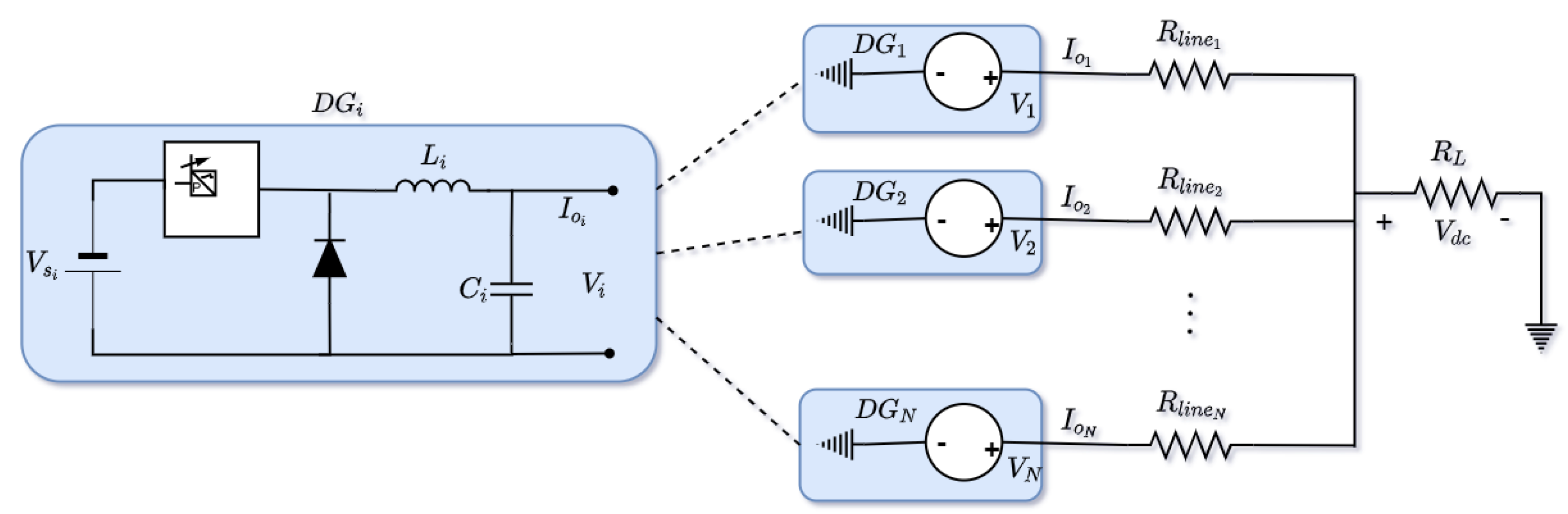
2. Basics of DC Microgrid

In this section, the preliminaries of the islanded DC microgrid is presented. The power flow and communication flow models are modeled, and the control objectives of the study system are presented.

2.1. Power Flow

The generalized physical model of an islanded DC microgrid with multiple DGs is depicted in Figure 1. Considering an islanded DC microgrid with N number of DGs connected to a common DC bus, the DGs can be represented by its Thevenin’s equivalent connected to the DC bus via the line impedance. The power flow model of the i t h DG can be mathematically expressed as
L i d I L i d t = d i · V s i V i , C i d V i d t = I L i I o i , V d c = V i R l i n e i I o i ,
where L is the filter inductance, C is the filter capacitance, d is the duty cycle of the converter, V s is the source voltage of the DG, I L is the filter inductor current, V is the output voltage of the DG, I o is the output current of the DG, R l i n e is the line impedance between the i t h DG and the DC bus, and V d c is the voltage at the DC bus. It is worth noting that the line impedance is neglected due to the presence of the LC filter that makes its effect negligible. For the DC microgrid with N DGs, the power flow equation in (1) is rewritten as
L d I L d t = d · V V , C d V d t = I L I o , V d c = V R line I o ,
where L = d i a g { L i } , C = d i a g { C i } , V s = d i a g { V s i } , R line = d i a g { R l i n e i } , V = [ V 1 , V 2 , . . . , V N ] T , I o = [ I o 1 , I o 2 , . . . , I o N ] T , I L = [ I L 1 , I L 2 , . . . , I L N ] T , and d = [ d 1 , d 2 , . . . , d N ] T .

2.2. Information Flow

In an islanded DC microgrid, the communication network ensures the timely exchange of information between the DG controllers. The flow of information is based on the topology of the communication system, usually a sparse communication network. The communication network can be mathematically represented using graph theory as
G = { V , E A } ,
where V is the set of vertices (DGs), E is the set of edges (communication link) between the DGs, and A is the adjacency matrix, A = [ a i j ] , that represents the communication weights between the DGs.

2.3. Problem Formulation and Control Objectives

In the islanded DC microgrid with more than one DG connected to a common bus, the droop control is traditionally used to achieve proportional power sharing. The droop control is embedded in the primary control loop (current and voltage PI-based controllers) of the DC/DC converter, thus acting in a decentralized way. For D G i , the voltage reference signal for current sharing based on the droop controller can be expressed as
V r e f i = V r e f R d i I o i ,
where V r e f is the reference(nominal) voltage of the DC bus, and R d is the droop resistance. Traditionally, the output voltage of the DG should track the reference voltage as
V r e f i = V r e f
By combining (2)–(5), we obtain
V d c = V r e f R l i n e i + R d i I o i
From (6), it can be inferred that the DC bus voltage, V d c , will always be unequal to the reference voltage, V r e f , because the output current, I o , will not be equal to zero. Similarly, the magnitude of the deviation is dependent on the value of the droop resistance and line impedance. Large values of the droop resistance will increase the DC bus voltage deviations, and the magnitude of the line impacts the bus voltage.
In this work, we consider the islanded DC microgrid with N DGs that should achieve average power sharing to meet the load. For a constant DC voltage, the output current-sharing ratio of D G i and D G j can be expressed as
k i I o i k j I o j = R l i n e j + R d j R l i n e i + R d i
where k i and k j are the current-sharing ratio of D G i and D G j . It is important to mention that with the current-sharing ratio, each DG may be prespecified at the design stage, usually dependent on the capacity of the DG. Considering the ESS-based DG system used in this work, the current-sharing ratio of the DGs are constant values that are prespecified. To ensure simultaneous current sharing and maintain the DC bus voltage at reference value, the control objectives of the DC microgrid are formulated as follows:
Objective 1: To achieve global voltage regulation at the DC bus, the voltage deviation must be equal to zero. This is mathematically expressed as
Δ V d c = V d c V r e f , lim t Δ V d c ( t ) = 0 .
Objective 2: To ensure average current sharing among the active DGs in the microgrid, the current-sharing error in each DG must be equal to zero. This is mathematically expressed as
Δ I o i ( t ) = k i I o i ( t ) 1 N 1 j N k j I o j ( t ) , lim t Δ I o i ( t ) = 0 .
It worth noting that Objective 1 is a global objective, i.e., one DC voltage must be maintained in the microgrid, while Objective 2 is a consensus objective, i.e., each DG must ensure Δ I o i ( t ) = Δ I o j ( t ) = = Δ I o N ( t ) . In the next section, the secondary control is proposed to meet the formulated objectives.

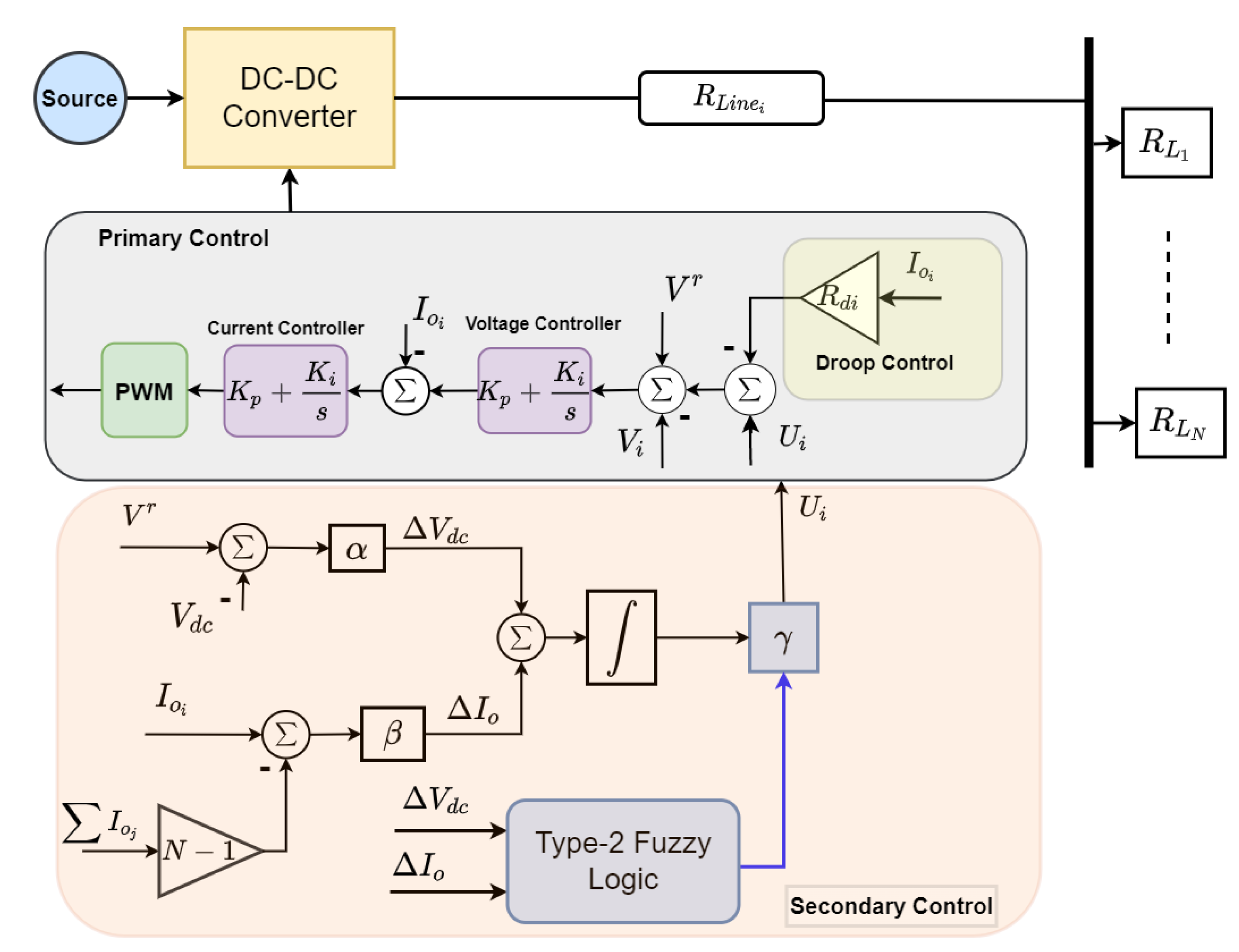
3. Distributed Secondary Control Scheme

In this section, the distributed secondary control scheme to achieve average current sharing and voltage regulation for an islanded DC microgrid is presented.

3.1. Design of Secondary Controller

In the hierarchical control scheme, the secondary controller is implemented to offset any deviation caused by the droop controller in the primary control loop. In the islanded DC microgrid, the proposed secondary control is used to generate the required voltage reference. Based on the control objectives in the previous section, the DC voltage in (6) can be regulated while ensuring average current sharing by using the secondary control, which is expressed as
V d c ( t ) = V r e f R l i n e i + R d i I o i ( t ) + U i ( t )
where U i is the adjustment signal from the proposed secondary controller that is designed as
U i ( t ) = γ i e i ( t ) d t e i ( t ) = α i Δ V d c ( t ) + β i Δ I o i ( t )
where e ( t ) is the combined current and voltage deviation; and α , β , and γ are the weights of the proposed secondary control scheme. The magnitudes of these weights affect the response of the secondary control scheme; a large value of α causes a faster convergence of Objective 1, while a large value of β leads to the faster convergence of Objective 2. To avoid the trade-off between the current-sharing and voltage regulation properties of the secondary controller, γ should be carefully designed. The design/tuning process of γ is usually complex and time-consuming due to the variability of the DC microgrid; therefore, the type-II fuzzy logic scheme is proposed for adaptive selection of γ to ensure both objectives are met simultaneously.

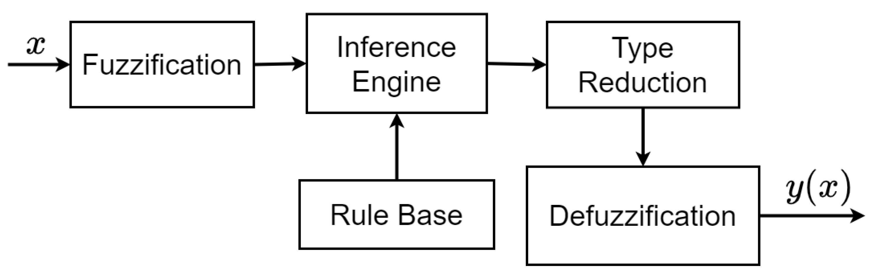
3.2. Basics of Type-II Fuzzy Logic System

The structure of the type-II fuzzy logic system is shown in Figure 2. It has three basic stages: fuzzification—conversion of the crisp input to fuzzy input; inference engine—uses the rule base to determine the fuzzy output; type reduction/defuzzification—reduces and converts the fuzzy output into crisp output [28].
The type-II fuzzy set (FS) which is connoted by F s ˜ can be expressed as
F s ˜ = ( a , b ) , μ F s ˜ ( a , b ) | a A , b J a [ 0 , 1 ] ,
where μ F s ˜ ( a , b ) is a type-II membership function (MF), a, and m are the primary and secondary variables, respectively, in which 0 μ F s ˜ ( a , b ) 1 , and J a is the primary membership of a. When all μ F s ˜ ( a , b ) = 1 , F s ˜ is an interval type-II FS. Due to the uncertainty present in the interval type-II FS, the bounds of uncertainty are defined as the footprint of uncertainty (FOU). The exterior ( μ ¯ ) of the FOU is the upper membership function (UMF), and the interior ( μ ̲ ) is the lower membership function (LMF) so that
FOU ( F s ˜ ) = a A J a ,
μ ¯ F s ˜ ( a ) FOU ¯ ( F s ˜ ) , μ ̲ F s ˜ ( a ) FOU ̲ ( F s ˜ ) a A .
The rule construction for the type-II fuzzy logic is similar to the type-1 fuzzy logic scheme. For a fuzzy system with a K rule, the jth rule can be expressed in the form:
R j : If a 1 is F s ˜ 1 , n j and a i is F s ˜ i , j and a I is F s ˜ I , j ; Then y is Y ˜ j ,
where j = (1, 2,…, K). The type reduction block maps the type-II FS into a type-1 FS by calculating the centroid of the type-II FS associated with each fired rule using
Y F s ˜ = 1 / y l , , y m ,
where y l and y m are given as
y l = i = 1 M y i μ ¯ F s ˜ y i + i = L + 1 N y i μ ̲ F s ˜ y i i = 1 L μ ¯ F s ˜ y i + i = L + 1 N μ ̲ F s ˜ y i , y m = i = 1 L y i μ ̲ F s ¯ y i + i = M + 1 N y i μ ¯ F s ˜ y i i = 1 M μ ̲ F s ¯ y i + i = M + 1 N μ ¯ F s ¯ y i .
The switching points L and M in (17) are calculated using the Karnik–Mendel (KM) algorithm [29]. The crisp output y of the type-II is computed through defuzzification using
y ( x ) = 1 2 y l + y m

4. Proposed Type-II Fuzzy-Based Distributed Secondary Control Scheme

In this section, the application of the type-II fuzzy logic scheme to achieve the control objectives of current sharing and voltage regulation is presented.

4.1. Proposed Fuzzy-Based Distributed Secondary Controller

The control framework of the proposed distributed type-II fuzzy secondary control scheme for an islanded DC microgrid is depicted in Figure 3. By convention, the primary control uses the droop method to achieve current sharing for power allocation between multiple DGs in the microgrid. The action of the droop controller leads to a deviation in the DC bus voltage of the microgrid. Thus, it is difficult to simultaneously ensure current sharing and voltage regulation using the primary controller. The secondary controller is employed to solve the limitation of the droop controller. The type-II fuzzy logic scheme is used in the proposed distributed secondary scheme. Each DG has its secondary controller and communicates with other secondary controllers of the other DGs to achieve the distributed property. The inputs to the type-II fuzzy system of D G i are the voltage deviation ( Δ V d c ) and the current-sharing error ( Δ I o i ). The output of the fuzzy-based secondary controller is the adjustment signal U i to correct the deviation caused by the primary controller. The mathematical expression of the proposed distributed type-II secondary controller is given as
U i = γ e i ( t ) d t e i ( t ) = α Δ V i + β Δ I o i γ = Ω Δ V d c , Δ I o i
where Ω ( · ) is the proposed type-II fuzzy logic scheme. The membership functions (MFs) of the fuzzy logic system are used for the nonlinear representation of the input–output characteristics of the fuzzy system. Five MFs—positive Large (PL), positive small (NS), an zero (Z), negative small (PS), and negative large (NL)—are selected for the input variables, and three MFs—large (L), medium (M), and small (S)—are selected for the output variable as shown in Figure 4. Using the fuzzy rules provided in Table 1, the If–then rules are designed in the inference engine of the fuzzy system. The output of the type-II fuzzy logic control is multiplied by the integral of the combined error to generate the adjustment signal that meets the control objectives.

4.2. Stability Analysis of Proposed Controller

Here, we provide the sufficient condition that guarantees the stable operation of the proposed distributed controller. From (2) and (10)
I ˙ o i ( t ) = 1 R l i n e , i ( V ˙ i ( t ) V ˙ d c ( t ) ) = 1 R l i n e , i U ˙ i ( t ) ( R L i n e i + R d i ) · I ˙ o i ( t ) V ˙ d c ( t ) = 1 R i U ˙ i ( t ) V ˙ d c ( t )
where R i = 2 R L i n e i + R d i . Similarly, from (3), i I s I ˙ o i = V ˙ d c j I L 1 / R l o a d j , the current and voltage derivatives of D G i with respect to the distributed secondary control input derived from (20) is given by
I ˙ o i ( t ) = 1 R i I N × 1 i I s 1 / R i D U ˙ i ( t )
V ˙ d c ( t ) = i I s 1 / R i D U ˙ i ( t )
where D = i I s 1 R i + i I L 1 / R L i . Denoting I = [ I o 1 , . . . , I N ] T , C = d i a g ( c 1 , . . . , c N ) , U = [ U 1 , . . . , U N ] T , V = [ V 1 , . . . , V N ] T , and G = d i a g ( 1 / R 1 , . . . , 1 / R N ) , we can represent (8) and (9) as
Δ V ˙ ( t ) = V ˙ d c ( t ) = 1 1 × N G D U ˙ ( t )
Δ I ˙ o ( t ) = L C 1 G Υ U ˙ ( t )
where Φ = I N × N 1 1 × N 1 N × 1 G .
Lemma 1.
Assuming a symmetric matrix Z with the property
λ m i n I Z λ m a x I
where I is an identity matrix of appropriate dimension, and λ m i n and λ m a x are minimum and maximum eigenvalues of Z . The matrix Z that satisfies the Lyapunov equation
ζ T Z + Z ζ = Q
where Q is a positive definite matrix, and ζ = α D 1 1 × N 1 N × 1 G + β L Φ .
Lemma 2.
Assuming an undirected graph L ( G ) whose objective is to achieve average current sharing given that Δ I o = L I , where I = 1 N × 1 is the solution to Δ I o = 0 .
Theorem 1.
The proposed distributed secondary controller in (19) achieves current-sharing and voltage restoration objectives given in (8) and (9), i.e., the combined deviation η ( t ) asymptotically tends to zero if the following condition is met: 1 γ λ m i n ( P ) < 0 , where λ m i n is the minimum eigenvalue of P .
Proof of Stability.
Defining a Lyapunov function
V ( t ) = e T ( t ) Z e ( t )
Taking the first derivative of (26)
V ˙ ( t ) = e ˙ T ( t ) Z e ( t ) + e T ( t ) Z e ˙ ( t )
From (19) and (23)–(25), we can derive
e ˙ ( t ) = α D 1 1 × N 1 N × 1 G U ˙ ( t ) + β L Φ U ˙ ( t )
Therefore,
V ˙ ( t ) = α D 1 1 × N 1 N × 1 G U ˙ ( t ) + β L Φ U ˙ ( t ) T Z η ( t ) + e T ( t ) Z α D 1 1 × N 1 N × 1 G U ˙ ( t ) + β L Φ U ˙ ( t )
which can be simplified as
V ˙ ( t ) = ζ T U ˙ ( t ) T Z e ( t ) + e T ( t ) Z ζ U ˙ ( t ) = ζ T U ˙ ( t ) T Z U ˙ ( t ) + U ˙ T ( t ) Z Ψ U ˙ ( t ) = U ˙ ( t ) T ( ζ T Z + Z ζ ) U ˙ ( t )
V ˙ ( t ) = 1 γ U ˙ ( t ) T Q U ˙ ( t ) V ˙ ( t ) 1 γ λ m i n ( Z ) | | U ( t ) | | 2
If λ m i n > 0 , then V ˙ ( t ) < 0 . Therefore, from Lemma 1, the sufficient condition for the distributed secondary controller to be asymptotically stable requires that the coefficient γ of the proposed distributed secondary controller is designed to be positive. □

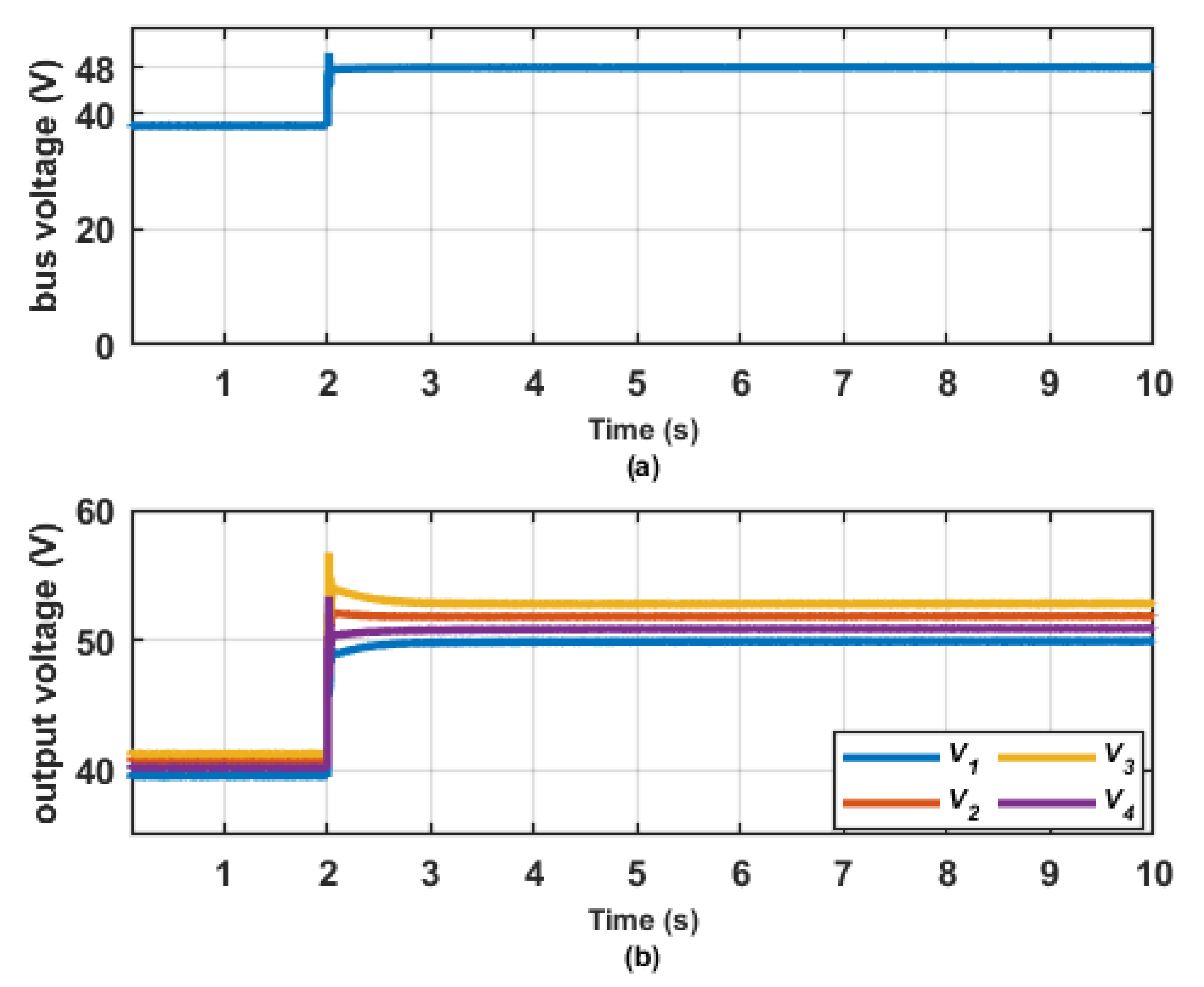
5. Simulation and Discussion

In this section, the performance of the proposed type-II fuzzy-based secondary control scheme for the islanded DC microgrid is investigated. The DC microgrid has four DGs (N = 4), each with its primary and secondary controls. The primary control operates using the decentralized feature, while the proposed secondary control adopts the distributed feature using a communication network. The DC microgrid is developed in MATLAB/Simulink and experimentally validated in real-time using the OPAL-RT simulator. The parameters of the microgrid are given in Table 2 [30].

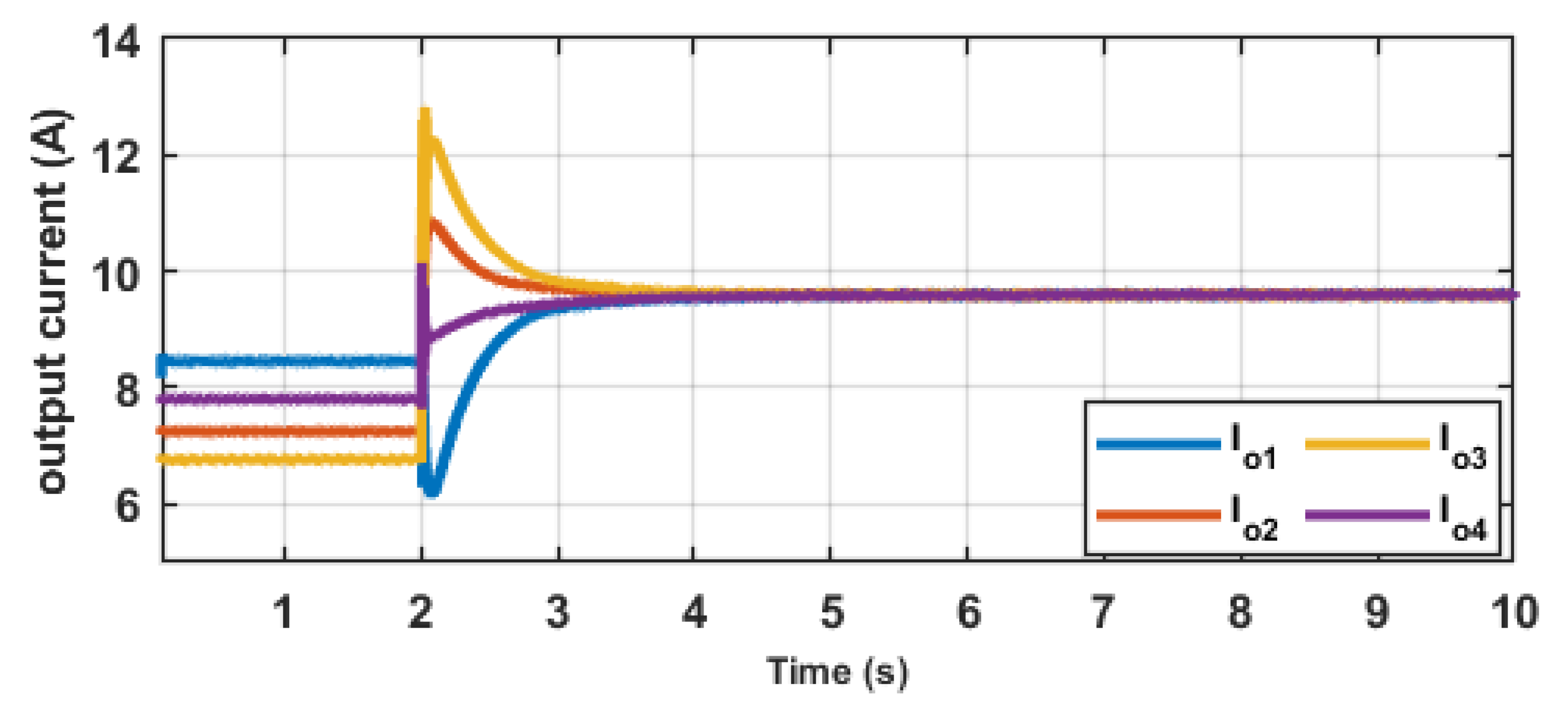
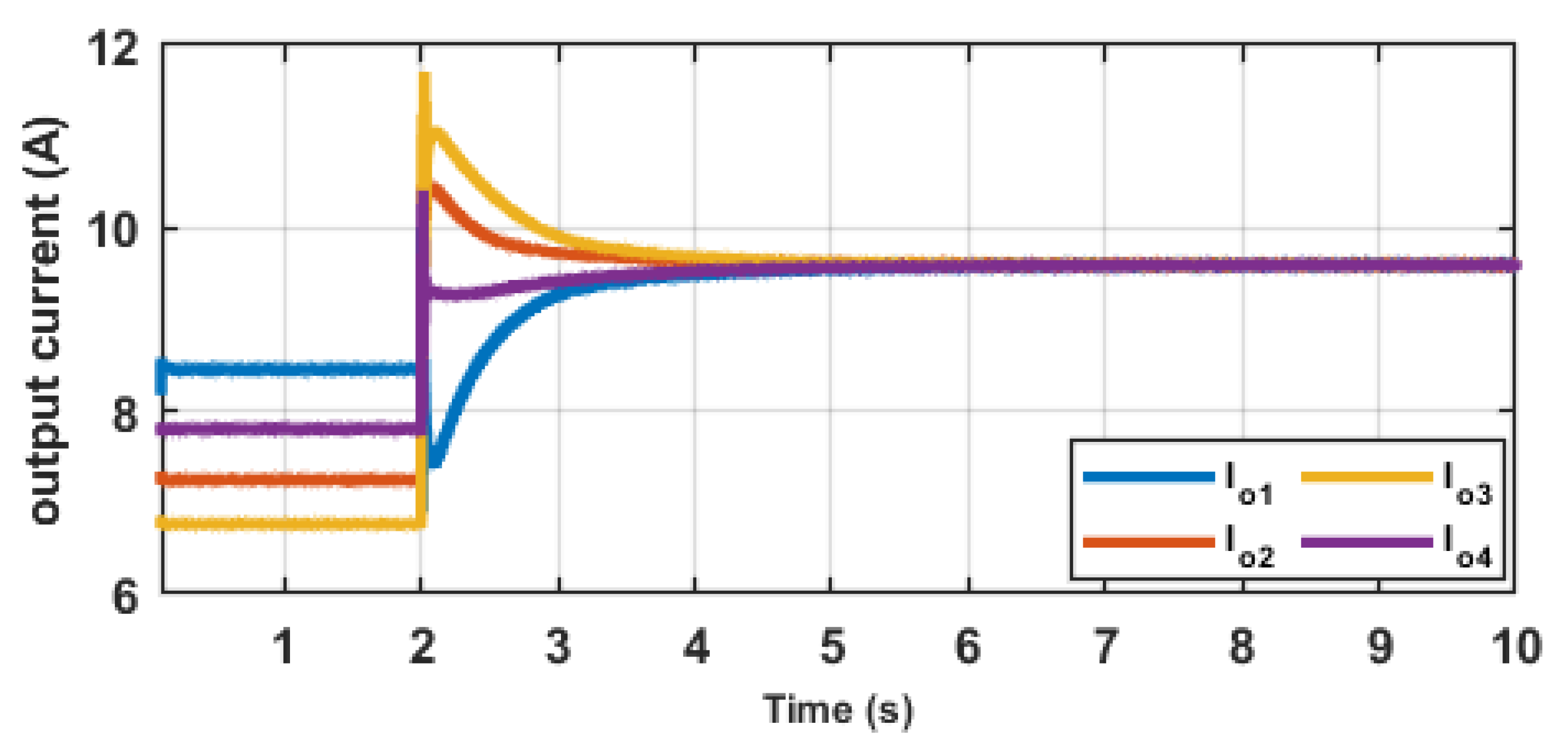
5.1. Test for Distributed Average Current Sharing and Voltage Regulation

In this scenario, the effectiveness of the proposed secondary controller to achieve the control objectives is investigated. Two information-sharing topologies are tested as shown in Figure 5. Topology A represents fully distributed communication; Topology B represents nearest neighbour distributed communication. It is important to mention that the communication is bidirectional, i.e., a i j = a j i . The total simulation time is 10 s. In Stage I, t [ 0 2 ) , only the primary controller in each DG is active. In Stage II, t ( 2 10 ] , the proposed secondary controllers in all the DGs are activated. The results of this scenario are shown in Figure 6, Figure 7, Figure 8 and Figure 9. In Figure 6a and Figure 7a, it is observed that the DC bus voltage (38 V) of the microgrid in Stage I is less than the rated DC bus voltage (48 V). This is due to the voltage deviation caused by the droop resistance and line impedance as given in (6). A similar result is observed in the output voltages of the DGs as shown in Figure 6b and Figure 7b. In Stage II, when the proposed fuzzy-based secondary controller is activated in the DGs, it is observed that the DC bus voltage of the microgrid rises to the rated value, and the output voltage of each DG rises above the rated value. The voltage rise above the rated value is a result of the line impedance between each DG and the DC bus that is governed by V i = V d c + R l i n e i I o i . The output current of each DG depicted in Figure 8 and Figure 9 show that DGs are unable to achieve average or consensus current sharing in Stage I. However, in Stage II, the objective of current sharing is achieved within 2 s of activation when all DGs have the same output current of 9.6 A in the microgrid.
By critically inspecting the voltage and current responses in this scenario, it is observed that the communication network using Topology A is characterized by higher magnitudes of transients when the secondary controller is activated compared to Topology B. Therefore, it can be surmised that the proposed fuzzy-based secondary control scheme can ensure current-sharing and voltage regulation objectives with the distributed property.
Table 3 presents the superiority of the proposed type-II fuzzy logic scheme for the defined control objectives compared to the traditional secondary control scheme with fixed gains [31]; it is seen that the traditional control scheme takes 2 s and 2.8 s to achieve the voltage regulation and current-sharing objectives, respectively. However, the proposed scheme achieves the voltage regulation objective in less than 0.1 s, and the current-sharing objective is approximately 2 s.

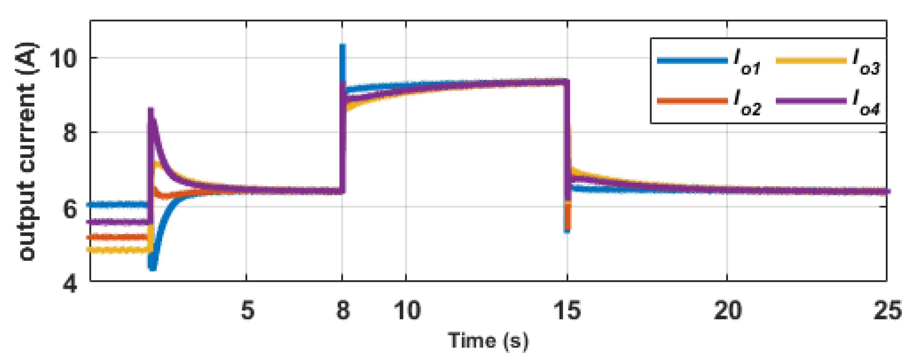
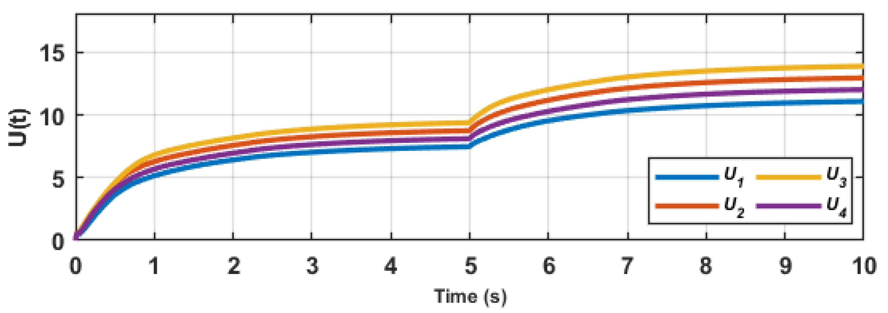
5.2. Performance of Proposed Controller during Load Change

In this scenario, the response of the proposed fuzzy-based distributed secondary controller during a change in load/demand is evaluated. Using the sparse communication network (Topology B) in the previous scenario, the simulation lasts for 25 s. In Stage I, t [ 0 2 ) , only the primary controllers in the DGs are active. In Stage II, t ( 2 8 ) , the proposed secondary controller in each DG is activated. In Stage III, t ( 8 15 ) , an additional load is connected at the DC bus. In Stage IV, t ( 15 25 ] , the load is disconnected from the microgrid. The results are presented in Figure 10, Figure 11 and Figure 12. The results for Stages I and II are similar to the previous scenario. The DC bus voltage and output voltages are shown in Figure 10. In Stage III, when the load is connected to the DC bus, there is a short voltage transient at the DC bus that is quickly eliminated to restore the bus voltage to 48 V. Likewise, when the load is disconnected from the microgrid in Stage IV, the DC bus voltage overshoot is dampened and maintained at the rated value to keep the system in the stable mode. It is generally observed that the output voltages of the DGs are higher than the rated voltage due to the effect of the line impedances between the DGs and the DC bus as previously described. The output current plots shown in Figure 11 reveal that the addition of the load increases the current generated by each DG, while the disconnection of the load causes a drop in the output. In Stages III and IV, the microgrid can ensure average current sharing among the DGs in both stages based on the control objectives of the proposed secondary controller. The output adjustment signal, U , of the proposed fuzzy-based secondary controller for each DG is shown in Figure 12. The adjustment signal eliminates the deviation caused by the action of the droop control as given in (11).

5.3. Performance under Communication Time Delay

In this scenario, a practical case of communication time delay among the proposed secondary controllers in each DG is considered to elucidate the robustness of the proposed control scheme. We consider various time delays between the secondary controllers using Topology A; a 12 = 100 ms, a 23 = 250 ms, and a 34 = 150 ms. The total simulation time is 10 s. In Stage I, t [ 0 5 ) , the primary and proposed secondary controllers in the DGs are active. In Stage II, t ( 5 10 ] , a load is switched on at the DC bus. The results of this scenario are shown in Figure 13 and Figure 14. From Figure 13a, it is observed that the output currents of the DGs have different starting times in Stage I due to the different time delays in the communication network of the microgrid, but the proposed fuzzy-based secondary controller can ensure consensus current sharing in < 1 s of operation. Similarly, in Stage II, when an additional load is switched on, the output current from each DG changes to meet the additional demand. The effect of time delay is noticed in the response of the output currents. However, the total current demand is equally shared among the DGs. The response of the DC bus voltage in this scenario is seen in Figure 13b. It is observed that the effect of the time delay is not conspicuous when compared to the output current response. This is because the voltage regulation objective is a global objective that requires control action from a minimum of one active DG, while the current-sharing objective is a consensus objective that requires the control action of all active DGs in the microgrid. The control action (adjustment signal) of the proposed distributed secondary controllers in the microgrid is shown in Figure 14. It is observed that each secondary controller reacts to meet the control objectives to ensure that the DC voltage is maintained at 48 V, and the load current is equally shared among the DGs.

6. Conclusions

This paper presents a new advanced distributed secondary control scheme for an islanded DC microgrid with multiple DGs. The proposed secondary control scheme is employed to compensate for the voltage deviation caused by the droop control and simultaneously ensure average current sharing amongst the DG. The type-II fuzzy logic scheme is employed to improve the performance of the proposed secondary controller. The inputs to the type-II fuzzy logic are the voltage deviation and current-sharing error. Its output is the secondary control parameter that modifies the voltage and current-sharing weights. Each DG has its type-II fuzzy-based secondary controller and communicates with other controllers to achieve the distributed approach. The Lyapunov stability method showed the required condition to ensure the stable operation of the proposed controller in the microgrid. The simulation results show that the proposed fuzzy-based secondary control scheme can efficiently ensure accurate voltage regulation and current sharing under plug-and-play, load change, and communication time delay scenarios. The proposed type-II fuzzy scheme can be applied to real-world DC microgrids to seamlessly solve the current sharing and voltage regulation issues. Further work may include the addition of nonlinear loads, different converter topologies, and the adoption of hybrid DGs.

Author Contributions

Conceptualization, A.A. and E.B.; methodology, A.A., E.B. and O.E.O.; software, A.A. and E.B.; validation, E.B., O.E.O. and I.E.D.; formal analysis, A.A. and E.B.; writing—original draft preparation, A.A. and E.B.; writing—review and editing, E.B., O.E.O. and I.E.D.; supervision, I.E.D.; project administration, I.E.D.; funding acquisition, I.E.D. All authors have read and agreed to the published version of the manuscript.

Funding

This research received no external funding and The APC was funded by DUT Smart Grid Research and DUT Directorate for Research and Postgraduate Supports.

Acknowledgments

The authors acknowledge the facility support from the Smart Grid Research Center at the Durban University of Technology.

Conflicts of Interest

The authors declare no conflict of interest.

References

  1. Aluko, A.O.; Dorrell, D.G.; Carpanen, R.P.; Ojo, E.E. Heuristic Optimization of Virtual Inertia Control in Grid-Connected Wind Energy Conversion Systems for Frequency Support in a Restructured Environment. Energies 2020, 13, 564. [Google Scholar] [CrossRef] [Green Version]
  2. Aluko, A.; Musumpuka, R.; Dorrell, D. Cyberattack-Resilient Secondary Frequency Control Scheme for Stand-Alone Microgrids. IEEE Trans. Ind. Electron. 2022. [Google Scholar] [CrossRef]
  3. Kumar, J.; Agarwal, A.; Singh, N. Design, operation and control of a vast DC microgrid for integration of renewable energy sources. Renewable Energy Focus 2020, 34, 17–36. [Google Scholar] [CrossRef]
  4. Al-Ismail, F.S. DC microgrid planning, operation, and control: A comprehensive review. IEEE Access 2021, 9, 36154–36172. [Google Scholar] [CrossRef]
  5. Aluko, A.O.; Dorrell, D.G.; Ojo, E.E. Inertia Emulation in Low Inertia Power Systems Considering Frequency Measurement Effects. In Proceedings of the 2021 International Conference on Electrical, Computer and Energy Technologies (ICECET), Cape Town, South Africa, 9–10 December 2021; pp. 1–6. [Google Scholar] [CrossRef]
  6. Abhishek, A.; Ranjan, A.; Devassy, S.; Verma, B.K.; Ram, S.K.; Dhakar, A.K. Review of hierarchical control strategies for DC microgrid. IET Renew. Power Gener. 2020, 14, 1631–1640. [Google Scholar] [CrossRef]
  7. Fang, J.; Shuai, Z.; Zhang, X.; Shen, X.; Shen, Z.J. Secondary power sharing regulation strategy for a dc microgrid via maximum loading factor. IEEE Trans. Power Electron. 2019, 34, 11856–11867. [Google Scholar] [CrossRef]
  8. Nahata, P.; La Bella, A.; Scattolini, R.; Ferrari-Trecate, G. Hierarchical control in islanded DC microgrids with flexible structures. IEEE Trans. Control. Syst. Technol. 2020, 29, 2379–2392. [Google Scholar] [CrossRef]
  9. Peyghami, S.; Mokhtari, H.; Loh, P.C.; Davari, P.; Blaabjerg, F. Distributed primary and secondary power sharing in a droop-controlled LVDC microgrid with merged AC and DC characteristics. IEEE Trans. Smart Grid 2017, 9, 2284–2294. [Google Scholar] [CrossRef] [Green Version]
  10. Federico, I.; Jose, E.; Luis, F. Master–slave DC droop control for paralleling auxiliary DC/DC converters in electric bus applications. IET Power Electron. 2017, 10, 1156–1164. [Google Scholar] [CrossRef]
  11. Wu, D.; Tang, F.; Dragicevic, T.; Guerrero, J.M.; Vasquez, J.C. Coordinated control based on bus-signaling and virtual inertia for islanded DC microgrids. IEEE Trans. Smart Grid 2015, 6, 2627–2638. [Google Scholar] [CrossRef] [Green Version]
  12. Cupelli, M.; Monti, A.; De Din, E.; Sulligoi, G. Case study of voltage control for MVDC microgrids with constant power loads-Comparison between centralized and decentralized control strategies. In Proceedings of the 2016 18th Mediterranean Electrotechnical Conference (MELECON), Lemesos, Cyprus, 18–20 April 2016; pp. 1–6. [Google Scholar]
  13. Xu, Q.; Xiao, J.; Hu, X.; Wang, P.; Lee, M.Y. A decentralized power management strategy for hybrid energy storage system with autonomous bus voltage restoration and state-of-charge recovery. IEEE Trans. Ind. Electron. 2017, 64, 7098–7108. [Google Scholar] [CrossRef]
  14. Amiri, H.; Markadeh, G.A.; Dehkordi, N.M.; Blaabjerg, F. Fully decentralized robust backstepping voltage control of photovoltaic systems for DC islanded microgrids based on disturbance observer method. ISA Trans. 2020, 101, 471–481. [Google Scholar] [CrossRef] [PubMed]
  15. Ge, X.; Han, H.; Xiong, W.; Su, M.; Liu, Z.; Sun, Y. Locally-distributed and globally-decentralized control for hybrid series-parallel microgrids. Int. J. Electr. Power Energy Syst. 2020, 116, 105537. [Google Scholar] [CrossRef]
  16. Peng, J.; Fan, B.; Duan, J.; Yang, Q.; Liu, W. Adaptive decentralized output-constrained control of single-bus DC microgrids. IEEE/CAA J. Autom. Sin. 2019, 6, 424–432. [Google Scholar] [CrossRef]
  17. Gao, F.; Kang, R.; Cao, J.; Yang, T. Primary and secondary control in DC microgrids: A review. J. Mod. Power Syst. Clean Energy 2019, 7, 227–242. [Google Scholar] [CrossRef] [Green Version]
  18. Armghan, H.; Yang, M.; Wang, M.; Ali, N.; Armghan, A. Nonlinear integral backstepping based control of a DC microgrid with renewable generation and energy storage systems. Int. J. Electr. Power Energy Syst. 2020, 117, 105613. [Google Scholar] [CrossRef]
  19. Chen, X.; Shi, M.; Zhou, J.; Chen, Y.; Zuo, W.; Wen, J.; He, H. Distributed cooperative control of multiple hybrid energy storage systems in a DC microgrid using consensus protocol. IEEE Trans. Ind. Electron. 2020, 67, 1968–1979. [Google Scholar] [CrossRef]
  20. Guo, F.; Xu, Q.; Wen, C.; Wang, L.; Wang, P. Distributed secondary control for power allocation and voltage restoration in islanded DC microgrids. IEEE Trans. Sustain. Energy 2018, 9, 1857–1869. [Google Scholar] [CrossRef]
  21. Dong, M.; Li, L.; Nie, Y.; Song, D.; Yang, J. Stability analysis of a novel distributed secondary control considering communication delay in DC microgrids. IEEE Trans. Smart Grid 2019, 10, 6690–6700. [Google Scholar] [CrossRef]
  22. Guo, F.; Wang, L.; Wen, C.; Zhang, D.; Xu, Q. Distributed voltage restoration and current-sharing control in islanded DC microgrid systems without continuous communication. IEEE Trans. Ind. Electron. 2020, 67, 3043–3053. [Google Scholar] [CrossRef]
  23. Gheisarnejad, M.; Khooban, M.H.; Dragičevié, T. The future 5G network-based secondary load frequency control in shipboard microgrids. IEEE J. Emerg. Sel. Top. Power Electron. 2020, 8, 836–844. [Google Scholar] [CrossRef]
  24. Shan, Y.; Hu, J.; Chan, K.W.; Islam, S. A unified model predictive voltage and current control for microgrids with distributed fuzzy cooperative secondary control. IEEE Trans. Ind. Inform. 2021, 17, 8024–8034. [Google Scholar] [CrossRef]
  25. Deshmukh, R.R.; Ballal, M.S.; Suryawanshi, H.M. A fuzzy logic based supervisory control for power management in multibus DC microgrid. IEEE Trans. Ind. Appl. 2020, 56, 6174–6185. [Google Scholar] [CrossRef]
  26. Farsizadeh, H.; Gheisarnejad, M.; Mosayebi, M.; Rafiei, M.; Khooban, M.H. An intelligent and fast controller for DC/DC converter feeding CPL in a DC microgrid. IEEE Trans. Circuits Syst. II Express Briefs 2020, 67, 1104–1108. [Google Scholar] [CrossRef]
  27. Khooban, M.H.; Gheisarnejad, M.; Vafamand, N.; Boudjadar, J. Electric vehicle power propulsion system control based on time-varying fractional calculus: Implementation and experimental results. IEEE Trans. Intell. Veh. 2019, 4, 255–264. [Google Scholar] [CrossRef]
  28. Aluko, A.O.; Carpanen, R.P.; Dorrell, D.G.; Ojo, E.E. Robust State Estimation Method for Adaptive Load Frequency Control of Interconnected Power System in a Restructured Environment. IEEE Syst. J. 2021, 15, 5046–5056. [Google Scholar] [CrossRef]
  29. Liang, Q.; Mendel, J.M. Interval type-2 fuzzy logic systems: Theory and design. IEEE Trans. Fuzzy Syst. 2000, 8, 535–550. [Google Scholar] [CrossRef] [Green Version]
  30. Zammit, D.; Staines, C.S.; Apap, M.; Micallef, A. Overview of Buck and Boost converters modelling and control for stand-alone DC microgrid operation. In Proceedings of the Offshore Energy &Storage Symposium (OSES 2016), Valletta, Malta, 13–15 July 2016; Volume 2294, pp. 2284–2294. [Google Scholar]
  31. Liu, X.K.; Wang, Y.W.; Lin, P.; Wang, P. Distributed supervisory secondary control for a DC microgrid. IEEE Trans. Energy Convers. 2020, 35, 1736–1746. [Google Scholar] [CrossRef]
Figure 1. Power system model of a DC microgrid.
Energies 15 03988 g001
Figure 2. Type-II fuzzy logic system.
Energies 15 03988 g002
Figure 3. Proposed fuzzy-based distributed secondary control scheme.
Energies 15 03988 g003
Figure 4. FOU of type-II fuzzy logic membership functions.
Energies 15 03988 g004
Figure 5. (a) Topology A; (b) Topology B.
Energies 15 03988 g005
Figure 6. (a) DC bus voltage; (b) output voltage of DGs using Topology A.
Energies 15 03988 g006
Figure 7. (a) DC bus voltage; (b) output voltage of DGs using Topology B.
Energies 15 03988 g007
Figure 8. Output currents of DGs using Topology A.
Energies 15 03988 g008
Figure 9. Output currents of DGs using Topology B.
Energies 15 03988 g009
Figure 10. (a) DC bus voltage; (b) output voltage of DGs.
Energies 15 03988 g010
Figure 11. Output currents of DGs.
Energies 15 03988 g011
Figure 12. Output of proposed distributed secondary controller.
Energies 15 03988 g012
Figure 13. (a) Output current of DGs; (b) DC bus voltage under different communication time delays.
Energies 15 03988 g013
Figure 14. Output of proposed distributed secondary controller under different communication time delays.
Energies 15 03988 g014
Table 1. Table of fuzzy rules.
Δ V dc
Δ I o i PLPSZNSNL
PLLLMMM
PSLLSMM
ZLSSSL
NSMMSLL
NLMMMLL
Table 2. DC microgrid Parameters.
ParameterSymbolValue
Rated Bus Voltage V d c 48 V
Source Voltage V s 100 V
Sampling Frequency f s 10 kHz
Filter Inductance and Capacitance L , C 1 mH, 235 μ F
Line Resistance R l i n e , i i = 1 , 4 0.5   Ω , 0.2   Ω , 0.6   Ω , 0.3   Ω
Total Load R L o a d j j = 1 , 3 12   Ω
Primary and Secondary Controls
Inner Current Controller K p , K i 0.05, 148
Inner Voltage Control K p , K i 0.248, 36
Droop resistance R d i i = 1 , 4 1   Ω
Voltage Deviation weights α 1.25
Current Deviation weights β 7.5
Table 3. Proposed scheme with other control schemes.
Control ObjectiveTraditional Secondary ControlProposed Type-II Fuzzy Logic Control
Objective 12 s 0.1 s
Objective 22.8 s2 s
Publisher’s Note: MDPI stays neutral with regard to jurisdictional claims in published maps and institutional affiliations.

