Article

Experimental and Theoretical Study of Surge Behavior in a Boil-Off Gas Centrifugal Compressor on an LNG Carrier

1
Department of Naval Architecture and Offshore Engineering, Dong-A University, 37 Nakdong-daero 550 Beon-gil, Saha-gu, Busan 49315, Korea
2
Department of Chemical Science and Engineering, Kyungpook National University, 80 Daehak-ro, Buk-gu, Daegu 41566, Korea
3
Department of Aerospace Engineering, Republic of Korea Air Force Academy, 635 Danjae-ro, Sangdang-gu, Cheongju 28187, Korea
*
Author to whom correspondence should be addressed.
Energies 2022, 15(11), 4002; https://doi.org/10.3390/en15114002
Submission received: 9 May 2022 / Revised: 25 May 2022 / Accepted: 26 May 2022 / Published: 29 May 2022

Abstract

:
In this study, we conducted experiments and numerical analysis on a 270 kW industrial-scale centrifugal compressor used in the fuel supply system of an LNG carrier in order to improve the lumped-parameter surge model by considering the viscosity in the pipeline and to confirm whether the improved model would be applicable. The steady and unsteady compressor performance curves were constructed using measurements and predictions, respectively. The flow through the pipeline was assumed to be both steady and unsteady, and each governing equation under the assumptions was derived in accordance with the lumped-parameter model. In the steady flow case, the surge behavior of the modified model was in a good agreement with the lumped-parameter model at surge parameter B = 4.8716. In the unsteady flow case, however, the modified model showed a deviation from the lumped-parameter model, and the simulation from the modified model described the surge behavior 5% more accurately than the lumped-parameter model. Through experiments and numerical analysis, this study showed that the present models are useful and applicable for describing the surge behavior of an industrial-scale single-stage centrifugal compressor.

1. Introduction

Gas compressors are used in various places all over the world. These include aircraft propulsion with turbojet engines, offshore and onshore power plants with gas turbines, marine propulsion with turbo-chargers in main engines, pressurization of fluids in the oil and gas industry, and natural gas transport in pipelines [1]. Beginning in the 1960s, centrifugal compressors have been popular thanks to their improved efficiency, low maintenance costs, and compact size [2]. In particular, they are used for boil-off gas treatment in more than 500 LNG carriers currently in operation around the world [3].
The useful operation range of centrifugal compressors is often limited at low mass flow by fluid dynamic instabilities, typically, a surge or a rotating stall [4,5]. A rotating stall can degrade compressor performance, and the surge can destroy the compressor’s structure in just a few seconds. Accordingly, it is important to analyze the mechanism for the rotating stall and surge for efficient working range, control, and safety. The generation mechanism for the rotating stall and surge of a centrifugal compressor was analyzed by Sundström et al. [6]. In addition, several researchers have analyzed the mechanism with a variable vaned diffuser [7] and with a vaneless diffuser [8], and the acoustic signature [9] has been studied as well.
A surge is an unstable operation and a one-dimensional instability. If the flow is reduced to below the surge point compressor operation becomes unstable, resulting in periodic pressure and flow oscillations throughout the overall system of compressor. The flow may change its magnitude in the forward direction alone or change its direction between forward and backward, with a complete momentary stop in between. A surge is characterized by a limit cycle oscillation that affects the power and axial rotor thrust as well as the oscillation, and in the case of an uncooled compressor will steadily increase the temperature level unless stopped by an automatic trip [4,5,6]. In particular, it results in a critical loss of performance and efficiency, as large fluctuations in pressure and mass flow rate can make the chemical or oil and gas processing system unstable, which is connected to the compression system. Surges can generally be classified into two types, mild and deep. Mild surges have no reverse flow, while deep surges have a negative mass flow rate [10].
On the contrary, a rotating stall results from local flow separation and reversal in the impeller or in regions of stagnant flow. It shows the instability characteristics of two-dimensional direction and local regions. While compressor operation remains stable, a stall can result in a large drop in performance and efficiency. The annulus-averaged mass flow across the compressor is steady, though circumferentially non-uniform [4,5,6].
Many studies have been conducted on surges and rotating stalls in the field of gas compressors. Emmons et al. [11] derived one of the first models for the dynamic behavior of compression systems, developing a linearized compression model through an analogy between a Helmholtz resonator and the small oscillations associated with surge initiation. Great progress in this field was made by Greitzer [12,13], who researched and developed a nonlinear lumped-parameter model for axial compressors. Although it was based on the linear analysis of Emmons et al. [11], the Greitzer model was the first model to account for the large amplitude oscillations during the surge period. The Greitzer model has been the most widely used dynamic model in this field. Hansen et al. [14] showed that the Greitzer model can be used to simulate surge behavior in a centrifugal compressor system. Moreover, Fink et al. [15] extended the model to centrifugal compressors with a variable rotor speed. Moore and Greitzer [16,17] developed their model of compression system dynamics. This model was developed by coupling two-dimensional unsteady flow descriptions to the Greitzer model in order to capture both surge and stall phenomena. Macdougal and Elder [18] derived a model similar to the Greitzer model. Assuming the duct flow as a compressible flow, their model was able to deal with non-ideal gases and varying gas compositions.
In spite of the theoretical development of the various surge models, most experiments have been performed with laboratory-scale installations [19,20,21]. Furthermore, in most cases it is difficult to simulate the exact surge cycle compared with actual ones using parameters from the geometrical data of the system. Thus, many researchers have had difficulty simulating the surge cycle to predict the actual behavior by varying the compressor duct length and plenum volume [21].
The purposes of this paper are, first, to modify the Greitzer model for a compression system, and second, to confirm whether the modified Greitzer model is applicable. The target system is a 270 kW industrial-scale single-stage centrifugal compressor used in the fuel supply system of an LNG ship. In order to improve the conventional Greitzer model, the viscosity effect in the inlet pipeline under two views is considered and demonstrated through experiments and numerical analysis, and experiments are conducted to validate the proposed models for the industrial-scale single-stage centrifugal compressor system.

2. Surge System Modeling

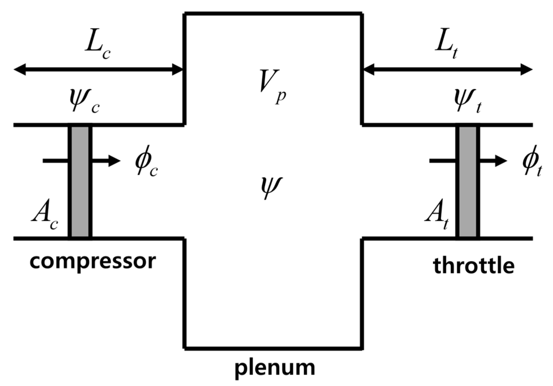
2.1. Conventional Greitzer Model

Greitzer [12,13] developed a nonlinear mathematical model of a transient compression system to describe the large amplitude oscillations encountered during a surge period, which were not explained by the linearized compression model by Emmons et al. [11]. The Greitzer equivalent compression system is shown in Figure 1. The compression system consists of the compressor internals, a throttle valve, the plenum volume, and other pipelines. It is assumed that the gas flowing through the compression system is incompressible, the density is equal to the ambient density, the gas velocity in the plenum is negligible, the static pressure is uniform throughout the plenum, and the process in the plenum is considered as an isentropic process [12,13]. The equations of the compressor system model derived by Greitzer are as follows:
d ϕ c d t ˜ = B ( ψ c ψ )
d ϕ t d t ˜ = B G ( ψ ψ t )
d ψ d t ˜ = 1 B ( ϕ c ϕ t )
d ψ c d t ˜ = 1 τ ˜ ( ψ c . s s ψ c )
where the system parameters are provided by Equations (5)–(9).
B = U 2 ω H L c
G = L t / A t L c / A c
τ ˜ = π R N L c B
ω H = a A c V p L c
t ˜ = t ω H
The dimensionless governing equations, that is, Equations (1)–(4), are derived from momentum balance and mass balance [18]. Time is nondimensionalised by the Helmholtz frequency, ω H , of the compressor inlet duct and the plenum volume. The parameter B has physical significance in the compressor model; in other words, the transient response of the compression system is strongly dependent on it. Equations (1)–(4) are nonlinear mathematical models for the unsteady behavior of the compressor system, such that the numerical analysis is adopted. Equations (1)–(4) are solved by a fourth-order Runge–Kutta method, with the initial condition found through experiments. The geometrical data of the compression system are indicated in Table 1. Time lag in revolutions, N, in Equation (7), is set to 0 because the B parameter is large.
The definition of the nondimensional pressure rise and mass flow rate are as follows:
ψ c = Δ P 1 2 ρ U 2
ϕ c = C x U

2.2. Proposed Model

It is clear that the surge cycle of the Greitzer model and the measured surge cycle do not completely coincide. Therefore, many researchers have used the Greitzer model to roughly predict the surge cycle of the test compressor. This section shows how much influence the viscosity in the inlet pipeline has on the surge cycle. Moreover, the flow in the pipeline is assumed to be both steady flow and unsteady flow. In the steady flow, the Darcy–Weisbach equation was employed; in the unsteady flow, the Oscillating pipe flow concept was applied.

2.2.1. Steady Flow Case

By employing the Darcy–Weisbach equation, the conventional lumped-parameter model was modified and the contribution of the viscosity in the inlet pipeline was found. It was assumed that the flow is fully developed, steady, and incompressible. The Darcy–Weisbach equation is as follows; the friction factor, f, is calculated by Colebrook equation.
h L = f L D C x 2 2 g
The dimensional momentum equation of the inlet pipeline can be written as follows:
L c d m ˙ · · · · c d t = A c ( Δ P c Δ P ) F f r i c t i o n
F f r i c t i o n = A w f L c D ρ C x 2 2 g
Equation (13) can be nondimensionalized:
d ϕ c d t ˜ = B ( ψ c ψ ) π 4 L c f C x ω H A w ϕ c
Equation (15) is a modified momentum equation describing the dynamics of the inlet pipeline. Therefore, Equations (2)–(4) and (15) describe the dynamics of the compressor system. When solving these equations, the Moody chart is used, and ε/D, i.e., the relative pipe roughness, is 0.00018.

2.2.2. Unsteady Flow Case

Here, the flow through the inlet pipeline is assumed to be the unsteady fully developed flow, and the oscillating flow in a circular pipe is derived according to Meulenman [22], Samaan [23], and Uchida [24]. A brief overview of the key factors is presented here.
The circular coordinate is applied, and the x-axis is taken along the axis of the pipe from the entrance section and the r-axis along the radius of the pipe normal to the x-axis; u is the velocity along the x-axis. Based on Navier–Stokes equations, Equation (16) is obtained:
u t = 1 ρ p x + ν 1 r [ r ( r u r ) ]   w i t h   u = 0   a t   r = R
In the oscillating pipe flow, the pressure gradient becomes
1 ρ p x = K sin ( n t )
where K is a constant and n = 2 π f .
For simplicity of calculation, a complex form (Equation (17)) is introduced as follows:
1 ρ p x = i K e i n t ,   u ( r , t ) = U ( r ) e i n t
Substituting Equation (18) into Equation (16), the differential equation is as follows:
r 2 2 U ( r ) r 2 + r U ( r ) r r 2 i n ν U ( r ) = i n ν r 2
The solution is provided by
U ( r ) = C 1 J 0 ( α i r ) + C 2 Y 0 ( α i r )
where C 1 and C 2 are coefficients, J 0 and Y 0 are the first and second solutions of the Bessel function of zero order, respectively, and α i = R n ν i .
The boundary conditions at the wall are u = 0   a t   r = ± R . By substituting the boundary conditions into the equation, C 1 and C 2 can be determined. The last form of the solution is provided by
u ( r , t ) = K n e int ( 1 J 0 ( r R α i ) J 0 ( α i ) )
The mass flow rate and the wall shear stress are as follows:
m ( t ) = i ρ K π R 4 α i 2 ν { 1 2 α i J 1 ( α i ) J 0 ( α i ) } e i n t ,   τ w = i ρ K R α i J 1 J 0 e i n t
By solving Equation (16), the following momentum equation is obtained:
d m ˙ d t = A c L c ( Δ P Δ P c ) + 2 π R τ w
As it was impossible to obtain the exact solutions, the solution was approximated. For very low frequencies (n → 0), a quasi-steady velocity is obtained:
u ( r , t ) = i K 4 ν ( R 2 r 2 ) e i n t
The quasi-steady mass flow is as follows:
m ( t ) = i ρ K π R 4 8 ν e i n t
The quasi-steady wall shear stress is determined with Equations (23)–(25):
τ w = 4 ν π R 3 m ˙
Substituting Equation (26) into Equation (23), Equation (23) is introduced as follows:
d m ˙ d t = A c L c ( Δ P Δ P c ) 8 ν R 2 m ˙
Equation (27) can be nondimensionalized as follows:
d ϕ d t ˜ = B ( ψ c ψ ) 32 ν D 2 ω H ϕ
Equation (28) is a modified momentum equation. In the Greitzer model, Equation (1) is replaced with Equation (28), and Equations (2)–(4) and (28) are solved by the fourth-order Runge–Kutta method.

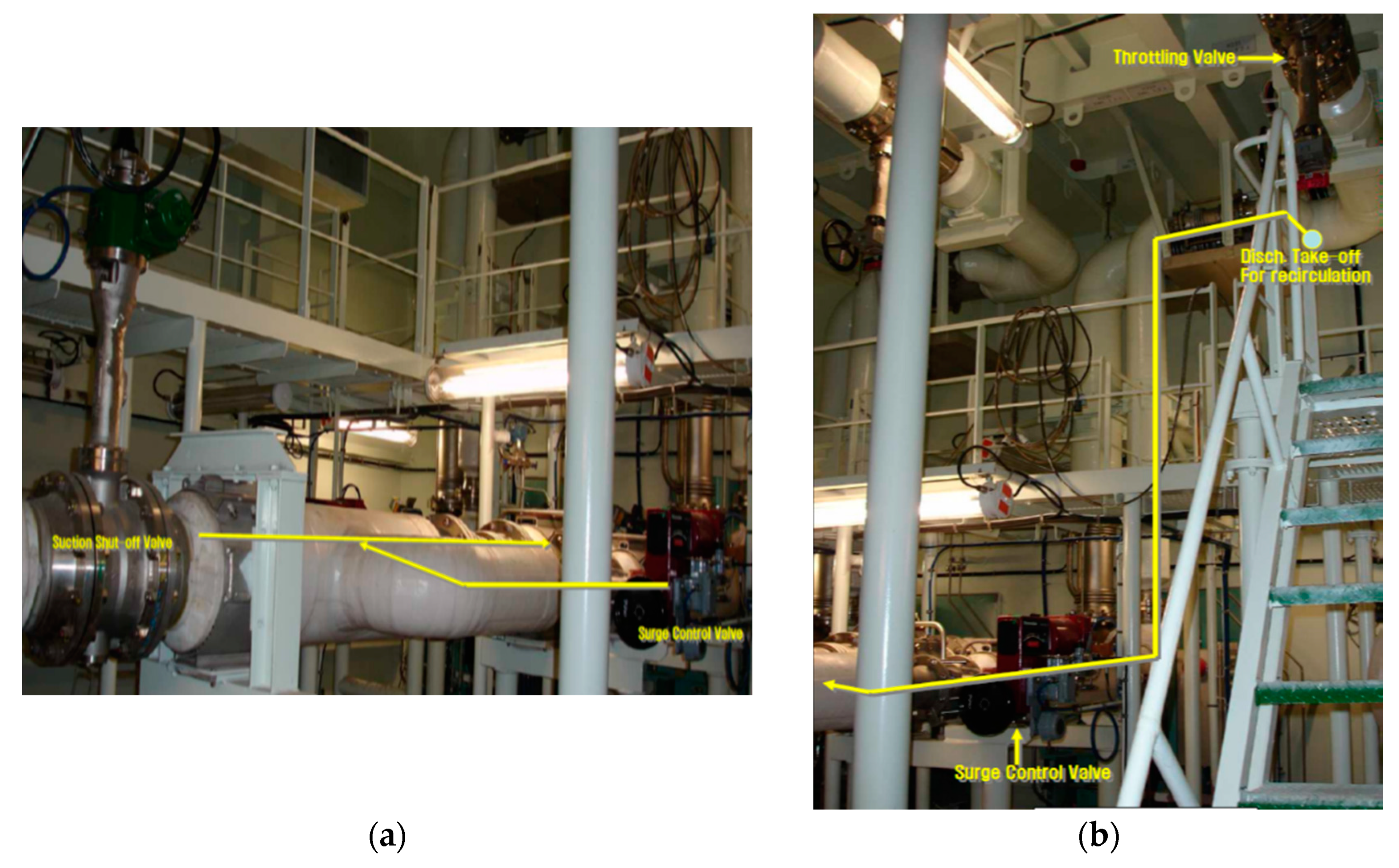
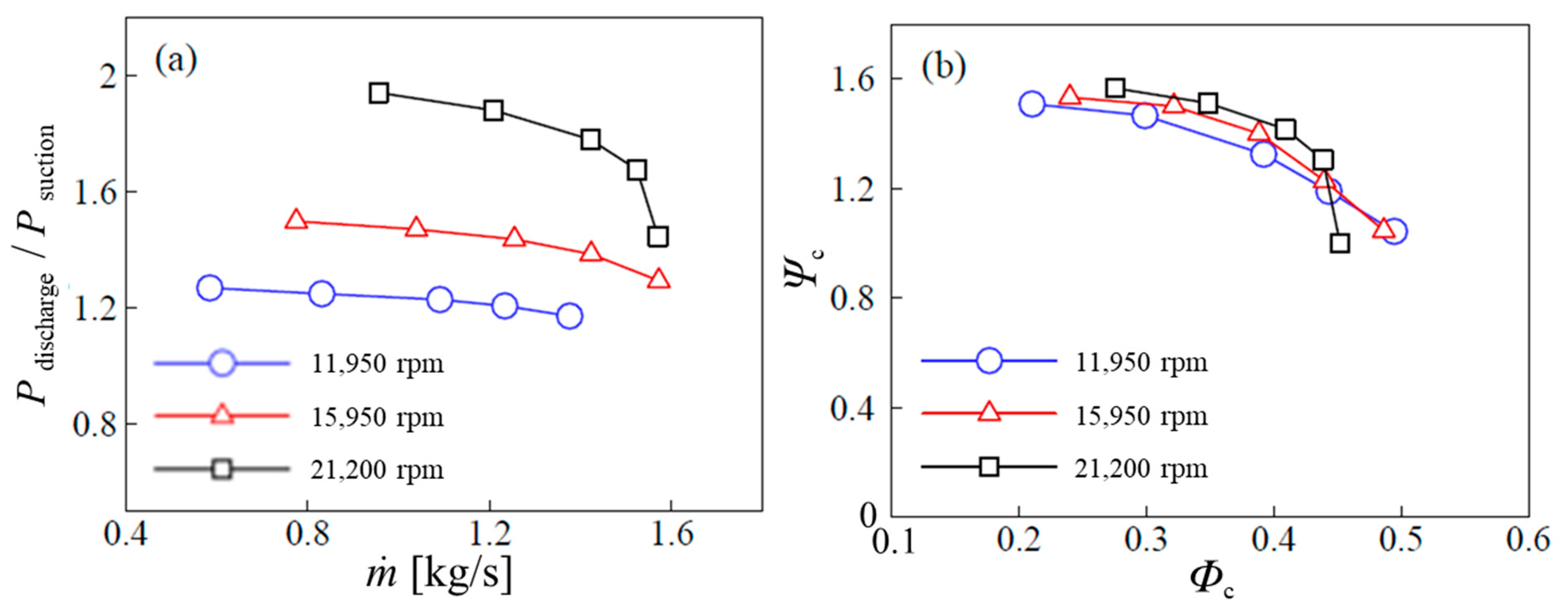
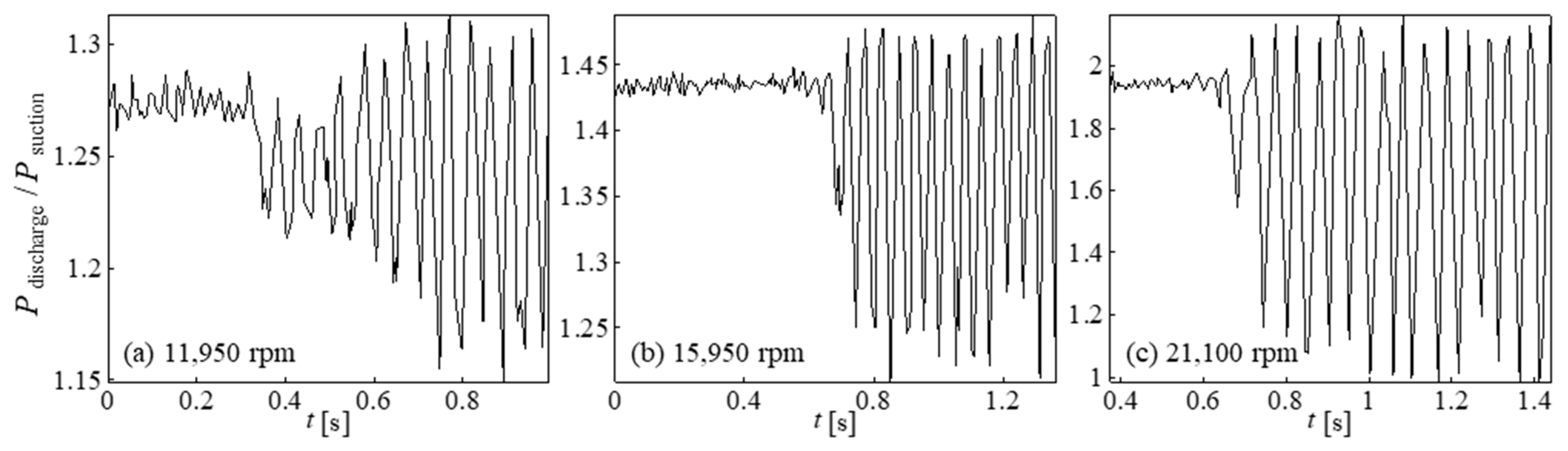
3. Experimental Setup

An industrial scale compression system was used to study a surge in a large-scale centrifugal compressor driven by a 270 kW electric motor, which can control the speed from 12,000 to 24,000 rpm. The compression system consists of an inlet pipeline, a single stage centrifugal compressor (Cryostar, C-300/45 L/D), an outlet pipe-line, and a throttle valve, as shown in Figure 2. The compressor is a single-stage centrifugal machine with an impeller diameter of 270 mm, as shown in Figure 3a, and the compression system is exposed to the ambient air at the compressor inlet and outlet. The design performance of the compressor ranges up to a pressure ratio of 1.85 with a maximum of 8500 m3/h. A set of variable inlet guide vanes is fitted, as shown in Figure 3b, although it was fixed at 0° during the experiment.
Figure 2 and Table 2 show the location and specifications of the instruments used for the surge measurements, respectively. To determine the performance of the compressor, three-wire Pt-100 s pressure sensors (Rosemount 2088 smart pressure transmitter) and a plate orifice (Sofameca) with a differential pressure sensor were used. The compressor discharge line was throttled using a butterfly valve (Westad Cryoseal Class 150 DN250). The date was acquired using a Honewyell C-200 distributed control system, which is widely used in large onshore chemical plants and offshore plants.
The steady-state performance of the compressor at 11,950 rpm, 15,950 rpm, and 21,100 rpm was measured by slowly closing the throttle valve (Figure 4). For the deep surge model, the performance of the compressor was only measured at 15,950 rpm because the system was operationally limited in each measurement. Figure 5a shows the performance curve, the pressure ratio vs. the mass flow rate, for the three speeds. The nondimensional compressor performance curve is shown in Figure 5b, and the performance curves for each speed nearly coincide. The densities predicted from the pressures and temperatures were applied for the nondimensionalization. The difference between the predicted density and real density was the most dominant where the curves did not match perfectly.
To describe the unsteady part of the compressor performance curve, the cubic polynomial of Moore and Greitzer [16] was used. Figure 6a shows the fitted curves based on the measured steady-state performance for the three speeds. In Figure 6b, the unsteady part was approximated using the cubic polynomial from Moore and Greitzer [16].

4. Results and Discussion

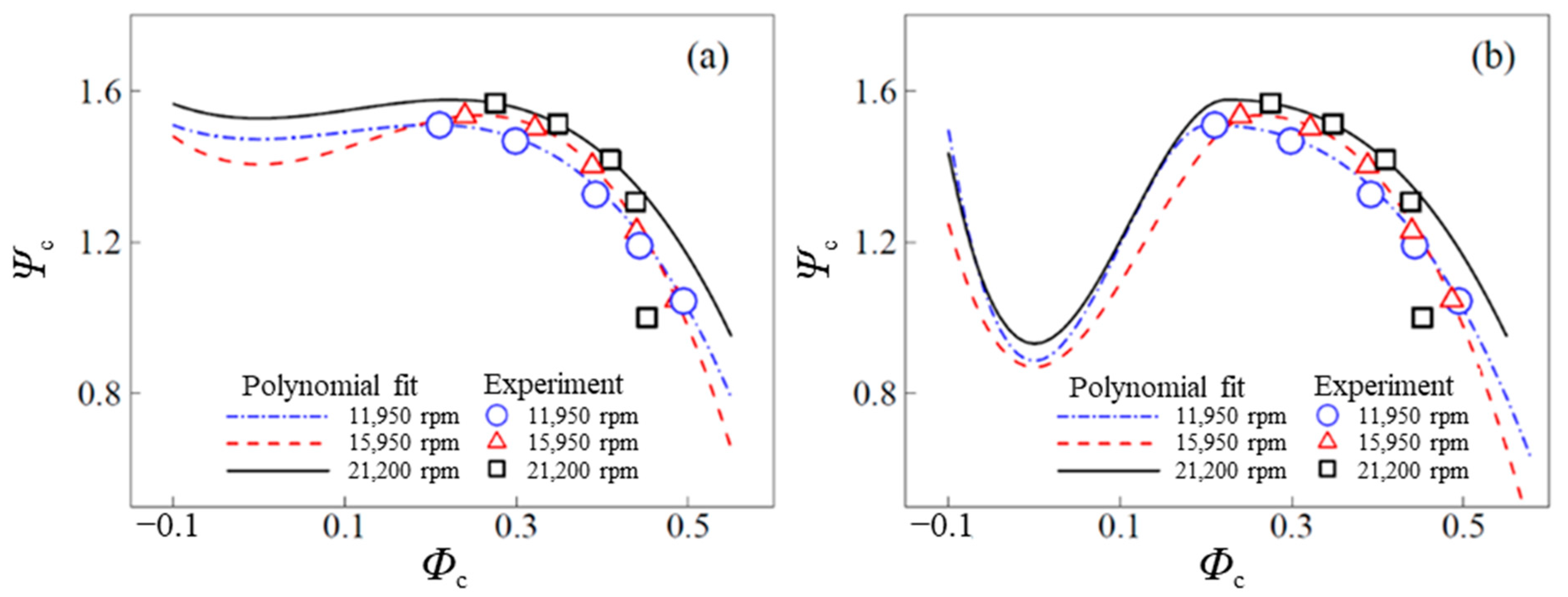
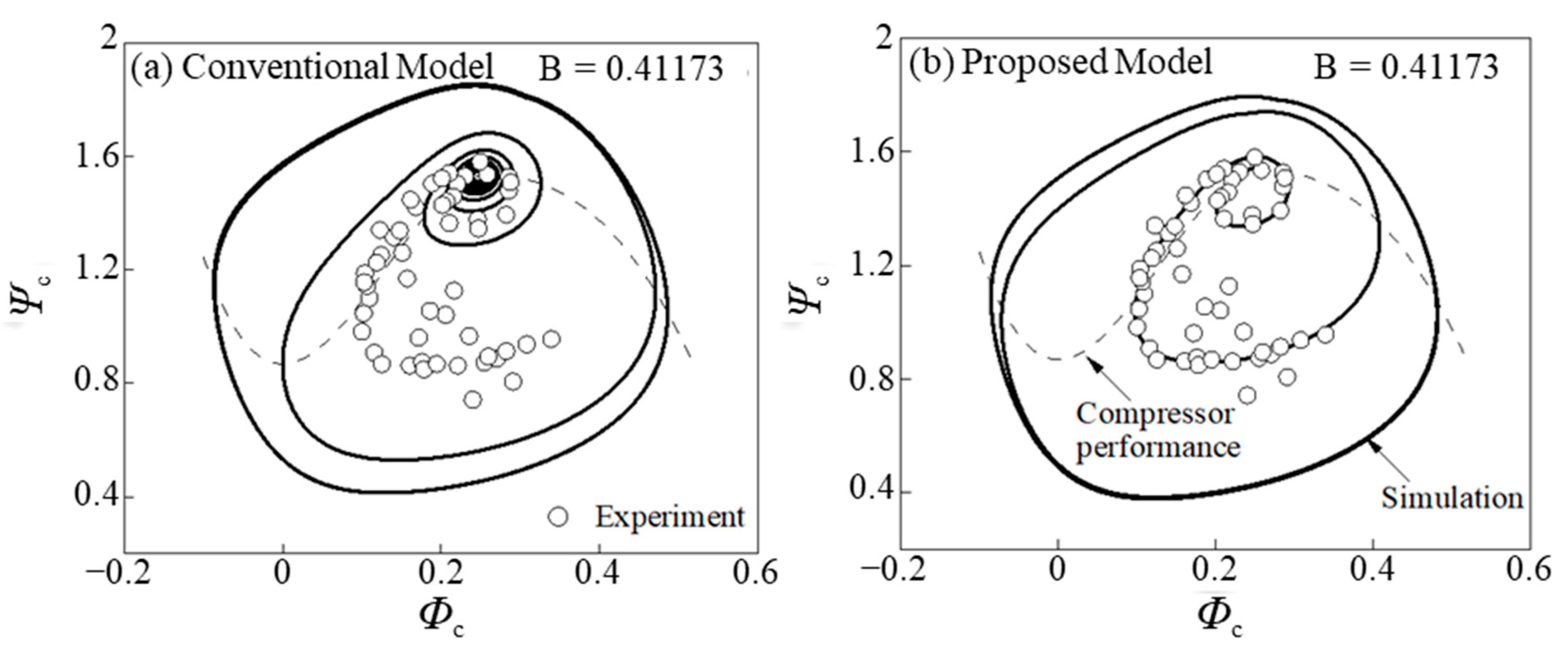
4.1. Conventional Greitzer Model
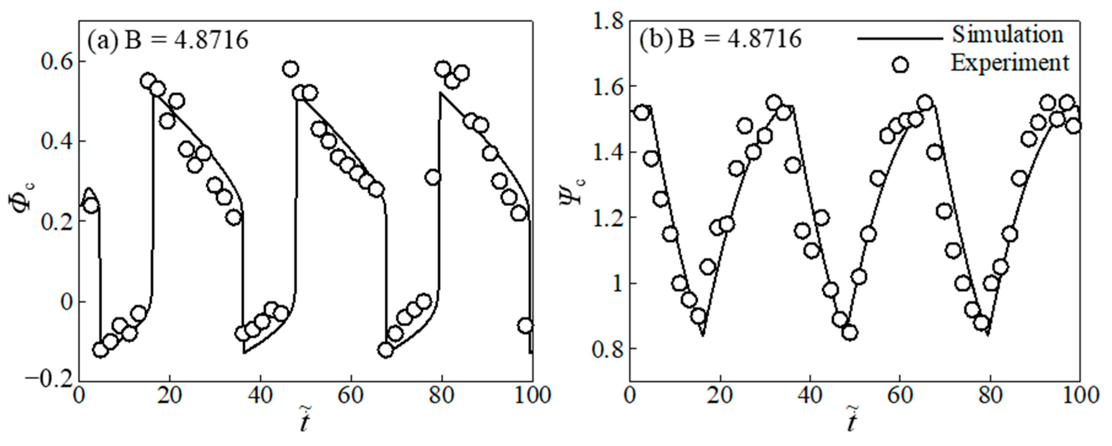
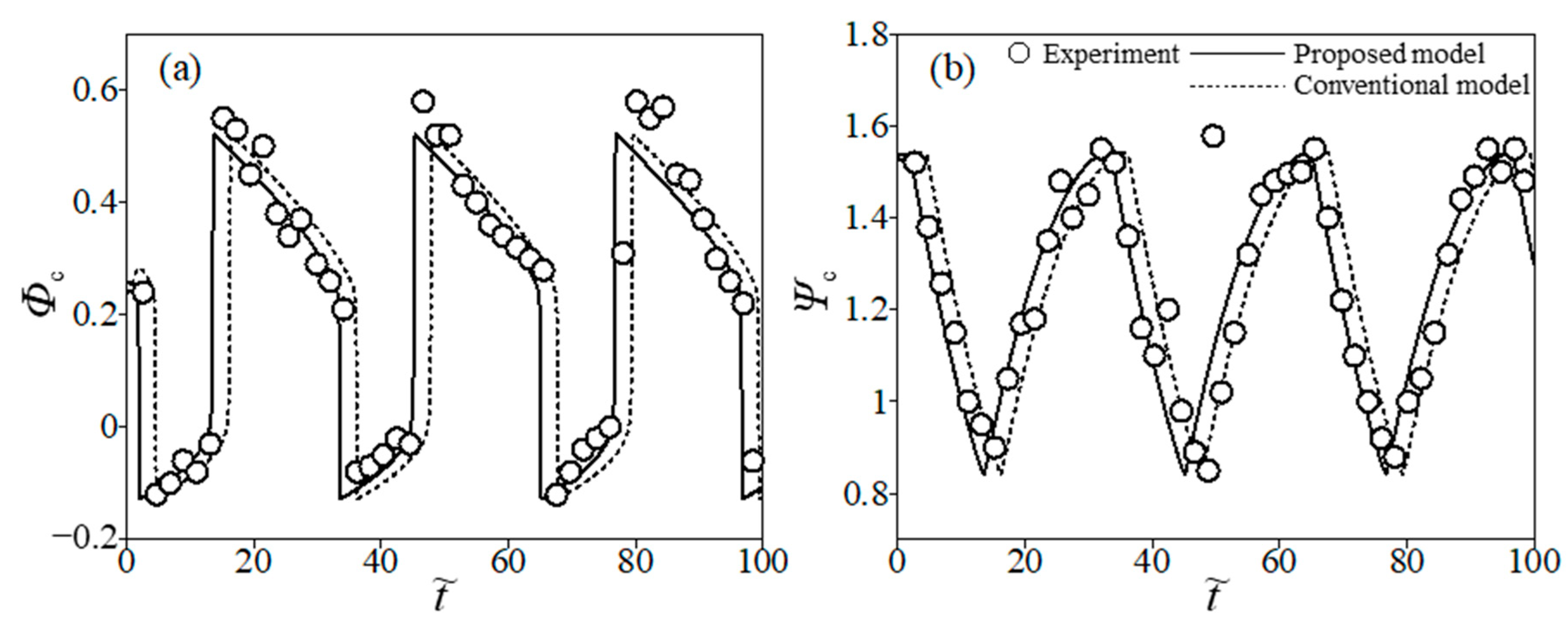
The Greitzer model developed for axial type compressor systems was used to predict deep surge oscillations in an industrial-scale centrifugal compressor. Figure 7 shows the steady-state performance of the compressor at 11,950 rpm, 15,950 rpm, and 21,100 rpm as measured by slowly closing the throttle valve. The surge at each speed was initiated and developed. The start of surge behavior is defined as the point at which the amplitude of the pressure begins to grow and a distinct oscillation frequency is found. The experiment for the deep surge was carried out only at 15,950 rpm because it was installed at an actual industrial plant. The system equations (Equation (1)–(4) were solved by a fourth-order Runge–Kutta method. In this numerical analysis, it is difficult to simulate the actual surge behavior with the parameters decided by the geometry of the compression system. Thus, the simulation was conducted by varying the compressor duct length and plenum volume. In addition, N = 0 , where N is the time lag in the revolutions, as per Equation (4). Figure 8a,b shows the behavior of the nondimensional mass-flow rate, ϕ c , and the pressure rise, ψ c , versus nondimensional time at B = 4.8716, respectively. The experimental data are plotted in these figures.

4.2. Proposed Model

4.2.1. Steady Flow Case

As derived previously, Equation (15) is a new momentum equation; thus, Equations (15) and (2)–(4) are the governing equations, which are solved by the fourth-order Runge–Kutta method. Figure 9 and Figure 10 show the surge predictions of the conventional model and the proposed model. When the surge parameter, B, is relatively small (Figure 9a,b), the proposed model predicts surge initiation in accordance with the experimental data. In Figure 10a,b, both models show similar behavior in a fully developed deep surge prediction with B = 4.8716. Surge development is affected by the friction term for a mild surge, however, the friction term did not influence the fully developed deep surge. Figure 10a shows the non-dimensional compressor performance with the simulation and measurement. The deep surge was simulated. The maximum negative mass flow occurs at the highest pressure. However, in the negative mass flow interval, the pressure decreases along the compressor performance line, increasing the mass flow. At the lowest pressure, the mass flow rate reaches the maximum flow rate at a high speed. Finally, as the pressure increases along the compressor performance curve, the mass flow rate decreases, and the cycle is repeated.

4.2.2. Unsteady Flow Case

Equation (28) is a modified momentum equation. In the Greitzer model, Equation (1) is replaced with Equation (28), and Equations (2)–(4) and (28) are solved by the fourth-order Runge–Kutta method. The simulations of the Greitzer model and the modified model are illustrated in Figure 11 with the experimental data. Figure 11a shows the mass flow vs. time, and Figure 11b shows the pressure rise vs. time. It is difficult to determine from Figure 11b whether there is good agreement between the experimental data and the Greitzer model; however, the mass flow in Figure 11a shows good similarity with the experimental data. The resulting simulation from the modified model shows better agreement than the simulation resulting from the Greitzer model.
From Figure 11, which compares the conventional model and the proposed model at the same time, the proposed model has the same amplitude and frequency as the conventional model, and the graph shifts in the leftward direction as a whole. From many experiment points, excluding outliers, it was confirmed that the simulation value of the proposed model had a small error. In particular, when checking the mass flow rate vs. time graph (Figure 8a and Figure 11a), it can be seen that a slight time delay occurs following the sharp rise of the graph in the conventional model, while this time delay has been resolved in the proposed model. In addition, in the pressure rise vs. time graph (Figure 8b and Figure 11b) it can be seen that the proposed model predicts the linearly decreasing stage better. Figure 10b shows the simulated surge cycle and experimental data along with the compressor characteristic curve at B = 4.8716.

5. Conclusions

In this study, a compression system surge was studied by means of experiments on an industrial-scale compressor and with the use of a lumped-parameter model. Cubic polynomials were used to describe the steady-state compressor performance curve, and each coefficient was found from the experiments. In the unstable region, the performance curve was estimated by means of methods from Moore and Greitzer [16], as it could not be verified experimentally. The experiments regarding the deep surge were conducted only at 11,950 rpm because the compression system was not built for the test but for the actual plant which supplied the fuel, i.e., natural gas, to two boilers in the ship.
It was found that the lumped-parameter Greitzer model showed satisfactory agreement with the measurements (Figure 8) of the deep surge oscillations in the industrial-scale single-stage centrifugal compression system at 11,950 rpm. Furthermore, the viscosity effects in the inlet pipeline were considered to determine its effects in a deep surge. First, the flow through the inlet pipeline was assumed to be steady. During the deep surge, the simulated surge cycle in Figure 9 was in an agreement with the Greitzer model. However, in a mild or classical surge the shapes of the surge cycles varied depending on the inlet velocity. Therefore, focusing on the deep surge mode, the simulation of the modified model was not improved in comparison with the conventional model.
Afterwards, the same flow was assumed to be unsteady. The surge cycles in both mass flow and pressure rise were moved to the left. As shown in Figure 11b, it is difficult to say that, in the pressure rise case, the simulation of the modified model better agrees with the experimental data compared with the conventional model. However, Figure 11a shows that the simulation of the modified model for the mass flow coincides with the experimental data 5% more accurately than any of the conventional models. Our measurement system was appropriate for the unsteady flow during surge, however, the orifice flowmeter for the transient reverse flow was not proper. Therefore, the reverse flow was determined by comparing the pressure difference of the orifice plate using a bi-directional differential pressure transmitter and the temperature difference at the compressor inlet and outlet [15,25].
Although many experiments could not be conducted because it was an actual plant, the experiments and numerical analysis described herein show that the modified model (Equation (28)) describes the surge cycle better than conventional models. As the demand for LNG carriers is increasing in the world and the capacity of centrifugal compressors for boil-off gas is increasing as well, various surge studies are required in order to extend the operational range of the compressors and provide a safe design.
In the current study, as actual plants were used as a target, the steady-state experiments had to be calculated with only B parameter variables limited to 11,950 rpm, 15,950 rpm, 21,100 rpm, and 15,950 rpm for the deep surge model. In addition, a new model supplementing the Greitzer model was proposed to consider of the viscosity effect at the inlet pipeline. In future research, we will expand these limited variables and proceed with a parametric study of other compressor model parameters that can affect parameters other than the B parameter. We intend to proceed with additional verification of the proposed model by targeting industrial-scale compressors that have not been tested beyond the lab scale.

Author Contributions

Conceptualization, J.L.; methodology, J.L.; software, J.L.; validation, J.L. and Y.C. (Yujin Cheon); formal analysis, J.L.; investigation, J.L.; resources, J.L.; data curation, J.L.; writing—original draft preparation, J.L.; writing—review and editing, J.L., Y.C. (Yujin Cheon) and Y.C. (Younseok Choi); visualization, J.L. and Y.C. (Yujin Cheon); supervision, Y.C. (Younseok Choi); project administration, Y.C. (Younseok Choi); funding acquisition, Y.C. (Younseok Choi). All authors have read and agreed to the published version of the manuscript.

Funding

This research received no external funding.

Institutional Review Board Statement

Not applicable.

Informed Consent Statement

Not applicable.

Data Availability Statement

Not applicable.

Conflicts of Interest

The authors declare no conflict of interest.

Nomenclature

aspeed of sound in ambient conditionsm/s
Aflow-through aream2
Awpipe wall aream2
Bdimensionless parameterN/A
Cxvelocity at inlet axism/s
dimpeller diameterm
Dpipe diameterm
fDarcy friction factorN/A
Ffrictionfriction forceN
ggravitational accelerationm/s2
Ggeometry parameterN/A
hLhead lossm
JnBessel function of the first kind (nth order)N/A
Leffective length of equivalent ductm
Ntime-lag in revolutionsRPM
m ˙ mass flow rateKg/s
Ppressurebar
Δ P pressure difference between plenum and ambientbar
Δ P c pressure rise in the compressorbar
Δ P T pressure rise in the throttlebar
Rcompressor rotor mean radiusmm
ttimes
Uimpeller tip speedrad/s
Vpplenum volumem3
YnBessel function of the second kind (nth order)N/A
τ ˜ relaxation timeN/A
ω H Helmholtz frequencym/s
ψ nondimensional pressure riseN/A
ϕ nondimensional mass flowN/A
t ˜ nondimensional timeN/A
ν kinematic viscositym2/s
ρ density at ambientkg/m3
u velocity along the x-axism/s
p Pressure along the x-axisBar
Subscripts
ccompressor
pplenum
tthrottle
sssteady state

References

  1. Boyce, M.P. Centrifugal Compressor: A Basic Guide; PennWell Books: Tulsa, OK, USA, 2020. [Google Scholar]
  2. Gravdahl, J.T. Modeling and Control of Surge and Rotating Stall in Compressors. Ph.D. Thesis, Department of Engineering Cybernetics, Norwegian University of Science and Technology, Trondheim, Norway, 1998. [Google Scholar]
  3. International Gas Union. 2019 World LNG Report; International Gas Union: Barcelona, Spain, 2019. [Google Scholar]
  4. Ludtke, K.H. Process Centrifugal Compressor-Basics, Function, Operation, Design, Application; Springer: Berlin/Heidelberg, Germany, 2004. [Google Scholar]
  5. Stenning, A. Rotating stall and surge. J. Fluids Eng. 1980, 102, 14–20. [Google Scholar] [CrossRef]
  6. Sundström, E.; Semlitsch, B.; Mihăescu, M. Generation Mechanisms of Rotating Stall and Surge in Centrifugal Compressors. Flow Turbul. Combust. 2018, 100, 705–719. [Google Scholar] [CrossRef] [PubMed] [Green Version]
  7. Xue, X.; Wang, T.; Zhang, T.; Yang, B. Mechanism of stall and surge in a centrifugal compressor with a variable vaned diffuser. Chin. J. Aeronaut. 2018, 31, 1222–1231. [Google Scholar] [CrossRef]
  8. Zheng, X.; Liu, A.; Sun, Z. Investigation of the instability mechanisms in a turbocharger centrifugal compressor with a vaneless diffuser by means of unsteady simulations. Proc. Inst. Mech. Eng. Part D J. Automob. Eng. 2017, 231, 1558–1567. [Google Scholar] [CrossRef]
  9. Sundström, E.; Semlitsch, C.; Mihăescu, M. Acoustic signature of flow instabilities in radial compressors. J. Sound Vib. 2018, 434, 221–236. [Google Scholar] [CrossRef]
  10. Reiber, C.; Chenaux, V.A. compressor mild surge simulation with variable nozzle models: Influence of throttle area on surge behavior and aeroelastic stability at reverse flow conditions. In Proceedings of the 13th European Conference on Turbomachinery Fluid Dynamics & Thermodynamics (ETC13), Lausanne, Switzerland, 8–12 April 2018. [Google Scholar]
  11. Emmons, H.C.; Pearson, C.E. Compressor Surge and Stall Propagation. Trans. ASME 1955, 77, 455–467. [Google Scholar]
  12. Greitzer, E.M. Surge and rotating stall in axial flow compressors. Part I: Theoretical compression system model. J. Eng. Power 1976, 98, 191–198. [Google Scholar] [CrossRef]
  13. Greitzer, E.M. Surge and rotating stall in axial flow compressors. Part II: Experimental results and comparison with theory. J. Eng. Power 1976, 98, 199–217. [Google Scholar] [CrossRef]
  14. Hansen, K.E.; Jørgensen, P.; Larsen, P.S. Experimental and Theoretical Study of Surge in a Small Centrifugal Compressor. J. Fluids Eng. 1981, 103, 391–395. [Google Scholar] [CrossRef]
  15. Fink, D.A.; Cumpsty, N.A. Surge dynamics in a free-spool centrifugal compressor system. J. Turbomach. 1992, 114, 321–332. [Google Scholar] [CrossRef]
  16. Moore, F.K.; Greitzer, E.M. A theory of post stall transient in axial compression systems. Part I: Development of equations. J. Eng. Gas Turbines Power 1986, 108, 68–76. [Google Scholar] [CrossRef]
  17. Moore, F.K.; Greitzer, E.M. A theory of post stall transient in axial compression systems. Part II: Application. J. Eng. Gas Turbines Power 1986, 108, 231–300. [Google Scholar] [CrossRef]
  18. Macdougal, I.; Elder, R.L. Simulation of centrifugal compressor transient performance for process plant applications. J. Eng. Power 1983, 105, 885–890. [Google Scholar] [CrossRef]
  19. Cortinovis, A.; Ferreau, H.J.; Lewandowski, D.; Mercangoz, M. Safe and Efficient Operation of Centrifugal Compressors Using Linearized MPC. In Proceedings of the 53rd IEEE Conference on Decision and Control, Los Angeles, CA, USA, 15–17 December 2014. [Google Scholar]
  20. Munari, E.; Morini, M.; Pinelli, M.; Spina, P.R.; Suman, A. Experimental Investigation of Stall and Surge in a Multistage Compressor. J. Eng. Gas Turbines Power 2017, 139, V009T24A018. [Google Scholar] [CrossRef]
  21. Grapow, F.; Liskiewicz, G. Study of the Greitzer Model for Centrifugal Compressors: Variable Lc Parameter and Two Types of Surge. Energies 2020, 13, 6072. [Google Scholar] [CrossRef]
  22. Meuleman, C.H.J. Measurement and Unsteady Flow Modeling of Centrifugal Compressor Surge. Ph.D. Thesis, Technische Universiteit Eindhoven, Eindhoven, The Netherlands, 2002. [Google Scholar]
  23. Samaan, A.A. Oscillating Flow in a Circular Pipe with Adverse Pressure Gradient. Int. J. Dyn. Fluids 2009, 5, 119–127. [Google Scholar]
  24. Uchida, S. The Pulsating Viscous Flow Superposed on the Steady Laminar Motion of Incompressible Fluid in a Circular Pipe. Z. Angew. Math. Phys. 1956, 7, 403–422. [Google Scholar] [CrossRef]
  25. Kim, H.R.; Song, S.J. Modeling of Surge Characteristics in Turbo Heat Pumps. J. Turbomach. 2011, 133, 041015-1–041015-9. [Google Scholar] [CrossRef]
Figure 1. Equivalent compression system.
Energies 15 04002 g001
Figure 2. System configuration: (a) 3D drawing and (b) schematic diagram.
Energies 15 04002 g002
Figure 3. Photographs of (a) the inlet guide vane and (b) the impeller.
Energies 15 04002 g003
Figure 4. Photographs of (a) the compressor suction and (b) the throttling valve.
Energies 15 04002 g004
Figure 5. Compressor performance: (a) dimensional and (b) non-dimensional.
Energies 15 04002 g005
Figure 6. Approximated compressor characteristic curve: (a) fitted with experimental data and (b) adjusted valley point.
Energies 15 04002 g006
Figure 7. Surge initiation at (a) 11,950 rpm, (b) 15,950 rpm, and (c) 21,100 rpm.
Energies 15 04002 g007
Figure 8. Transient non-dimensional (a) mass flow rate and (b) pressure rise with the experimental data and conventional model.
Energies 15 04002 g008
Figure 9. Comparison of the proposed model and the conventional model for surge parameter B = 0.41173.
Energies 15 04002 g009
Figure 10. Comparison of the proposed model and the conventional model for surge parameter B = 4.8716.
Energies 15 04002 g010
Figure 11. Comparison of simulation results: (a) non-dimensional mass flow rate and (b) non-dimensional pressure rise.
Energies 15 04002 g011
Table 1. Geometrical parameters of the compression system and compressor.
ElementParameterUnitValue
SystemCompressor duct length, Lcmm750
Throttle duct length, Ltmm800
Compressor duct area, Acm20.05
Throttle duct area, Atm20.01657
Plenum volume, Vpm30.358
ImpellerNumber of blades-16
Inducer dia. at hub, d1,hmm54
Inducer dia. at shroud, d1,smm155
Impeller diameter, dmm270
Vaned diffuserInlet diametermm311
Outlet diametermm439
Number of vanes-14
Table 2. Instrument list.
ItemTag No.RangeSignalMaker
Suction pressurePT10~2 barg4~20 mAFisher-Rosemount
Discharge pressurePT20~2 barg4~20 mAFisher-Rosemount
Suction temperatureTT1−200~+200 ℃4~20 mAJumo
Discharge temperatureTT2−200~+200 ℃4~20 mAJumo
Gas flowPDT1−70~70 mbar4~20 mASmart Rosemount
(bi-directional)
Publisher’s Note: MDPI stays neutral with regard to jurisdictional claims in published maps and institutional affiliations.

