1. Introduction
Electronic security systems (ESSs) are operated under varying environmental conditions [
1,
2]. They protect both humans and property. For this reason, they should offer reliable operation and be resistant to various adverse environmental impacts, especially in terms of improper electrical power supply. Because ESSs are used, among other things, to protect critical infrastructure facilities (including transport [
3,
4]), they should be characterized by a high availability index [
5,
6]. Various reliability-improving solutions [
7,
8] are applied in this respect, also involving the use of redundant structures [
9,
10]. However, this is not always economically justified. Another solution that improves the values of reliability and operating properties [
11,
12] of ESSs is the application of fuses within a power supply system. They constitute elements of anti-damage systems [
13,
14] that enable overcoming a dangerous situation [
15,
16,
17] and protecting ESS components [
18,
19]. One of the most important parameters that characterize fuses is the system break time
tw. The value of this parameter influences the security level provided by electronic security systems. Therefore, it is important for the safety fuses used in the ESSs installed in critical infrastructure facilities to exhibit proper parameters, in line with the requirements of the ESS manufacturer. However, the experience of the article authors in the field of ESS diagnosis and operation indicates that safety fuse parameters are not always correct, hence their use within an ESS may lead to a deteriorated security level. This was the purpose of the conducted destructive testing aimed at estimating the break times for a random number of glass tube, miniature 5 × 20 (mm) fuse links, with rapid operating characteristics, without a quenching medium, and a rated overcurrent intensity of 0.5 (A). An original dedicated measuring attachment, developed and constructed from scratch at the Faculty of Electronics of the Military University of Technology in Warsaw, was used for the research. The conducted tests enabled determining the time–current characteristics exhibited by the studied safety fuses. This allowed the authors to estimate the correct use of safety fuses in ESSs, assuming that the availability level would not decrease. The conducted actual fuse tests enabled rationally choosing them for ESSs.
First, the authors of the article analyze the current state of the field, followed by a discussion of the fundamental issues associated with fuses. Next, they characterize their original test bench for studying fuses and present and analyze the obtained results. The final section of the article is a discussion covering the obtained results, as well as the conclusions and an outline for further research in this field.
In the conducted tests, a proprietary measuring attachment was used, which enabled the measurement of fuse break times with the use of DC voltages and currents. Until now, similar tests were carried out only by manufacturers of the analyzed components for their own needs or by specialized centers certifying them for the purpose of verifying compliance with relevant standards or to obtain appropriate certificates, which are rarely made available to the public. The results of the presented tests constitute an independent verification of the protective properties of the analyzed components. They can be used by manufacturers and constructors of electronic devices (in particular, electronic security systems) to develop appropriate tools for assessing the effectiveness of protection of these elements in specific applications, which will largely affect their reliability and offered level of security. The unit cost of such a product can also be considered as one of the criteria. One of such tools may be the formulation of an appropriate factor. The authors of this article will try to develop it in the near future. This article is an introduction to a cross-sectional comparative analysis of the analyzed specific case of fuses from different manufacturers, reflecting almost the entire market offer available in the European Union.
2. Literature Review
Miniature fuses are protecting elements that are commonly used in a wide range of electronic and electrotechnical devices. These are technical solutions with their progenitors known to mankind since approximately the second half of the 1670s. The first patents for elements with a design closely resembling modern fuses were submitted just over a hundred years later. Despite such an abundant presence of fuses in the world of technology, they did not become the subject of comprehensive studies before the 20th and 21st centuries. The publication [
20], which is entirely devoted to the aforementioned components, is particularly noteworthy. The overview publications [
21,
22] may significantly supplement the state of knowledge, whereas the authors of [
23,
24] focused on the purely practical issue of selecting characterized components at the stage of designing modern electronic and electrotechnical devices, taking into account normative requirements. Of particular note is a publication that presents a practical method for the selection of appropriate fuse-links and calculating the melting point of a fuse-link fiber in the context of electronic equipment reliability [
25]. It also comes up with a proposal for an appropriate measuring stand based on a pulsed DC voltage converter. One of the most popular issues of interest to the scientific world with regard to fuse-links is an attempt at understanding the phenomena arising upon the fuse-link fiber melting (both during pre-arcing [
26] and arcing [
27], and this also applies to high-breaking capacity fuses [
28]) and obtaining tools that would enable their reliable modelling. Contemporary researchers have tried to achieve this through experiments [
29,
30] and numerical calculations, taking into account heat transfer to the fuse composite base [
31] and classical mathematics [
32]. A similar approach can also be observed in relation to fuses characterized by a high breaking capacity [
33]. Yet another aspect of the analyzed solutions focuses on one of the most important parameters in practical terms: time–current characteristics. In most cases, they are measured using a point-by-point method. This solution comes with certain disadvantages, which involve the need to conduct many measurement series, entailing the destruction of a vast number of fuse-links. Therefore, aggregated solutions are proposed. They enable reaching satisfactory results while reducing the need to execute practical tests [
34]. Safety fuses are sometimes the subject of interesting, unprecedented experiments. Such examples include an attempt to determine the nature of conducted disturbances (a term related to the issues of electromagnetic compatibility), which are generated by an electric arc that appears during the arcing time, in the course of a fuse trip process [
35]. The methodology of automatic visual inspection of miniature fuse-links based on automatic learning techniques is particularly noteworthy [
36]. Safety fuses, like any other aspect of technical fields, undergo continuous development. The aim is to miniaturize the analyzed elements while increasing their break properties [
37]. The authors note that the work that discusses the impact of fuse operations under typical operating conditions and the associated aging processes on the change in time–current characteristics of such elements [
38].
Despite so many studies in the field of determining the technical condition of safety fuses, there are no papers directly related to their impact on ESS operation. Therefore, the authors have addressed this issue and discuss it in this article.
3. Cartridge Fuse Characteristics
From the perspective of the reliability theory, fuse-links acts as an anti-failure subsystem (also known as anti-damage) [
39]. This means that such a system should be treated rather as a last-resort solution aimed, in the best-case scenario, at avoiding a damaged device in situations where the operation of other subsystems (e.g., shielding or intervention [
40,
41,
42]) failed to produce a desired outcome. Unfortunately, in practice, the tripping of an anti-failure system most often entails only a partial mitigation of the damage scope, which, as such, are unavoidable in a great majority of cases. Therefore, it should be emphasized that the issue of applying such protections is a certain dilemma between a very probable damage to a part or even the entire device if it trips or a catastrophic damage (the outcomes of which might paradoxically become a real threat to the property and people in the surroundings of such a device, in the form of a fire or electric shock risk) in the event of completely discarding the use of such protection measures.
In terms of electronics, safety fuses (miniature) protect a given circuit fragment against overcurrent outcomes (resulting from, among other things, commutation phenomena or excessive, unforeseen elements in the design load of a given electrical circuit), but also against short-circuits, which are always an effect of a failure, from a practical point of view. This is a consequence of broken electrical circuit continuity in one or many modules of a given device. An extreme example of protective tripping by the aforementioned element is the total isolation of the electricity supplied from such a device. The arguments confirming the common use of the analyzed elements include simple communication, the very low unit price of a fuse-link (a replaceable element), and a relatively smooth replacement process which does not require comprehensive training, provided that basic security measures are applied when handling electric and electronic devices as part of maintenance activities. Under normal operation (with current intensities lower or equal to the load current), a fuse behaves as a peculiar type of a “replaceable” fragment of a conductor (e.g., a conduit, track on a PCB (
printed circuit board), etc.). On the other hand, in the event of damaging phenomena (e.g., a short-circuit), the intensity of the current flowing through the fuse is a much higher overcurrent range. As a result, the flow of such a current leads to the gradual melting of the fuse (fuse element) fiber, resulting in the current switching off and breaking further uncontrolled current flow within a given circuit. This happens because the phenomenon of an electric current flowing through a conductor entails the generation of certain energy losses released within its structure as heat—the so-called Joule heat, the value of which in DC circuits can be expressed as follows:
where:
A more accurate consideration of the material properties and geometrical dimensions of a conductor enables expressing its resistance as:
where:
A fuse-link fiber acts as a conductor in a miniature fuse. The manufacturers of the specified protective elements try to select their parameters so that the Joule heat released therein during a current flow is small enough not to damage it (causing melting or evaporation in extreme cases) upon being subjected to current intensities lower or equal to the load current, which is the primary design parameter of such solutions. Resistivity is a quantity closely related to the material used to manufacture the fuse-link fiber. In practice, the most common ones are copper, nickel, and steel, and less frequently, gold and silver, or more precisely, the alloys of the selected aforementioned metals, in proportions that constitute the secrets of individual manufacturers. For economic reasons, more and more conductors are used with their cross-section entirely made of a noble metal instead of gold- or silver-plating a finished fiber. Because fuse-links are standardized subassemblies, they have certain unified dimensions. The authors of this study focused solely on 20 (mm) long fuses, which naturally determines the minimum fuse-link fiber length in such an element. If required to achieve desired parameters, fuse manufacturers form the conductor into a spring, appropriately extending its total length. However, this operation mainly utilizes the benefits of mechanical and dynamic properties of such a formed fiber. The last of the aspects are the conductor diameters, the value of which, in commonly encountered fuses, ranges from 0.01 to 0.5 (mm).
By compiling Formulas (1) and (2) and assuming an ideally round and homogeneous cross-section of the fuse-link fiber along its entire length, we get an expression that fully describes the released Joule heat using variables that are most important in terms of electronics:
Their double responsibility should be noted in the context of using fuses in electronic security systems (ESSs). First of all, they are protective elements, and this scope has been previously characterized more thoroughly. The second aspect of this function is associated with the fact that the analyzed elements are installed in such unique solutions as ESSs, particularly protecting their modules and components, as well as their peripherals. Placing the said element in a commercial electronic device requires a consideration of a completely different level of fuse responsibility and the potential consequences of resulting damage, which is usually limited to a frustrated operator or a wider group of decision makers, and to a certain set of losses that, after a more in-depth analysis, can be expressed in a monetary equivalent. In the case of an entire ESS or its parts, the extent of potential damage outcomes takes the issue in question to a completely different level. By assumption, electronic security systems are used to protect broadly understood goods. Their first group includes all tangible items as, for example, property, works of art, valuable and unique items, antiques, money, gold, securities, etc., the value of which is sometimes hard to clearly determine. Another set of valuable goods are intangible assets, which are impossible to be obtained physically (e.g., the company data on a new product prototype, stored in a dispersed form within the network infrastructure of a company, where the physical acquisition is impossible; however, it can be copied after an intruder penetrates company premises). A particular group of intangible assets with a hard-to-determine value, the security of which is often entrusted to electronic security systems, includes the health and life of people within an area subject to monitoring by an individual ESS. In the operational perspective related to ESSs, each incorrect or excessively delayed response of an anti-damage subsystem (the representatives of which include, e.g., safety fuses) will directly translate to the security level offered by a given security system. Depending on the efficiency of a safety fuse trip, the consequences will vary between one or more security state risks, and in an extreme case, even total ESS unfitness, resulting in a state of a complete lack of security (a break in the electricity supply to at least one ESS device or module). This will mean that the previously mentioned values are partially or fully deprived of protection measures. The presented reasoning leads to an important statement. Elements protecting the correct operation of electronic security systems are of critical significance to their functioning, hence special attention should be paid to the process of verifying their theoretical parameters (declared by the manufacturer) and their actual operation. A similar philosophy can be expanded onto other elements, modules, and devices making up electronic security systems. For these reasons, attempts are made at experimentally verifying the level of confidence in the functions they implement, which are directly associated with ensuring safety. A good example in this case is the verification of tripping thresholds for the detection circuits of intrusion detection systems under varying climatic conditions [
43].
In the case of safety fuses, a critical parameter in terms of the operational reliability of electronic security systems is the circuit breaking time tw. In order to better understand its importance, the authors note that a fuse-link trip under overload conditions may be divided into two stages. The first one lasts from the moment overcurrent appears in a circuit protected by a given fuse, which leads to Joule heat being released in the fuse-link fiber, leading to breaking its continuity. It is called the pre-arcing time tp. The authors note that fuse element disintegration is not tantamount to the cessation of the current flow phenomenon. In reality, it is maintained by the electric arc formed above the said gap. The flow time of the current of such an origin, until its complete decay, is called the arcing time tł. Measuring the aforementioned parameter of safety fuses by various manufacturers, based on the same measuring instruments and methodology, will enable a comparison and evaluation of the practical protective properties of the characterized subassemblies. This enables an easy observation that the aforementioned parameter fully describes the fuse’s circuit breaking potential in a specific application, taking into account all phenomena that might impact its value.
Scientists analyzing the protective elements acting as an anti-failure subsystem sometimes speak of subassemblies that protect a given system through self-damage—this is also the nature of safety fuses. Such a case leads to an issue with implementing experiments aimed at obtaining information on the protective properties of the analyzed fuse-links that have to undergo a series of destructive tests. Despite the fact that destructive tests are a unique form of experiments themselves, even in this perspective, fuses constitute an interesting and particular study subject matter. Fuse-links, which unlike, e.g., a construction floor beam, the properties of which are also verified through destructive testing, are not themselves a protective element. In such a situation, these are structural elements, the presence of which is required to construct a building. Safety fuses are an optional element in electric and electronic devices, and their intervention aimed at protecting the device they are installed in equals its destruction. The authors note the noteworthy fact that, regardless of the nature of elements subject to such experiments, the common denominator is that destructive tests are conducted wherever security is an absolutely top priority (e.g., car or aircraft crash tests, test fires, etc.). Such experiments are also associated with the need to satisfy a rather demanding engineering issue. It is necessary to develop an appropriate test bench which will not only enable measuring the parameter of interest, but also ensure it is recorded during every single test, without exception. This rather unusual requirement is associated with the fact that we only have one single chance to test a selected (e.g., through a random draw) unit. Yet another aspect related to a test bench is for it to provide such technical solutions that will enable testing its correct operation and configuring the recording and measuring instrumentation in such a way that the risk of the fuse-link being destroyed in vain is minimized during the actual destructive test. The last difficulty is the need to infer the reliability of a certain group (or more precisely, a population) of such elements (e.g., all fuse-links by a given manufacturer with a specific rated current value, within a specific production batch) based on the test results of a certain representative group, and transferring the considerations regarding an entire population into the statistical domain since the tested fuse is subject to irreversible damage due to the conducted experiment. The desire to obtain indisputable results would require conducting destructive tests on all units within a given batch, which is obviously pointless since this would provide knowledge on components that are impossible to be used.
4. Materials and Methods
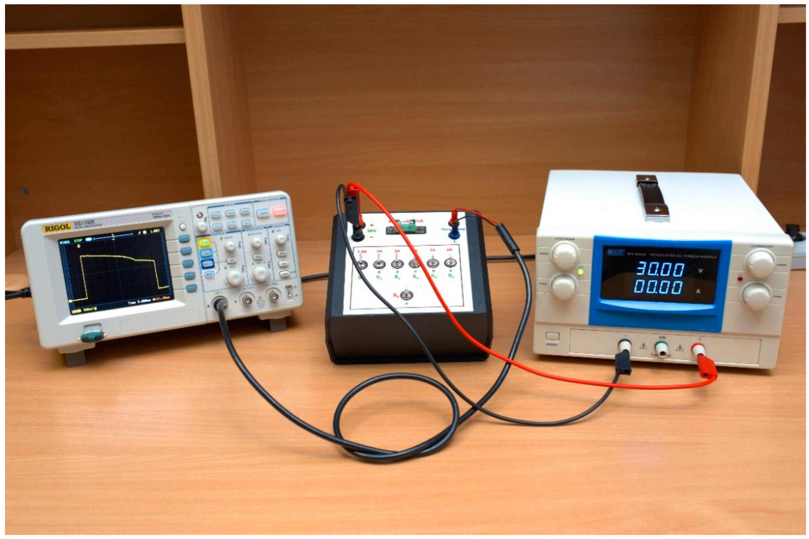
In order to verify the reliability of the characterized subassemblies, the authors developed a universal test bench for the destructive testing of miniature fuses by various manufacturers. It consisted of a RIGOL (Suzhou, China) DS1102E (a double-channel digital oscilloscope); an M10-QS3020 stabilized, continuous laboratory direct voltage laboratory power supply by MCP (Shanghai MCP Corp., Shanghai, China); and a DC [
44,
45] test attachment developed at the Institute of Electronic Systems at the Faculty of Electronics of the Military University of Technology (ISE/WEL WAT). MLN 100/1 cables by Hirschmann (a brand belonging to SKS Kontakttechnik GmbH, Niederdorf, Germany) were used to execute a power rail connecting the laboratory power supply and the measuring attachment. The said test assembly is shown in
Figure 1. The laboratory power supply acted as a power supply system that generated a 30 (V) forcing voltage, with a maximum current of 20 (A). The device in question had been added to a fixed attachment containing a system, which consisted of, among other things, five bipolar transistors and one rectifying diode, the intention of which can be largely reduced to a power source. The output of the characterized circuit was connected using a tested fuse (containing a fuse-link trip signaling system with an LED light-emitting diode connected in parallel) with a system of toggle switches marked S1 to S6, the task of which was to simultaneously connect successive high-power ceramic resistors to the circuit. Their values were chosen so that a test current with a selected, discrete intensity value would flow through each of them. The outcome was one resistor forcing the flow of a current with an intensity of 1.5 (A) and five resistors, each forcing the flow of a 2 (A) current. For example, conducting a destructive test of a safety fuse using a 9.5 (A) current required activating the S1 forcing switch with a 1.5 (A) current and four forcing switches, each with a 2 (A) current, e.g., from S2 to S5. In order to prevent an uncontrolled destructive test initiation, the power supply voltage was supplied to the current source system through changing the position of the S0 toggle switch. The voltage waveform within the tested fuse-link was observed via a digital oscilloscope with a single mode triggered time base generator supplied by a dedicated voltage resistance divider system (9.1 (kΩ) and 1,1 (kΩ)), connected in parallel to the fixed base of the fuse-links. The signal was recorded using the oscilloscope connected to a 1.1 (kΩ) tap. The authors would like to emphasize that the decision to use a DC system within the destructive testing was conscious. In devices and modules of electronic security systems, nearly the only AC fuses can be found in power supply transformer circuits to protect the said element against overload, or if the device had a metal casing, to protect users against the appearance of potential on the metal elements forming the body. The vast majority of fuse-links are used in circuits downstream of the rectifying system, where only voltages and direct currents are present as supply signals. Examples of such devices include relay modules, intrusion detection system motherboards (and more precisely, fragments of the power supply circuit responsible for charging backup supply sources in the form of batteries), etc.
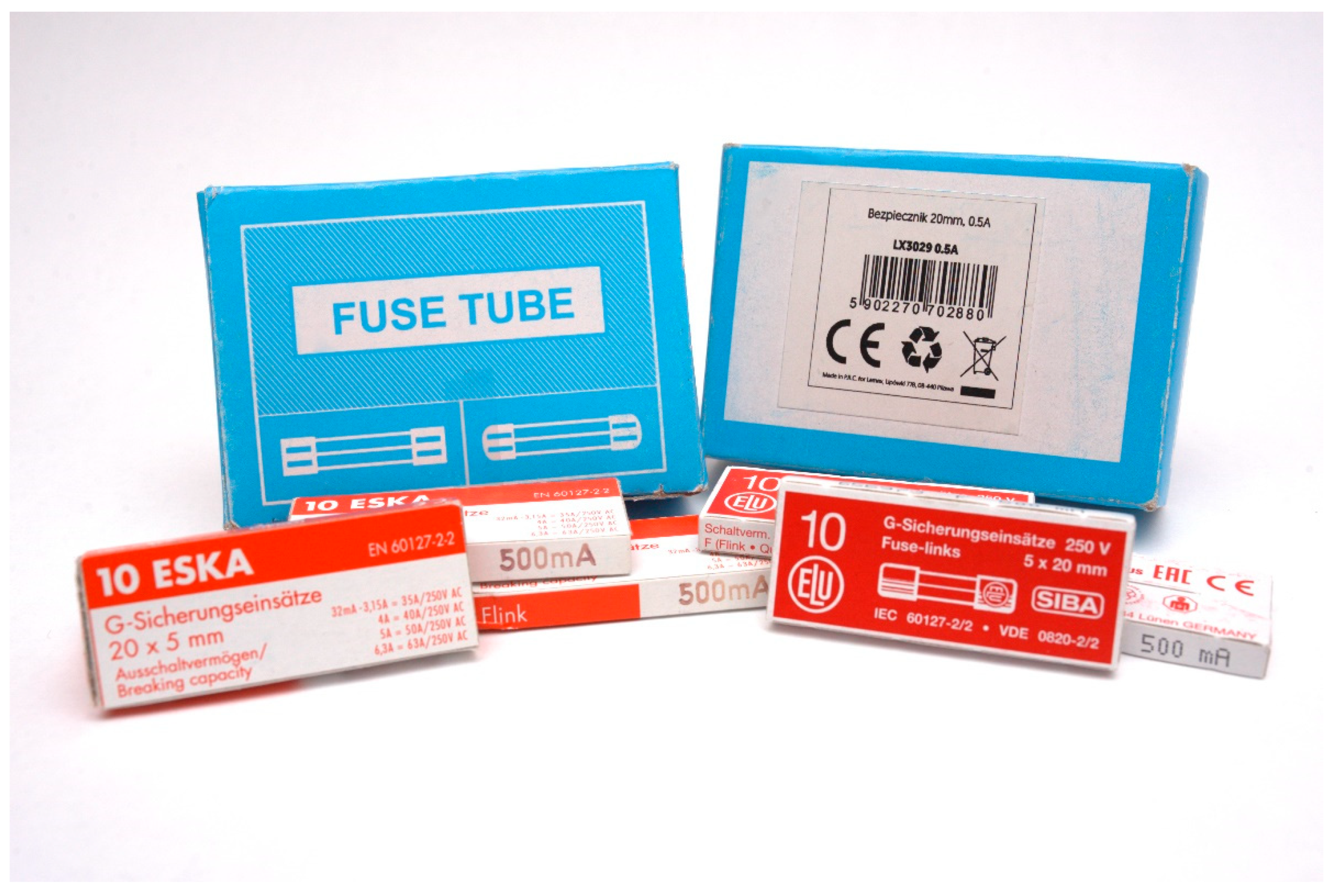
The authors decided for the study subject matter to be 5 × 20 (mm) glass tube, fast-acting miniature safety fuses without a quenching medium (
flink) with a rated current of 0.5 (A), as produced by selected manufacturers. Protections with such a performance specification are most commonly used in a wide range of electronic devices equipped with semi-conductor elements (such as the bipolar transistors, diodes, field-effect transistors, microcontrollers, and semi-conductors required to implement bit operations) that are particularly exposed to short-circuit and overload phenomena. In turn, fuse-links with the said dimensions are, somewhat, a standard throughout the entire European Union. The tests involved products by ESKA Erich Schweizer GmbH (Kassel, Germany), model: 520.614 (of the product family 520.600) and SIBA GmbH (Lünen, Germany) model: 179020. In addition, the authors purchased unknown-brand fuses distributed in Poland by Lamex from Pilawa, with a model designation of LX3029 0.5A, manufactured within the People’s Republic of China (PRC). An attempt at contacting one of the distributors to obtain a product data sheet was made in the case of the latter of the fuse-links above. Unfortunately, the authors did not obtain the said document until the day of publishing this paper. The appearance of the subassemblies used in the tests is shown in
Figure 2. The authors would like to stress that the selection of the individual fuse-link manufacturers was dictated by the will to verify circuit breaking capacities of products of varying quality under identical, repeatable conditions. The decision for the experiments to involve fuses with a rated current equal to 0.5 (A) was made due to the possibility of recording overcurrent measuring points constituting a greater multiple of the rated current.
Moreover, efforts were made to ensure that all products selected for the tests represented different price ranges so that the test covered both cheap and rather expensive items. A cost summary related to the fuse-links used in the tests can be found in
Table 1. This allows the analysis of the obtained results to become multi-faceted and it will be possible to determine whether, in the case of fuses, a product unit price goes hand-in-hand with the effectiveness of protecting electronic devices, or maybe there is no correlation between these features and the price difference is only a margin for the manufacturers and distributors, resulting from the desire to profit from the repute of a given brand.
The measurement methodology used can be divided into two stages. The first one involved configuring and testing the test bench to ascertain that all measuring instrumentation settings enabled the correct recording of the interesting parameters, without the need to incur unnecessary losses involving burnout of successive fuse-links, and thus not leading to any measurement results. The laboratory power supply voltage range had to be set at 30 (V), whereas the potentiometers adjusting current efficiency had to be set at their maximum positions. The oscilloscope required activating only one channel. The channel gain enabling the optimal visualization of the voltage waveforms within the tested fuse-links was equal to 500 (mV/div), with the position of the first channel set at a level of −1.5 (V). The time base value settings were selected experimentally after conducting the first measurement series so that the expected circuit breaking time of the tested fuse-link fell within the selected time frame. After selecting a correct time base generator value, the horizontal parameter was set in very close to the edge of the oscilloscope screen’s left edge. The trigger section was also configured so that the signal was recorded by the measuring device once, with a rising edge with a 1 (V) signal from the first channel (the DC measuring attachment was connected to it). The correctness of the entire set-up was verified several times by installing a fuse-link in the fixed holder of the test bench and by changing the position of only the S0 toggle switch, supplying it with an approximate 0.2 (A) current, without connecting loading resistors, and resetting the oscilloscope time base generator trigger each time.
The next stage of the experiments involved the actual tests. It consisted of randomly selecting eleven fuse-links by a given manufacturer from the entire packaging and verifying circuit continuity in each of them in order to eliminate manufacturing defects. Next, the destructive tests consisted of destroying one fuse in each random sample selected this way, with an overcurrent intensity value offered by the measuring attachment. Each case of testing fuses by different manufacturers involved applying the same toggle switch combination in order to obtain the same overcurrent value. Each of the voltage waveforms within a tested fuse-link unit was recorded using an oscilloscope and exported to an appropriate file. Ultimately, using the cursors of the said measuring instrument, the authors measured the breaking time tw of the specific safety fuse units being experimented on.
5. Results and Analysis
Measurement results were recorded in each case and are summarized in
Table 2 and graphically interpreted in
Figure 3 in the form of time–current characteristics. Two measurement series were completed in the case of the fuse-links distributed by Lamex. The course of destructive tests and the individual stages of the fuse-link fiber disintegration process and all accompanying phenomena were recorded in time-lapse and presented in [
Videos S1–S3] for the products of all selected manufacturers on the example of an overcurrent with an intensity of 3.5 (A).
The authors note that the shape of the resulting characteristics is in line with the theory. The strongly decreasing fuse breaking time as a function of the overcurrent intensity can be easily noticed. The Joule heat value, which is the main factor leading to fuse-link fiber disintegration is worth mentioning here. It increases with the square of the current flowing through it.
The first conclusion when analyzing the obtained measurement results is that the breaking time of the fuse-links manufactured under an unknown Chinese brand is significantly longer than the results achieved by the branded products. To be more specific, the worst-case scenario (at an overcurrent equal to 3.5 (A)) circuit breaking time of the fastest fuses (SIBA GmbH) is 5.41 times shorter. In turn, this value increases to 7.80 at an overcurrent of 9.5 (A). By analogy, when comparing the tested products by ESKA Erich Schweizer GmbH and SIBA GmbH, we obtained the least and most favorable proportionality coefficients, equal to 1.30 and 2.12, respectively. However, in this case, these values were obtained for overcurrents of 3.5 (A) and 10 (A) (as well as 11.5 (A)).
Let us try to analyze the obtained results in terms of the tested fuse-link purchase cost. The total cost of purchasing one hundred of the said protective elements by different manufacturers was adopted as the starting criterion. It is a usual order of magnitude applied by companies dealing with the operation of electronic security systems that have been functioning in actual facilities for some time now. It should be noted that it is common in the electronic industry to condition the end price of a product on the number of ordered units, and for the minimum number of products to be ordered for the order to be processed at all. The most common quantitative ranges are: 0–9, 10–49, 50–99, 100–499, and 500–1999 pieces. When analyzing the data in
Table 2, it can be observed that fuses of the unknown manufacturer, distributed by Lamex (Pilawa, Poland), are almost three times cheaper than the products by SIBA GmbH and approximately 3.7 times cheaper than those by ESKA Erich Schweizer GmbH. In this case, it is evident that the determinant of product quality, understood as fuse-link circuit breaking speed, is the price. However, please note that the fastest fuse-links are cheaper than the ones with the next best result by approximately PLN 7.85 (approximately
$2.00 as of 11 February 2022) when buying one hundred units, and it is somewhat a surprise.
Because the tests were conducted based on an identical measurement methodology and used the same measuring instruments, the factors above should not be the reason why the results associated with the tested fuse-links manufactured in the People’s Republic of China such significantly deviated from other products of more renowned manufacturers. Therefore, the attempt at determining, and hence verifying, whether the conducted measurements are reliable should be deemed a significant issue. Achieving this objective would require conducting a statistical analysis of the measurement results and using them as a base to determine their uncertainty [
46], assuming that their nature is accidental. Two measurement series of the fuse-links distributed by Lamex were used for the analysis for this purpose. It was assumed that, in this case, measuring the breaking time for each overcurrent could be treated as a separate test repeated twice (
N = 2). From now on, in order to present calculation examples, we will consider the breaking time
tw obtained for an overcurrent of 1.5 (A) only. The first step involved calculating the best approximation
twnp of the
tw parameter based on two experimental measurement results for this value, expressed in the form of an arithmetic mean of the obtained measurements:
where:
N is the number of breaking time tw measurements for the fuse-links of a given manufacturer, with the same overcurrent intensity value within a given measuring session; and
twi is the number of the i-th breaking time tw measurements for a specific fuse-link unit of a given manufacturer, with the same overcurrent intensity value within a given measuring session.
The absolute measurement uncertainty of each of the
i measurements treated separately is determined by standard deviation
σtw. Due to the fact that the experiment series consists of only two measurements, the said value will be calculated using the formula variant below, called the sample standard deviation:
where:
N is the number of breaking time tw measurements for the fuse-links of a given manufacturer, with the same overcurrent intensity value within a given measuring session;
twi is the number of the i-th breaking time tw measurements for a specific fuse-link unit of a given manufacturer, with the same overcurrent intensity value within a given measuring session; and
is the best approximation of the measured value twnp of the tw parameter in the form of an arithmetic mean N of its experimental measurement results.
As a result, the measured
twzw of the first two breaking times can be expressed as:
However, as previously mentioned, the best approximation of the measured break time value
twnp is the measurement mean. In such a case, we are interested in the uncertainty of this result, which is represented by a standard deviation of the mean. In this particular situation, let us use the formula below, which is based on the definition of a sample standard deviation:
where:
σtw is the absolute measurement uncertainty of each i-th of the N completed measurements treated separately, expressed by a measure of standard deviation; and
N is the number of breaking time tw measurements for the fuse-links of a given manufacturer, with the same overcurrent intensity value within a given measuring session.
Let us express the obtained absolute uncertainty as a percentage of relative uncertainty based on the following equation:
where:
Ultimately, it can be concluded that the best approximation of the measured breaking time tw exhibited by the fuse-links distributed by Lamex, for an overcurrent of 1.5 (A), is 562.00 (ms), with an uncertainty of 34.00 (ms), which amounts to 6% of the results. If a similar analysis was conducted for all overcurrent intensity values of the tested fuses from an unknown manufacturer, the result would be a relative percentage error ranging from 1.8 to 7.7%.
Practical measurement uncertainties of this order evidence their rather high accuracy, and, importantly, their repeatability. As a result, we can exclude the used measuring equipment and adopted methodology as the main factors that determine the discrepancies between the breaking time of the fuse-links manufactured in PRC and the products by SIBA GmbH and ESKA Erich Schweizer GmbH.
Moreover, Equation (7) clearly indicates that the level of measurement uncertainties can be reduced up to a certain point by increasing the number of measuring sessions for the given fuse-links, which can be easily proved by comparing Formulas (6) and (7) and the resulting uncertainty values.
All of the so far collected arguments evidence that the main reason for the obtained measurement uncertainties is the manufacturing spread of these fuses. In such a case, the source of such poor results by the fuses distributed by Lamex must originate from the fuse-link itself, most probably its fiber. The reason behind this fact might be the incorrect metal alloy used for its manufacturing, the wrong wire diameter or process limitations of the manufacturer, which could provide constancy and repeatability of the said parameter throughout the entire conductor, or an incorrectly selected ultimate fiber length.
The branded fuses are characterized by a much faster breaking time than the non-branded fuses. This proves that despite the same declared technical parameters (e.g., rated current), they constitute a better anti-failure system. What is more, based on the conducted measurements, it can be concluded that the fuses by ESKA Erich Schweizer GmbH and SIBA GmbH exhibit a similar safety level since the differences in the achieved breaking times can be deemed negligible. The said fact is much better depicted by a direct summary of the oscillograms shown in
Figure 4, which represent the aforementioned parameter for an example overcurrent intensity of 1.5 (A), placed one below the other, while maintaining the same channel gain and time base generator parameters (in other words, identically scaled) for all tested fuses.
In an approach at reviewing the just-analyzed issue from a different perspective, it can be noted that manufacturers and designers of ESS equipment and modules, as well as the people responsible for the maintenance of electronic security systems, share a common goal implemented through achieving the highest possible reliability and safety levels, which might not be achieved despite sincere intentions in this regard. Electronic device designers are often unaware of certain actual phenomena occurring in electrical circuits or affecting individual components. Therefore, the designer makes an a priori assumption at the device engineering stage regarding its hypothetical operation—a fuse-link, in this case. On a schematic diagram, it is a kind of “ideal” element, behaving the same way every time. Similarly, a fitter or maintenance technician installing a safety fuse is mainly interested in its characteristics (quick-acting, time-lag, etc.) and rated current value. This may lead to a certain hypothetical and potentially dangerous situation. Let us assume that a company is administering a number of facilities with installed electronic security systems. All systems within such facilities have a certain module of the same type, which is protected by a fuse with identical parameters to the ones tested as part of this study, except that each facility was fitted with fuse-links by a different manufacturer. The presented example leads to some surprising conclusions. In the event of an identical damage factor appearing in each of the said facilities that will trigger a fuse, we will get completely different fuse-link breaking times, which may translate to fully contrasting damage extents directly affecting the safety levels, despite the application of elements that, in theory, share identical technical parameters. What is most surprising is the fact that designers do not have to be necessarily aware of such mechanisms, and fitters do not notify manufacturers of this fact, even when they notice certain correlations. The consequence is a vicious circle which prevents manufacturers from developing certain guidelines in the form of, e.g., service bulletins limiting the selection of fuse-links, e.g., for selected manufacturers, or communicating that the selected modules they manufacture are much more sensitive to the fuse-link breaking time than others.
Assuming that the presented attachment does not ensure forced overcurrent intensities to be exactly equal to the values declared at the design stage, each case of test implementations using the same measuring instruments and the same fully repeatable methodology guarantees a good result accuracy and certainty that the observed tendencies and discrepancies between the fuse-links by the individual manufacturers are actual phenomena, with the cause not attributable to the aforementioned elements of the conducted tests.
6. Discussion and Conclusions
Summing up the previous studies, it should be concluded that safety fuses have a strategic role in protecting electronic devices against the most serious outcomes of damage phenomena, originating from the flow of overload currents. The burden becomes much more apparent when the said elements are characterized in terms of their application in electronic devices, which at the same time are components of electronic security systems. The aforementioned phenomena result from the fact that the analyzed subassemblies are components of devices whose only purpose is to protect property, human health, and, in extreme cases, life. All phenomena resulting in the partial or complete unfitness of electronic components of ESSs directly translate, to a lesser or greater extent, to the safety level, the constant level of which such systems are designed to maintain.
An original research attachment, developed at the Military University of Technology in Warsaw, was used to conduct a number of destructive tests involving miniature fast-acting fuse-links, without a quenching medium and with a rated current of 500 (mA), produced by the selected manufacturers. The study used the products of various companies from various price ranges, while maintaining a fully repeatable measurement methodology. Therefore, it can be concluded that the obtained measurement results are characterized by good repeatability and objectivity.
The first observation, directly associated with analyzing the obtained test results, is the fact that in the case of fitting electronic devices with fuse-links by different manufacturers, designed for operation at a theoretically same rated current (500 (mA) for the analyzed components), significantly varying breaking time tw values are obtained, in practice. The worst results (hence, the longest breaking times) were exhibited by the safety fuses of an unknown manufacturer, produced in the People’s Republic of China. On the other hand, the products by SIBA GmbH can boast of the best breaking time among the subassemblies used in the study. The relation of breaking times of the best and worst selection within the entire overcurrent test range varies from 5.41 to 7.80. It should be noted that this is a significant disproportion which is not so evident when comparing the results for the branded products (ESKA Erich Schweizer GmbH and SIBA GmbH). The following conclusions can be drawn in this respect: the use of branded fuse-links ensures achieving considerably shorter breaking times in the event of damage factors in electronic devices compared to far-east products, the origin of which is difficult or, in extreme cases, impossible to determine.
Another important conclusion coming to mind after analyzing the obtained results is a recommendation for the manufacturers of electronic security system components and elements to have their research and development facilities make an urgent attempt at estimating the potential outcomes of a prolonged circuit breaking process by a fuse-link in their products. It is also recommended for the user manuals of their products to include a relevant information clause or a suggestion in terms of the preferred safety fuses used in their products (such as how, e.g., car manufacturers do in relation to their recommended engine oil manufacturers).
An attempt was also made at statistically estimating the measurement uncertainties of the obtained test results based on two measurement series involving the fuses of unknown origin, which were distributed in Poland by Lamex. Based on the above, a conclusion can be made that the measurement results are consistent with the theoretical knowledge. Moreover, the estimated uncertainty level enables a conclusion that the differences in the obtained circuit breaking times of the fuses from the selected manufacturers are authentic and result almost solely from the physical properties of the fuse-link fibers used therein. On the other hand, the developed measuring attachment and the adopted measurement methodology were selected correctly and ensure the test implementation with adequate credibility.
Based on the above, yet another conclusion can be formulated: even assuming that the overcurrents forced by the measuring attachment, developed at the Military University of Warsaw, significantly deviated from the declared values (adopting a purely hypothetical assumption that actual overcurrent was equal to 3.0 (A) for a toggle switch set-up suggesting a current of 3.5 (A)), this fact still does not invalidate the credibility of the obtained results in terms of the time–current characteristic curve shapes and obtained significant differences in the fuse-link circuit breaking times for the individual manufacturers, especially the ones represented by proportionality coefficients, which are relative measures.
The conducted economic analysis does not provide such unequivocal results as the experiments. However, it can be used to infer rather generic conclusions only. These include stating a fact that the cheapest fuse-links available on the market (the unit cost of which significantly differs from typical market levels) will most probably offer considerably worse values of the critical parameter in terms of rationale behind the existence of fuses: the breaking time
tw. After the results for the products from individual fuse-link manufacturers were compared to the economic data from
Table 1 and it turned out that the best safety fuses were not the most expensive ones, it should be concluded that the economic criterion has to be treated as a certain indicative effectiveness determinant for the protective properties of the tested fuse-links. All this is due to the fact that this parameter is impacted by too many factors (e.g., supply chain length, and hence, number of intermediaries).
It should be noted that the addressed scientific issue seems very interesting and exhibits the potential for further research. Therefore, it would be worthwhile to outline the further, potential research horizon. Subsequent studies should include products from a greater number of manufacturers (e.g., the full range of such products available within a given country) and products, the manufacturers of which are hard-to-identify or wish to remain anonymous and hide behind brands created for importer purposes.
To continue reducing measurement uncertainties (to a reasonable extent) would require increasing the number of measurement series. This clearly stems from the N parameter in the denominator of expression (7). An attempt at adopting a different research methodology or constructing a separate measuring attachment can also be made. Conducting simulations and comparing their results with the ones obtained through experiments is also worth considering. Another interesting aspect may be the determination of measurement uncertainty from the perspective of the error propagation theory (arising directly from the uncertainty of used measuring instruments (V)), and a direct comparison of these values.


