Article

Low Heat Capacity 3D Hollow Microarchitected Reactors for Thermal and Fluid Applications

1
Department of Mechanical Engineering, Changwon National University, Changwon 51140, Korea
2
Department of Mechanical Engineering, Massachusetts Institute of Technology, Cambridge, MA 02139, USA
*
Authors to whom correspondence should be addressed.
Energies 2022, 15(11), 4073; https://doi.org/10.3390/en15114073
Submission received: 22 April 2022 / Revised: 26 May 2022 / Accepted: 31 May 2022 / Published: 1 June 2022
(This article belongs to the Section D1: Advanced Energy Materials)

Abstract

:
Lightweight reactor materials that simultaneously possess low heat capacity and large surface area are desirable for various applications such as catalytic supports, heat exchangers, and biological scaffolds. However, they are challenging to satisfy this criterion originating from their structural property in most porous cellular solids. Microlattices have great potential to resolve this issue in directing transport phenomena because of their hierarchically ordered design and controllable geometrical features such as porosity, specific surface, and tortuosity. In this study, we report hollow ceramic microlattices comprising a 10 μm thick hollow nickel oxide beam in an octet-truss architecture with low heat capacity and high specific surface area. Our microarchitected reactors exhibited a low heat capacity for a rapid thermal response with a small Biot number (Bi << 1) and large intertwined surface area for homogeneous flow mixing and chemical reactions, which made them ideal candidates for various energy applications. The hollow ceramic microlattice was fabricated by digital light three-dimensional (3D) printing, composite electroless plating, polymer removal, and subsequent thermal annealing. The transient thermal response and fluidic properties of the 3D-printed microstructures were experimentally investigated using a small-scale thermal and fluid test system, and analytically interpreted using simplified models. Our findings indicate that hollow microarchitected reactors provide a promising platform for developing multifunctional materials for thermal and fluid applications.

1. Introduction

The development of artificial porous materials inspired by biological cellular porous materials, such as honeycombs, bones, and foams, has recently facilitated diverse functional combinations of physical, mechanical, and thermal properties. With the development of additive manufacturing (AM) technologies with functional materials [1,2,3,4,5,6,7,8], porous materials with controllable porosity and microstructure have attracted attention in diverse emerging applications, such as shock absorbers [1], heat exchangers [1,3], battery electrodes [3,7], filters [3,8], microscale reactors [5,6,7,8], acoustic insulation [9], and catalyst scaffolds [2,4,5,10,11]. Transport via the solid interface is desirable to maximize the rate of mass and heat transport; thus, it is essential to maximize the interfacial surface area by constructing a network of miniaturized reacting structures with micrometer-sized pores or channels [12,13,14,15,16,17,18,19]. Microarchitected reactors with flexible three-dimensional (3D) structural designs and materials using AM technologies can provide opportunities for effectively manipulating and controlling working fluids constrained within their structures. In architected porous materials, strut-based lattice structures are extremely suitable for microarchitected reactors owing to their high surface-area-to-volume ratio, structural support, and the simultaneous creation of rationally designed, highly ordered arrangements with tunable porosity and surface area [8]. Moreover, the lattices can be used as efficient platforms for catalytic processes and bioprocess intensification owing to their desirable catalytic performance compared with conventional monolithic honeycombs [5,6,7,16]. These lattices can also be functionalized using energetic materials or other coating methods to achieve additional properties [5]. These periodic lattices are used as porous media because they can achieve high surface areas with low porosity or tortuosity via a previous systematic study and relatively easy modification of the structural design, which results in a lower pressure drop and energy loss compared to conventional stochastic open-cell foams [13,14,15]. Furthermore, the hollow-tube geometry provides ultralow-density (that is, ultralow-heat capacity) and large surface area because both the inner and outer surfaces of the cylindrical materials are exposed [16,17,18,19]. Hence, 3D lattices combined with a hollow-tube beam structure could allow a rapid thermal response and higher interfacial reaction sites for catalysts with facile heat and mass transport pathways. Nevertheless, although 3D lattices with hollow-tube beams have been explored in detail for their mechanical and acoustic properties, their use in thermal and fluid applications remains a high potential area. In this study, to understand the thermal and fluidic characteristics of low-density microarchitecture reactors, we investigated octet-truss lattices with hollow-tube beams based on a stretch-dominated lattice architecture comprising a network of struts with the nodes arranged in a face-centered cubic lattice. We demonstrated ‘thermally thin’ low heat capacity 3D microarchitected reactors by leveraging the geometric benefits of lattice networks consisting of hollow-tube beams, which facilitated increases in surface area while maintaining the pressure drop of 3D microlattice structures. Experimental visualization and computational analysis were used to confirm that the 3D microlattice structure could redistribute the flow of working fluids, which enhanced heat and mass transport at the surface of reactor architectures [10,11,12,13]. We expect that 3D microlattices with hollow-tube geometry can be applied to chemical reactors in enclosed gas environments and also in bioreactors.

2. Materials and Methods

2.1. 3D Printing of the Polymer Microlattice

In this study, we used a high-resolution digital light processing (DLP) 3D printing technique (Autodesk®, Ember, San Rafael, CA, USA) with an in-plane resolution (projected pixel pitch) of 50 μm to manufacture 3D microlattices and monolith channels. The microstructures were designed using a 3D modeling software (CATIA, Dassault Systems, Vélizy-Villacoublay, France). We used commercial 3D printing resins (PR48TM, Colorado photopolymer solutions, Boulder, CO, USA) based on acrylate monomers. After 3D printing, the printed samples were immersed in isopropyl alcohol (IPA) at room temperature for approximately 30 min to remove uncured monomers from the printed structures. The printed microstructures were thoroughly dried using an air blow at room temperature and then post-cured for 30 min in a UV oven.

2.2. Ni-P Metallic Thin Film Deposition

Nickel–phosphorus (Ni-P) plating was performed by a conformal dip-coating. The sample was first immersed in a 1 M NaOH solution for 2 min to control reaction pH and then followed by rinsing in deionized (DI) water for 1 min. The substrate surface was then sensitized by immersing in an aqueous solution containing 3.5 g/L of SnCl2/2H2O and 5 mL/L 37% HCl for 10 min, followed by rinsing in DI water for 30 s. After sensitization, the sample surface was activated with a palladium catalyst by immersing in an aqueous solution containing 0.5 g/L PdCl and 4.0 mL/L 37% HCl for 10 min, followed by rinsing in DI water for 30 s. After activation, the surface was metalized with nickel by immersing in a bath containing equal parts by volume of EdgeMet Electroless Nickel Kit A and B (Buehler, Lake Bluff, IL, USA). This step was performed at 80 °C under vigorous stirring. The coating thickness was controlled by varying the metallization time from 1–40 min. The sample was then removed, rinsed with DI water for 30 s, and air-dried. This process yielded Ni-P/Polymer composite microlattices with solid beams.

2.3. Burn-Out of the Polymer and Conversion of Ni-P to Nickel Oxide (NiO)

The Ni-P/polymer bi-material microlattices were then heat-treated in air in a box furnace at 482 °C for 4 h to remove the polymer templates, leaving behind the Ni-P hollow-tube octet-truss lattices. Subsequently, the Ni-P metallic layer was converted to nickel oxide (NiO, linear thermal expansion coefficient of approximately 7.93 × 10⁻⁶ K−1) by thermal oxidation by annealing in air at approximately 927 °C. Oxidation began at approximately 480 °C in air and then ramped up to approximately 927 °C for 4 h in air at a heating rate of 10 °C/min.

2.4. Measurement of the Pressure Drop

The fluid flow resistance of the 3D microlattices was measured by passing pressurized air through the small test chamber. The flow rate was measured using a flow meter (Dwyer, RMA-10). The differential pressure was measured with an Omega HHC280 manometer between the inlet and outlet of each 3D-printed polymeric sample with a diameter of 6.7 mm and length of 10 mm. The collected data was used to determine the pressure drop between the inlet and outlet ports. The samples were wrapped in tape or ceramic mat to prevent flow bypass and attach the structures to the test chamber.

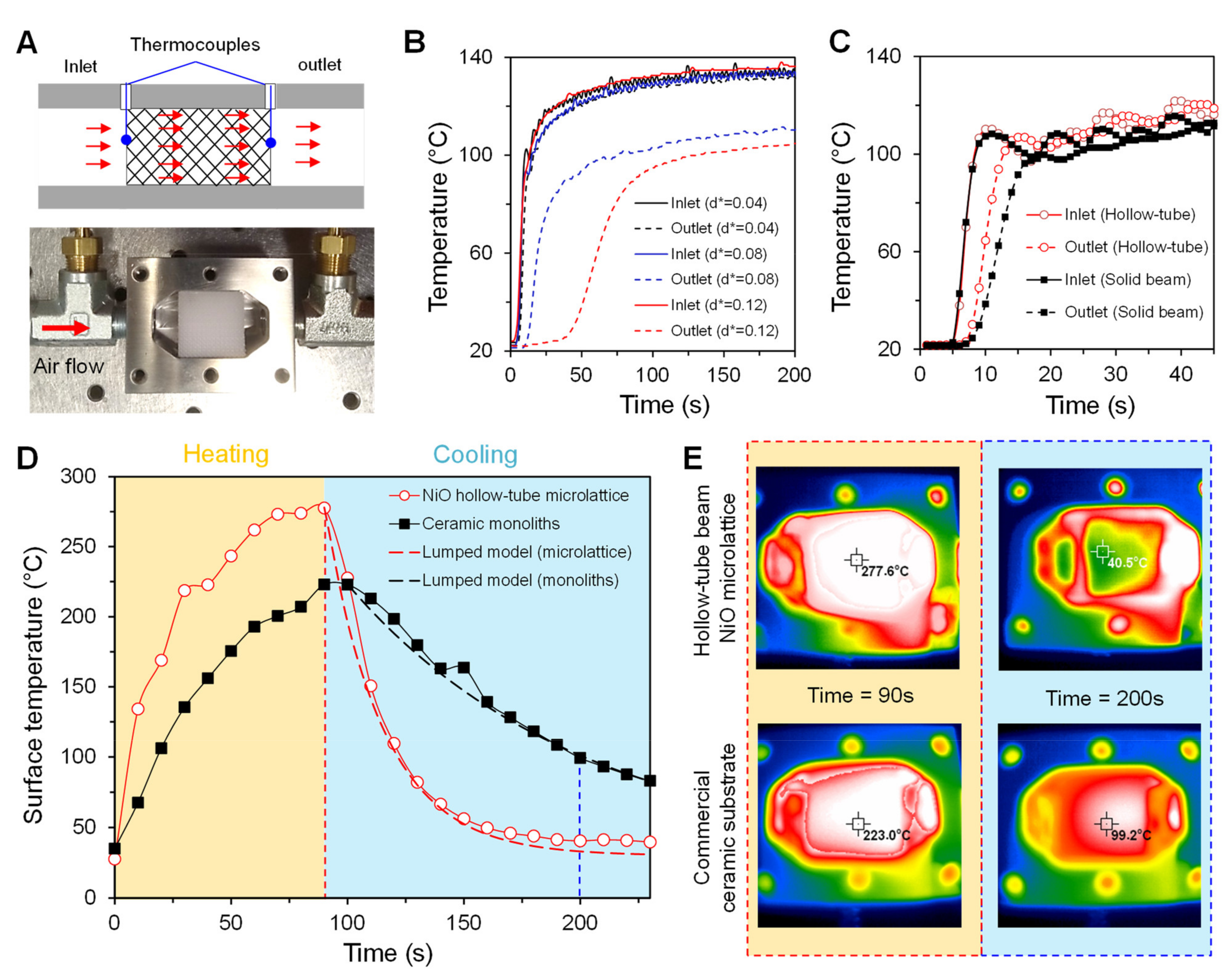
2.5. Measurement of the Thermal Response

The geometrical effect on the thermal response was studied by placing polymeric 3D microlattices (beam diameter: 100 μm) and square-type monoliths (wall thickness: 100 μm) with an overall size of 20 × 20 × 30 mm3 in a small-scale test chamber with identical interior dimensions. We used an adjustable industrial heat gun with a temperature range of 49–927 °C and a flow rate up to 18 cubic feet per minute (CFM) to simulate the forced convection flow. Two Cr-Ni alloy type K-type thermocouples were used to measure the temperature at the inlet and outlet of the printed substrates under air flow at a rate of 21.24 L/min. These were located along the central region of the printed substrates, where the influence of the test chamber wall was negligible. The substrates were wrapped in a ceramic mat or thin quartz glass to prevent flow bypass. Such materials were assumed to have a negligible influence on the heat transfer measurements in the structure owing to their low thermal conductivities. Owing to the fabrication capability of the Ni-P plating and thermal annealing process, samples with an overall size of 20 mm × 20 mm × 20 mm were used to measure the thermal response of the microlattice samples with solid beams and hollow tubes. The thermal response of microarchitected reactors at high temperatures was measured by recording the temperature of the surface using a thermal imaging camera in the same small-scale chamber with input flow velocity of 5 m/s at a temperature of 650 °C. To verify the high-temperature resistance of ceramic microarchitectures, the optical images of the NiO hollow-tube microlattice and conventional ceramic monoliths (Corning cordierite monoliths, 17 cells per inch, wall thickness: 300 μm) were recorded under a butane blowtorch flame, which is known to have a flame temperature up to 1430 °C.

2.6. CFD Simulation

Numerical studies were performed using COMSOL Multiphysics 5.6. to estimate the fluidic distribution inside the 3D microlattice and monolith channel structures. The computational domain consisted of a fluid domain for fluid flow and ceramic substrate domain whose sizes were 7.81 mm (length) × 3.81 mm (width) × 3.81 mm (height) and 3.81 mm × 3.81 mm × 3.81 mm, respectively. The unit cell size of octet-truss lattice and monolith is 1.27 mm × 1.27 mm × 1.27 mm with strut diameter and wall thickness of 100 μm. In our CFD simulation, air and alumina were assumed as the working fluid and ceramic substrate, respectively. The initial temperature of the substrate region was set at 27 °C. Under the no-slip and symmetry boundary conditions, the input velocity and temperature inside the 3D structures were set as 1 m/s and 927 °C, respectively. The initial temperatures of the fluid domain and ceramic substrate domain were set to 27 °C. To check the thermal response of each substrate, thermal flow analysis was conducted assuming a time-dependent process. Also, the fluid flow was assumed to be incompressible and the standard k–ε model was used because the flow upstream and downstream of the 3D structures was turbulent [20]. The specific heat and other thermodynamic properties such as the density of air and alumina were calculated using the COMSOL database.

3. Results

3.1. Design Concept

The physical properties of 3D microarchitected reactors, such as mechanical, thermal, or chemical responses, are determined by the unit cell geometry, relative density, and constituent materials. Microstructural properties linked to reactor performance include chemically related morphological properties, such as the surface area, and physical properties, such as the relative density, related to heat capacity, which controls thermal transport. Efficient thermal and mass transport through 3D microarchitectures requires a low heat capacity and high surface area, which lead to enhanced chemical and biological reactions, including catalysis, ion exchange, mass transport, and cell-scaffold interactions at the surface [8]. As the heat capacity is a function of the relative density (ρr), a higher surface-area-to-density ratio is required to provide better catalytic and biological reactor architectures for efficient reaction performance. In this study, we explore octet-truss microlattice networks with solid and hollow tube beams, of which the cross-sectional diameter, wall thickness, and unit cell length are d, t, and l, respectively (Figure 1A). Here, the dimensionless beam diameter (d* = d/l) and wall thickness (t* = t/d) were selected to investigate the theoretical geometric quantities of the relative density ρr and specific surface area SA, defined by the lattice surface area over the total geometric volume (l3), for the octet-truss microlattice with solid and hollow tube beams. The specific surface area SA was also scaled by the unit cell length to obtain a dimensionless form (SA* = SA·l). In octet-truss lattices with solid beams, the approximate analytical equations for the relative density and specific surface area are given by 3 2 π d * 2 and 12 2 π d * , respectively [21]. However, this simple estimation, which is based on a first-order approximation, overestimates the relative density owing to double counting of the volume and surface of the intersections between nodes. For small d*, the effect of nodal intersection terms is negligible, but as d* increases, nodal interference has a greater effect on the relative density and surface area, which leads to inaccurate estimation [21,22,23]. Hence, at high relative densities, the complex geometry of nodal intersections must be considered when calculating ρr and SA*. Accounting for the sum of the nodal effects, higher-order approximations of ρr and SA* are given by:
ρ r = 3 2 π d * 2 C 1 d * 3 ,
S A * = 12 2 π d * C 2 d * 2 2
C1 and C2 were 19.3 and 163.8, respectively, depending on the detailed geometry of the nodes [21,22]. These geometric constants can also be calculated using CAD software by curve fitting ρr and SA*. Three-dimensional microlattices with hollow tube beams require the correction factors for a hollow cylinder and sphere, which are given by f t * = 4 t * + 4 t * 2 and g t * = 6 t * + 12 t * 2 + 8 t * 3 , respectively [23]. Considering the effects of nodal interference, we obtained the following modified equations for ρr and SA* of the hollow tube microlattice:
ρ r = 3 2 π d * 2 f t * C 1 d * 3 g t * ,
S A * = 24 2 π d * + d * t * C 2 d * 2 2 + d * 2 t * 1 + t *
The plot of the relative density of each microlattice as a function of d* (Figure 1B) confirms that the hollow tube microlattices exhibit an ultralow relative density, enabling a lower heat capacity owing to their tubular geometry and high porosity. Because of the inner and outer surface areas of the tubular geometry, the hollow microlattice network increases the surface area of substrates independent of the pressure drop, compared to solid beam microlattice geometries. The coupling of the morphological and physical properties of each microlattice was considered by analyzing the dimensionless parameter of SA* as a function of d* and t* (Figure 1C,D). The hollow microlattice structure allows the simultaneous flow and homogeneous redistribution of working fluids in the inner and outer surfaces separated by tubular walls, which provides higher heat transfer performance by employing a higher specific surface area-to-relative density ratio (SA*/ρr) [19].

3.2. Fabrication of Hollow Microlattices

The fabrication process of the hollow microlattices includes 3D additive manufacturing, conformal coating of composite electroless plating, polymer template removal, and thermal annealing, as illustrated in Figure 2. The polymer 3D microlattice template with strut diameter d = 100 μm was first printed by projection microstereolithography (Figure 2A) and then conformally coated with a nickel–phosphorus (Ni-P) metallic material by electroless plating (Figure 2C). Instead of directly fabricating the tube walls, conformal coating of the secondary material onto the sacrificial polymer template provides some benefits for fabricating the 3D hollow-tube microlattices described in this study. First, the minimum thickness of the tube wall can be significantly reduced relative to the minimum feature size of the conventional 3D printing process. Second, conformal coating methods allow for a variety of material combinations, including metals, ceramics, and polymers, on sacrificial polymeric scaffolds [1]. Moreover, as a mature technology with low cost, conformal coating facilitates the production of complex hollow microarchitectures over large areas. In this study, we controlled the Ni-P thickness by varying the plating time, which is known for enabling metal films from several hundreds of nanometers to tens of micrometers [24]. Then, the polymer template was completely removed by heat treatment to form the hollow tubular structure. Finally, thermal annealing in air at 927 °C converted metallic Ni-P to nickel oxide (NiO), as shown in Figure 2C–E. After characterization using scanning electron microscopy (SEM) and energy-dispersive X-ray spectrometry (EDS), we confirmed that a hollow-tube ceramic microlattice was fabricated with a NiO μm wall thickness t of the NiO layer (Figure 2D). EDS results showed that the layer comprised 62.29% Ni and 31.37% O (Figure 2E). Here, a small amount of C may be derived from the polymer constituents of the polymeric microlattices.

3.3. Fluidic Properties

In this study, the hydraulic performance of a 3D microlattice was analyzed based on the pressure drop, Δp, and flow distribution. Figure 3 shows the measured pressure drop between the inlet and outlet of the 3D microlattices, depending on the flow rate and d*. Owing to the complex geometric effect of multiple beams and nodes inside the microlattice structures [25,26,27], the pressure drop of the microlattices monotonically increases and follows a quadratic dependence as a function of the flow rate (Figure 3B). This quadratic behavior of the pressure drop depending on the flow rate can be explained by the Forchheimer-extended Darcy equation, as shown in Equation (5) [28,29].
Δ p L = μ / K 1 u + ( ρ f / K 2 ) u 2  
where Δp/L, μ, u, and ρf represent the pressure drop per overall sample length L, dynamic viscosity of the fluid flowing through the microlattices, flow velocity, and density of the fluid, respectively, while K1 and K2 are the Darcian and non-Darcian permeabilities, respectively. According to the correlation proposed by Ergun and Orning, the permeabilities in the Forchheimer-extended Darcy equation can be described by Equation (6), which considers the geometric parameters of specific surface area SA and porosity ε (=1 − ρr) [30].
Δ p L = α μ 1 ε 2 S A 2 ε 3 u + β ρ f 1 ε S A ε 3 u 2  
where α and β are the Ergun parameters of the viscous and inertial terms, respectively. Consequently, as d* increases, the increased surface area and decreased porosity in the 3D microlattices with solid beams yield a higher pressure drop, as shown in Figure 3B. Moreover, we clearly observed that there is little difference in the pressure drop between the hollow tube and solid beam microlattice (Figure 3C), which strongly supports our argument that the hollow microlattice is capable of increasing the effective surface area independent of the pressure drop compared to solid beam microlattice geometries.
In addition to providing a more active wall and surface area inside the structure via 3D hollow microlattices, the engineered 3D microlattice structures can redistribute the flow of working fluids and enhance the mass and heat transport through the solid interface. Enhanced mixing of fluid flow inside 3D lattice structures improved the heat and mass transport characterized by significantly higher Nusselt and Sherwood numbers compared with laminar flow inside monolith channels [8,31,32]. To understand the fluidic distribution inside the architected porous materials, we visualized the fluid flow using CFD simulations and thermal imaging measurements. The CFD simulations (Figure 3D,E) indicate that while the fluid flow of the monolith channels becomes laminar, the 3D microlattices allow homogeneous radial mixing of the flow and create turbulence-like conditions inside the structures. In terms of the flow field, the main difference between the monolith channel and 3D microlattice structure is that the monolith does not allow any momentum exchange perpendicular to the main flow direction, whereas the 3D microlattice allows the working fluids to flow in all directions through it (thermal imaging in Figure 3D,E). Figure 3D,E show the thermal images of the polymeric 3D microlattice and monolith channels, respectively. Both structures were heated using an adjustable industrial heat gun at a temperature of 120 °C and subjected to a flow rate of 21.24 L/min. The thermal imaging results show that the microlattice provides a homogeneous distribution along the direction of hot air flow compared to the monolith channels, which demonstrates that the geometry provides improved thermal distribution away from the heated surface. Diffusion is dominant for transport from the working fluid to the active solid interface owing to the laminar flow developed inside the monolith channel, and may result in relatively poor transfer conditions [8]. Although the monolith channel can exhibit a relatively low pressure drop, most fluids pass through the channel structure without reacting because of their high flow rates. Hence, we introduced 3D microarchitectures in this work to enhance surface transport by transforming laminar to turbulent flow and promoting transverse mixing inside the periodic lattice geometry.

3.4. Thermal Properties

To further study the geometrical effect on the thermal response, we measured the inlet and outlet temperatures of the printed 3D microlattices in a small-scale chamber using air flowing at a temperature of 120 °C through the inlet (Figure 4A). The inlet temperatures are nearly identical, and the outlet temperature increases with a time delay corresponding to the transient thermal response, which is proportional to the heat capacity and pressure drop. Here, we observed that the time for the temperature to stabilize at the outlet increases as d* increases (Figure 4B), possibly owing to the slow thermal response because of the increased heat capacity and pressure drop. Moreover, the microlattice with hollow-tube beams approaches the steady-state temperature faster than that with solid beams (Figure 4C). Because these microlattices exhibit almost the same pressure drop behavior owing to the same geometric value of d*, as already shown in Figure 3C, it is reasonable that the low volumetric heat capacity that is due to the hollow-tube geometry enables a faster thermal response of the microarchitected materials. Considering higher temperature applications, the surface temperature and thermal distribution of NiO-based ceramic hollow microlattices and conventional ceramic monoliths were also investigated using a thermal imaging camera in a small-scale test chamber at a temperature of 650 °C under air flow conditions (Figure 4D,E). After heating for 90 s, the samples begin to cool simultaneously in the atmosphere. The NiO-based hollow microlattice approaches a saturated temperature faster than commercial ceramic monoliths (Figure 4D,E). The temperature of the microlattice is lowered faster than that of the monolith, demonstrating that the hollow-tube geometry provides a low thermal mass to enable a faster thermal response.

4. Discussion

In this study, we explain the faster thermal response of hollow ceramic microlattices by utilizing a dimensionless quantity known as the Biot number (Bi = hfluidt/kwall), which is defined as the ratio of the rate of convection in working fluids to the rate of conduction through the solid interface [12,33]. Here, hfluid and kwall represent the heat transfer coefficient of the working fluid and thermal conductivity of the hollow tube wall material, respectively. Assuming a fully developed flow around the hollow tube structures with constant heat flux at the walls, the Nusselt number (Nu = hfluid(D + 2t)/kfluid) is 4.36. It is to be noted that the Nusselt number is defined as the ratio of convective to conductive heat transfer at the fluid–solid boundary, where kfluid is the thermal conductivity of the working fluid [12]. For the dimensional analysis of thermal transport in hollow-tube geometry, we can extract the relationship between the Biot number, interfacial thickness-to-beam diameter (t*) ratio, and fluid-interfacial material combination.
Bi = 4.36 2 + 1 t * 1 k fluid k wall
The Biot number should be less than 0.1 (preferably <0.01) to ensure that heat transfer through the interfacial walls does not dominate the overall heat transfer rate. For a given fluid–solid interface combination, this relationship can provide an estimation of the Biot number as a function of t*, which is used to provide dynamic similitude in different fluid flow situations. Considering thermal conductivities of air (kair = 0.03 W/mK), water (kwater = 0.58 W/mK), and NiO (kNiO = 5 W/mK above 750 K [34]), the Biot number in the NiO hollow-tube beam was estimated to be approximately 0.002 and 0.04 under the flow of air and water, respectively. This suggests that the fabricated NiO hollow-tube microlattice can be regarded as a ‘thermally thin’ structure, which supports our understanding of the rapid thermal response shown in Figure 4.
To simplify the theoretical analysis and quantify the experimental results, we further discuss lumped system analysis considering a homogeneously heated object, which can be described by a small Biot number (Bi << 1) [35,36]. For comparison, the Biot number of the commercial ceramic monoliths was also assumed to be small because the channel wall thickness of 300 μm was relatively small. Furthermore, under a uniform volumetric heat source, the temperature of the object in the transient state can be analyzed as a function of time only, which greatly simplifies certain classes of heat transfer problems without sacrificing accuracy. If the heated object is placed and cooled in air, we assumed typical values for the heat transfer coefficients (hfluid) for free convection (solids to gases) in the range 2–25 W (m2K)−1 [35]. After heating for 90 s, the heated objects were placed in a medium at temperature Tsurr (assuming an air temperature of 30 °C), and heat transfer occurred between the object and its environment, with a heat transfer coefficient hfluid. Based on the lumped system analysis, we can assume that the temperature remains uniform within the object at all times and varies only with time, T = T(t). Accordingly, despite the nonlinearity of the complete heat transfer equation owing to the radiative term, the physical cooling of the heated object can be reasonably described as the exponential function in Equation (8). The cooling profiles of the measured surface temperatures for the hollow microlattice and ceramic monoliths also showed a good fit with the following equation, as presented in Figure 4D.
T t = T surr + ( T i T surr ) · e t τ   with   time   constant   τ = c p ρ r ρ s / h fluid S A ,  
where cp and ρs are the specific heat capacity and density of the constituent materials, respectively, while the fitting values of the time constant τ were approximately 25 s and approximately 100 s for the hollow NiO microlattice and ceramic monoliths, respectively. The temperature of the objects approaches the ambient temperature Tsurr exponentially, and a smaller value of the exponent τ corresponds to a higher rate of decay in temperature. Because τ is proportional to the relative density and heat capacity and inversely proportional to the specific surface area, it strongly supports the rapid thermal response characteristic of the NiO hollow tube microlattice because of the low heat capacity.
To further investigate the thermofluidic efficiency of the 3D microarchitected reactors, we deduced the analytic relationship between the dimensionless friction factor f and thermal time constant τ as a function of the relative density ρr. The pressure drop in 3D microlattices (Equation (6)) can be approximated as the reduced model to analyze the correlation between f and τ in this study [13,32]:
Δ p L     β ρ f ρ r S A 1 ρ r 3 u 2
The friction factor, which is used to quantify the flow resistance across 3D cellular materials, is defined as:
f = Δ p L 2 D h ρ f · u 2
where Dh, the hydraulic diameter of the 3D microlattice, is defined as 4 l 1 ρ r / C A . The dimensionless coefficient CA depends on the shape of the unit cell [31,37]. Then, we can derive the correlation between the pressure drops and friction factor as:
f = β ρ r S A 1 ρ r 3 2 D h = 4 β l C A ρ r S A 1 ρ r 1 ρ r 3 = 4 β l C A ρ r S A 1 ρ r 2.5 .
Considering Equation (8), the correlation between f and τ can be described as follows:
f · τ = 4 β l C A · c p ρ s h fluid ρ r 2 1 ρ r 2.5   ~   C · ρ r 2 1 ρ r 2.5 .
The map of f·τ can be considered as the design criteria for 3D microlattice-based reactors in this study. The specifics are manifested in cross plots of the friction factor and time constant indices, as shown in Figure 5. The relationship f·τ ~ C·ρr2/(1 − ρr)2.5 is obtained based on theoretical analysis by the above modeling and empirical behavior of the thermal response and pressure drop as the relative density of the microlattices. C is the thermophysical constant corresponding to unknown numerical coefficients that reflect the physical properties of the constituent materials. It is to be noted that owing to the various physical parameters involved, these maps have been plotted depending on the constant relative densities, and these analytic f·τ boundaries are denoted by solid lines in Figure 5. When the designs are limited by the relative density, the opportunities for f to the pressure drop are configured with τ specific to the thermal response. These results reveal that the thermofluidic properties of low thermal mass and flow resistance are more evident in low-density structures. Furthermore, the hollow microlattices provide the added benefit of tunable thermofluidic properties by only changing the relative density, which can decouple the thermal properties from the fluidic properties without affecting the flow resistance.
In addition, the hollow tube NiO microlattice exhibited excellent heat resistance after exposure to high-temperature flames. As shown in Figure 6, the time-dependent high-temperature resistance properties of the NiO microlattice and commercial ceramic monoliths were further characterized by recording the optical images when the samples were subjected to a butane blowtorch flame. The temperature of the butane flame is known to reach approximately 1430 °C, and we confirmed that the hollow-tube NiO microlattices were thermally stable at high temperatures. Owing to the low heat capacity and Biot number, we clearly observed that the hollow 3D microlattice exhibited a rapid cooling performance compared to the ceramic monolith structure.

5. Conclusions

The advances in recently developed technology for printing functional structures have generated new possibilities for optimizing 3D microreactors for thermal and fluid applications. Complex 3D internal geometries provide the possibility of increasing the effectiveness of chemical or biological reactions while maintaining the pressure drop within practical limits. In this regard, we demonstrated 3D microarchitected ceramic reactors with low heat capacity proportional to the relative density by leveraging the geometric benefits of lattice networks comprising hollow-tube beams that enable high-temperature operation of ~1400 °C. In this study, we utilized the octet-based hollow microlattice as a model structure to investigate the thermal and fluidic behavior of low-heat-capacity microarchitected reactors. Based on the analytic calculations, we first confirmed the geometrical benefits of the hollow microlattice, which increased the surface area while maintaining low weight. Then, experimental studies and computational analysis demonstrated that this lightweight 3D microlattice enabled rapid thermal response with a small Biot number (Bi << 1) and flow redistribution in working fluids. Finally, to further support our arguments, we discussed the lumped models for transient thermal analysis of our proposed low-heat-capacity hollow ceramic microarchitectures. Based on the findings in this work, we envision that our approach will lead to the development of new design methodologies for integrating microarchitected reactor geometries and functional materials to achieve improved performance through devices and products related to heat–mass transfer properties, including catalytic supports [5], flow-through electrodes [7], and photobioreactors [38].

Author Contributions

Conceptualization, S.K. (Seok Kim) and N.X.F.; methodology, S.K. (Seok Kim); software, S.K. (Seok Kim); validation, S.K. (Seok Kim) and N.X.F.; formal analysis, S.K. (Seok Kim), S.-H.N., S.K. (Seokho Kim), Y.T.C., N.X.F.; investigation, S.K. (Seok Kim); resources, S.K. (Seok Kim); data curation, S.K. (Seok Kim); writing—original draft preparation, S.K. (Seok Kim); writing—review and editing, S.K. (Seok Kim), S.-H.N., S.K. (Seokho Kim), Y.T.C., N.X.F.; visualization, S.K. (Seok Kim); supervision, S.K. (Seok Kim) and N.X.F.; project administration, S.K. (Seok Kim) and N.X.F.; funding acquisition, S.K. (Seok Kim), S.K. (Seokho Kim), Y.T.C. All authors have read and agreed to the published version of the manuscript.

Funding

This research was supported by a National Research Foundation of Korea (NRF) grant funded by the Korean government (MSIT) (No. 2019R1A5A8083201 and 2022R1C1C1003966).

Data Availability Statement

The data used in this work can be made available by contacting Seok Kim at [email protected] or Nicholas X. Fang at [email protected].

Conflicts of Interest

The authors declare no conflict of interest.

Nomenclature

ρrThe relative density
dThe diameter
tThe wall thickness
lThe unit cell length
d*The dimensionless diameter (= d/l)
t*The wall thickness (= t/d)
SAThe specific surface area
SA*The dimensionless form surface area (= SA·l)
SA*rThe specific surface area-to-relative-density ratio
ΔpThe pressure drop
LThe overall sample length
μThe dynamic viscosity of the fluid
uThe flow velocity
ρfThe density of the fluid
K1The Darcian permeability
K2The non-Darcian permeability
εThe porosity (= 1 − ρr)
αThe Ergun parameter of the viscous term
βThe Ergun parameter of the inertial term
Bi The Biot number
hfluidThe heat transfer coefficient of the working fluid
kwallThe thermal conductivity of the hollow tube wall material
kfluidThe thermal conductivity of the working fluid
NuThe Nusselt number
cpThe specific heat capacity and density of the constituent materials
ρsThe density of the constituent materials
TsurrThe ambient temperature
fThe dimensionless friction factor
τThe thermal time constant
DhThe hydraulic diameter of the 3D microlattice
CAThe dimensionless coefficient depends on the shape of the unit cell
CThe thermophysical constant corresponding to unknown numerical coefficients

References

  1. Schaedler, T.A.; Carter, W.B. Architected Cellular Materials. Annu. Rev. Mater. Res. 2016, 46, 187–210. [Google Scholar] [CrossRef]
  2. Thakkar, H.; Eastman, S.; Hajari, A.; Rownaghi, A.A.; Knox, J.C.; Rezaei, F. 3D-Printed Zeolite Monoliths for CO2 Removal from Enclosed Environments. ACS Appl. Mater. Interfaces 2016, 8, 27753–27761. [Google Scholar] [CrossRef] [PubMed]
  3. Ruiz-Morales, J.C.; Tarancon, A.; Canales-Vazquez, J.; Mendez-Ramos, J.; Hernandez-Afonso, L.; Acosta-Mora, P.; Marin Ruedac, J.R.; Fernandez-Gonzalez, R. Three dimensional printing of components and functional devices for energy and environmental applications. Energy Environ. Sci. 2017, 10, 846–859. [Google Scholar] [CrossRef] [Green Version]
  4. Weng, J.; Lu, X.; Gao, P.X. Nano-Array Integrated Structured Catalysts: A New Paradigm upon Conventional Wash-Coated Monolithic Catalysts? Catalysts 2017, 7, 253. [Google Scholar] [CrossRef] [Green Version]
  5. Zhu, C.; Qi, Z.; Beck, V.A.; Luneau, M.; Lattimer, J.; Chen, W.; Biener, J. Toward digitally controlled catalyst architectures: Hierarchical nanoporous gold via 3D printing. Sci. Adv. 2018, 4, eaas9459. [Google Scholar] [CrossRef] [Green Version]
  6. Blanchette, C.D.; Knipe, J.M.; Stolaroff, J.K.; DeOtte, J.R.; Oakdale, J.S.; Maiti, A.; Baker, S.E. Printable enzyme-embedded materials for methane to methanol conversion. Nat. Commun. 2016, 7, 11900. [Google Scholar] [CrossRef] [Green Version]
  7. Beck, V.A.; Ivanovskaya, A.N.; Chandrasekaran, S.; Forien, J.B.; Baker, S.E.; Duoss, E.B.; Worsley, M.A. Inertially enhanced mass transport using 3D-printed porous flow-through electrodes with periodic lattice structures. Proc. Natl. Acad. Sci. USA 2021, 118, 32. [Google Scholar] [CrossRef]
  8. Kim, S.; Kim, D.H.; Kim, W.; Cho, Y.T.; Fang, N.X. Additive manufacturing of functional microarchitected reactors for energy, environmental, and biological applications. Int. J. Precis. Eng. Manuf.-Green Technol. 2021, 8, 303–326. [Google Scholar] [CrossRef]
  9. Ma, C.; Kim, S.; Fang, N.X. Far-field acoustic subwavelength imaging and edge detection based on spatial filtering and wave vector conversion. Nat. Commun. 2019, 10, 204. [Google Scholar] [CrossRef]
  10. Steiner, T.; Neurauter, D.; Moewius, P.; Pfeifer, C.; Schallhart, V.; Moeltner, L. Heat-Up Performance of Catalyst Carriers—A Parameter Study and Thermodynamic Analysis. Energies 2021, 14, 964. [Google Scholar] [CrossRef]
  11. Kim, S.; Handler, J.J.; Cho, Y.T.; Barbastathis, G.; Fang, N.X. Scalable 3D printing of aperiodic cellular structures by rotational stacking of integral image formation. Sci. Adv. 2021, 7, eabh1200. [Google Scholar] [CrossRef] [PubMed]
  12. Roper, C.S.; Schubert, R.C.; Maloney, K.J.; Page, D.; Ro, C.J.; Yang, S.S.; Jacobsen, A.J. Scalable 3D bicontinuous fluid networks: Polymer heat exchangers toward artificial organs. Adv. Mater. 2015, 27, 2479–2484. [Google Scholar] [CrossRef] [PubMed]
  13. Woodward, I.R.; Attia, L.; Patel, P.; Fromen, C.A. Scalable 3D-printed lattices for pressure control in fluid applications. AIChE J. 2021, 67, e17452. [Google Scholar] [CrossRef] [PubMed]
  14. Sinn, C.; Wentrup, J.; Pesch, G.R.; Thöming, J.; Kiewidt, L. Structure-heat transport analysis of periodic open-cell foams to be used as catalyst carriers. Chem. Eng. Res. Des. 2021, 166, 209–219. [Google Scholar] [CrossRef]
  15. Takarazawa, S.; Ushijima, K.; Fleischhauer, R.; Kato, J.; Terada, K.; Cantwell, W.J.; Hasumoto, S. Heat-transfer and pressure drop characteristics of micro-lattice materials fabricated by selective laser metal melting technology. Heat Mass Transf. 2022, 58, 125–141. [Google Scholar] [CrossRef]
  16. García-Vázquez, M.; Zhang, G.; Hong, Z.; Gu, X.; Garcia-Garcia, F.R. Micro-structured catalytic converter for residual methane emission abatement. Chem. Eng. J. 2020, 396, 125379. [Google Scholar] [CrossRef]
  17. Narkhede, S.; Sur, A. Performance prediction of hollow micro-lattice cross-flow heat exchanger using a numerical approach. Int. J. Ambient. Energy 2021, 1–8. [Google Scholar] [CrossRef]
  18. Mazzone, S.; Campbell, A.; Zhang, G.; García-García, F.R. Ammonia cracking hollow fibre converter for on-board hydrogen production. Int. J. Hydrog. Energy 2021, 46, 37697–37704. [Google Scholar] [CrossRef]
  19. Xu, W.; Liu, L.; Chen, J.; Lv, X.; Yao, Y. A hollow microlattice based ultralight active thermal control device and its fabrication techniques and thermal performances. J. Micromech. Microeng. 2021, 32, 015010. [Google Scholar] [CrossRef]
  20. Oskooei, A.B.; Koohsorkhi, J.; Mehrpooya, M. Simulation of plasma-assisted catalytic reduction of NOx, CO, and HC from diesel engine exhaust with COMSOL. Chem. Eng. Sci. 2019, 197, 135–149. [Google Scholar] [CrossRef]
  21. Deshpande, V.S.; Fleck, N.A.; Ashby, M.F. Effective properties of the octet-truss lattice material. J. Mech. Phys. Solids 2001, 49, 1747–1769. [Google Scholar] [CrossRef] [Green Version]
  22. Tancogne-Dejean, T.; Spierings, A.B.; Mohr, D. Additively-manufactured metallic micro-lattice materials for high specific energy absorption under static and dynamic loading. Acta Mater. 2016, 116, 14–28. [Google Scholar] [CrossRef]
  23. Meza, L.R.; Phlipot, G.P.; Portela, C.M.; Maggi, A.; Montemayor, L.C.; Comella, A.; Kochmann, D.M.; Greer, J.R. Reexamining the mechanical property space of three-dimensional lattice architectures. Acta Mater. 2017, 140, 424–432. [Google Scholar] [CrossRef] [Green Version]
  24. Zheng, X.; Lee, H.; Weisgraber, T.H.; Shusteff, M.; DeOtte, J.; Duoss, E.B.; Kuntz, J.D.; Biener, M.M.; Ge, Q.; Jackson, J.A.; et al. Ultralight, ultrastiff mechanical metamaterials. Science 2014, 344, 1373. [Google Scholar] [CrossRef] [PubMed] [Green Version]
  25. Fink, K.D.; Kolodziejska, J.A.; Jacobsen, A.J.; Roper, C.S. Fluid dynamics of flow through microscale lattice structures formed from self-propagating photopolymer waveguides. AICHE J. 2011, 57, 2636–2646. [Google Scholar] [CrossRef]
  26. Roper, C.S.; Fink, K.D.; Lee, S.T.; Kolodziejska, J.A.; Jacobsen, A.J. Anisotropic convective heat transfer in microlattice materials. AIChE J. 2013, 59, 622–629. [Google Scholar] [CrossRef]
  27. Maloney, K.J.; Fink, K.D.; Schaedler, T.A.; Kolodziejska, J.A.; Jacobsen, A.J.; Roper, C.S. Multifunctional heat exchangers derived from three-dimensional micro-lattice structures. Int. J. Heat Mass Transf. 2012, 55, 2486. [Google Scholar] [CrossRef]
  28. Edouard, D.; Lacroix, M.; Huu, C.P.; Luck, F. Pressure drop modeling on SOLID foam: State-of-the art correlation. Chem. Eng. J. 2008, 144, 299–311. [Google Scholar] [CrossRef]
  29. Chaudhari, A.; Ekade, P.; Krishnan, S. Experimental investigation of heat transfer and fluid flow in octet-truss lattice geometry. Int. J. Therm. Sci. 2019, 143, 64–75. [Google Scholar] [CrossRef]
  30. Inayat, A.; Klumpp, M.; Lämmermann, M.; Freund, H.; Schwieger, W. Development of a new pressure drop correlation for open-cell foams based completely on theoretical grounds: Taking into account strut shape and geometric tortuosity. Chem. Eng. J. 2016, 287, 704–719. [Google Scholar] [CrossRef]
  31. Lu, T.J.; Valdevit, L.; Evans, A.G. Active cooling by metallic sandwich structures with periodic cores. Prog. Mater. Sci. 2005, 50, 789–815. [Google Scholar] [CrossRef]
  32. Lucci, F.; Della Torre, A.; Montenegro, G.; Eggenschwiler, P.D. On the catalytic performance of open cell structures versus honeycombs. Chem. Eng. J. 2015, 264, 514–521. [Google Scholar] [CrossRef]
  33. Dewitt, D.; Bergman, T.; Lavine, A. Fundamentals of Heat and Mass Transfer; Wiley: Hoboken, NJ, USA, 2007. [Google Scholar]
  34. Pranati Sahoo, P.; Misra, D.K.; Salvador, J.; Makongo, J.P.A.; Chaubey, G.S.; Takas, N.J.; Wiley, J.B.; Poudeu, P.F.P. Microstructure and thermal conductivity of surfactant-free NiO nanostructures. J. Solid State Chem. 2012, 190, 29–35. [Google Scholar] [CrossRef]
  35. Vollmer, M. Newton’s law of cooling revisited. Eur. J. Phys. 2009, 30, 1063. [Google Scholar] [CrossRef]
  36. Gómez-Gómez, A.; Moyano, J.J.; Román-Manso, B.; Belmonte, M.; Miranzo, P.; Osendi, M.I. Highly-porous hierarchical SiC structures obtained by filament printing and partial sintering. J. Eur. Ceram. Soc. 2019, 39, 688–695. [Google Scholar] [CrossRef]
  37. Gu, S.; Lu, T.J.; Evans, A.G. On the design of two-dimensional cellular metals for combined heat dissipation and structural load capacity. Int. J. Heat Mass Transf. 2001, 44, 2163–2175. [Google Scholar] [CrossRef]
  38. Pires, J.C.; Alvim-Ferraz, M.C.; Martins, F.G. Photobioreactor design for microalgae production through computational fluid dynamics: A review. Renew. Sustain. Energy Rev. 2017, 79, 248–254. [Google Scholar] [CrossRef]
Figure 1. (A) Schematics of 3D microlattices with solid and hollow-tube beams. (BD) Relative density (ρr) and dimensionless surface area (SA*) of the solid and hollow-tube beam microlattices as a function of d* and t*, respectively.
Energies 15 04073 g001
Figure 2. Fabrication of the microlattice with hollow-tube networks. (A) Polymeric microlattice fabricated by DLP 3D printing process. (B) Solid Ni-P/polymer composite microlattices (d* = 0.08). (C) NiO-based hollow-tube ceramic microlattices (d* = 0.08 and t* = 0.1). (D) Magnified views of the hollow-tubes of the ceramic microlattices. (E) Measured EDS of the hollow-tube NiO microlattices.
Energies 15 04073 g002
Figure 3. (A) Schematic of the test setup. Pressure drop of the polymer microlattice with solid beams (B) and hollow-tube ceramic microlattices (C). Flow distribution of the 3D microlattice (D) and monolith structure (E).
Energies 15 04073 g003
Figure 4. (A) Thermal response of microarchitectures with various configurations and constituent materials. (B) Polymeric microlattice with solid beams (d* = 0.04, 0.08, and 0.12), and (C) hollow-tube ceramic microlattice and solid Ni-P/polymer composite microlattice (d* = 0.08 and t* = 0.1). (D) Surficial temperature and (E) thermal distribution of hollow NiO microlattice and ceramic monoliths at heating condition by hot air flowing and cooling condition in the atmosphere.
Energies 15 04073 g004
Figure 5. Figure of merit for the relationship f·τ. The friction factor f subjected to a pressure drop was plotted as a function of the time constant τ at various relative densities.
Energies 15 04073 g005
Figure 6. Optical images of hollow-tube NiO microlattices and conventional ceramic monolith subjected to the butane blowtorch flame.
Energies 15 04073 g006
Publisher’s Note: MDPI stays neutral with regard to jurisdictional claims in published maps and institutional affiliations.

