Article

Magnetic Field Analysis of an Inner-Mounted Permanent Magnet Synchronous Motor for New Energy Vehicles

1
School of Transportation and Vehicle Engineering, Shandong University of Technology, Zibo 255049, China
2
Technology Center, Weifang No. 1 Motor Factory Co., Ltd., Weifang 262127, China
3
Research and Development Center, Shandong Hapuwo Power Technology Co., Ltd., Zibo 255300, China
*
Author to whom correspondence should be addressed.
Energies 2022, 15(11), 4074; https://doi.org/10.3390/en15114074
Submission received: 4 May 2022 / Revised: 24 May 2022 / Accepted: 26 May 2022 / Published: 1 June 2022
(This article belongs to the Section E: Electric Vehicles)

Abstract

:
The motor is an important component that affects the output performance of new energy vehicles (using new energy sources such as electric energy and hydrogen fuel energy to drive the motor and provide kinetic energy). Motors with high power and low noise can effectively improve the dynamic performance, passability and smoothness of new energy vehicles and bring a comfortable experience to driver and passengers. The magnetic field analytical model of the inner-mounted permanent magnet synchronous motor (IPMSM) is studied to improve its output quality. The motor is divided into four subdomains: the stator slot subdomain, the stator slot notch subdomain, the air-gap subdomain, and the permanent magnet (PM) subdomain. The general solution of the vector magnetic potential of each subdomain is solved, and the expression of magnetic flux density of each subdomain is derived. Meanwhile, the analytical model of the non-uniform air gap is established according to the uniform air-gap model. The model’s accuracy is verified by finite element analysis and prototype tests. The results show that the calculation results of the analytical model are effective. The model can be applied to predict the no-load back electromotive force (EMF) and cogging torque of the motor under different main air gaps. It also provides an effective and fast analysis method for the design and optimization of IPMSM for new energy vehicles.

1. Introduction

The permanent magnet (PM) synchronous motor has the characteristics of high efficiency, high power density and simple structure. Therefore, it is widely used in various fields such as transportation, industrial machinery, chemical industry [1,2,3,4], etc. Among them, in the field of new energy vehicles driven by electric energy and hydrogen energy, PM motor converts electric energy into kinetic energy to provide power for the vehicle, which directly determines the power output performance of the vehicle. Therefore, the PM motor with high power density, high output efficiency and low cogging torque has become an important research content and development direction in the research of new energy vehicles. Because the output performance of the PM motor is mainly related to the magnetic field, and more reasonable magnetic field distribution and higher magnetic field intensity can effectively improve the power density and electromagnetic performance of PM motor, the accurate calculation of magnetic field distribution becomes the key to designing and optimizing the PM motor’s output performance [5,6,7]. At present, the main methods to calculate the magnetic field distribution of PM motor are the finite element method, the equivalent magnetic circuit method and the numerical analysis method. Among them, the finite element method can deal with complex structures with high calculation accuracy. However, the complex pre-processing and post-processing lead to long simulation time and low efficiency [8,9,10,11]. The equivalent magnetic circuit method can analyze the average magnetic field, but this method applies many assumptions and simplifications and cannot analyze the specific distribution of the magnetic field. By contrast, the numerical analysis method can clearly reflect the magnetic field distribution, which is suitable for the preliminary design and optimization of the PM motor [12,13,14]. However, this method is based on the original magnetic field and magnetic circuit analysis, which is difficult to analyze.
At present, many scholars use numerical analysis methods to analyze the magnetic field characteristics of PM motors and have achieved many results. References [15,16] established the equivalent magnetic circuit model of the hybrid excitation motor. Based on this, the influencing factors of the magnetic field and the electromagnetic performance of the motor were analyzed. The calculation amount of this method was small, but there were many equivalents and assumptions. In addition, the calculation accuracy of the model was greatly affected by the design structure, and the method was more suitable for the estimation of the motor’s electromagnetic characteristics. Reference [17] established the magnetic field analysis model of the surface-mounted PM motor by the Fourier series method and verified the validity and accuracy by the finite element method. In addition, this method analyzed the variation law of cogging torque and electromagnetic torque ripple with different auxiliary slot widths, but it was only used for surface-mounted PM motors. Reference [18] deduced the mathematical analysis model of the surface-embedded PM motor. The model considered the ordinary/alternating pole rotor and PM radial/parallel magnetization motor. It analyzed the magnetic field distribution under different working conditions, but it was only applicable to specific motor structures. References [19,20] established the magnetic field analysis model of a PM motor based on the Poisson equation and Laplace equation. However, the model mainly considered the influence of the stator’s and rotor’s auxiliary slots on the air-gap magnetic field, and it did not consider the influence of the rotor structure on the magnetic field. Furthermore, the model was only applied to surface-mounted PM motors. In [21], based on the classical Park transform theory and Fourier series analysis of the magnetic field, a nonlinear mathematical model of a PM motor considering the space harmonic and time harmonic of the saturated magnetic field was established. Moreover, in this model, the relative permeability function was introduced into the air-gap magnetic field model to analyze the influence of stator slot’s width on magnetic field distribution. However, this model mainly considered the change in the output performance of the motor under different operating conditions, while less consideration was given to the body structure during the establishment of the magnetic field model. Therefore, it was more suitable for motor output performance verification than the structure design. Reference [22] established the subdomain model of a surface-mounted PM motor, in which the PM subdomain was calculated as a surface-inserted fan ring structure, and the non-homogeneous boundary conditions were used in the calculation, which had high accuracy. However, the model had a great dependence on the parameters of the PM subdomain, which was difficult to be applied to other structures. References [23,24] established the main air-gap magnetic field model of a PM motor using the complex conformal transformation method. Compared with the Fourier series method, this method could calculate the air-gap magnetic flux density more accurately, but it was only applicable to radial or parallel magnetized PM motors. In [25], the analytical model of the main magnetic field of surface-mounted PM motor considering the slotting effect was established by the vector magnetic potential method. Based on this, the magnetic field distribution between stator slots was analyzed based on this. The method considered the influence of stator slotting, but the model was mainly suitable for surface-mounted PM motors with radial magnetization. Reference [26] used the semi-analytical method to analyze the armature reaction magnetic field of a surface-mounted PM brushless motor. The model mainly considered the air gap and gap area and was verified by the finite element method. However, the model was relatively simple. It was only applicable to the analysis of the armature reaction magnetic field and could not be applied to the analysis of the main magnetic field. According to Taylor series, reference [27] proposed an analytical model for predicting the instantaneous magnetic field distribution of a PM motor with an external rotor. In addition, the model considered the influence of stator slotting and rotor eccentricity on the magnetic field and redefined the boundary value problem in polar coordinates. However, to simplify the analysis, the magnetic density of the PM subdomain was equivalent to the sum of the products of magnetic field intensity and residual magnetic vector with permeability, which ignored the distribution of the PM magnetic field. Moreover, the model was mainly applicable to the PM motor with an external rotor.
According to the above analysis, the calculation of the magnetic field of the PM motor is mainly aimed at the surface-mounted PM structure or a specific structure. Meanwhile, most of the research content is the influence of stator slots or auxiliary slots on the main magnetic field. For the inner-mounted permanent magnet synchronous motor (IPMSM), because its PM magnetic field is difficult to quantify and the magnetic field is difficult to calculate, the research mainly focuses on the structure of a single magnetic field direction. However, with the development of PM motor technology, the structural strength of the surface-mounted PM structure and surface-embedded PM structure is reduced due to the centrifugal force. By contrast, the IPMSM has become the main development direction of motors for new energy vehicles. Therefore, the research on magnetic field analysis methods suitable for the IPMSM has become the research focus in the design and performance optimization of PM motors. Based on this, the paper proposes an analysis method for the magnetic field model of the IPMSM. This method equals the V-shaped built-in PM structure as a surface-mounted structure according to Kirchhoff’s law. Moreover, the electromagnetic characteristics of the motor are analyzed by this method, and the accuracy of the model is verified by the finite element method and prototype test method. Using this method, the magnetic field distribution and electromagnetic characteristic parameters of IPMSM can be calculated quickly to verify the effectiveness of magnetic field design. The main influencing parameters can be determined, and the electromagnetic characteristics of the motor with variable parameters can be analyzed and calculated to complete the parameter optimization of the whole machine. To sum up, the method provides a new theoretical reference for the electromagnetic design and performance optimization of high-performance PM motor, and it has certain theoretical research value and application value.

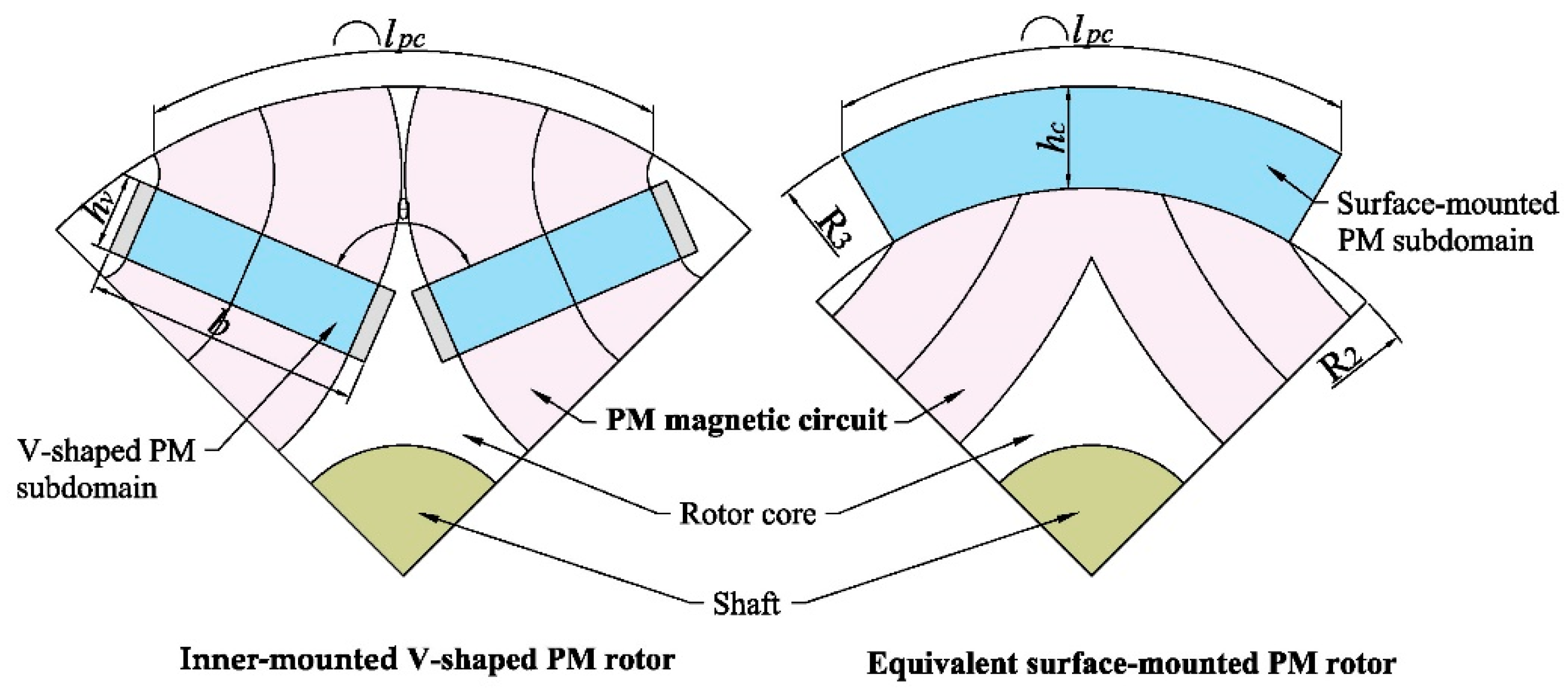
2. Analysis Model of the Magnetic Field of IPMSM

The studied magnetic field model of the motor is suitable for the IPMSM for new energy vehicles. The model does not consider the effect of large ferromagnetic loss, large eddy current loss and large temperature rise on the magnetic field. Therefore, to improve the accuracy of model application, the application of the model limits the rated speed of the motor to be less than 10,000 r/min, the rated power to be less than 100 kW, the temperature rise to be less than 100 °C and the highest insulation grade is grade B. Meanwhile, to simplify the calculation process, the model ignores the magnetic field at the end of the motor and equates the motor’s magnetic field to a 2D magnetic field model. Therefore, the model ignores the skin effect and axial length, considers that the axial distribution of magnetic field is uniform and limits the slenderness ratio of motor to less than 3.
For the analytical calculation of the subdomain model, it is essential to have standard boundary conditions in the 2D coordinate plane. To match the boundary of the Poisson equation, the V-shaped PM subdomain is equivalent to the fan-shaped surface-mounted PM subdomain. The equivalent model of the PM subdomain is shown in Figure 1.
The area and size of the equivalent fan-shaped surface-mounted PM subdomain should be determined by the V-shaped PM subdomain. To ensure the effectiveness of the equivalent size, the rotor surface magnetomotive force of the two PM subdomains should be equal. For the equivalent fan-shaped PM subdomain, the magnetomotive force on the rotor surface is the magnetomotive force generated by the fan-shaped PM minus the magnetomotive force of the leakage flux. Because the leakage flux is mainly distributed on both sides of the fan-shaped PM, both sides are the air subdomain, and the leakage flux is lesser and ignored. The equivalent rotor magnetomotive force A p c is calculated as follows [28]:
A p c = 0 l p c R 3 B p h c μ p d β
where l p c is the arc length of the fan-shaped PM subdomain; R 3 is the outer radius of the equivalent rotor; B p is the residual magnetic induction intensity of the PM material; h c is the thickness of the fan-shaped PM subdomain; μ p is the permeability of the PM material; and β is the included angle between the center of the magnetic pole and the connecting line between any point in the fan-shaped PM subdomain and the center of the rotor circle.
For the V-shaped PM subdomain, the rotor surface’s magnetomotive force is the magnetomotive force generated by the V-shaped PM minus the leakage flux magnetomotive force and the magnetomotive force consumed by the rotor core’s magnetic circuit. The leakage flux is mainly distributed at the end of rectangular PM, and it can be removed by shortening the calculation length. Meanwhile, to improve the accuracy of the model, the leakage flux coefficient of the motor is limited to less than 1.3. The magnetomotive force of the rotor core’s magnetic circuit can be calculated by the equivalent magnetic circuit method, which assumes that the magnetic circuit is linear and evenly distributed. In the calculation, the magnetic circuit of the rotor core is equivalent to a circular arc, which takes the intersection O of the inner extension line of the rectangular PM and the outer circle of the rotor as the center of the circle and the distance from the effective calculated length of the rectangular PM to the circle point as the radius. The calculation schematic diagram is shown in Figure 2.
As shown in Figure 2, both sides of the rectangular PM are the end magnetic leakage part, which is an invalid calculation area. The length of this part is recorded as b 1 , and the arc envelope area with the radius of the effective calculation part of the rectangular PM is the calculation area of the magnetic circuit of the rotor core. The included angles between the two ends of the effective calculated length of rectangular PM and the center line of rotor magnetic pole are recorded as β 1 and β 2 , respectively, which can be calculated as follows from the structural relationship:
{ β 1 = arctan l o sin θ 2 r p + l o cos θ 2 β 2 = arctan ( l o + b b 1 ) sin θ 2 r p + ( l o + b b 1 ) cos θ 2
where θ is the inclination angle of the inner side of two V-shaped rectangular PMs; l o is the distance from the intersection point of the inner side of V-shaped PM to its inner end of effective calculated length; r p is the distance from the intersection point of the inner side of V-shaped PM to the center of rotor circle; and b is the length of rectangular PM.
In any angle β within the effective calculation angle of rectangular PM, the radius r o and angle ε corresponding to the magnetic circuit inside the rectangular PM are calculated as follows:
{ r o = r p sin β 0 sin ( θ 2 β 0 ) r p sin β sin ( θ 2 β ) ε = arcsin ( r p sin β 0 2 R 1 sin ( θ 2 β 0 ) r p sin β 2 R 1 sin ( θ 2 β ) )
where β 0 is the included angle between the center of the rotor magnetic pole and the connecting line from the center O of the rotor magnetic circuit to the center of the rotor circle. R is the outer diameter of the rotor, and R 1 is the distance from the top of the V-shaped PM to the center of the rotor.
The inner magnetic circuit length l c of the rectangular PM at any angle β within the effective calculation angle of rectangular PM is as follows:
l c = 2 π ( r p sin β 0 sin ( θ 2 β 0 ) r p sin β sin ( θ 2 β ) ) arcsin ( r p sin β 0 2 R 1 sin ( θ 2 β 0 ) r p sin β 2 R 1 sin ( θ 2 β ) )
By integrating the effective arc length of one rotor magnetic pole, the magnetomotive force A p v of the V-shaped PM magnetic field transferred to the rotor surface can be obtained as follows:
A p v = 2 β 2 β 1 B p h v μ p ( B r l c μ r ) d β
where B r is the radial components of the magnetic flux density; h v is the length in the magnetization direction of rectangular PM; μ r is the permeability of rotor core.
The corresponding relationship between the two PM subdomains can be solved by making the rotor surface’s magnetomotive force generated by the two subdomains equal. In order to ensure the magnetic field distribution, the arc length of the fan-shaped PM subdomain must be made equal to that of the rotor surface corresponding to the V-shaped PM subdomain. This arc length l p c can be calculated as:
l p c = 4 π R ( β 0 2 arcsin ( r p sin β 0 2 R sin ( θ 2 β 0 ) l o + b 2 b 1 2 R 1 ) )
According to the principle of equal magnetomotive force on the rotor surface, the thickness of the fan-shaped PM subdomain can be calculated as follows:
h c = 2 R 3 μ p β 2 β 1 B p h v μ p ( B r l c μ r ) d β B p l p c
According to the above formula, the V-shaped PM subdomain is equivalent to the fan-shaped PM subdomain (hereinafter referred to as the PM subdomain). The IPMSM can be divided into 4 subdomains: the stator slot subdomain (subdomain I), the stator slot notch subdomain (subdomain II), the air-gap subdomain (subdomain III), and the PM subdomain (subdomain IV). The equivalent diagram is shown in Figure 3.
To simplify the mathematical model, the following assumptions are made in the model calculation:
  • Ignore eddy current loss and hysteresis loss;
  • The magnetic permeability of the stator and rotor cores is infinite, and the influence of the magnetic resistance is ignored;
  • Ignore the end effect and the difference of axial magnetic field distribution; it is assumed that the axial magnetic field distribution is uniform;
  • The magnetic flux distribution in the 2-D plane is linear and the magnetic field distribution is uniform;
  • The boundaries of each subdomain are in the radial or tangential direction;
  • The current density in the coil in the stator slot is evenly distributed, and there is only one component in the z-axis direction;
  • The permeability of armature winding is constant;
  • The demagnetization curve of PM material is linear;
  • Ignore the effect of temperature rise on the magnetic field.

2.1. General Solution of Each Subdomain

According to the different excitation sources, each subdomain’s magnetic field control equations are different. The vector magnetic quantities of the stator slot (subdomain I) and the PM (subdomain IV) meet the Poisson equation, and the stator slot notch (subdomain II) and air-gap (subdomain III) meet the Laplace equation. The general solution equation of the subdomains I, II, III, and IV are as follows:
{ I : 2 A z I i r 2 + 1 r A z I i r + 1 r 2 2 A z I i α 2 = μ 0 J II : A z II i r 2 + 1 r A z II i r + 1 r 2 2 A z II i α 2 = 0 III : 2 A z III i r 2 + 1 r A z III i r + 1 r 2 2 A z III i α 2 = 0 IV : 2 A z IV i r 2 + 1 r A z IV i r + 1 r 2 2 A z IV i α 2 = μ 0 r ( M α M r α )
where A z I i , A z II i , A z III i , and A z IV i are the vector magnetic potential in z-axis direction of subdomains I, II, III, and IV, respectively; r is the radius from a point in the subdomain to the center of the stator circle; α is the circumferential angle; μ 0 is the permeability of vacuum; J is the current density; M α and M r are the magnetization’s radial and tangential components under one pair of magnetic poles.
The value ranges of subdomain parameters are as follows:
{ I : R 5 < r < R 6 , α i b sa / 2 < α < α i + b sa / 2   II : R 4 < r < R 5 , α i b oa / 2 < α < α i + b oa / 2 III : R 3 < r < R 4 , 0 < α < 2 π IV : R 2 < α < R 3 , 0 < α < 2 π
where R 5 is the radius of the bottom circle of the stator slot; R 6 is the radius of the top circle of the stator slot; R 4 is the radius of the top circle of the stator slot notch; R 2 is the inner diameter of the equivalent outer rotor; α i is the i-th circumference; b sa is the stator slot width; and b oa is the stator slot notch width.
The boundary of the subdomain is related to the distribution and structure of the subdomain. The boundary conditions of each subdomain are as follows:
{ I : A z I i α | α = α i b sa 2 = 0 ,   A z I i α | α = α i + b sa 2 = 0 ,   A z I i r | r = R 6 = 0 II : A z II i α | α = α i b oa 2 = 0 ,   A z II i α | α = α i + b oa 2 = 0 III : { A z III i α | r = R 4 = { A z III i α | r = R 3 ,   α i b oa 2 < α < α i + b oa 2 0 ,   else A z III i α | r = R 3 = { 1 μ r A z III i α | r = R 2 ,   α i b sa 2 < α < α i + b sa 2 0 ,   else IV : A z IV i α | α = α i b oa 2 = 0 ,   A z IV i α | α = α i + b oa 2 = 0 ,   A z IV i r | r = R 2 = 0
According to the boundary conditions, the general solution of the vector magnetic potential of each subdomain can be obtained by solving the equations of each subdomain. The armature winding in the stator slot subdomain adopts the centralized winding, the current density in the slot is distributed on the left and right, and its current density is symmetrical. Therefore, the left and right boundaries of the slot are mirrored, and it becomes a periodic signal with a period of 2 α i . The current density distribution in the stator slot in one cycle after mirroring is shown in Figure 4.
According to Figure 4, the Fourier function of the current density J in the stator slot in one cycle is calculated as:
J = n 2 n π ( J i 1 + J i 2 ) sin ( n π / 2 ) cos [ n π b sa ( α + b sa / 2 α i ) ] + J i 1 + J i 2 2
where n is the spatial harmonic logarithm in the stator slot subdomain; J i 1 . and J i 2 . are the current density of the two sets of windings in the stator slot.
The general solution can be solved by the variable separation method [29,30,31]. The general solution of the vector magnetic potential of the stator slot subdomain is expressed as follows:
A z I i = [ μ 0 r 2 ln r ( J i 1 + J i 2 ) ] 8 + n { [ A I ( R 5 R 6 ) ( r R 6 ) n + B I ( r R 5 ) n ] cos [ n π ( 2 α 2 α i + b sa ) 2 b sa ] + 2 μ 0 ( J i 1 + J i 2 ) sin ( n π / 2 ) n π [ ( n π / b sa ) 2 4 ] [ r 2 2 E n R 6 2 ( r R 6 ) n ] cos [ ( n π b sa ) ( α + b sa 2 α i ) ] }
where A I and B I are the harmonic coefficients of the stator slot subdomain; E n is n-the back electromotive force (EMF).
The general solution of the vector magnetic potential of the stator slot notch subdomain can be calculated as follows:
A z II i = m { [ A II ( r R 5 ) m + B II ( r R 4 ) m ] cos [ m ( α + b oa 2 α i ) ] + [ C II ( r R 5 ) m D II ( r R 4 ) m ] sin [ m ( α + b oa 2 α i ) ] }
where A II , B II , C II , and D II are the harmonic coefficients of the stator slot subdomain; m is the spatial harmonic logarithm in the stator slot notch subdomain; and m is the spatial harmonic logarithm in the stator slot notch subdomain.
The general solution of vector magnetic potential of the air-gap subdomain (subdomain III) can be calculated as follows:
A z III i = k [ A III ( r R 4 ) k + B III ( r R 3 ) k ] cos ( k α ) + k [ C III ( r R 4 ) k + D III ( r R 3 ) k ] sin ( k α )
where A III , B III , C III , and D III are the harmonic coefficients of the air-gap subdomain; k is the spatial harmonic logarithm in the air-gap subdomain.
In the PM subdomain, the equivalent fan-shaped surface-mounted PM adopts radial magnetization, and the magnetization method is shown in Figure 5.
Under a pair of magnetic poles, the radial and tangential components of PM magnetization can be decomposed by Fourier series, which are calculated as follows:
{ M r = n = 1 , 3 , 5 B p α p μ 0 sin α IV 1 α IV 1 cos [ l ( α + l p c 2 R 3 α i ) ] M α = n = 1 , 3 , 5 B p α p μ 0 sin α IV 2 α IV 2 sin [ l ( α + l p c 2 R 3 α i ) ]
where l is the spatial harmonic logarithm in the PM subdomain; α p is polar arc coefficient, and α p = l p c 2 R 3 / π 2 p = p l p c π R 3 , where p is the number of motor pole pairs; α IV 1 is left circumferential angle of PM field, and α IV 1 = ( l + 1 ) α p / 2 p ; α IV 2 is the right circumferential angle of PM field, and α IV 2 = ( l 1 ) α p / 2 p .
The general solution of vector magnetic potential of the PM subdomain is expressed as follows:
A z IV i = A IV + B IV ln r + l [ C IV ( r R 3 ) l + D IV ( r R 2 ) l ] cos ( α + p l p c π R 3 α i ) + l μ 0 ( M rl M α l 2 ln r ) cos ( l π b oa ) ( α + p l p c π R 3 α i )
where A IV , B IV , C IV , and D IV are the harmonic coefficients of the PM subdomain.

2.2. Calculation of Undetermined Coefficients of Each Subdomain

Since the normal magnetic flux density and tangential magnetic field strength at the interface of adjacent subdomains are equal, the harmonic coefficients in the vector magnetic potential of each subdomain can be solved as follows:
{ A z I i | r = R 5 A z II i | r = R 5 = 0 , α i b oa 2 α α i b oa 2 H z I | r = R 5 H z II | r = R 5 = 0 , α i b oa 2 α α i b oa 2 A z II i | r = R 4 A z III i | r = R 4 = 0 , α i b oa 2 α α i b oa 2 H z II | r = R 4 H z III | r = R 4 = 0 , α i b oa 2 α α i b oa 2 A z III i | r = R 3 A z IV i | r = R 3 = 0 , α i p l p c π R 3 α α i + p l p c π R 3 H z II | r = R 3 H z IV | r = R 3 = 0 , α i p l p c π R 3 α α i + p l p c π R 3
where H z I i , H z II i , H z III i , and H z IV i are the tangential vectors of magnetic field intensity of the four subdomains.

2.3. Analytical Model of the Magnetic Field in Each Subdomain

According to the relationship between the magnetic flux density and the vector magnetic potential, the radial and tangential components of the magnetic flux density can be expressed as follows [32,33]:
B r = 1 r A α
B α = A r
where A is the vector magnetic potential of subdomain; B r is the radial components of the magnetic flux density; B α is the tangential components of the magnetic flux density.
The expression of the magnetic flux density of each subdomain is solved according to the general solution of the vector magnetic potential of each subdomain. The magnetic flux density’s radial and tangential components in the stator slot subdomain can be calculated as:
B z I r = E n n { [ A I ( R 5 R 6 ) ( r R 6 ) n + B I ( r R 5 ) n ] sin [ ( n π b sa ) ( α + b sa 2 α i ) ] { 2 μ 0 ( J i 1 + J i 2 ) sin ( n π / 2 ) [ r 2 2 E n R 6 2 ( r R 6 ) n ] [ r 2 2 E n R 6 2 ( r R 6 ) n ] sin [ ( n π b sa ) ( α + b sa 2 α i ) ] } b sa r [ ( n π / b sa ) 2 4 ] }
B z I α = n { n [ A I ( R 5 R 6 ) ( r R 6 ) n 1 + B I ( r R 5 ) n 1 ] cos [ E n ( α + b sa 2 α i ) ] { 2 μ 0 ( J i 1 + J i 2 ) sin ( n π / 2 ) [ 2 r 2 E n n R 6 2 ( r R 6 ) n 1 ] cos [ ( n π b sa ) ( α + b sa 2 α i ) ] } n π [ ( n π / b sa ) 2 4 ] }
where B z I r is the radial components of the magnetic flux density in the stator slot subdomain; B z I α is the tangential components of the magnetic flux density in the stator slot subdomain.
The magnetic flux density’s radial and tangential components in the stator slot notch subdomain can be calculated as follows:
B z II r = m r m { [ A II ( r R 5 ) m + B II ( r R 4 ) m ] sin [ m ( α + b oa 2 α i ) ] m r [ C II ( r R 5 ) m D II ( r R 4 ) m ] cos [ m ( α + b oa 2 α i ) ] }
B z II α = m { m [ A II ( r R 5 ) m 1 B II ( r R 4 ) m 1 ] cos [ m ( α + b oa 2 α i ) ] m [ C II ( r R 5 ) m 1 + D II ( r R 4 ) m 1 ] sin [ m ( α + b oa 2 α i ) ] }
where B z II r is the radial components of the magnetic flux density in the stator slot notch subdomain; B z II α is the tangential components of the magnetic flux density in the stator slot notch subdomain.
The magnetic flux density’s radial and tangential components in the air-gap subdomain can be calculated as follows:
B z III r = k r k [ A III ( r R 4 ) k + B III ( r R 3 ) k ] sin ( k α ) + k r k [ C III ( r R 4 ) k + D III ( r R 3 ) k ] cos ( k α )
B z III α = k [ k A III ( r R 4 ) k 1 k B III ( r R 3 ) k 1 ] cos ( k α ) k [ k C III ( r R 4 ) k 1 k D III ( r R 3 ) k 1 ] sin ( k α )
where B z III r is the radial components of the magnetic flux density in the air-gap subdomain; B z III α is the tangential components of the magnetic flux density in the air-gap subdomain.
To obtain higher output quality, PM motors used in new energy vehicles mostly use a non-uniform air gap, which can effectively optimize the magnetic flux density distribution, reduce the distortion rate of back EMF waveform and the cogging torque of the motor. Therefore, the structure of the non-uniform air-gap PM motor is obtained by the method of rotor eccentricity, and the cogging torque and back EMF of uniform air gap and non-uniform air gap PM motor are calculated based on the analytical model. The structure diagram of the non-uniform air gap is shown in Figure 6.
According to the geometric relationship shown in Figure 6, the outer radius of the non-uniform air-gap rotor is as follows:
R 3 = R 3 + R 3 2 + h 2 2 R 3 h cos ( π χ )
where R 3 is the radius of the eccentric circle, h is rotor eccentricity, χ is the included angle between the radius of any eccentric circle and the center of the circle, and 0 χ θ 2 .
The variation in the eccentric rotor radius is recorded as Δ R 3 , and Δ R 3 = R 3 2 + h 2 2 R 3 h cos ( π χ ) . Based on this, Equation (32) is simplified as follows:
R 3 = R 3 + Δ R 3
Substituting (27) into (24) and (25), respectively, the radial and tangential components of the air-gap magnetic flux density of the non-uniform air-gap motor can be obtained as follows:
B z III r = k r k [ A III ( r R 4 ) k + B III ( r R 3 + Δ R 3 ) k ] sin ( k α ) + k r k [ C III ( r R 4 ) k + D III ( r R 3 + Δ R 3 ) k ] cos ( k α )
B z III α = k [ k A III ( r R 4 ) k 1 k B III ( r R 3 + Δ R 3 ) k 1 ] cos ( k α ) k [ k C III ( r R 4 ) k 1 k D III ( r R 3 + Δ R 3 ) k 1 ] sin ( k α )
The magnetic flux density’s radial and tangential components in the PM subdomain can be calculated as follows:
B z IV r = 1 r l [ C IV ( r R 3 ) l + D IV ( r R 2 ) l ] sin ( α + p l p c π R 3 α i ) 1 r l π b oa l μ 0 ( M r l M α l 2 ln r ) sin ( l π b oa ) ( α + p l p c π R 3 α i )
B z IV α = l [ l C IV ( r R 3 ) l 1 l D IV ( r R 2 ) l 1 ] cos ( α + p l p c π R 3 α i ) l μ 0 ( M r l M α l 2 r ) cos ( l π b oa ) ( α + p l p c π R 3 α i ) B IV r
where B z IV r is the radial components of the magnetic flux density in the PM subdomain; B z IV α is the tangential components of the magnetic flux density in the PM subdomain.
In order to further verify the calculation accuracy of the improved subdomain method, the output characteristics such as back EMF and cogging torque of the motor calculate are calculated, which can explore the influence of the deviation degree generated in calculating the air gap flux density on the output characteristics of the motor. For the double winding, the magnetic linkage of the left and right coils can be obtained from the vector magnetic potential of the air-gap subdomain, which can be calculated as follows:
ψ i 1 = L a N c A c R 3 R 4 α i b oa 2 α i A z III i r d r d α
ψ i 2 = L a N c A c R 3 R 4 α i α i + b oa 2 A z III i r d r d α
Where ψ i 1 and ψ i 2 are the magnetic linkage of the left and right coils, respectively; L a is the axial length of the core; N c is the turns of armature winding; A c is the armature winding surface area.
Substituting (14) into (32) and (33), respectively, the magnetic linkage of the left and right coils under a uniform air gap can be obtained:
ψ i 1 = L a N c A c { sin ( k α i ) sin [ k ( α i b oa / 2 ) ] k [ A III k R 4 k + 2 R 3 k + 2 ( k + 2 ) R 4 k + B III k ( R 4 2 k R 3 2 k ) R 3 k 2 k ] + cos [ k ( α i b oa / 2 ) ] cos ( k α i ) k [ C III k R 4 k + 2 R 3 k + 2 ( k + 2 ) R 4 k + D III k ( R 4 2 k R 3 2 k ) R 3 k 2 k ] }
ψ i 2 = L a N c A c { sin k ( α i + b oa / 2 ) sin k α i k [ A III k R 4 k + 2 R 3 k + 2 ( k + 2 ) R 4 k + B III k ( R 4 2 k R 3 2 k ) R 3 k 2 k ] + cos [ k ( α i + b oa / 2 ) ] cos ( k α i ) k [ C III k R 4 k + 2 R 3 k + 2 ( k + 2 ) R 4 k + D III k ( R 4 2 k R 3 2 k ) R 3 k 2 k ] }
In the same way, substituting (27) into (34) and (35) can obtain the magnetic linkage of the left and right coils under the non-uniform air gap. Moreover, the total magnetic linkage ψ i in one stator slot can be calculated as the sum of the magnetic linkage of the left and right coils in the slot, that is, ψ i = ψ i 1 + ψ i 2 .
The three-phase magnetic linkage can be calculated as follows:
[ φ A φ B φ C ] = 1 a C [ ψ 1 , ψ 2 , ψ 3 , ψ 2 Q s ] T
where φ A , φ B , and φ C are the magnetic linkage of phase A, phase B, and phase C, respectively; a is the number of parallel branches; C is the calculation constant of magnetic linkage; ψ 1 , ψ 2 , ψ 3 , and ψ 2 Q s are the magnetic linkages in different slots; and Q s is the number of stator slots.
The back EMF of the motor is induced by the time-varying magnetic linkage. The expression of the back EMF of phase A E A can be calculated as follows:
E A = d φ A d t
The cogging torque T cog of the motor can be calculated as follows:
T cog = κ [ 1 2 μ 0 B z III 2 d V ]
where κ is the angle between the centerline of a specified PM and the centerline of a specified stator tooth; B z III is the magnetic flux density in the PM subdomain.
Substituting (28) and (29) into (38) can obtain the cogging torque expression of the non-uniform air gap. Using the magnetic flux density calculation equation of the above subdomain, the magnetic field distribution of the motor can be calculated and analyzed.

3. Verification and Analysis of the Model

To verify the accuracy of the analytical model, the finite element model of the IPMSM is established by finite element software, and the magnetic flux density cloud diagram, and the magnetic flux distribution of the motor are simulated and shown in Figure 7. The main technical parameters of the motor are shown in Table 1.
Figure 7 shows that the magnetic field direction of the IPMSM is correct, and the linkage flux of the designed PM motor is mainly distributed at the left and right ends of the PM. Moreover, when the total magnetic flux of each pole is 16, there are only three leakage fluxes. This shows that compared with the conventional IPMSM (such as tangential PM motor, radial PM motor, etc.), the linkage flux is less. In addition, the magnetic field distribution of the rotor core and the stator core is uniform. The saturated magnetic field is mainly distributed at the end of the PMs, which can effectively reduce the magnetic leakage and improve the main magnetic flux. Meanwhile, there is a small amount of saturation at the stator yoke, the utilization rate of the stator core is high, and the magnetic field distribution is reasonable. There is a small amount of saturation at the end of PM and stator yoke, which can improve the utilization rate of the stator core. The comparison diagrams of the magnetic flux density at the middle position of the air gap are shown in Figure 8.
As shown in Figure 8, the analytical method based on the accurate subdomain model is quite consistent with the calculation results of the finite element method. The fundamental amplitude error rate is only 3.3%, which shows that the analytical model has high accuracy. This is because the theoretical basis of the analytical calculation method is the Laplace equation and Poisson equation, and the highest order of Fourier series expansion should be infinity. However, in the practical calculation, the highest order can only be set to an appropriate finite value. Otherwise, the dimension of matrix equations will be too large to be solved. Using the subdomain model, the magnetic flux density of the main air gap in the uniform air gap and non-uniform air gap can be solved, as shown in Figure 9.
Figure 9 shows that when the rotor eccentricity is 4 mm, the amplitude of the air-gap magnetic flux density waveform is basically the same. However, the peak value of the magnetic flux density of the non-uniform air gap has a small depression, and the waveform is smoother. This shows that the non-uniform air gap can effectively reduce the content of higher harmonics of magnetic flux density, so as to improve the motor’s output quality.
When the PM rotor is in the no-load operation condition, the back EMF and cogging torque of the motor with uniform air gap and non-uniform air gap are calculated, as shown in Figure 10 and Figure 11, respectively.
Figure 10 shows that the back EMF amplitude under different air gaps is basically the same. However, the waveform of the non-uniform air gap is closer to the sine wave, with less fluctuation and a smoother curve. It also proves that the magnetic flux density of the non-uniform air gap has less high-order harmonic content, which is consistent with the previous conclusion. Figure 11 shows that when the motor has a uniform air gap, the cogging torque of the motor fluctuates greatly, and the peak value of cogging torque is 526.3 mN × m. When the motor has a non-uniform air gap, the cogging torque fluctuation of the motor is small, and the peak value of the cogging torque is 316.2 mN × m, which is 41.8% lower than that of the uniform air-gap rotor. This shows that the non-uniform air gap can effectively weaken the higher harmonics in the air-gap magnetic flux density and reduce the cogging torque.
The finite element model of the motor is established and simulated to obtain the cogging torque under no-load condition. The comparison with the calculation results is shown in Figure 12.
It can be seen from Figure 12 that the cogging torque curve calculated by the subdomain model is almost the same as the simulation result, and the peak value of the calculation result is slightly less than the simulation result. The peak values of calculation results and simulation results are 199.442 mN × m and 205.027 mN × m, respectively, and their peak error is 2.8%. The maximum error of the two results is also the peak error. The root mean square of relative error and correlation coefficient between the simulation results and calculation results are 0.01 and 0.999995, respectively. The deviation between the simulation results and the calculation results is small, which can prove the effectiveness of the calculation model.
To further verify the accuracy of the analysis model, the IPMSM is trial manufactured and tested. The prototype adopts a non-uniform air gap, as shown in Figure 13. The motor test bench is shown in Figure 14.
The no-load operation test of the motor is carried out on the motor test bench, and the back EMF of the motor is obtained, which is smoothed to obtain the optimized curve. The comparison between the two curves and the comparison between the optimized test results, the calculation results, and simulation results are shown in Figure 15.
Figure 15 shows that the trend of the motor back EMF curve of the optimized test results is almost the same as that of the real test results, and they have a good fit. The motor back EMF waveform obtained from the test is basically the same as the calculation results and simulation results. The output waveform of the motor has good sinusoidality. In order to analyze the deviation of the three methods, based on the calculation results, the peak value, peak error, maximum deviation, root mean square of relative error, and correlation coefficient of the motor back EMF curve obtained by each method are calculated, and the results are shown in Table 2.
Table 2 shows that the peak value of the calculation results is 35.166 V. Based on the calculation results, the peak errors of the motor back EMF obtained by the simulation method and the test method are 2.343% and 4.393%, respectively, and the maximum errors of the back EMF curve are 2.345% and 6.887%, respectively. The error of the simulation results is smaller than test results. However, the root mean square of relative error and correlation coefficient of the test method are 0.108 and 0.999736, respectively, which shows that the overall error between the back EMF obtained by the test and the calculation results is small, and the calculation results is effective.
Adjusting the input voltage of the motor controller to the rated voltage, the mechanical characteristic curves of the PM motor can be obtained by the dynamometer test, as shown in Figure 16.
Figure 16 shows that under the rated load condition, the PM motor can maintain stable output torque and speed, and the high-efficiency working range (Efficiency 80%) accounts for more than 88% of the total working range. The designed motor has good output characteristics.

4. Conclusions

The paper proposes an analytical calculation method of the magnetic field of the IPMSM used in the new energy vehicles. Using Kirchhoff’s law, the V-shaped PM subdomain is equivalent to the surface-mounted fan-shaped PM subdomain, and the parameter calculation formula of the equivalent subdomain is given. The analytical models of the magnetic flux density of the stator slot subdomain, the stator slot notch subdomain, the air-gap subdomain, and the PM subdomain are established, and the effectiveness of the analytical model is verified by the finite element method. Based on the analytical model of magnetic flux density, the non-uniform air-gap model is analyzed and verified by the finite element method. The results show that the non-uniform air-gap structure can effectively reduce the higher harmonic content in the air-gap magnetic flux density, improve the waveform of back EMF, and reduce the cogging torque of the motor. The prototype is trial manufactured and the no-load characteristic test and mechanical characteristics are carried out. The results show that the peak error and the root mean square of relative error between the test results and the calculation results of the back EMF are 4.393% and 0.108, respectively. The high efficiency working range of the motor (efficiency 80%) accounts for more than 88% of the total working range. Therefore, the proposed analytical model is accurate. Using this model, the magnetic field distribution and electromagnetic characteristic parameters of IPMSM can be effectively analyzed to complete the verification and optimization of motor design.

Author Contributions

Conceptualization, H.G., Y.Z. and X.Z.; validation, H.G., X.Z. and S.Y.; investigation, L.W., Y.H. and W.W.; resources, H.G. and Y.Z.; data curation, H.G., S.Y. and Y.Z.; writing—original draft preparation, H.G. and Y.Z.; writing—review and editing, H.G. and X.Z.; visualization, L.W. and W.W.; supervision, X.Z., L.W. and Y.H.; project administration, X.Z.; funding acquisition, X.Z. All authors have read and agreed to the published version of the manuscript.

Funding

This research was funded by the National Natural Science Foundation of China, grant numbers (51875327 and 51975340).

Institutional Review Board Statement

Not applicable.

Informed Consent Statement

Not applicable.

Data Availability Statement

The data presented in this study are available on request from the corresponding author. The data are not publicly available because they are part of ongoing research.

Conflicts of Interest

The authors declare no conflict of interest.

Nomenclature

A p c Equivalent rotor magnetomotive force of PM subdomain
l p c Arc length of fan-shaped PM subdomain
R 3 Outer radius of the equivalent rotor
B p Residual magnetic induction intensity of PM material
h c Thickness of fan-shaped PM subdomain
μ p Permeability of PM material
β 
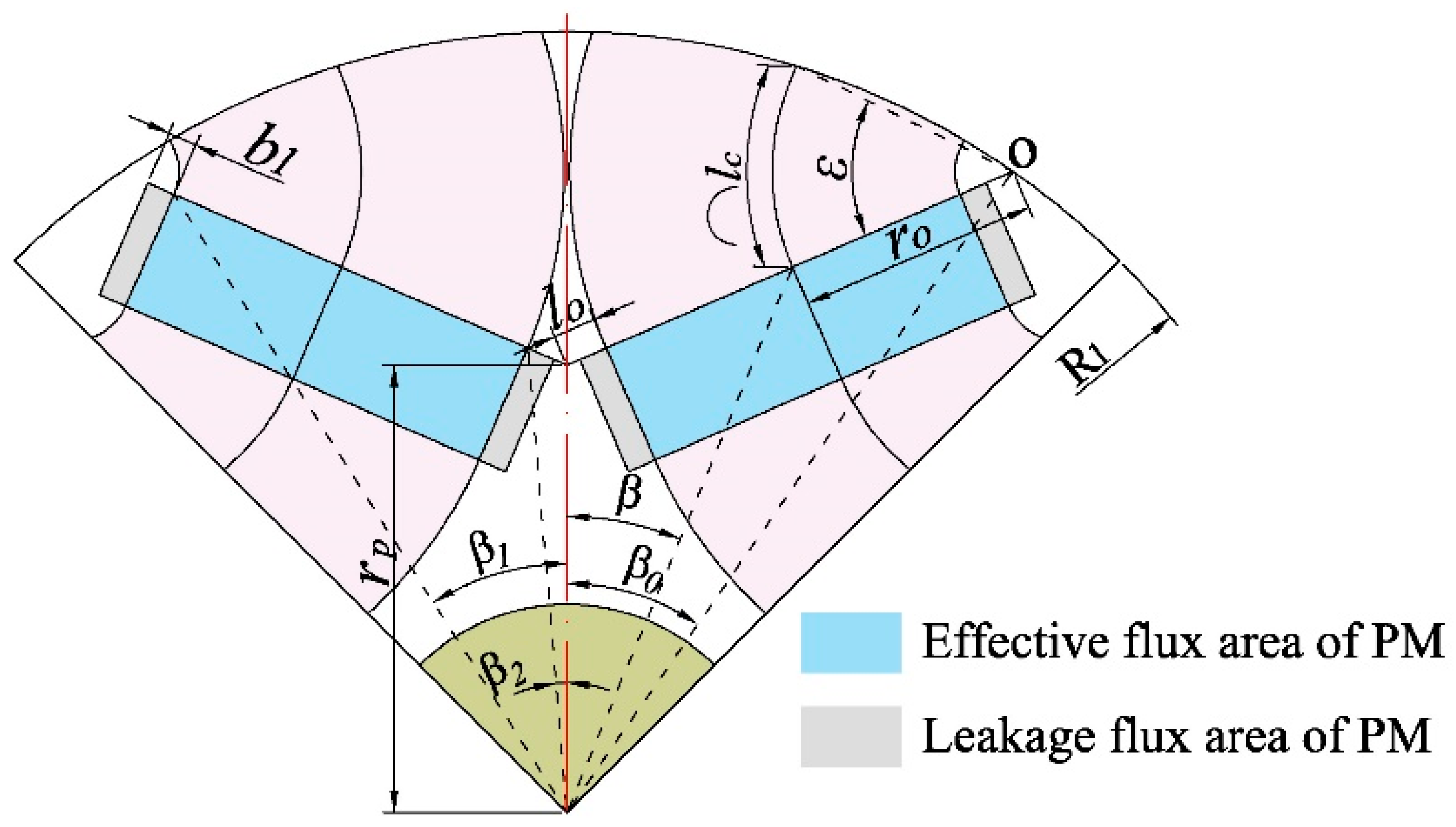
Included angle between the center of the magnetic pole and the connecting line between any point in the effective PM subdomain and the rotor circle’s center
O Intersection of the inner extension line of the rectangular PM and the outer circle of the rotor as the center of the circle
β 1 Included angle between the outer end of the effective calculated length of rectangular PM and the center line of the rotor magnetic pole
β 2 Included angle between the inner end of the effective calculated length of rectangular PM and the center line of rotor magnetic pole
θ Inclination angle of the inner side of two V-shaped rectangular PMs
l o The distance from the intersection point of the inner side of V-shaped PM to its inner end of effective calculated length
r p The distance from the intersection point of the inner side of V-shaped PM to the center of rotor circle
b Length of rectangular PM
b 1 The distance of the PM length occupied by the leakage flux at one end of the rectangular PM
r o Radius corresponding to the magnetic circuit inside the rectangular PM
ε Angle corresponding to the magnetic circuit inside the rectangular PM
β 0 Included angle between the center of the rotor magnetic pole and the connecting line from the center O to the center of the rotor circle
R Outer diameter of the rotor
R 1 Distance from the top of the V-shaped PM to the center of the rotor
l c Inner magnetic circuit length of rectangular PM at any angle within the effective calculation angle
A p v Rotor magnetomotive force of V-shaped PM subdomain
B r c Magnetic flux density of rotor core
h v Length in the magnetization direction of rectangular PM
μ r Permeability of rotor core
A z i Vector magnetic potential in z-axis direction of stator slot subdomain
A z II i Vector magnetic potential in z-axis direction of stator slot notch subdomain
A z III i Vector magnetic potential in z-axis direction of air-gap subdomain
A z IV i Vector magnetic potential in z-axis direction of PM subdomain
r Radius from a point in the subdomain to the center of the stator circle
α Circumferential angle
μ 0 Permeability of vacuum
J Current density
M α 
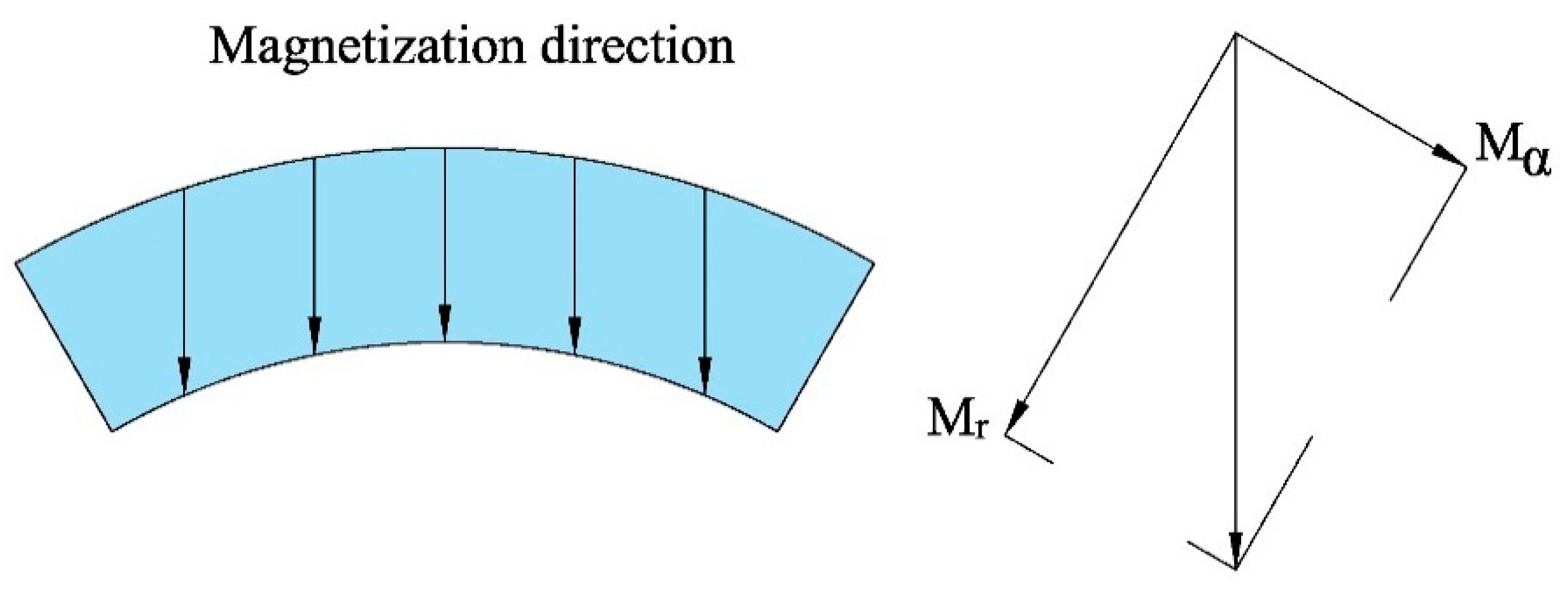
Magnetization’s radial components under one pair of magnetic poles
M r Magnetization’s tangential components under one pair of magnetic poles
R 5 Radius of the bottom circle of the stator slot
R 6 Radius of the top circle of the stator slot
R 4 Radius of the top circle of the stator slot notch
R 2 Inner diameter of equivalent rotor outer
α i i-th circumference
b sa Stator slot width
b oa Stator slot notch width
nSpatial harmonic logarithm in the stator slot subdomain
J i 1 Current density of left winding in slot
J i 2 Current density of right winding in slot
A I Harmonic coefficients of the stator slot subdomain
B I Harmonic coefficients of the stator slot subdomain
E n n-th back EMF
A II Harmonic coefficients of the stator slot subdomain
B II Harmonic coefficients of the stator slot subdomain
C II Harmonic coefficients of the stator slot subdomain
D II Harmonic coefficients of the stator slot subdomain
mSpatial harmonic logarithm in the stator slot notch subdomain
A III Harmonic coefficients of the air-gap subdomain
B III Harmonic coefficients of the air-gap subdomain
C III Harmonic coefficients of the air-gap subdomain
D III Harmonic coefficients of the air-gap subdomain
kSpatial harmonic logarithm in the air-gap subdomain
lSpatial harmonic logarithm in the PM subdomain
α p Polar arc coefficient
pNumber of motor pole pairs
α IV 1 Left circumferential angle of PM field
α IV 2 Right circumferential angle of PM field
A IV Harmonic coefficients of the PM subdomain
B IV Harmonic coefficients of the PM subdomain
C IV Harmonic coefficients of the PM subdomain
D IV Harmonic coefficients of the PM subdomain
H z I i Tangential magnetic field intensity vectors of stator slot notch subdomain
H z II i Tangential magnetic field intensity vectors of stator slot subdomain
H z III i Tangential magnetic field intensity vectors of air-gap subdomain
H z IV i Tangential magnetic field intensity vectors of PM subdomain
A Vector magnetic potential of subdomain
B r Radial components of the magnetic flux density
B α Tangential components of the magnetic flux density
B z I r Radial components of the magnetic flux density in the stator slot notch subdomain
B z I α Tangential components of the magnetic flux density in the stator slot notch subdomain
B z II r Radial components of the magnetic flux density in the stator slot subdomain
B z II α Tangential components of the magnetic flux density in the stator slot subdomain
B z III r Radial components of the magnetic flux density in the air-gap subdomain
B z III α Tangential components of the magnetic flux density in the air-gap subdomain
R 3 
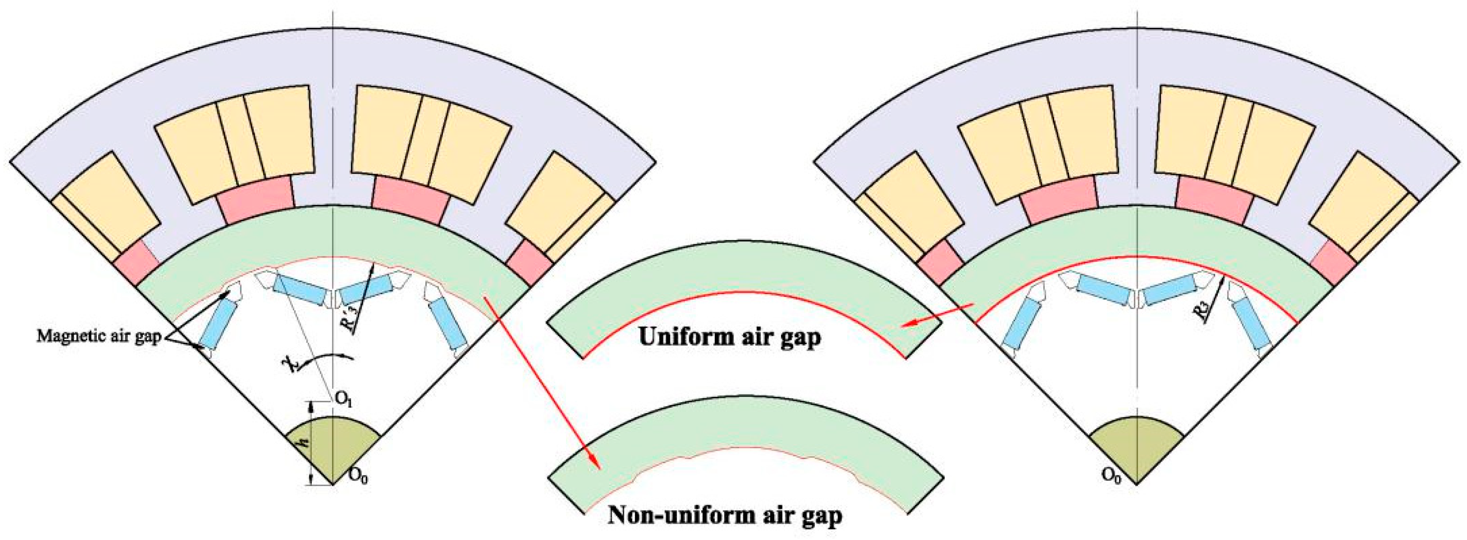
Radius of the eccentric circle
h Rotor eccentricity
χ Included angle between the radius of any eccentric circle and the center of the circle
Δ R 3 Variation of eccentric rotor radius
B z IV r Radial components of the magnetic flux density in the PM subdomain
B z IV α Tangential components of the magnetic flux density in the PM subdomain
ψ i 1 Magnetic linkage of the left coils
ψ i 2 Magnetic linkage of the right coils
L a Axial length of the core
N c Turns of armature winding
A c Armature winding surface area
ψ i Total magnetic linkage in one stator slot
φ A Magnetic linkage of phase A
φ B Magnetic linkage of phase B
φ C Magnetic linkage of phase C
a Number of parallel branches
C Calculation constant of magnetic linkage
ψ 1 Magnetic linkage in slot 1
ψ 2 Magnetic linkage in slot 2
ψ 3 Magnetic linkage in slot 2
ψ 2 Q s Magnetic linkage in slot 2 Q s
Q s Number of stator slots
E A Back EMF of phase A
T cog 
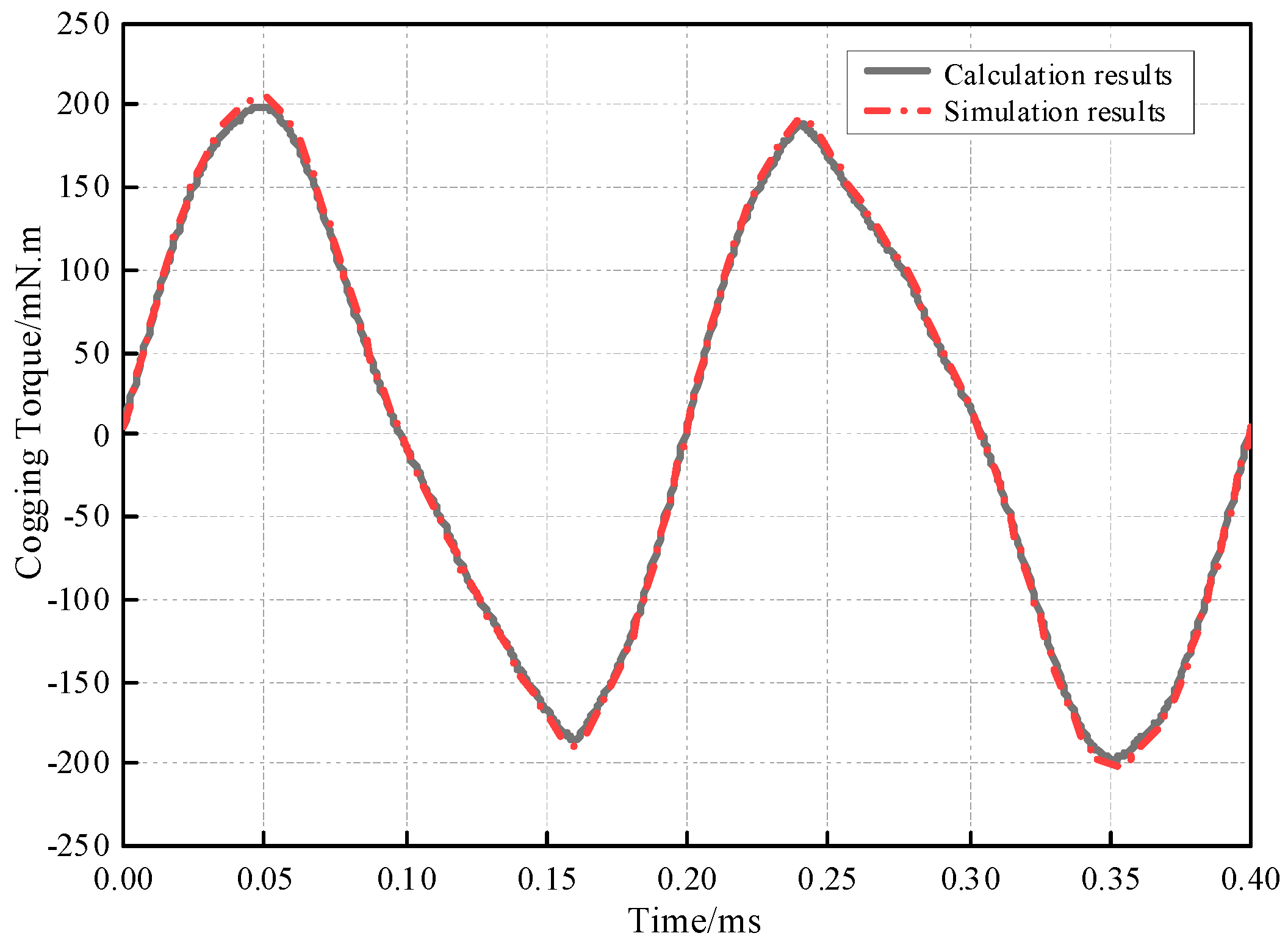
Cogging torque of the motor
κ Angle between the centerline of a specified PM and the centerline of a specified stator tooth

References

  1. Ullah, K.; Guzinski, J.; Mirza, A.F. Critical Review on Robust Speed Control Techniques for Permanent Magnet Synchronous Motor (PMSM) Speed Regulation. Energies 2022, 15, 1235. [Google Scholar] [CrossRef]
  2. Zhang, Y.; Zhao, C.; Dai, B.; Li, Z. Dynamic Simulation of Permanent Magnet Synchronous Motor (PMSM) Electric Vehicle Based on Simulink. Energies 2022, 15, 1134. [Google Scholar] [CrossRef]
  3. Tanaka, C.N.; Chabu, I.E. Flux Reversal Free Splittable Stator Core Doubly Salient Permanent Magnet Motor. IEEE Lat. Am. Trans. 2020, 18, 1329–1336. [Google Scholar] [CrossRef]
  4. Zhou, R.; Li, G.; Wang, Q.; He, J. Torque Calculation of Permanent-Magnet Spherical Motor Based on Permanent-Magnet Surface Current and Lorentz Force. IEEE Trans. Magn. 2020, 56, 1–9. [Google Scholar] [CrossRef]
  5. Iwama, K.; Noguchi, T. Operation Characteristics of Adjustable Field IPMSM Utilizing Magnetic Saturation. Energies 2022, 15, 52. [Google Scholar] [CrossRef]
  6. Liu, M.; Zou, J.; Xu, Y.; Lan, H.; Yu, G. Vibration Enhancement or Weakening Effect Caused by Permanent Magnet Synchronous Motor Radial and Tangential Force Formed by Tooth Harmonics. Energies 2022, 15, 744. [Google Scholar] [CrossRef]
  7. Zhang, X.; Du, Q.; Xu, J.; Zhao, Y.; Ma, S. Development and Analysis of the Magnetic Circuit on Double-Radial Permanent Magnet and Salient-Pole Electromagnetic Hybrid Excitation Generator for Vehicles. Chin. J. Mech. Eng. 2019, 32, 100–112. [Google Scholar] [CrossRef] [Green Version]
  8. Song, I.-S.; Jo, B.-W.; Kim, K.-C. Analysis of an IPMSM Hybrid Magnetic Equivalent Circuit. Energies 2021, 14, 5011. [Google Scholar] [CrossRef]
  9. Zhao, W.; Yang, Z.; Liu, Y.; Wan, X.g. Analysis of a Novel Surface-Mounted Permanent Magnet Motor with Hybrid Magnets for Low Cost and Low Torque Pulsation. IEEE Trans. Magn. 2021, 57, 1–4. [Google Scholar] [CrossRef]
  10. Tan, Q.; Wang, M.; Li, L. Analysis of a New Flux Switching Permanent Magnet Linear Motor. IEEE Trans. Magn. 2021, 57, 1–5. [Google Scholar] [CrossRef]
  11. Geng, H.; Zhang, X.; Tong, L.; Ma, Q.; Xu, M.; Zhang, Y.; Wang, L. Performance Optimization Analysis of Hybrid Excitation Generator with the Electromagnetic Rotor and Embedded Permanent Magnet Rotor for Vehicle. IEEE Access 2021, 9, 163640–163653. [Google Scholar] [CrossRef]
  12. Jeong, W.-S.; Lee, Y.-S.; Lee, J.-H.; Lee, C.-H.; Won, C.-Y. Space Vector Modulation (SVM)-Based Common-Mode Current (CMC) Reduction Method of H8 Inverter for Permanent Magnet Synchronous Motor (PMSM) Drives. Energies 2022, 15, 266. [Google Scholar] [CrossRef]
  13. Hayslett, S.; Strangas, E. Analytical Design of Sculpted Rotor Interior Permanent Magnet Machines. Energies 2021, 14, 5109. [Google Scholar] [CrossRef]
  14. Geng, H.; Zhang, X.; Si, T.; Tong, L.; Ma, Q.; Xu, M. Analysis of the Rotor Magnetomotive Force of Built-In Radial Permanent Magnet Generator for Vehicle. Int. J. Rotating Mach. 2021, 2021, 5319615. [Google Scholar] [CrossRef]
  15. Hu, W.; Zhang, X.; Yin, H.; Geng, H.; Zhang, Y.; Shi, L. Analysis of Magnetic Field and Electromagnetic Performance of a New Hybrid Excitation Synchronous Motor with dual-V type Magnets. Energies 2020, 13, 1501. [Google Scholar] [CrossRef] [Green Version]
  16. Geng, H.; Zhang, X.; Zhang, Y.; Hu, W.; Lei, Y.; Xu, X.; Wang, A.; Wang, S.; Shi, L. Development of Brushless Claw Pole Electrical Excitation and Combined Permanent Magnet Hybrid Excitation Generator for Vehicles. Energies 2020, 13, 4723. [Google Scholar] [CrossRef]
  17. Zhang, H.; Deng, Z.; Yang, J.; Tuo, J.; Zhang, Y. Analytical Calculation and Analysis of Magnetic Field in Surface-mounted Permanent Magnet Motor. Automot. Eng. 2018, 40, 850–857. (In Chinese) [Google Scholar]
  18. Guo, S.; Zhou, L. Analytical Solution of Magnetic Field in Surface-Inset Permanent Magnet Machines. Proc. CSEE 2015, 35, 710–718. (In Chinese) [Google Scholar]
  19. Oner, Y.; Zhu, Z.Q.; Wu, L.; Xiao, G.; Chen, J. Analytical on-load subdomain field model of permanent-magnet vernier machines. IEEE Trans. Ind. Electron. 2016, 63, 4105–4117. [Google Scholar] [CrossRef]
  20. Zhu, Z.Q.; Howe, D.; Bolte, E.; Ackermann, B. Instantaneous magnetic field distribution in brushless permanent magnet DC motors. I. Open-circuit field. IEEE Trans. Magn. 2002, 29, 143–151. [Google Scholar] [CrossRef]
  21. Chen, X.; Hu, J.; Chen, K.; Peng, Z. Modeling of electromagnetic torque considering saturation and magnetic field harmonics in permanent magnet synchronous motor for HEV. Simul. Model. Pract. Theory 2016, 66, 212–225. [Google Scholar] [CrossRef]
  22. Lubin, T.; Mezani, S.; Rezzoug, A. A Two-Dimensional Analytical Calculation of Magnetic Field and lectromagnetic Torque for Surface-Inset Permanent-Magnet Motors. IEEE Trans. Magn. 2012, 48, 2080–2091. [Google Scholar] [CrossRef]
  23. Zarko, D.; Ban, D.; Lipo, T.A. Analytical calculation of magnetic field distribution in the slotted air gap of a surface permanent-magnet motor using complex relative air-gap permeance. IEEE Trans. Magn. 2006, 42, 1828–1837. [Google Scholar] [CrossRef]
  24. Zarko, D.; Ban, D.; Lipo, T.A. Analytical solution for cogging torque in surface permanent-magnet motors using conformal mapping. IEEE Trans. Magn. 2006, 44, 52–65. [Google Scholar] [CrossRef]
  25. Dubas, F.; Espanet, C. Analytical solution of the magnetic field in permanent-magnet motors taking into account slotting effect: No-load vector potential and flux density calculation. IEEE Trans. Magn. 2009, 45, 2097–2109. [Google Scholar] [CrossRef]
  26. Zhang, Y.; Xue, B.; Ding, Y.; Lu, G. Semi-analytical approach for armature reaction field of surface mounted permanent magnet brushless motors. Trans. China Electrotech. Soc. 2009, 24, 47–51. (In Chinese) [Google Scholar]
  27. Kim, U.; Lieu, D.K. Magnetic field calculation in permanent magnet motors with rotor eccentricity: Without slotting effect considered. IEEE Trans. Magn. 1998, 34, 2243. [Google Scholar] [CrossRef]
  28. Gysen, B.; Meessen, K.J.; Paulides, J.; Lomonova, E.A. General formulation of the electromagnetic field distribution in machines and devices using fourier analysis. IEEE Trans. Magn. 2009, 46, 39–52. [Google Scholar] [CrossRef] [Green Version]
  29. Lubin, T.; Mezani, S.; Rezzoug, A. 2-D Exact Analytical model for surface-mounted permanent-magnet motors with semi-closed slots. IEEE Trans. Magn. 2011, 47, 479–492. [Google Scholar] [CrossRef] [Green Version]
  30. Li, J.; Huang, X.; Zhou, B.; Yu, H.; Huang, Q. Design principle of a 16-pole 18-slot two-sectional modular permanent magnet linear synchronous motor with optimisation of its end tooth. IET Electr. Power Appl. 2020, 14, 441–447. [Google Scholar] [CrossRef]
  31. Wei, X.; Kai, Y.; Pan, Z.; Xie, H.; Zhang, Y. Design of a novel axial-radial flux permanent magnet motor. In Proceedings of the 2014 17th International Conference on Electrical Machines and Systems (ICEMS), Berlin, Germany, 2–5 September 2014; pp. 80–84. [Google Scholar] [CrossRef]
  32. Wu, H.; Huang, K.; Lv, W.; Mo, X.; Huang, S. DC-link voltage control strategy of Z-source inverter for high-speed permanent magnet motor. IET Electr. Power Appl. 2020, 14, 911–920. [Google Scholar] [CrossRef]
  33. Zhu, Z.Q.; Wu, L.J.; Xia, Z.P. An accurate sub-domain model for magnetic field computation in slotted surface-mounted permanent-magnet machines. IEEE Trans. Magn. 2009, 46, 1100–1115. [Google Scholar] [CrossRef]
Figure 1. The equivalent model of the PM subdomain.
Energies 15 04074 g001
Figure 2. The calculation schematic diagram of V-shaped PM subdomain.
Energies 15 04074 g002
Figure 3. The equivalent diagram.
Energies 15 04074 g003
Figure 4. Current density distribution in the stator slot after mirroring.
Energies 15 04074 g004
Figure 5. The magnetization method of PM.
Energies 15 04074 g005
Figure 6. Schematic diagram of non-uniform air gap.
Energies 15 04074 g006
Figure 7. Magnetic flux density cloud diagram and magnetic flux distribution of the motor.
Energies 15 04074 g007
Figure 8. Comparison diagram of the magnetic flux density at the middle of the air gap: (a) Magnetic flux density waveform; (b) Harmonic amplitude of magnetic flux density.
Energies 15 04074 g008
Figure 9. Comparison diagram of magnetic flux density with different air gaps.
Energies 15 04074 g009
Figure 10. Comparison diagram of back EMF with different air gaps.
Energies 15 04074 g010
Figure 11. Comparison diagram of cogging torque with different air gaps.
Energies 15 04074 g011
Figure 12. Comparison of cogging torque between calculation results and simulation results.
Energies 15 04074 g012
Figure 13. Diagrams of prototype and the rotor: (a) Complete machine diagram; (b) Rotor diagram.
Energies 15 04074 g013
Figure 14. Motor test bench.
Energies 15 04074 g014
Figure 15. Comparison of back EMF curve of motor: (a) The real test results and the optimization test results; (b) the optimization test results, calculation results, and simulation results.
Energies 15 04074 g015
Figure 16. Mechanical characteristic curves of the motor.
Energies 15 04074 g016
Table 1. Main parameters of the designed motor.
ParameterValue
Rated Power6 kW
Rated Speed3000 r/min
Rated Torque19.5 N∙m
Rated Voltage72 V
Number of Phases3
Numbers of Slots/Poles48/8
Air-Gap Length0.6 mm
Stator Outer Radius84.3 mm
Axial Length 55 mm
Slot Depth18.2 mm
Rotor Outer Radius53.4 mm
Number of Turns Per Phase12 turns
Table 2. Comparison of motor back EMF obtained by simulation results and test results.
MethodsPeak ValuePeak ErrorMaximum DeviationRoot Mean Square of Relative ErrorCorrelation Coefficient
Simulation Results35.99 V2.343%2.345%0.0230.999999
Test Results33.621 V4.393%6.887%0.1080.999736
Publisher’s Note: MDPI stays neutral with regard to jurisdictional claims in published maps and institutional affiliations.

