Abstract
The main aim of this review is to present the current state of the research and applications of superconductivity and plasma technologies in the field of energy and environmental protection. An additional goal is to attract the attention of specialists, university students and readers interested in the state of energy and the natural environment and in how to protect them and ensure their sustainable development. Modern energy systems and the natural environment do not develop in a sustainable manner, thus providing future generations with access to energy that is generated from renewable sources and that does not degrade the natural environment. Most of the energy technologies used today are based on non-renewable sources. Power contained in fuel is irretrievably lost, and the quality of the energy is lowered. It is accompanied by the emissions of fossil fuel combustion products into the atmosphere, which pollutes the natural environment. Environmental problems, such as the production of gaseous and solid pollutants and their emission into the atmosphere, climate change, ozone depletion and acid rains, are discussed. For the problem of air pollution, the effects of combustion products in the form of carbon oxides, sulfur and nitrogen compounds are analyzed. The plasma and superconductivity phenomena, as well as their most important parameters, properties and classifications, are reviewed. In the case of atmospheric pressure plasma generation, basic information about technological gas composition, pressure, discharge type, electromagnetic field specification, electrode geometry, voltage supply systems, etc., are presented. For the phenomenon of superconductivity, attention is mainly paid to the interdependencies between Tc, magnetic flux density Bc and current density Jc parameters. Plasma technologies and superconductivity can offer innovative and energy-saving solutions for power engineering and environmental problems through decreasing the effects of energy production, conversion and distribution for the environment and by reductions in power losses and counteracting energy quality degradation. This paper presents an overview of the application of technologies using plasma and superconductivity phenomena in power engineering and in environmental protection processes. This review of plasma technologies, related to reductions in greenhouse gas emissions and the transformation and valorization of industrial waste for applications in energy and environmental engineering, is carried out. In particular, the most plasma-based approaches for carbon oxides, sulfur and nitrogen compounds removal are discussed. The most common plasma reactors used in fuel reforming technologies, such as dielectric barrier discharge, microwave discharge and gliding-arc discharge, are described. The advantages of solid waste treatment using plasma arc techniques are introduced. Applications of superconductors for energy generation, conversion and transmission can be divided into two main groups with respect to the conducted current (DC and AC) and into three groups with respect to the employed property (zero resistivity, ideal magnetism/flux trapping and quench transition). Among the superconductivity applications of electrical machines, devices for improving energy quality and storage and high field generation are described. An example that combines the phenomena of hot plasma and superconductivity is thermonuclear fusion. It is a hope for solving the world’s energy problems and for creating a virtually inexhaustible, sustainable and waste-free source of energy for many future generations.
1. Introduction
More than two centuries of unprecedented intensive technological development and continuous population growth have contributed to profound changes in the human natural environment and to its significant degradation. These changes apply equally to air, water and soil and are the result of the dynamic development of the economy, especially the energy and chemical industry, the impact of which covers the entire Earth.
Starting at the end of the 19th century, rapid technological development caused the present world to struggle with many problems, which, apart from environmental pollution, include:
- power losses and degradation of energy quality;
- reductions in natural energy resources;
- air, water and soil pollution;
- hazardous and radioactive waste;
- climate change and global warming;
- acid rain;
- periodic ozone depletion in the atmosphere;
- electromagnetic smog and noise.
The above-mentioned problems are mostly the result of generation, distribution and multiple energy conversions. Electricity generation is the largest contributor to the supply of energy and also plays a great role in both the production of pollutants and in their removal.
More than two thirds of the world’s electricity is produced by the combustion of solid, liquid and gaseous fuels, the products of which and their emissions into the atmosphere cause local and global phenomena that are unfavorable for the environment. Transport, energy generation, its processing and use, municipal management heating and waste incineration have the largest shares in the production of gaseous and solid pollutants in the atmospheric air and consequently in water and soil as well.
Contemporary energy systems, largely based on the production of energy from non-renewable sources, are not sustainable, and the fight against the above-mentioned problems is one of the major ecological challenges of the 21st century.
Technologies using the phenomena of superconductivity and plasma can contribute to the improvement of this situation by reducing power losses; by preventing the deterioration of energy quality in the processes of its production, processing, distribution and use; and by reducing the emissions of solid, liquid and gaseous pollutants into the atmosphere.
The Department of Electrical Engineering and Electrotechnologies of Lublin University of Technology from 2003 to 2005 within the 5th EU Framework Programme, has been coordinating the following project: ENK6-CT-2002-80668 entitled “Centre of Excellence for the Application of Superconducting and Plasma Technologies in Power Engineering” with the acronym CoE ASPPECT (http://bc.pollub.pl/dlibra/publication/231/edition/195?language=pl, accessed on 29 April 2022).
One of the most valuable results of the project was establishing the only Centre of Excellence in the Lublin Region that carries out research and education activities in the field of superconductivity and plasma technologies and for their application in power engineering. As a result of financial resources from both the EU and from Poland’s new seat of the Centre ASPPECT for research, education, necessary laboratory and presentation equipment, library resources and back-up facilities were built. In 2006, the new seat of CoE ASPPECT was officially opened and started to play the role of the scientific and research base for local industries and small and medium enterprises.
The development of superconductivity and plasma-based technologies dates back to the beginning of the 20th century, when the phenomena were both discovered and named. In the first two decades of the 21st century, many publications were published, presenting research confirming the possibility of using superconductivity [1,2,3,4] and plasma technologies [5,6,7,8,9,10,11,12,13,14,15,16,17,18,19,20,21,22,23] in the processes of energy production, processing and distribution [24,25,26,27,28], and in environmental protection processes whose main components—air, water and soil—degrade year by year [29,30,31,32].
One of the energy technologies of the future that combines the phenomena of superconductivity and plasma is thermonuclear fusion [33]. A recent stage of theoretical knowledge and technological development of existing fusion reactors, which are experimental thus far, allows the assumption that, as a result of reactions taking place inside the sun, mankind will be able to produce electricity without a carbon footprint and other waste that accompanies modern energy technologies, even until the end of current century.
This paper reviews selected applications of plasma and superconducting technologies that are already used in energy and environmental engineering and that have a chance to be used in the near future.
2. Energy Generation, Conversion and Utilization and Its Sustainable Development
The first signals about hazards to the natural environment were announced 55 years ago, in the report of the then Secretary General of the United Nations “Man and his environment” [34], in which it was noted that the crisis in human–environment relations had reached a global dimension, covering not only highly industrialized and developing countries. Another 20 years passed, and at the UN 21st conference in Rio de Janeiro in 1992 [35], it was unequivocally confirmed and highlighted that there were deep and global changes in the human environment. It was then that the principles of sustainable development were defined, which can be briefly formulated as a way of managing Earth’s resources to meet the present and future needs of generations and to ensure harmony between development and the need to protect the natural environment.
The agenda of the 21st Rio de Janeiro Conference formulated a program of actions to ensure sustainable development, and most representatives of the governments of the countries participating in the conference endorsed this strategy. In the part concerning the development of energy systems, we read [35]: “The need to control atmospheric emissions of greenhouse and other gases and substances will increasingly need to be based on efficiency in energy production, transmission, distribution and consumption, and on growing reliance on environmentally sound energy systems, particularly new and renewable sources of energy”.
In order to implement this principle in practice, it is necessary, inter alia, to: competently and efficiently use energy resources, strive to minimize losses and waste and develop scientific research and innovations. The above-mentioned directions for the implementation of the principles of sustainable development apply equally to every human activity; nevertheless, in the case of energy, they take on special importance.
In every energy system, its final product—energy—is the result of many successive energy transformations, from obtaining primary energy carriers (solid, liquid and gaseous fuels, nuclear energy, sun, water, wind, tides, etc.), through their transport, distribution and multiple conversions until final energy is obtained. This chain of changes causes many problems related to power loss and the degradation of energy quality, and it contributes to environmental pollution.
Martenson, in [36], stated that power losses during the extraction, transformation and transmission of energy, and in the receiver itself, account for over 90% of primary energy, and the combustion of non-renewable fossil fuels is a source of environmental pollution. Figure 1 shows an example of a chain of energy transformations from fuel extraction to obtaining energy in a simple, common and necessary everyday-life receiver: a light bulb. From one kilowatt hour of fossil fuel, several dozen watt hours of light energy can be obtained.
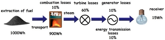
Figure 1.
An example of a conventional energy system.
Modern energy systems are not sustainable. Most of them are based on the production of energy from non-renewable sources. Much of the power contained in fuel is irretrievably lost, and the quality of the energy is lowered. It is accompanied by the emission of fossil fuel combustion products into the atmosphere, which pollutes the natural environment. Despite the passage of almost three decades, Figure 1 is still largely valid, and energy systems based on fossil fuels as well as liquid and gaseous fuels are doing well and are still being developed, even in highly developed countries.
2.1. Environmental Protection Problems
Technologies related to transport, energy generation, heating and the incineration of industrial and municipal waste have the largest shares in the production of gaseous and solid pollutants and their emissions into the atmosphere. The percentage shares of the above-mentioned technologies in the global pollution are [37,38,39]:
- transport (60%): nitrogen, carbon oxides and sulfur compounds, as well as solid pollutants, are the precursors of acid rain, and global emissions of CO2 have increased by over 20% over the last 30 years;
- industry (16%): a source of pollutants of a great variety, the largest amounts of which are generated by the metallurgical, cement and chemical industries;
- energy generation (15%);
- heating (6%);
- waste incineration (3%).
Table 1 shows the side effects and perpetrators of the three most spectacular environmental pathologies—climate change, ozone depletion and acid rain—observed in recent decades as a result of intense technological development. Most of the problems listed in Table 1 are the result of generation, distribution and multiple energy conversions.

Table 1.
Environmental problems: phenomena, perpetrators and effects, reproduced from [17] with the permission of the author. Data were obtained from reference [40].
2.2. Pollution of Air, Water and Soil
Air pollution is the biggest environmental problem, because combustion products in the form of volatile carbon compounds, sulfur and nitrogen are often transported with the wind to regions distant from the place of production. There, reacting with moisture in the atmosphere, they form acids and seep into surface waters with rainfall, causing acidification of the environment, damaging vegetation and adversely affecting water resources and soil.
The production of carbon oxides (CO and CO2) and other volatile organic substances (VOC) is growing rapidly and results in the release of huge amounts of carbon into the environment. Organic carbon compounds containing chlorine, iodine, bromine and fluorine did not exist in the atmosphere in pre-industrial times and are the main cause of periodic ozone depletion in the upper atmosphere (ozonosphere) as well as global warming. Produced in the combustion of fossil fuels and other compounds, sulfur oxides (SOx), hydrogen sulfide (H2S) and sulfurous and sulfuric acids (H2SO3 and H2SO4) are among the main pollutants of the environment. In the presence of water vapor, they form acids that cause acid rain. High-temperature combustion processes generate nitrogen compounds: nitrogen oxides (NOx, NO2, N2O) and ammonia (NH3), which are largely the result of natural nitrogen release from seas and land, but about 40% of these compounds are released during the combustion of fuels and biomass and from the use of nitrogen fertilizers. It is worth mentioning that solid pollutants (dust, soot, coal ash, lubricants, lime, metal oxides, asbestos, silicon compounds (SiO2), antimony, zinc and radioactive isotopes) can have different dimensions, from 30 to 0.01 μm and smaller. Larger particles of solid pollutants quickly settle on the earth’s surface, but smaller particles stay in the atmosphere for a long time, forming aerosols [37].
Water resources and quality are fundamental to life on Earth and to all activities. The main problems with water quality are related to biological and chemical pollution. Biological pollutants are bacteria, viruses and some higher-order organisms that occur naturally in water or that are the result of human activity. They can be a source of diseases and epidemics of a wide range. Chemical pollutants generated during industrial processes, agricultural activities or land and waste management are in the form of sediments from toxic substances, fertilizers and sewage and are the cause of soil contamination. We can see many examples of the negative impacts of technology and human activity on water quality, covering large areas and huge amounts of it. One of such phenomena is industrial and municipal waste, including toxic waste, the storage, neutralization and utilization of which cause air, surface, groundwater and soil pollution. One of the methods of removing magnetic and paramagnetic solid contaminants from water is electromagnetic separation, as well as superconducting.
Soil and land are also subject to adverse impacts related to agricultural activity and the use of artificial fertilizers, which significantly contribute to the deterioration of their biological and chemical quality. The treatment of soil in order to remove harmful bacteria, fungi, mold and organic and inorganic pollutants is carried out by physical methods (high temperature, UV radiation, microwaves and ultrasound), chemical methods (chlorine, methyl bromide, hydrogen peroxide, sodium hypochlorite, ozone, bromine and iodine) and biological methods (microorganisms and bacterial strains producing enzymes and surfactants).
All methods are used to a greater or lesser extent in research laboratories and in practice. Chemical methods are harmful to the environment, and the aim is to limit their use, especially in highly industrialized countries which have committed to the Montreal Declaration to end the use of methyl bromide, CH3Br, as a soil sterilization substance by 2005. Methyl bromide is considered to be a substance responsible for the long-term effects of environmental pollution, including damage to the ozone layer. Hence, there is a need to search for alternative soil sterilization methods and an interest in plasma methods, especially in ozone generated during electrical discharge in air or oxygen, the strong sterilization and bactericidal properties of which are known and have been used for a long time in water and wastewater treatment processes.
Toxic waste, including post-hospital waste, has been a serious problem in recent centuries. Much of this waste is either stored underground or dumped. Building new landfills does not solve the problem. One of many solutions may be the use of plasma reactors for the disposal of toxic solid waste. With this technology, it is also possible to neutralize gaseous pollutants generated in waste incineration processes.
More often, as has been recently observed in nature, ecological disasters that are both natural (earthquakes, volcanic activity, and floods), and those that result from human activities (nuclear power plant disasters, leaks of various chemicals during their transport, fires, etc.) also cause air, water and soil contamination.
The progressive increase in demand for electricity also brings challenges for the power industry in order to develop technologies allowing for the efficient and environmentally compliant generation of electricity. In recent times, the greatest potential opportunities lies in the use of renewable energy sources, solar energy in particular. It can be used to power mobile plasma installations for the treatment of water, air and soil, especially in highly sunny areas, in order to avoid environmentally harmful chemical technologies [31,32].
The proper use of electromagnetic technologies, including superconducting and plasma technologies, has partially reduced the environmental impact of energy generation and conversion processes. It has reduced power losses and has prevented the deterioration of energy quality, but many problems still remain to be solved.
3. Plasma and Superconductivity Phenomena as Media for Power Engineering and Environmental Applications
The development of superconducting and plasma technologies dates back to the beginning of the 20th century, when the phenomena on which they are based were discovered and named. The main factor underlying both phenomena is temperature. Plasma and superconductivity occupy opposing ranges on the thermodynamic temperature scale (Figure 2). The phenomenon of superconductivity is a combination of the magnetic and electrical properties of a material (metals and alloys) manifested by the disappearance of electrical resistance, accompanied by the forces of magnetic ordering. We distinguish between low (temperatures close to absolute zero) and high-temperature superconductivity (30 K and higher).
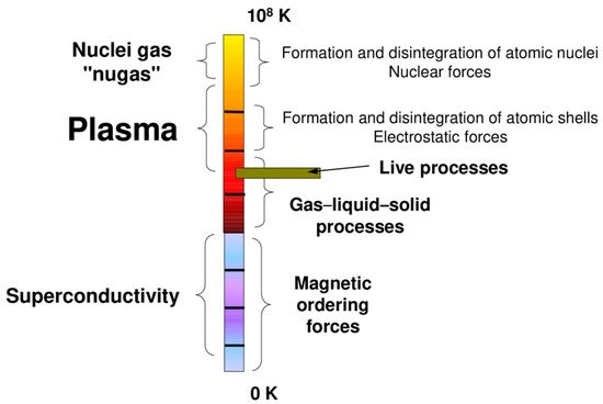
Figure 2.
Thermodynamic scale of temperatures with marked phenomena of plasma and superconductivity.
A much larger part of the thermodynamic scale presented in Figure 2 is occupied by plasma, an ionized gas with electrically conductive properties, known as the 4th state of matter, whose particles such as electrons, ions and neutrals have energies between 0.05 eV and 104 eV. Both phenomena (in addition to the thermodynamic temperature scale) combine the growing possibilities of applications in various areas and scientific disciplines, including those related to the sustainable development of energy and the environment. At the top of the thermodynamic scale, hot plasma with a temperature of 100 MK can be used in the future for the production of electric energy in nuclear fusion in ITER reactors.
3.1. The Plasma Phenomenon: Properties and Classification
The history of plasma research dates back to the mid-eighteenth century, but the concept of plasma was first introduced by the American scientist Irving Langmuir in 1923. Nevertheless, from the beginning of the 20th century, plasma was used technologically as a result of German scientists and industrialists, brothers Werner and William Siemens, who built and applied the first practical ozone generator (1857) and the first arc furnace (1878). Soon after, plasma ozone-generating installations for the disinfection of drinking water in Nice (1907) and St. Petersburg (1908) began to work.
Plasma as a technological medium can be produced in a very wide range of temperatures and pressures. In addition to temperature and pressure, important criteria for the division of plasma are the degree of ionization and the type of thermodynamic and kinetic equilibrium of its particles. At very low pressures, even at a temperature close to ambient, it is possible to generate non-thermal (cold) plasma. At atmospheric pressure, the production of even weakly ionized plasma during electric discharge requires high values of gas ionization voltages and appropriate designs of plasma reactors.
One of the important features of plasma is the ability to control its parameters within wide limits. These include: the chemical composition of the working gas; pressure; discharge geometry; the structure of the electromagnetic field, internal or external; the absence or presence of electrodes; the presence of a dielectric; the volume of the discharge space; and the parameters of the supply system (power, voltage, frequency, number of phases, shape of the supply voltage and internal impedance of the power supply). The power supply system may decide the possibility of the practical use of plasma technology for the improvement of the natural environment and its sustainable development [1,17,41].
3.2. Superconductivity: Properties and Classification
In 1911, Heike Kamerlingh Onnes found that, at 4.2 K, the resistance in a solid mercury wire immersed in liquid helium suddenly vanishes. Since then, research on superconductivity has been developing. The first attempts to build transformers with Nb–Ti low-temperature superconductor windings operating at the temperature of liquid helium were unsuccessful. A total of 75 years after Onnes’s discovery, in 1986, as a result of the research of J.G. Bednorz and I. Müller on high-temperature ceramic superconductors at the temperature of liquid nitrogen and higher, practical applications of this technology became possible. These materials are currently the main group of superconductors used in energy applications (with the exception of a small group of LTS materials used mainly in low-temperature electromagnets for strong magnetic fields) [12].
Superconducting materials, especially in relation to energy applications, are characterized by two important properties: zero (negligible) resistivity and ideal diamagnetism, usually coexisting together with the phenomenon of magnetic flux trapping. The first property allows one to obtain much higher power densities in energy applications than for conventional copper wires, whereas the second one is used in various types of applications requiring magnetic field interactions (such as in magnetic bearings).
The properties of superconducting materials occur basically below a certain temperature, called the critical temperature Tc. For a given superconducting material, the Tc is one of the most important characteristic quantities (defined for the self-magnetic field at atmospheric pressure). This temperature also determines the classification of the superconductor for two main groups of materials: LTS or HTS. There is also a small group of relatively newly discovered materials with a critical temperature in a range between LTS and HTS. This group includes, among others, MgB2, a material having promising properties for energy applications [42].
However, the critical temperature Tc is not the only parameter that defines the occurrence of superconductivity. In order to the obtain superconducting properties of materials, the magnetic flux density Bc and the current density Jc cannot be exceeded. These three quantities, called critical (Tc, Bc and Jc), are interrelated and define the surface of the critical parameters for a given superconductor, such as that which is presented in Figure 3. It determines the maximum possible transport current flowing in the wire under superconducting properties.
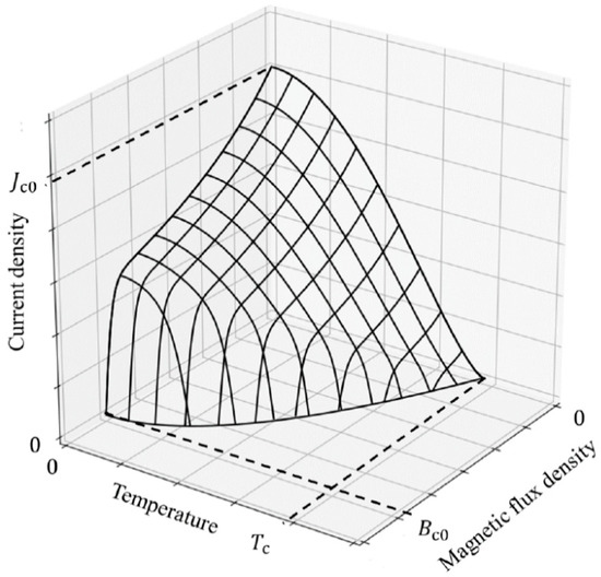
Figure 3.
An example of the surface of critical parameters in a superconducting material.
The critical current density Jc is also indirectly limited by power losses generated in superconductors (power losses are sources of heat, therefore increasing the temperature). The smallest power losses are generated for DC current. Hence, superconductors are the most often used in DC systems, and the critical current densities in such conditions are the highest. Additional power losses (generally known as AC losses) occur in AC systems. Within these losses, two basic components can be defined: transport losses and magnetization losses. The occurrence of AC losses causes superconductivity in AC applications to exist only in the grid frequency range. The most common applications are transformers and armature windings of AC motors (existing together with an excitation winding in what is known as a full superconducting motor) [43]. Thus far, attempts to develop high-frequency AC applications, such as wireless power transmission, have not been successful [44].
The transition from superconducting to a resistive state in superconductors, called a quench, is most often an undesirable phenomenon, and when it occurs in an uncontrolled manner, it usually leads to the destruction of the device. However, there is an area of superconducting applications that exploits the quench transition. These applications are superconducting fault current limiters (SFCL). This class of devices have several different types and use different properties of superconductors.
The examples of superconducting applications presented above are related mostly to the zero resistivity property. These applications are constructed usually with a superconductor as an electrical wire (conductor). However, there is a group of superconducting applications that takes advantage of another property of these materials: ideal diamagnetism (most often together with magnetic field trapping). In such applications, superconductors most often are in the form of a massive superconductor (bulks). In a superconductor, placed in the presence of a magnetic field, a strong eddy current is induced, shielding the interior of the superconductor from the external magnetic field. Hence, such a superconductor behaves like an ideal diamagnetic material. This property is used in magnetic shielding systems and in passive levitation systems (the superconductor, as a diamagnetic material, does not require additional stabilization in the levitation system). Additionally, if the superconductor is cooled down in the presence of an external magnetic field, this field is trapped on defects of the superconducting lattice. The effect of “remembering” the shape of the external magnetic field in superconductors is observed. This property is mainly used in levitation systems and in magnetic bearings. Trapped magnetic fields cause the levitation phenomenon to occur regardless of the direction of the gravity force, and the operation of magnetic bearings in any position in relation to the force of gravity is possible.
To summarize, the applications of superconductors for energy generation, conversion and transmission can be divided into two main groups with respect to the conducted current (DC and AC) and into three groups with respect to the employed property (zero resistivity, ideal magnetism/flux trapping and quench transition). The most important applications dedicated for the energy sector are presented in Table 2.
Table 2.
Applications of superconductivity in energy conversion.
The properties of superconductors mentioned in this section and listed in Table 2 demonstrate only the basic possibilities of the use of these materials in energy applications. More detailed descriptions of superconducting applications and their potential in the field of electrical engineering and energy are presented in Section 5.2 of this paper.
4. Review of Plasma Applications for Energy and the Environment
Contemporary applications of plasma reactors are material, chemical, and environmental protection technologies as well as biotechnologies.
The transformations of the physicochemical properties of gas, as well as its momentum and energy as a result of electrical discharges occurring in it, are the basis of plasma applications in various areas. Processes such as surface modification, etching, thin layer deposition, powder production, ozone production, plasma gas and wastewater treatment, thermal waste treatment, etc., result from changes in the physicochemical properties of plasma particles. Obtaining plasma beams for laser technology, rocket propulsion, radiation generation and plasma light sources is possible as a result of the momentum and energy transformations of plasma particles. Light sources and metallurgy are the oldest plasma technologies used in practice.
The last decades of the twentieth century were another renaissance of plasma methods and new applications for already-used electrical discharges, which have always been the main source of plasma for technological purposes. These include such large areas of application as: micro-electronics; technologies for the production of semiconductors; superconducting; and organic, bio- and nanomaterials.
The twenty-first century is the era of new materials and their production technologies, which are now mostly based on plasma and laser technologies. The latter are closely related with plasma, which is often a medium that strengthens laser beams (laser pumping) and are classified directly among plasma technologies.
Non-thermal plasma, generated by electric discharges, has more and more often been used in biotechnologies as a medium that enables biochemical processes to be carried out at an atmospheric pressure, at ambient temperatures and without waste that is harmful to the environment.
The environmental applications of plasma generated by discharges in air or in oxygen include [15,16,17,18,19,20,21,22,24,25,26,27,30,45,46,47,48,49]:
- reducing nitrogen oxides from flue gases from natural gas combustion: removing nitrogen oxides NOx, sulfur dioxide SO2, heavy metals and volatile organic substances (VOC) generated in the processes of painting, varnishing and waste incineration disposal and in other chemical processes;
- recycling and removing pollutants: the decomposition and incineration of organic, volatile and solid waste; exhaust gases from diesel engines; used batteries, and printed circuit boards, by using arc and quasi-arc plasmas;
- supporting chemical reactions: the selective removal of acetylene from ethylene; the decomposition of ethylene, trichlorethylene, ethyl acetate and toluene; the production of gaseous hydrogen and soot through the decomposition of hydrocarbons.
Thus far, many types of both warm and cold plasma reactors used in processes related to environmental protection have been tested. The main electrical discharges that generate warm equilibrium plasma are arc discharges (AD), microwave (MWD), plasma torches (PT) and plasmatrons, whereas non-thermal (cold) and non-equilibrium plasma are produced by barrier dielectric discharges (DBD), atmospheric pressure glow discharges (APGD), corona (CD) and gliding arc (GAD) [16,22,24,25,50,51,52,53,54,55,56,57,58,59,60].
The potential of these devices has been confirmed many times in the removal of nitrogen oxides NOx, sulfur dioxide SO2 from flue gases and heavy metals and volatile organic compounds VOCs produced in painting, varnishing and chemical processes. Plasma molecules easily react with various chemical substances, which allows for the decomposition of toxic compounds, the modification of polymer structures, etc.
Research works on the use of plasma in technologies related to environmental protection are aimed at, among others:
- the assessment of the suitability and effectiveness of various types of electrical discharges for the production of non-thermal plasma, especially at atmospheric pressure;
- improving the process of generating electrons initiating the process of removing pollutants;
- achieving the desired composition of the final gas mixture and a high degree of conversion of harmful compounds by adding admixtures and catalysts (water vapor and ammonia);
- minimizing energy consumption;
- matching the electric power source to the plasma reactor.
The chosen applications of both thermal and nonthermal plasma for energy and the environment are reviewed in the next subchapter.
4.1. Plasma in Reducing Greenhouse Gas Emissions
An important research topic of environmental protection is global warming associated with the excessive production of greenhouse gases, among which the most important role is carbon dioxide (CO2) as a product of fossil fuel combustion. The main reason for the increase in CO2 emissions is the increasing energy demand and dependence on fossil fuels, which cover 70% of the world’s energy demand. CO2 emissions can be reduced by various chemical and thermal methods, such as thermolysis (electrolysis at high temperature), thermal catalysis, photocatalysis and thermal conversion by microwave heating desorption, radiofrequency and inductive heating [48,61,62,63].
Alternatives to these methods are plasma-based ones [16,19,22,46,49,64]. Converting CO2 into other useful products has been considered a great challenge for the past few decades. In [64], the application of plasma methods consisting of direct air conversion (DAC) and conversion for “power to gas” via syngas production, as well as the conversion of CO2 from power plant emissions, were considered, and the current problems and recommendations of plasma methods for the future were analyzed.
Figure 4 presents a plasma-based DAC of CO2 for energy storage via syngas production. The excess electricity generated from renewable sources can be used to power a plasma process to capture CO2 from the air and convert it into carbon monoxide (CO) and hydrogen (H2) produced from electrolysis, which is also powered by renewable electricity. CO and H2 can be produced and fed to a downstream process, such as CO2 methanation, Fischer–Tropsch (FT) synthesis and methanol synthesis. The end products, including methane, methanol and other valuable hydrocarbons, are used as fuel for the production of various chemicals, for electricity generation or for domestic applications, such as heating.
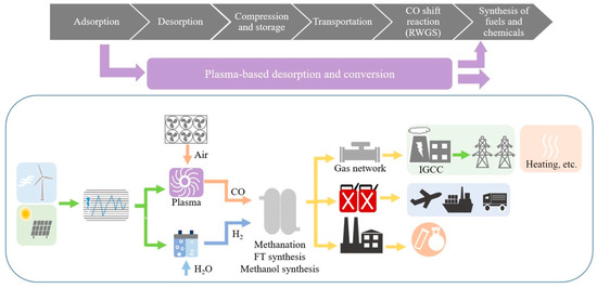
Figure 4.
Plasma-based direct air capture of CO2 for energy storage via syngas production. Reproduced from reference [64], published under the license CC BY 4.0.
Because plasma technology does not require a long start-up, it is possible to desorb and convert CO2 under very dynamic power conditions, ensuring the possibility of satisfying the discontinuous demand for balancing the dynamic generation of electricity from renewable sources. The process uses only air, water and renewable energy as input and has all the benefits of plasma technology, providing an environmentally friendly solution for CO2 conversion and energy storage. It can also serve as an alternative to coal gasification or non-CO2 neutral natural gas reforming.
Plasma-based technology is constantly under development. Its energy efficiency cannot be directly compared with mature thermal and chemical conversion technologies. Plasma technology installations are more compact, have faster response and reaction times and are relatively cheaper compared to conventional gasification and reforming. A target of 60% efficiency has been proposed in the literature to make plasma CO2 conversion competitive with existing processes, and some types of plasma, such as GAD or MWD, are very promising in this respect [16,64].
Plasma has a high CO2 conversion potential compared to other techniques due to many factors, especially: its operation at low temperatures, the possibility of using renewable energy technology to meet its energy requirements, low investment and operating costs of the reactor and its independence during operation from rare earth materials.
Studying carbon capture and utilization processes is very important for the future development of CO2-neutral fuel production [65,66,67]. The main idea of such processes is rendering CO2 neutral in a way of capturing it directly from the initial hydrocarbon production sources, such as fossil fuel power stations, metallurgic and cement plants and vehicles, sea ships and aircrafts [65]. The use of high-frequency plasma reactors is considered to be an effective method for CO2 dissociation in such processes [68]. The dissociation kinetics of CO2 is supported by the vibrational excitation of its molecules resulting from intermolecular or molecule–electron collisions. Such interactions provide necessary energy for molecules achieving a continuum region of excitation. Diomede et al., in [68,69], numerically studied CO2 dissociation in plasma by using the non-linear Fokker–Planck equation and Monte Carlo method for time-dependent diffusion as well as a flux-matching approach. The authors developed a new numerical approach for vibrational problem solving, which can be effectively used in multi-physical plasma reactor models by contributing to their cost reduction.
An important group of study in the field of air purification is the influence of catalysts on the efficiency of pollutant conversion [48]. In [70], VOC removal efficiency was investigated with the aid of a packed-bed DBD reactor. The presence of packing materials increases the removal efficiency, reduces the formation of unwanted by-products and enhances CO2 selectivity. Packing the DBD reactor with porous packing material additionally suppresses NOx formation. The research presented in [70] proved that many factors influence the characteristics of the DBD packed-bed and the efficiency of VOC removal. These are influenced by various properties of the dielectric packaging materials, such as the dielectric constant, size, shape and surface properties of the electrodes and the pore dimension of the inter-electrode material.
To remove solid impurities from exhaust gases, e.g., from coal combustion, the technology based on the electron beam EB is used, which is classified as plasma technology and is used to remove sulfur, nitrogen oxides, volatile organic pollutants and polyaromatic hydrocarbons and to reduce dioxin emissions from municipal and medical waste incineration plants, which is a great challenge now [71,72].
4.2. Selected Air Purification and Gaseous Media Cleaning Processes
Devices for the generation and application of low-temperature plasma are often important elements of the installation of industrial waste gas treatment. Waste incineration gases contain sulfur compounds SO2, SO3, nitrogen NOx, carbon dioxide CO2, ammonia NH3 and volatile organic substances. Following the full implementation of the Gothenburg Protocol [73], sulfur emissions in Europe should be reduced by at least 63%, NOx emissions by 41%, VOC emissions by 40% and NH3 emissions by 17% compared to 1990 [35].
There are several methods by which we can remove air pollutants from waste treatment exhaust gases; these are: (1) electrostatic precipitators for dust particles, (2) water scrubbers or adsorption filters for gaseous pollutants and (3) chemical and plasma methods to convert pollutants into harmless or useful products.
One of the most important issues of the modern automotive branch is finding ways for reductions in pollutants emitted by diesel engines. The pollutants include carbon monoxide (CO), unburned hydrocarbons (HC), nitrogen oxides and particulate matter (PM) [74,75,76,77,78]. Diesel particulate matter (DPM) is considered to be the most complex component; it is composed of the solid fraction, the soluble organic fraction (SOF), sulphate particulates (SP) and nitrates (in a form of nitric acid HNO3). The solid fraction is a soot and includes elemental carbon and metallic ash, composed of metal oxides, phosphates and iron oxides derived from the corrosion manifold [75]. The SOF depends on the diesel engine design and its operation parameters. It appears as a result of unburned fuel and lube oil, and it includes heavy hydrocarbons [74,76]. The SP fraction (SiO2, partially sulphates) forms after the chemical reaction of sulphuric acid water from exhaust gas. The most common well-established technologies for presented pollutant reduction are diesel particulate filters (DPF) [79], diesel oxidation filters (DOC) [80], selective catalytic reduction (SCR) [81] and particle oxidation catalysis (POC) [82]. The mentioned technologies are far from perfect and struggle with a wide variety problems [74]; hence, the development of new solutions is required.
One of the very promising and efficient techniques for diesel exhaust gas (DEG) treatment was found to be the atmospheric pressure plasma (APP) method [77]. According to [76], the most recent plasma reactor types used for this purpose were found to be DBD and corona discharges in different configurations: planar DBD, cylindrical DBD, surface discharge, pulsed corona discharge and ferroelectric pellet packed-bed reactor. The most important parameters for DEG plasma treatment are configuration type, discharge mode, voltage polarity, amplitude and frequency of plasma generation.
Figure 5 presents the mechanism of the APP treatment of DEG. Plasma-generated radicals cause significant oxidation effects on DPM fractions at low temperatures.
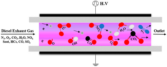
Figure 5.
Most common configuration for plasma reactors in DEG treatment applications. The arrows show the trajectories of the ionized particles after collisions from the treatment gas inlet to the outlet. Reproduced from reference [76], published under the license CC BY 4.0.
For example, the further oxidation of NO to NO2 enhances the decomposition of PM gathered in DPF, which the following reactions demonstrate [83,84]:
●OH radicals react with C, resulting in CO2 or CO and H appearance [85]:
The e/M component indicates the ratio of charge of an electron to its mass.
Allamsetty S. and Madhukar A., in [77], presented a very comprehensive and informative review of the discharge plasma treatment of NOx in diesel engine exhaust. The authors concluded that the type of energisation, frequency and magnitude of voltage signal, and repetitive pulse energisation are the parameters that have the most significant impact on the effectiveness of the NOx plasma treatment. The type of energisation (pulsed/ac/dc) on the NOx treatment was also investigated in [86,87]. The authors found that, among the tested supply systems, pulsed energisation exhibits the highest NOx-removal efficiency. The authors of [88] include a comparison of another set of supply sources: solid state pulse sources, high-voltage ac sources (HVac) and high-frequency ac sources. This time, the most efficient in NOx-removal was HVac. The authors of [89] describe the effect of peak voltage, frequency and engine load on NOx, HC and DPM removal. The authors performed the experiment with the use of a DBD setup and observed a decrease in NOx removal efficiency while the peak voltage increased. Increasing the frequency from 13 to 15 kHz perceptibly improved the removal rate. Another paper [90] reported the impact of the voltage, frequency, gas flow rate and the use of γ-alumina pellets on removal rate, where the experiment was conducted by using a multi-rod DBD reactor. The obtained results show improvements of the removal rate, while both voltage and frequency increased. The tests demonstrate the importance of the DBD reactor configuration, which affects removal efficiency. Repetitive pulse energization impacts were associated with the separated influences of signal parameters, such as pulse repetition rate, pulse width effect, effect of rise time and discharge mode. A detailed description of this investigations can be found in [91,92,93,94].
Hołub et al., in [74], described the influence of a direct non-thermal plasma (NTP) treatment on DPM and NOx in the exhaust of a marine medium-speed diesel engine. The NTP reactor was constructed by using DBD technology, as described in [95]. The experiments were carried out with generated energy densities from ~3 J/dm3 (low level) to ~16 J/dm3 (substantial level). The authors reported very significant NO and PM conversions at realistic exhaust conditions. A maximal removal rate of about 12% was achieved by using 265 W of input active power, and a total PM removal efficiency of ~1.7 g/kWh was observed in the 180 W input mode. Plasma treatment also caused the partial oxidation of NO to NO2, supporting the NOx-catalyst-based reduction processes.
Continuing the research topic of NOx and SiO2 emissions in marine engine systems, Chmielewski et al., in [96], revised the plasma methods of reducing emissions. A combination of microwave and DBD technologies allows one to achieve nearly full reduction in NOx and SiO2 from two-stroke diesel engine exhaust fumes, which was confirmed by laboratory experiment with the use of a flow rate of 20 L/s [97]. Works [98,99] present a way for dust and nitrogen oxides to be removed from exhaust gases emitted by marine engines with the use of plasma-generated ozone. After the initial dust filtration, it is oxidized with the help of ozone. Nitrogen oxides contained in dedusted gases are adsorbed, then desorbed and reduced as a result of using NTP treatment. Researchers achieved high removal efficiencies of up to 94% for nitrogen oxides and 95% for dust; the exhaust flow rate in laboratory conditions was 700–800 m3/h.
The plasma oxidation of NO particles is a desired reaction, assisting the purification of exhaust gases from NOx compounds. European scientists compared the direct and indirect plasma oxidation of NO combined with oxidation by a catalyst [100]. The coaxial DBD reactor for direct treatment included a stainless steel tube (inner electrode), a quartz tube (dielectric) and a metal mesh wrapped around the quartz tube (outer electrode). The AC voltage supply was 14 kV, and the frequency ranged from 50 to 1000 Hz. A similar setup excluding the outer electrode was used for indirect treatment for ozone generation purposes. The gas flow tube of the second (catalytic) reactor was coated by a TiO2 catalyst powder, as shown in Figure 6; since the TiO2 catalyst needed thermal activation, the reaction zone was heated to 70 °C.
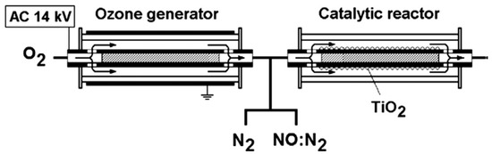
Figure 6.
Experimental apparatus for indirect plasma treatment of NOx. Reproduced with permission from [100], Elsevier, 2022.
The authors used optical absorption spectroscopy for the determination of NOx, N2O5 and ozone concentrations. The experimental setup and chemical composition measurement methodology are described in detail in [101,102]. The researchers found that an inlet NOx concentration of 200 ppm at an ambient temperature exhibits very similar results. The increase in temperature in the DBD reactor caused reductions in direct oxidation efficiency. Substantial oxidation efficiency was obtained for the indirect approach at residence times below 10 s and with a flow rate of 3 m3/h. The experiment with the TiO2 catalytic powder demonstrates significant efficiency gain in NOx oxidation for small-scale tests; however, the medium-scale experiments show negligible oxidation improvement. Jogi et al. concluded that the enhancement of NOx oxidation with the use of a catalyst strongly depends on higher gas flow rates, giving a shorter reaction time.
Promising alternatives to removing pollutants from gases and liquids are technologies that use non-thermal plasma generated by a gliding arc discharge GAD [1,17,31,32,41,47,51,59,63]. Plasma reactors can be used both to remove point pollutants, such as factory and utility chimneys, and to control pollution caused by traffic [18,38,47].
The authors of [72] presented a gliding-arc plasma generator used to remove hydrocarbon-containing compounds. Gases emitted during the painting and drying of the casting molds were contaminated with heptane, toluene, xylene, butanol, turpentine and ethyl acetate. Their plasma removal using a GAD was tested on a pilot installation of the foundry’s production line. The satisfactory efficiency of removing the above-mentioned hydrocarbons was obtained with relatively low energy demand, ranging from 4 to 28 kWh per 1 kg of mineralized hydrocarbons.
The cold plasma generation technology can be also used in spectrometry devices for the determination of the chemical compositions of gaseous media, especially in experimental setups for CO2 and O2 removal from organic aerosols. For this purpose, a new approach, relying on the use of inductively coupled plasma (ICP) optical emission spectrometry (OES), was proposed by Austrian researchers in 2014. The principle of operation of the ICP-OES technique is based on the registration of the light of excited atoms resulting from their transition to a state of lower energy; it allows one to determine the concentrations of certain elements in a tested sample. The researchers used an online combustion system including an RF-powered ICP torch, as shown in Figure 7.
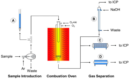
Figure 7.
Experimental setup of the online combustion system: (A) overpressure safety section, (B) falling-film glass-tube column, (C) hollow fiber gas device, (D) commercial desolvation device. Reproduced from reference [103], published under the license CC BY 3.0.
The experimental setup comprised three main sections: the sample introduction section, where 10 mg kg−1 sample solutions of Ag, Ba, Cd, Cr, Fe, La, Li, Mg, Ni, Pb, Y, Zn and Zr in dichloromethane and dichloromethane were nebulized; a combustion oven, where the produced aerosol additionally mixed with argon and oxygen that was then burned at a temperature of 1050 °C; and a gas separation device, where the removing of CO2 and excess O2 from the combusted aerosol was carried out. The researchers reported very high efficiency (even up to 97%) for CO2 and O2 removal from the tested samples after the end of the technological cycle. Since the organic solvent aerosols analyzed by ICP in most cases require high-power RG generator standards, the tested solutions were investigated with the use of 1650 W and 1400 W supply modes. Decreases in RF power resulted in signal suppression in all atom and ion emission line spectra. Wiltsche et al. also concluded that optimal and stable ICP operation is constrained by the amount of oxygen in the carrier gas stream. Moreover, the proposed approach can be applied for the quantitative determination of trace metal ratios in highly volatile solvents.
4.3. Transformation and Valorization of Industrial Waste
Industrial and municipal waste, including toxic and post-hospital waste, is a serious problem for the natural environment. Despite significant progress in this regard, technological difficulties still arise, which limit the achievement of the expected ecological and economic benefits. In works [15,27,28,60], a review of plasma technologies in the management of solid and liquid industrial and municipal waste was performed. Examples of the thermal technology of plasma generated in arc furnaces, used on an industrial scale in the metallurgical processing of materials, are given.
The process of plasma gasification for sewage sludge, given in Figure 8, depicts plasma reformer technology for the removal of acidic natural gases present in syngas. For this purpose, there is a quick quenching mechanism which cools the gas just after its production to avoid further chemical reaction, which can result in dioxins. Heavy metal and hydrogen sulphide absorbents are also inserted to remove toxic gases. Chemicals that are basic in nature are placed to neutralize acidic components in syngas. The input sludge for processing and the amount of energy required to generate plasma decide the quality of syngas. Optimization is required among input heat, moisture, pressure and sludge to produce hydrogen-rich output gas [60].
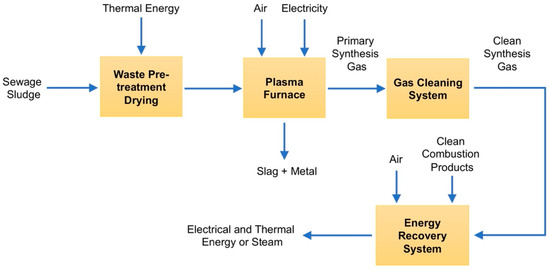
Figure 8.
Block diagram of syngas production from sewage sludge using plasma reformer technology, prepared on the basis of the data contained in [60].
Despite high advancements in thermal arc plasma technology for environmental protection, research is still being conducted in the world on processes of converting industrial and municipal waste into energy and liquid and gaseous fuels [26,27,104]. Electrical discharge plasma has been used for decades in fuel transformation and combustion systems. Initially, it was used as a heat source to start the combustion process. Much research concerns the catalytic properties of plasma due to the complex nature of the phenomena occurring in the reactions of fuel reforming [105].
The most common plasma sources used in fuel reforming are DBDs, MWDs and GADs, but other types of discharges are also used, such as corona, RF, spark, glow and pulsed [16,105,106]. Plasma fuel reforming technologies have great advantages and bright prospects. The synergistic effects of plasma technology can also play a key role in the future of fuel cell technology.
The source of renewable energy may be the combustion of biomass in the pyrolysis process, which, however, is associated with the emission of tar and aromatic hydrocarbons responsible for the greenhouse effect. This can be partially prevented by using systems with appropriately selected catalysts. Such a coupled plasma-catalytic system (CPCS) for toluene conversion was investigated in [106], and its effectiveness was compared with a homogeneous plasma system with a GAD.
The most commonly used catalysts for tar decomposition purposes are Ni, Rh, Pt and Fe-based compounds. The studied CPCS system has used the RANG-19PR, which is the industrial catalyst for the methanation of carbon oxides. The authors found that the gliding discharge plasma generation technique is effective technology for toluene decomposition in the case of pyrolysis gases with a low amount of toluene. Regarding gases containing high toluene concentrations, CPCS with RANG-19PR allows one to achieve higher toluene conversion than a gliding discharge system. Adding to the plasma zone of Ni + NiO/Al2O3 compounds significantly improves the conversion rate of toluene (up to 89%) and the methanation of carbon oxides.
Arc furnaces are also used in the processes of the recovery of materials from the steel industry and steel processing; the recovery of precious metals from the platinum group from used catalysts; and the disposal of asbestos-containing waste and radioactive, electronic, oil, petrochemical and mining pollutants. These wastes contain both hazardous materials that can have a very detrimental effect on local ecosystems, and they can also be valuable elements, usually precious metals [15].
The treatment of solid waste by plasma is usually associated with the thermal utilization of waste. Among those, the gasification technique is rather well researched and is applied on an industrial scale. Gasification is not incineration; in plasma gasification, the waste input is pyrolysed by high temperatures into its constituent elements: H2, O2, C, N2, etc. The converter conditions are controlled; therefore, prior to exit, the elements reform into the desired syngas that is rich in CO and H2.
The materials that cannot be converted into syngas, such as metal, glass, rock and concrete, are vitrified to produce an inert slag. The slag is 1/250 of the volume of the processed solid waste. Plasma arc gasification is waste-treatment technology that uses high electrical energy and high temperatures created by an electrical arc gasifier. This arc breaks down waste primarily into elemental gas and solid waste (slag) in a device called a plasma converter. The process has been intended to be a net generator of electricity, depending upon the composition of the input wastes, and to reduce the volumes of waste being sent to landfill sites. Four types of gasifier processes are currently available for commercial use: counter-current fixed bed, co-current fixed bed, fluidized bed and entrained flow. Figure 9 presents an exemplary plasma arc solid-waste-treatment technological process including recycling, aggregation and syngas cleaning possibilities.
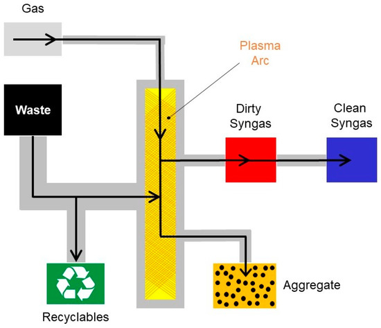
Figure 9.
Solid waste treatment using plasma arc. Reproduced from reference [15] published under the license CC BY-NC-ND 4.0.
To be economically competitive, environmentally acceptable and readily available, alternative fuels must be technically feasible. Such fuels include biodiesel, methanol, ethanol, hydrogen, boron, natural gas, LPG, synthetic diesel fuel, electricity and photovoltaics. Although it can be produced from non-renewable sources (methane, coal, nuclear energy), hydrogen’s attractiveness as an alternative fuel is determined by the possibility of producing it from various renewable sources, such as water, wind, solar energy or biomass combustion [20,25,52].
The use of hydrogen in fuel cells, already used in distributed energy and road transport, allows one to significantly increase the efficiency of currently used technologies and to avoid major emissions causing the greenhouse effect [20,53].
5. Review of Superconductivity Applications for Energy and the Environment
As mentioned in one of previous sections describing the basic properties of superconductors, the two main types of superconducting applications are: using zero resistance and using ideal diamagnetism. With respect to a variety of applications, the first group is much wider than the second one. The applications in the first group can be broadly divided to DC and AC applications. The DC applications are mainly various types of electromagnets, DC windings (excitation) in electric machines and DC transmission lines (cables). The group of AC applications relates mostly to grid applications. It includes AC transmission lines, transformers, AC windings of electrical machines and fault current limiters. Superconducting applications using ideal diamagnetism and magnetic field trapping are mainly levitation systems, magnetic bearings, electrical machine excitation systems and magnetic shielding systems (including the previously mentioned fault current limiters). In the next part of this section, superconducting applications are described in divisions according to the method of electrical energy conversion: electrical machines, devices for improving energy quality, and devices for grid applications (distribution network).
5.1. Superconductivity for Electrical Machines
Electrical machines are most often used in energy generation systems (generators) and for energy conversion to mechanical energy (motors). With respect to a constructional point of view, these devices have a very similar structure. Superconductors are used most often in synchronous machines, where the excitation winding is made of a superconducting wire. Recently, intensively developed solutions are machines where the excitation is produced by bulk superconductors with trapped magnetic flux [107]. There are also tests of electrical machines with armature windings made of superconductors (together with a superconducting excitation winding, it constitutes a full superconducting machine). Armature winding can be created as a fully HTS winding or a hybrid structure. Examples of structures of armature windings in PM-excited (permanent magnet) machines are presented in Figure 10 [108].
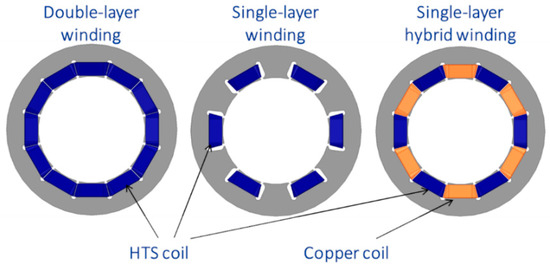
Figure 10.
Different structures of armature winding designs for PM-excited machines. Reproduced with permission from [108], IOS Press, 2022.
The most common applications of machines with superconductors are various types of generators for applications in the production of electricity from renewable energy sources [109] with a power of hundreds of kW to several MW, in particular for wind farms [110], but also for hydropower [111].
Superconducting motors are the most often used in solutions where the working space for the machine is limited. Superconducting motors are about 30% smaller in mass and almost twice as small in volume compared to conventional machines. They are produced in a wide range of rated powers. There are known, for example, low-speed motors for use in ship propulsion, and solutions developed by AMSC with a rated power from 5 to over 30 MW [112,113]. Electrical machines with superconductors are promising actors for industrial applications. Their development is also supported by the development of cryogenic technology that allows the generator to operate at a temperature lower than the temperature of liquid nitrogen (LN2).
5.2. Superconductivity for Energy Storage and High Field Applications
A wide range of superconducting applications has been developed in the field of magnetic field energy storage and the generation of strong magnetic fields (both HTS and LTS materials). Energy storage systems in superconducting coils have been developed for many years, and many solutions with different ranges of stored energy are known. Superconducting coils enable the transfer of large power (kW–MW) in a short time (milliseconds to seconds) [114]. Such parameters of energy transfer allow the use of SMES energy storage to improve the quality of energy in sudden grid events, and, in fact, the only limitation is the link-power electronic system for connecting the coil to the grid [115].
In SMES coils operating in the range of DC currents, the basic limitation is the magnetic field penetrating the coil, both in regard to the magnitude of the magnetic field and its direction (superconducting tapes creating the windings are strongly anisotropic in relation between critical current density and the magnetic field). The most common systems are wound with what are known as pancake coils. Due to the windings connected in series, the magnetic field penetrating the outermost pancake produces the lowest critical current density, and it is of key importance. Therefore, there are reported studies where shapes other than a cylindrical coil were searched for. However, these solutions were associated with much more complex technological processes and most often were not implemented in practice.
The phenomenon of ideal diamagnetism and the trapping of the magnetic field allow one to obtain very interesting properties of magnetic bearings, used mostly for kinetic energy storage with energy accumulated in a spinning mass. Bulk superconductors allow for the production of very stable levitation systems with high levitation forces. Such solutions were proposed, for example, by Boeing, which developed kinetic energy storage with a spinning mass having a rated energy of 5 kWh and a power of 100 kW [116].
Superconducting magnetic bearings are also widely tested for applications for the suspension of drive systems, in particular traction vehicles. Such solutions are expensive, but they have significant potential for industrial applications; hence, there is a wide interest in their development in research centers.
Large groups of energy applications based on superconducting magnets with high magnetic fields are devices for magnetic separation. Such devices are applied for the separation of granular mixtures having ferromagnetic pollutions, in particular elements such as iron, nickel, cobalt and some lanthanides such as samarium or dysprosium. Such admixtures can significantly change the properties of the materials, so separation and removal are very often necessary. There is a variety of separator types. An example of a carousel magnetic separator is presented in Figure 11 [1].
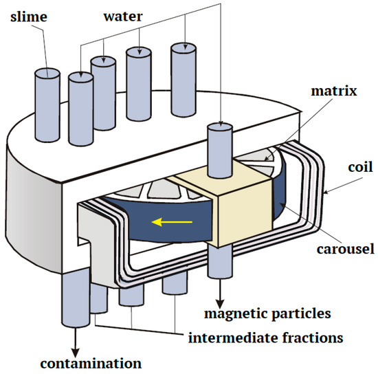
Figure 11.
Schematic diagram of a superconducting magnetic separator: carousel type. Reproduced from [1] with the permission from the author H. D. Stryczewska.
Other examples of the application of superconducting technologies in environmentally friendly energy conversion systems are devices for induction heating based on the principle of power loss generation by eddy currents.
The billet located as a rotating mass in the presence of a strong magnetic field results in induced eddy currents; hence, there is power loss inside the billet. The DC superconducting magnets are used for this process to create a strong external magnetic field. The use of such a magnetic field source allows one to increase the efficiency of the process from 50 to 80% [117].
5.3. Superconductivity for Grid Applications
A significant group of applications designed for energy, ensuring high efficiency and power density in comparison to the classical (copper) solutions, are superconducting devices intended for application in a distribution grid. As mentioned earlier, AC conduction in superconductors involves additional power loss, but they are small enough to obtain better properties than classical solutions. This group of devices includes power cables, transformers and fault current limiters (SFCL). The first two groups of devices work only in the superconductivity state, whereas the last one includes devices operating in the transient state (with quench transition)
Power cables are a group of devices operating both in DC current systems and in the range of grid frequency, making a connection between transformers in substations [118]. There are known pilot installations containing power transmission lines [119]. They are characterized by very high energy densities and low power loss. In AC current systems, both single-phase and three-phase cables are produced. The three-phase systems are constructed as three single-phase cables or as a three-phase common core cables. Cable installations are most often cooled with liquid nitrogen in a circulation system.
Superconducting transformers are most often compact devices with high energy densities. There are known solutions of transformers from what is known as the warm and cold magnetic core [120]. In systems with a warm core, where only the windings are cooled down by a cryogenic system, the magnetic core operates at an ambient temperature. This solution allows one to reduce power loss in the magnetic core, but the magnetic coupling is weaker. In cold transformers, the cryogenic system covers the entire transformer (windings and the core). In such a solution, losses in the magnetic material are higher, but there is no increased distance of thermal insulation between the windings and the magnetic core. Superconducting transformers can also play a role of galvanic separation, having a turn-to-turn ratio of 1:1 [10].
Superconducting fault current limiters (SFCLs) allow for the limitation of short-circuit currents in power grids. They act by quenching from superconductivity to a resistive state and by introducing additional impedance into the circuit. The main advantage of such devices is a very short reaction time (shorter than a single period of the flowing current) [121]. There are many different solutions of limiters. The most popular are resistive-type limiters, inductive-type limiters and limiters with a DC biased magnetic field [122]. SFCLs are a group of superconducting devices with the biggest potential for industrial applications. The only operational difficulty of such devices is the dissipation of the energy released during the current limitation. When the energy is effectively dissipated the limiter is able to operate for a long time with multiple quenches, without the need to replace components or restart the system. In order to ensure proper operation of the SFCL, superconducting materials devoted for such applications are examined both experimentally and by numerical simulations [123].
There are also solutions where a superconducting device, for example, a transformer, is constructed in such a way that, in the event of a short circuit, it can fulfill the function of a current limiter [124]. This type of application is not possible in classic devices, and it allows reductions in the number of devices in the energy distribution system.
In summary, the above-described applications of superconductors in energy conversion allow one to obtain a significantly higher power density than in conventional devices and an increase in efficiency during energy conversion. Therefore, with respect to energy conversion, superconducting devices have a beneficial effect on the environment due to reductions in power loss.
6. Thermonuclear Fusion as an Example of the Application of Hot Plasma and Superconductivity
Hot plasma, with temperatures in the hundreds of millions of Kelvin, which is 10 times the temperature of the interior of the Sun, can be produced by a controlled thermonuclear reaction that fuses two lighter nuclei into one heavier one. As a result of fusion, apart from the new nuclei, free neutrons, protons, elementary particles and alpha particles can also be formed.
The nuclear fuel is completely ionized plasma, perfectly electrically conductive; it is a mixture of deuterium and tritium, made from lithium. The energy content of the lithium resource that is used to produce tritium in the D-T cycle is likely to be greater than the energy content of fossil or uranium fuels, and the fusion fuel is virtually limitless [33,125,126]. Negative deuterium and hydrogen ions can be produced in ion source plasmas using dissociative electron attachment (DEA) and dissociative recombination of H2+ and D2+ or H3+ and D3+ ions [127,128]. DEA reactions for H− and D− production require low-energy (cold) electron beams and are substantially dependent on the initial molecular state, where initial vibrational and rotational electronic energy levels play a decisive role [129].
Another way for hydrogen/deuterium ion production is using negative ion sources, key aspects of which are beam intensity, quality and stability. Starting in 1962, these kinds of sources have been intensively studied [129,130]. The first widely researched system was a double charge exchange system, whose advantages were high reliability and intensity of initial H+ and D+ ion beams [131,132]. The next generation of negative ion sources were the what are known as “surface plasma sources” with pulsed magnetrons [133]; however, the short duration of magnetron beam was disadvantageous for fusion quasi-steady-state plasma heating. The application of the negative ion volume production mechanism in ion sources with magnetic filters and “plasma grid” front end electrodes as well as “tandem multicusp” configurations provided substantial improvements in that issue [134,135]. Introducing Cs into the volume ion source resulted in negative ion current enhancement and reductions in the coextracted electron current, as described in [136]. Since that finding, the injection of Cs into large negative ion sources developed for fusion plasma heating became routine [129]. Recent reports on the sources for the production of negative deuterium ions for fusion plasma heating concern ion sources with external antennae, where the reliability of the source operation is improved [137].
Nuclear fusion does not emit greenhouse gases or long-lived radioactive waste that is the product of fission reactions. There is no possibility of an uncontrolled fusion reaction because the amount of fuel in the reactor chamber is sufficient to sustain the reaction for at most a minute. Under laboratory conditions, the most effective nuclear fusion reaction today is the fusion of deuterium and tritium, i.e., isotopes of hydrogen with one and two neutrons in the nucleus, respectively.
These substrates are in the form of hot plasma. The reaction products are a helium nucleus and a neutron. The energy gain from the fusion of deuterium and tritium is large, and its occurrence requires a relatively low temperature. However, it must exceed the temperature of the sun’s interior many times over, because it is not possible to obtain such a high pressure under Earth’s conditions.
One of the major problems with nuclear fusion is keeping hot plasma in place. There are no materials that do not melt in direct contact with matter at such a high temperature (usually 150–300 million °C). Therefore, the plasma is placed in a vacuum which, among others, prevents from its expanding. The disposed materials from the fusion reactor should qualify as low-level radioactive waste for disposal by shallow burial on the ground or even for recycling.
The projected cost of electricity from fusion reactors is less than twice the cost of other energy sources, without considering the environmental benefits.
The most advanced devices that take advantage of this phenomenon are tokamaks (Figure 12). In tokamak-type reactors, as a result of the use of superconducting magnets with a special design, they generate a toroidal magnetic field in which charged particles orbit the field line. Additionally, they can move parallel to the field lines, but if these lines are closed, the particles are trapped. The largest working device of this type is the JET, and there is a much larger ITER under construction in Cadarache in southern France.
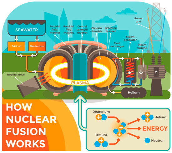
Figure 12.
Schematic representation of thermonuclear fusion. The arrows indicate the directions of the flow of media in the form of sea water and the deuterium and tritium ions produced on its basis, starting from the water reservoir and ending with the fusion reactor. Reproduced with permission from [125], e-magazyny.pl, 2022.
The ITER is set to become the first tokamak to produce more net energy than delivered and that is able to sustain the merger over a long term. It is to demonstrate that it is possible to produce energy from a fusion reaction on a commercial scale. The tokamak has been designed in such a way that, with a supply of 50 MW of power, 500 MW can be obtained from it. It is to be the largest tokamak in the world, using the most powerful electromagnet. The first plasma is to be produced in the reactor in 2025, and regular operation is planned to start in 2035. However, the cost of obtaining energy from fusion reactions is very high. Initially, it was planned that the cost of the ITER project would be around 5 billion USD, and its management is now talking about 22 billion USD. Moreover, the US Department of Energy estimated the total cost at 65 billion USD.
7. Summary
Energy systems in recent times are not sustainable. They are based on the production of energy from non-renewable sources. Much of the power contained in the fuel is irreversibly lost, and energy quality is lowered. Moreover, energy conversion is accompanied by the emission of fossil fuel combustion products into the atmosphere, which pollutes the natural environment. These problems can be solved by using superconducting and plasma technologies. The latter are used, inter alia, to reduce greenhouse gas emissions from internal combustion engines, for air purification and for the transformation and valorization of industrial waste. Gaseous emissions, including sulphurous SO2 and SO3, nitrous compounds NOx, carbon dioxide CO2, ammonia NH3 and VOCs, are becoming more and more restrictive. The conversion of CO2 into other useful products is considered a great challenge. Plasma as a medium used for CO2 conversion has great potential compared to other techniques due to its low temperature operation, the possibility of using renewable energy technology to meet energy needs, the low cost of investment and operation of a reactor and its independence from rare earth materials during its operation. Much development work still needs to be performed before this plasma potential can be fully utilized in practice for the storage and conversion of CO2. One of the major disadvantages is low energy efficiency, especially for barrier dielectric reactors, but the proper selection of the process gas, or its absence and the capture of CO2 directly from the air, can significantly improve conversion efficiency and can ensure high purity of CO. Studies of GAD discharges and microwave MWDs in these applications have shown better energy efficiency. In addition, detailed mechanisms of plasma-induced CO2 desorption and conversion should be investigated. An important and still-studied issue is the development of a high-capacity sorbent for CO2 capturing, to work in a plasma environment. The importance of hydrogen as a fuel of the future and its ability to reduce COx emissions during its production should also be emphasized.
Industrial and municipal waste, including toxic and post-hospital waste, is a serious problem for the natural environment. Regardless of significant progress in this area, there are still technological difficulties that limit the achievement of the expected environmental and economic benefits. High advancement of thermal plasma technology (AD, GAD and MWD) in environmental protection has been recently observed. Research is still being conducted on processes of converting industrial and municipal waste into energy and into liquid and gaseous fuels.
Superconducting technologies in energy and environmental protection use two main phenomena related to superconductivity: (1) zero resistance and (2) perfect diamagnetism, and in a variety of applications, the first group is much wider than the second one. The first group can be divided into DC (various types of electromagnets, winding excitation in electric machines and transmission lines) applications, and the second one can be divided into AC grid applications (transmission lines, transformers, windings of electrical machines and fault current limiters). Superconducting applications using ideal diamagnetism and magnetic field trapping are mainly levitation systems, magnetic bearings, electrical machine excitation systems, magnetic shielding systems and fault current limiters.
Superconducting and plasma technologies are already playing an important role in energy and environmental engineering, and they may play an even greater role in the future. Their potential, combined with renewable energy, results from the possibility of storing energy in the form of hydrogen and other fuels, and in regard to superconductivity in magnetic energy storage devices, they are then used to stabilize the power grid, which indirectly contributes to reducing greenhouse gas emissions, mainly CO2. The huge potential of superconducting technologies also lies in lossless energy transfer and conversion. Applications of superconductors in energy conversion allow one to obtain a significantly higher power density than in conventional devices and an increase in efficiency during energy conversion. Therefore, with respect to energy conversion, superconducting devices have a beneficial effect on the environment due to reductions in power loss.
It seems that, at the present stage of the development of nuclear fusion technology, it is not possible to use it for energy production, because its development consumes more energy than can be obtained from it. However, maintaining the reaction for a long time of several hours generates energy that meets the energy demand in an order of 1015 Wh. The construction costs of tokamaks are also very high, which puts the profitability of their construction into question. These obstacles, along with progressing technological development and the growing demand for clean energy, seem to be overcome, and thermonuclear fusion will become profitable technology in the near future.
Author Contributions
Conceptualization, H.D.S.; methodology, H.D.S. and M.A.S.; software, M.A.S. and O.B.; validation, H.D.S. and M.A.S.; formal analysis, H.D.S., M.A.S. and O.B.; investigation, H.D.S., M.A.S. and O.B.; resources, H.D.S., M.A.S. and O.B.; data curation, O.B.; writing—original draft preparation, H.D.S., M.A.S. and O.B.; writing—review and editing, H.D.S. and M.A.S.; visualization, H.D.S., M.A.S. and O.B.; supervision, H.D.S.; project administration, H.D.S.; funding acquisition, H.D.S. and O.B. All authors have read and agreed to the published version of the manuscript.
Funding
This research, as well as the APC, were funded by the Lublin University of Technology, grant numbers FD 20/EE-2/416 and FD-20/EE-2/401, intended for research activities within the “Automatics, Electronics and Electrical Engineering” scientific discipline.
Institutional Review Board Statement
Not applicable.
Informed Consent Statement
Not applicable.
Data Availability Statement
The data that support the findings of this study are available from the corresponding author upon reasonable request.
Acknowledgments
The inspiration for the article preparation was the project no. PPI_APM_2019_1_00009: “Polish-Japanese Energo-Eco Studies and Expert Visits” funded by the Polish National Agency for Academic Exchange. We also acknowledge fruitful discussion with COST Action CA19108 Hi-Scale management committee members.
Conflicts of Interest
The authors declare no conflict of interest.
References
- Janowski, T.; Stryczewska, H.D.; Wac-Włodarczyk, A. (Eds.) Technologie Nadprzewodnikowe i Plazmowe w Energetyce (Superconducting and Plasma Technologies in the Power Engineering); Lubelskie Towarzystwo Naukowe (Lublin Scientific Society): Lublin, Poland, 2009; ISBN 978-83-61391-76-9. (In Polish) [Google Scholar]
- Jaroszyński, L.; Wojtasiewicz, G.; Janowski, T. Considerations of 2G HTS Transformer Temperature During Short Circuit. IEEE Trans. Appl. Supercond. 2018, 28, 5500205. [Google Scholar] [CrossRef]
- Wang, M.; Zhu, Z.; Ning, F.; Yang, H.; Zhang, G.; Wang, K. Testing of a 5.5 T high-gradient superconducting magnetic separator. J. Supercond. Nov. Magn. 2014, 27, 1397–1401. [Google Scholar] [CrossRef]
- Janowski, T.; Glowacki, B.A.; Wojtasiewicz, G.; Kozak, S.; Kozak, J.; Kondratowicz-Kucewicz, B.; Majka, M.; Wozniak, M. Fault current limitation in power network by the superconducting transformers made of 2G HTS. IEEE Trans. Appl. Supercond. 2011, 21, 1413–1416. [Google Scholar] [CrossRef]
- Kozak, J.; Majka, M.; Kozak, S. Design and development of the first polish superconducting fault current limiter for MV distribution systems. Phys. Procedia 2012, 36, 845–848. [Google Scholar] [CrossRef]
- Cieśla, A. Practical Aspects of High Gradient Magnetic Separation Using Superconducting Magnets. Physicochem. Probl. 2003, 37, 169–181. [Google Scholar]
- Lee, S.W.; Byun, S.B.; Kim, W.S.; Lee, J.K.; Choi, K.D. Design of a single phase 33 MVA HTS transformer with OLTC. IEEE Trans. Appl. Supercond. 2007, 17, 1939–1942. [Google Scholar] [CrossRef]
- Kozak, J.; Janowski, T.; Kozak, S.; Malinowski, H.; Wojtasiewicz, G.; Kondratowicz-Kucewicz, B. Design and testing of 230 V inductive type of Superconducting Fault Current limiter with an open core. IEEE Trans. Appl. Supercond. 2005, 15, 2031–2034. [Google Scholar] [CrossRef]
- Wojtasiewicz, B.; Janowski, T.; Kozak, S.; Kondratowicz-Kucewicz, B.; Kozak, J.; Surdacki, P.; Glowacki, B.A. HTS magnet for 7.3 kJ SMES system. J. Phys. Conf. Ser. 2006, 43, 821–824. [Google Scholar] [CrossRef]
- Grzesik, B.; Janowski, T.; Stepien, M. HTS toroidal helical transformer. J. Phys. Conf. Ser. 2008, 97, 012311. [Google Scholar] [CrossRef]
- Wojtasiewicz, G.; Komarzyniec, G.; Janowski, T.; Kozak, S.; Kozak, J.; Majka, M.; Kondratowicz-Kucewicz, B. Inrush current of superconducting transformer. IEEE Trans. Appl. Supercond. 2013, 23, 5500304. [Google Scholar] [CrossRef]
- Singh, S.; Głuchowska, W.; Neroni, M.; Cure, B.; Dudarev, A.; Mentink, M. CERN North Area Multi-Purpose Superconducting Magnet Facility. IEEE Trans. Appl. Supercond. 2022, 32, 9500105. [Google Scholar] [CrossRef]
- Janowski, T.; Kondratowicz Kucewicz, B.; Wojtasiewicz, G.; Kozak, S.; Kozak, J.; Majka, M.; Jaroszynski, L. Superconducting devices for power engineering. Acta Phys. Pol. A 2016, 130, 537–544. [Google Scholar] [CrossRef]
- Juda, K.L.; Woźniak, M.; Mosiadz, M.; Hopkins, S.C.; Glowacki, B.A.; Janowski, T. Superconducting properties of YBCO coated conductors produced by inkjet printing. Przegląd Elektrotechniczny 2012, 88, 161–163. [Google Scholar]
- Bisht, S.; Nautiyal, B.; Bhatt, U.M.; Joshi, P. Plasma Applications for Environmental Protection. Int. J. Eng. Adv. Technol. 2014, 3, 77–81. [Google Scholar]
- Chen, G.; Godfroid, T.; Britun, N.; Georgieva, V.; Delplancke-Ogletree, M.P.; Snyders, R. Plasma-catalytic conversion of CO2 and CO2/H2O in a surface-wave sustained microwave discharge. Appl. Catal. B Environ. 2017, 214, 114–125. [Google Scholar] [CrossRef]
- Stryczewska, H.D. Plasma Technologies in Energy and Environmental Engineering; Electrotechnical Committee of Polish Academy of Science PAN: Lublin, Poland, 2009; p. 212. ISBN 978-83-7497-070-9. (In Polish) [Google Scholar]
- Penetrante, M.; Schultheis, S.E. (Eds.) Non-Thermal Plasma Techniques for Pollution Control, Part. A: Overview, Fundamentals and Supporting Technologies; NATO ASI Series G: Ecological Science; Springer: Berlin/Heidelberg, Germany, 1993; Volume 34. [Google Scholar]
- Bogaerts, A.; Neyts, E.C. Plasma Technology: An Emerging Technology for Energy Storage. ACS Energy Lett. 2018, 3, 1013–1027. [Google Scholar] [CrossRef]
- Balat, M. Potential importance of hydrogen as a future solution to environmental and transportation problems. Int. J. Hydrog. Energy 2008, 33, 4013–4029. [Google Scholar] [CrossRef]
- Blumberga, A.; Blumberga, D.; Pubule, J.; Romalgori, F. Cost-benefit analysis of plasma-based technologies. In Energy Procedia, Proceedings of the International Scientific Conference Environmental and Climate Technologies–CONECT 2014, Riga, Latvia, 14–16 October 2014; Valtere, S., Ed.; Elsevier Science BV: Amsterdam, The Netherlands, 2015; Volume 72, pp. 170–174. [Google Scholar] [CrossRef]
- Tamošiūnas, A.; Gimžauskaitė, D.; Uscila, R.; Aikas, M. Thermal arc plasma gasification of waste glycerol to syngas. Appl. Energy 2019, 251, 113306. [Google Scholar] [CrossRef]
- Hipler, R.; Kersten, H.; Schmidt, M.; Schoenbach, K.H. (Eds.) Low Temperature Plasmas. Fundamentals, Technologies and Techniques, 2nd ed.; Wiley: Hoboken, NJ, USA, 2008; Volumes 1 and 2, ISBN 978-3-527-40673-9. [Google Scholar]
- Van Laer, K.; Bogaerts, A. Improving the Conversion and Energy Efficiency of Carbon Dioxide Splitting in a Zirconia-Packed Dielectric Barrier Discharge Reactor. Energy Technol. 2015, 3, 1038–1044. [Google Scholar] [CrossRef]
- Ulejczyk, B.; Zbrowska, M.; Bala, D.; Nogal, L.; Mlotek, M.; Krawczyk, K. Hydrogen production from ethanol using dielectric barrier discharge. Energy 2019, 174, 261–268. [Google Scholar] [CrossRef]
- Young, G.C. Municipal Solid Waste to Energy Conversion Processes; John Wiley & Sons Inc.: Hoboken, NJ, USA, 2010; ISBN 978-0-470-53967-5. [Google Scholar]
- Bogack, M.; Pikoń, K. (Eds.) Plazmowe Technologie w Zagospodarowaniu Odpadów Przemysłowych i Komunalnych/Plasma Technologies in the Management of Industrial and Municipal Waste, w Współczesne Problemy Ochrony Środowiska i Energetyki/in Contemporary Problems of Environmental Protection and Energy; MedWin Publishers: Gliwice, Poland, 2020; p. 415. ISBN 978-83-950087-8-8. (In Polish) [Google Scholar]
- Boulos, M.I.; Fauchais, P.; Pfender, E. Thermal Plasma: Fundamental and Applications; Plenum Press: New York, NY, USA, 1994; Volume 1. [Google Scholar]
- 2011–2013 Review of the EU Clean Air Policy. Available online: https://ec.europa.eu/environment/air/clean_air/review.htm (accessed on 24 April 2022).
- Holub, M.; Brandenburg, R.; Grosch, H.; Weinmann, S.; Hansel, B. Plasma supported odour removal from waste air in water treatment plants: An industrial case study. Aerosol Air Qual. Res. 2014, 14, 697–707. [Google Scholar] [CrossRef]
- Stryczewska, H.D.; Ebihara, K.; Muszański, R. Mobile installations of air, water and soil treatment with ozone. In Proceedings of the 23rd International Conference on Advanced Oxidation Technologies for Treatment of Water, Air and Soil-(AOTs-23) 2017, Clearwater Beach, FL, USA, 13–16 November 2017; pp. 43–44. [Google Scholar]
- Pawlat, J.; Stryczewska, H.D.; Ebihara, K.; Mitsugi, F.; Sung, T. AOTs and solar energy for air, water and soil treatment. T MRS Jap. 2014, 39, 117–120. [Google Scholar] [CrossRef][Green Version]
- Abdou, M.; Riva, M.; Ying, A.; Day, C.; Loarte, A.; Baylor, L.R.; Humrickhouse, P.; Fuerst, T.F.; Cho, S. Physics and technology considerations for the deuterium–tritium fuel cycle and conditions for tritium fuel self sufficiency. Nucl. Fusion 2021, 61, 013001. [Google Scholar] [CrossRef]
- International Energy Agency. World Energy Outlook to the Year 2010; IEA: Paris, France, 1993. [Google Scholar]
- United Nations Sustainable Development. UNCED Agenda 21. In Proceedings of the United Nations Conference on Environment and Development, Rio de Janeiro, Brazil, 3–14 June 1992. [Google Scholar]
- Martenson, A. Energy use-for what? In Series of Booklets from The Baltic University Programme: Energy. From Fossil Fuels to Sustainable Energy Resources; Salay, J., Ed.; Lund University: Lund, Sweden, 1996. [Google Scholar]
- Dudley, B. BP Statistical Review of World Energy; BP Statistical Review: London, UK, 2019. [Google Scholar]
- Harrison, R.M. Pollution-Causes, Effects and Control, 3rd ed.; The Royal Society of Chemistry: Cambridge, UK, 1996. [Google Scholar]
- Eren, H. Environmental Impacts of Technology; Webster, J., Ed.; Wiley Encyclopedia of Electrical and Electronics Engineering Online: Hoboken, NJ, USA, 2001. [Google Scholar]
- EU. EU Focus on Clean Air; Publication of European Commission; EU: Brussels, Belgium, 2006. [Google Scholar]
- Stryczewska, H.D. Supply Systems of Non-Thermal Plasma Reactors. Construction Review with Examples of Applications. Appl. Sci. 2020, 10, 3242. [Google Scholar] [CrossRef]
- Sanz, S.; Sarmiento, G.; Pujana, A.; Merino, J.M.; Tropeano, M.; Nardelli, D.; Grasso, G.; Sun, J.; Toral, F.; Marino, I. Experimental Study and Simulation of Quench in MgB2 Coils for Wind Generators. IEEE Trans. Appl. Supercond. 2016, 26, 5201605. [Google Scholar] [CrossRef]
- Huang, Z.; Zhang, M.; Wang, W.; Coombs, T. Trial Test of a Bulk-Type Fully HTS Synchronous Motor. IEEE Trans. Appl. Supercond. 2014, 24, 4602605. [Google Scholar] [CrossRef]
- Yu, H.; Zhang, G.; Jing, L.; Liu, Q.; Yuan, W.; Liu, Z.; Feng, X. Wireless Power Transfer With HTS Transmitting and Relaying Coils. IEEE Trans. Appl. Supercond. 2015, 25, 5000405. [Google Scholar] [CrossRef]
- George, A.; Shen, B.; Craven, M.; Wang, Y.; Kang, D.; Wu, C.; Tu, X. A Review of Non-Thermal Plasma Technology: A novel solution for CO2 conversion and utilization. Renew. Sust. Energ. Rev. 2021, 135, 109702. [Google Scholar] [CrossRef]
- Ojala, S.; Koivikko, N.; Laitinen, T.; Mouammine, A.; Seelam, P.K.; Laassiri, S.; Ainassaari, K.; Brahmiand, R.; Keiski, R.L. Utilization of Volatile Organic Compounds as an Alternative for Destructive Abatement. Catalysts 2015, 5, 1092–1151. [Google Scholar] [CrossRef]
- Czernichowski, A. Gliding Discharge Reactor for H2S Valorization or Destruction. In Non-Thermal Plasma Techniques for Pollution Control, Part. A: Overview, Fundamentals and Supporting Technologies, Proceedings of the NATO Advanced Research Workshop on Non-Thermal Plasma Techniques for Pollution Control, held at Cambridge, UK, 21–25 September 1992; Penetrante, M., Schultheis, S.E., Eds.; NATO ASI Series G: Ecological Science; Springer: Berlin/Heidelberg, Germany, 1992; Volume 34, p. 393. [Google Scholar]
- Ayrault, C.; Barrault, J.; Blin-Simiand, N.; Jorand, F.; Pasquiers, S.; Rousseau, A.; Tatibouët, J. Catalysis Today. In Encyclopedia of Plasma Technology; Shohet, J.L., Ed.; CRC Press Taylor & Francis: Boca Raton, FL, USA, 2004; Volume 89. [Google Scholar]
- Saoud, W.A.; Assadi, A.A.; Guiza, M.; Bouzaza, A.; Aboussaoud, W.; Soutrel, I.; Ouederni, A.; Wolbert, D.; Rtimi, S. Abatement of ammonia and butyraldehyde under non-thermal plasma and photocatalysis: Oxidation processes for the removal of mixture pollutants at pilot scale. Chem. Eng. J. 2018, 344, 165–172. [Google Scholar] [CrossRef]
- Aerts, R.; Somers, W.; Bogaerts, A. Carbon Dioxide Splitting in a Dielectric Barrier Discharge Plasma: A Combined Experimental and Computational Study. Chem. Sus. Chem. 2015, 8, 702–716. [Google Scholar] [CrossRef] [PubMed]
- Sun, S.R.; Wang, H.X.; Mei, D.H.; Tu, X.; Bogaerts, A. CO2 conversion in a gliding arc plasma: Performance improvement based on chemical reaction modeling. J. CO2 Util. 2017, 17, 220–234. [Google Scholar] [CrossRef]
- de la Fuente, J.F.; Moreno, S.H.; Stankiewicz, A.I.; Stefanidis, G.D. On the improvement of chemical conversion in a surface-wave microwave plasma reactor for CO2 reduction with hydrogen (The Reverse Water-Gas Shift reaction). Int. J. Hydrog. Energy 2017, 42, 12943–12955. [Google Scholar] [CrossRef]
- Jamroz, P.; Kordylewski, W.; Wnukowski, M. Microwave plasma application in decomposition and steam reforming of model tar compounds. Fuel Process. Technol. 2018, 169, 1–14. [Google Scholar] [CrossRef]
- Bień, J.B.; Sobik-Szołtysek, J.; Wystalska, K.; Kowalczyk, M.; Kamizela, T. Unieszkodliwianie Osadów Przemysłowych/Industrial sludge Neutralization; Wydawnictwo Politechniki Częstochowskiej: Częstochowa, Poland, 2019; ISBN 628.4.038:628.3.034.2. (In Polish) [Google Scholar]
- Jiang, Z.; Xiao, T.; Kuznetsov, V.L.; Edwards, P.P. Turning carbon dioxide into fuel. Trans. A Math. Phys. Eng. Sci. 2010, 368, 3343–3364. [Google Scholar] [CrossRef] [PubMed]
- Silva, T.; Britun, N.; Godfroid, T.H.; Snyders, R. Understanding CO2 decomposition in microwave plasma by means of optical diagnostics. Plasma Process Polym. 2017, 14, e1600103. [Google Scholar] [CrossRef]
- Bogaerts, A.; Centi, G. Plasma Technology for CO2 Conversion: A Personal Perspective on Prospects and Gaps. Front. Energy Res. 2020, 8, 111. [Google Scholar] [CrossRef]
- Belov, I.; Vermeiren, V.; Paulussen, S.; Bogaerts, A. Carbon dioxide dissociation in a microwave plasma reactor operating in a wide pressure range and different gas inlet configurations. J. CO2 Util. 2018, 24, 386–397. [Google Scholar] [CrossRef]
- Nunnally, T.; Gutsol, K.; Rabinovich, A.; Fridman, A.; Gutsol, A.; Kemoun, A. Dissociation of CO2 in a low current gliding arc plasmatron. J. Phys. D Appl. Phys. 2011, 44, 274009. [Google Scholar] [CrossRef]
- Britun, N.; Silva, T.; Chen, G.X.; Godfroid, T.; van der Mullen, J.; Snyders, R. Plasma-assisted CO2 conversion: Optimizing performance via microwave power modulation. J. Phys. D Appl. Phys. 2018, 51, 4002. [Google Scholar] [CrossRef]
- Chronopoulos, T.; Fernandez-Diez, Y.; Maroto-Valer, M.M.; Ocone, R.; Reay, D.A. CO2 desorption via microwave heating for post-combustion carbon capture. Micropor. Mesopor. Mat. 2014, 197, 288–290. [Google Scholar] [CrossRef]
- Fernández, J.; Sotenko, M.; Derevschikov, V.; Lysikov, A.; Rebrov, E.V. A radiofrequency heated reactor system for post-combustion carbon capture. Chem. Eng. Process. Process Intensif. 2016, 108, 17–26. [Google Scholar] [CrossRef]
- Sabogal, S.O.; Valina, S.; Thiery, S.; Salvador, S. Design and thermal characterization of an induction-heated reactor for pyrolysis of solid waste. Chem. Eng. Res. Des. 2021, 173, 206–214. [Google Scholar] [CrossRef]
- Li, S.R.; Ongis, M.; Manzolin, G.; Gallucci, F. Non-thermal plasma-assisted capture and conversion of CO2. Chem. Eng. J. 2021, 410, 128335. [Google Scholar] [CrossRef]
- Goede, A.; van de Sanden, M.C.M. CO2-Neutral Fuels. Europhys. News 2016, 47, 22–26. [Google Scholar] [CrossRef]
- Lackner, K. Capture of carbon dioxide from ambient air. Eur. Phys. J. Spec. Top. 2009, 176, 93–106. [Google Scholar] [CrossRef]
- Supasitmongkol, S.; Styring, P. A single centre aluminium(iii) catalyst and TBAB as an ionic organo-catalyst for the homogeneous catalytic synthesis of styrene carbonate. Catal. Sci. Technol. 2014, 4, 1622–1630. [Google Scholar] [CrossRef]
- Diomede, P.; van de Sanden, M.C.M.; Longo, S. Insight into CO2 Dissociation in Plasma from Numerical Solution of a Vibrational Diffusion Equation. J. Phys. Chem. A 2017, 121, 19568–19576. [Google Scholar] [CrossRef]
- Diomede, P.; van de Sanden, M.C.M.; Longo, S. Vibrational Kinetics in Plasma as a Functional Problem: A Flux-Matching Approach. J. Phys. Chem. A 2018, 122, 7918–7923. [Google Scholar] [CrossRef]
- Veerapandian, S.K.P.; Leys, C.; De Geyter, N.; Morent, R. Abatement of VOCs Using Packed Bed Non-Thermal Plasma Reactors: A Review. Catalysts 2017, 7, 113. [Google Scholar] [CrossRef]
- Chmielewski, A.G.; Zwolinska, E.A.; Sun, Y. Electron beam flue gas technology for SOx and NOx simultaneous removal-process and its chemistry evolution from power plants to diesel off gases treatment. Rev. Chem. Eng. 2019, 36, 933–945. [Google Scholar] [CrossRef]
- Pawłat, J.; Diatczyk, J.; Stryczewska, H. Low-temperature plasma for exhaust gas purification from paint shop-a case study. Przegląd Elektrotechniczny 2011, 87, 245–248. [Google Scholar]
- United Nations. Gothenburg Protocol, ECE/EB.AIR/149; United Nations: New York, NY, USA, April 2021. [Google Scholar]
- Holub, M.; Kalisiak, S.; Borkowski, T.; Myskow, J.; Brandenburg, R. The Influence of Direct Non-Thermal Plasma Treatment on Particulate Matter (PM) and NOx in the Exhaust of Marine Diesel Engines. Pol. J. Environ. Stud. 2010, 19, 1199–1211. [Google Scholar]
- Babaie, M.; Kishi, T.; Arai, M.; Zama, Y.; Furuhata, T.; Ristovski, Z.; Rahimzadeh, H.; Brown, R.J. Influence of non-thermal plasma after-treatment technology on diesel engine particulate matter composition and NOx concentration. Int. J. Environ. Sci. Technol. 2016, 13, 221–230. [Google Scholar] [CrossRef]
- Guo, X.R.; Ha, K.H.; Du, D.F. Atmospheric Pressure Plasma for Diesel Particulate Matter Treatment: A Review. Catalysts 2021, 11, 29. [Google Scholar] [CrossRef]
- Allamsetty, S.; Madhukar, A. Review of Discharge Plasma Treatment of NOX in Diesel Engine Exhaust: Progress in Stand-Alone and Cascaded Measures. IEEE Trans. Plasma Sci. 2021, 49, 1510–1526. [Google Scholar] [CrossRef]
- Yao, S.; Zhang, H.; Shen, X.; Han, J.; Wu, Z.; Tang, X.; Lu, H.; Jiang, B.; Nozaki, T.; Zhang, X. A Novel Four-Way Plasma-Catalytic Approach for The Aftertreatment of Diesel Engine Exhausts. Ind. Eng. Chem. Res. 2018, 57, 1159–1168. [Google Scholar] [CrossRef]
- Zheng, Y.; Luss, D.; Harold, M.P. Optimization of LNT-SCR Dual-Layer Catalysts for Diesel NOx Emission Control. SAE Int. J. Engines 2014, 7, 1280–1289. [Google Scholar] [CrossRef]
- Wade, J.; Farrauto, R.J. Controlling emissions of pollutants in urban areas. In Metropolitan Sustainability: Understanding and Improving the Urban Environment; Zeman, F., Ed.; Woodhead Publishing: Cambridge, UK; Philadelphia, PA, USA, 2012; pp. 260–291. [Google Scholar] [CrossRef]
- Liu, Z.; Ge, Y.; Tan, J.; He, C.; Shah, A.N.; Ding, Y.; Yu, L.; Zhao, W. Impacts of continuously regenerating trap and particle oxidation catalyst on the NO2 and particulate matter emissions emitted from diesel engine. J. Environ. Sci. 2012, 24, 624–631. [Google Scholar] [CrossRef]
- Guan, C.; Li, X.; Liao, B.; Huang, Z. Effects of fuel injection strategies on emissions characteristics of a diesel engine equipped with a particle oxidation catalyst (POC). J. Environ. Chem. Eng. 2016, 4, 4822–4829. [Google Scholar] [CrossRef]
- Vinh, T.Q.; Watanabe, S.; Furuhata, T.; Arai, M. Effects of particulate matter on NOx removal in dielectric barrier discharges. J. Energy Inst. 2012, 85, 163–169. [Google Scholar] [CrossRef]
- Aubin, D.G.; Abbatt, J.P.D. Interaction of NO2 with Hydrocarbon Soot: Focus on HONO Yield, Surface Modification, and Mechanism. J. Phys. Chem. A 2007, 111, 6263–6273. [Google Scholar] [CrossRef] [PubMed]
- Takaki, K.; Hatanaka, Y.; Arima, K.; Mukaigawa, S.; Fujiwara, T. Influence of electrode configuration on ozone synthesis and microdischarge property in dielectric barrier discharge reactor. Vacuum 2008, 83, 128–132. [Google Scholar] [CrossRef]
- Mohapatro, S.; Rajanikanth, B.S. A core study on NOx removal in diesel exhaust by pulsed/AC/DC electric discharge plasma. In Proceedings of the IEEE 2011 International Conference on Power and Energy Systems (ICPS), Chennai, India, 22–24 December 2011; IEEE Explore Digital Library: New York, NY, USA, 2011; pp. 1–6. [Google Scholar] [CrossRef]
- Srinivasan, A.D.; Rajnikanth, B.S.; Mohapatro, S. Corona treatment for NOx reduction from stationary diesel engine exhaust impact of nature of energization and exhaust composition. In Proceedings of the Electrostatics Joint Conference, Boston, MA, USA, 16–18 June 2009; p. 44150. [Google Scholar]
- Bhattacharyya, A.; Rajanikanth, B.S. Performance of helical and straight-wire corona electrodes for NOx abatement under AC/pulse energizations. Int. J. Plasma Environ. Sci. Technol. 2013, 7, 148–156. [Google Scholar]
- Song, C.L.; Bin, F.; Tao, Z.M.; Li, F.C.; Huang, Q.F. Simultaneous removals of NOx, HC and PM from diesel exhaust emissions by dielectric barrier discharges. J Hazard Mater. 2009, 166, 523–530. [Google Scholar] [CrossRef] [PubMed]
- Wedaa, H.; Abdel-Salam, M.; Ahmed, A.; Mizuno, A. NO removal using dielectric barrier discharges in a multirod reactor stressed by AC and pulsed high voltages. IEEE Trans. Dielectr. Electr. Insul. 2011, 18, 1743–1751. [Google Scholar] [CrossRef]
- Yankelevich, Y.; Wolf, M.; Baksht, R.; Pokryvailo, A.; Vinogradov, J.; Rivin, B.; Sher, E. NOx diesel exhaust treatment using a pulsed corona discharge: The pulse repetition rate effect. Plasma Sources Sci. Technol. 2007, 16, 386–391. [Google Scholar] [CrossRef]
- Matsumoto, T.; Wang, D.; Namihira, T.; Akiyama, H. Performances of 2 nanoseconds pulsed discharge plasma. Jpn. J. Appl. Phys. 2011, 50, 08JF14. [Google Scholar] [CrossRef]
- Mohapatro, S.; Allamsetty, S.; Madhukar, A.; Sharma, N.K. Nanosecond pulse discharge based nitrogen oxides treatment using different electrode configurations. High Voltage 2017, 2, 60–68. [Google Scholar] [CrossRef]
- Osawa, N.; Suetomi, T.; Hafuka, Y.; Tsuha, K.; Yoshioka, Y.; Hanaoka, R. Investigation on reactor configuration of nonthermal plasma catalytic hybrid method for NOx removal of diesel engine exhaust. Int. J. Plasma Environ. Sci. Technol. 2012, 6, 119–124. [Google Scholar]
- Borkowski, T.; Myśków, J.; Kalisiak, S.; Hołub, M. Non-Thermal Plasma Reactor Use In Marine Diesel Engine Exhaust System. J. KONES 2008, 15, 37–44. [Google Scholar]
- Chmielewski, G.; Sun, Y.; Zwolińska, E.; Pawelec, A. Możliwości zmniejszenia stężeń SO2 i NOx w gazach odlotowych emitowanych z okrętowych silników Diesla. Przemysł Chem. 2019, 98, 56–63. (In Polish) [Google Scholar] [CrossRef]
- Balachandran, W.; Manivannan, N.; Beleca, R.; Abbod, M.F.; Brennen, D.; Alozie, N.S.; Ganippa, L.C. Nonthermal Plasma System for Marine Diesel Engine Emission Control. IEEE Trans. Ind. Appl. 2016, 52, 2496–2505. [Google Scholar] [CrossRef]
- Kuwahara, T.; Yoshida, K.; Hanamoto, K.; Hanamoto, K.; Sato, K.; Kuroki, T.; Okubo, M. A Pilot-Scale Experiment for Total Marine Diesel Emission Control Using Ozone Injection and Nonthermal Plasma Reduction. IEEE Trans. Ind. Appl. 2015, 51, 1168. [Google Scholar] [CrossRef]
- Kuwahara, T.; Yoshida, K.; Kuroki, T.; Hanamoto, K.; Hanamoto, K.; Sato, K.; Okubo, M. Pilot-Scale Aftertreatment Using Nonthermal Plasma Reduction of Adsorbed NOx in Marine Diesel-Engine Exhaust Gas. Plasma Chem. Plasma Process. 2014, 34, 65–81. [Google Scholar] [CrossRef]
- Holub, M.; Joegi, I.; Stamate, E.; Irimiea, C.; Schmidt, M.; Brandenburg, R.; Bonislawski, M.; Jakubowski, T.; Kaariainen, M.L.; Cameron, D. Comparison of direct and indirect plasma oxidation of NO combined with oxidation by catalyst. Fuel 2015, 144, 137–144. [Google Scholar] [CrossRef]
- Jogi, I.; Erme, K.; Haljaste, A.; Laan, M. Oxidation of nitrogen oxide in hybrid plasma-catalytic reactors based on DBD and Fe2O3. Eur. Phys. J. Appl. Phys. 2013, 61, 24305-p5. [Google Scholar] [CrossRef]
- Skalska, K.; Miller, J.S.; Wilk, M.; Ledakowicz, S. Nitrogen oxides ozonation as a method for NOx emission abatement. Ozone Sci. Eng. 2012, 34, 252–258. [Google Scholar] [CrossRef]
- Wiltsche, H.; Moradi, F.; Tirk, P.; Knapp, G. Online combustion followed by carbon dioxide removal: Evaluation of a new approach for the analysis of volatile organic substances by inductively coupled plasma optical emission spectrometry. J. Anal. At. Spectrom. 2014, 29, 1767–1777. [Google Scholar] [CrossRef][Green Version]
- Ganguly, R.K.; Chakraborty, S.K. Integrated approach in municipal solid waste management in COVID-19 pandemic: Perspectives of a developing country like India in a global scenario. Case Stud. Chem. Environ. Eng. 2021, 3, 100087. [Google Scholar] [CrossRef]
- Miotk, R.; Hrycak, B.; Czylkowski, D.; Jasinski, M.; Dors, M.; Mizeraczyk, J. Liquid fuel reforming using microwave plasma at atmospheric pressure. In Proceedings of the 32nd ICPIG, Iași, Romania, 26–31 July 2015. [Google Scholar]
- Mlotek, M.; Woroszyl, J.; Ulejczyk, B.; Krawczyk, K. Coupled Plasma-Catalytic System with Rang 19pr Catalyst for Conversion of Tar. Sci. Rep. 2019, 9, 13562. [Google Scholar] [CrossRef] [PubMed]
- Colle, A.; Lubin, T.; Ayat, S.; Gosselin, O.; Leveque, J. Test of a Flux Modulation Superconducting Machine for Aircraft. J. Phys. Conf. Ser. 2020, 1590, 012052. [Google Scholar] [CrossRef]
- Lasek, P.; Habelok, K.; Stepien, M. Armature winding analysis for high-temperature superconducting PM-excited AC machines. Int. J. Appl. Electromagn. Mech. 2020, 64, S269–S278. [Google Scholar] [CrossRef]
- Abrahamsen, A.; Mijatovic, N.; Seiler, E.; Zirngibl, T.; Traeholt, C.; Norgard, P.B.; Pedersen, N.F.; Andersen, N.H.; Ostergard, J. Superconducting wind turbine generators. Supercond. Sci. Technol. 2010, 23, 034019. [Google Scholar] [CrossRef]
- Kolchanova, I.; Poltavets, V. Superconducting generators for wind turbines. In Proceedings of the 2021 International Conference on Electrotechnical Complexes and Systems (ICOECS), Ufa, Russia, 26–29 October 2021. [Google Scholar] [CrossRef]
- Fair, R.; Lewis, C.; Eugene, J.; Ingles, M. Development of an HTS hydroelectric power generator for the hirschaid power station. J. Phys. Conf. Ser. 2009, 234, 032008. [Google Scholar] [CrossRef]
- Kalsi, S.; Gamble, B.; Snitchler, G.; Ige, S. The Status of HTS Ship Propulsion Motor Developments. In Proceedings of the 2006 IEEE Power Engineering Society General Meeting, Montreal, QC, Canada, 18–22 June 2006. [Google Scholar] [CrossRef]
- Gamble, B.; Snitchler, G.; MacDonald, T. Full Power Test of a 36.5 MW HTS Propulsion Motor. IEEE Trans. Appl. Supercond. 2011, 21, 1083–1088. [Google Scholar] [CrossRef]
- Zheng, J.; Peng, S.; Li, W.; Dai, Y. Magnet design of 10MJ multiple solenoids SMES. IOP Conf. Ser. Earth Environ. Sci. 2019, 233, 032026. [Google Scholar] [CrossRef]
- Pasko, S.; Biskup, T.; Buehrer, C.; Grzesik, B.; Roest-Krijgsman, J.; Michalak, J.; Stepien, M.; Zygmanowski, M. Comparison of SMES and ScES based power conditioning systems. In Proceedings of the 2005 European Conference on Power Electronics and Applications, Dresden, Germany, 11–14 September 2005. [Google Scholar] [CrossRef]
- Strasik, M.; Johnson, P.E.; Day, A.C.; Mittleider, J.; Higgins, M.D.; Edwards, J.; Schindler, J.R.; McCrary, K.E.; McIver, C.R.; Carlson, D.; et al. Design, Fabrication, and Test of a 5-kWh/100-kW Flywheel Energy Storage Utilizing a High-Temperature Superconducting Bearing. IEEE Trans. Appl. Supercond. 2007, 17, 2133–2137. [Google Scholar] [CrossRef]
- Runde, M.; Magnusson, N.; Fulbier, C.; Buhrer, C. Commercial Induction Heaters With High-Temperature Superconductor Coils. IEEE Trans. Appl. Supercond. 2011, 21, 1379–1383. [Google Scholar] [CrossRef]
- Stemmle, M.; Merschel, F.; Noe, M.; Hobl, A. AmpaCity—Advanced superconducting medium voltage system for urban area power supply. In Proceedings of the 2014 IEEE PES T&D Conference and Exposition, Chicago, IL, USA, 14–17 April 2014. [Google Scholar] [CrossRef]
- Soika, R.; Granados, X.; Cascante, S. ENDESA Supercable, a 3.2 kA, 138 MVA, Medium Voltage Superconducting Power Cable. IEEE Trans. Appl. Supercond. 2011, 21, 972–975. [Google Scholar] [CrossRef]
- Jin, J.; Chen, X. Development of HTS transformers. In Proceedings of the 2008 IEEE International Conference on Industrial Technology, Chengdu, China, 21–24 April 2008. [Google Scholar] [CrossRef]
- Moriconi, F.; De La Rosa, F.; Darmann, F.; Nelson, A.; Masur, L. Development and Deployment of Saturated Core Fault Current Limiters in Distribution and Transmission Substations. IEEE/CSC ESAS Eur. Supercond. News Forum (ESNF) 2010, 21, 1288–1293. [Google Scholar] [CrossRef]
- Pei, X.; Smith, A.; Barnes, M. Superconducting Fault Current Limiters for HVDC Systems. In Proceedings of the 12th Deep Sea Offshore Wind R&D Conference, EERA DeepWind 2015, Trondheim, Norway, 4–6 February 2015. [Google Scholar] [CrossRef]
- Krosny, S.; Wozniak, M.; Hopkins, S.C.; Stepien, M.; Grzesik, B.; Glowacki, B.A. Modeling of transient state phenomena of composite superconducting conductors during pulse Ic(B) measurements. J. Phys. Conf. Ser. 2010, 234, 022019. [Google Scholar] [CrossRef]
- Janowski, T.; Wojtasiewicz, G. Possibility of Using the 2G HTS Superconducting Transformer to Limit Short-Circuit Currents in Power Network. IEEE Trans. Appl. Supercond. 2010, 22, 5500804. [Google Scholar] [CrossRef]
- Fuzja Jądrowa–źródło Energii Przyszłości?-Magazyny Energii/Nuclear Fusion-The Energy of the Future?-Energy Storage. Available online: https://e-magazyny.pl/zielone-wiadomosci/fuzja-jadrowa-zrodlo-energii-przyszlosci/ (accessed on 25 April 2022).
- Surdacki, P. A fusion reactor as an energy source using plasma and superconducting technologies/Reaktor termojądrowy jako źródło energii wykorzystujące technologie plazmowe i nadprzewodnikowe. In Unconventional Energy and Waste Management: Monograph/Energia Niekonwencjonalna i Zagospodarowanie Odpadów: Monografia; Wiatr, I., Marczak, H., Eds.; Lublin Scientific Society/Lubelskie Towarzystwo Naukowe: Lublin, Poland, 2010; ISBN 978-83-62025-06-0. (In Polish) [Google Scholar]
- Peart, B.; Dolder, K.T. Measurements of cross sections for the dissociative recombination of D2+ ions. J. Phys. B Atom. Mol. Phys. 1973, 6, L359. [Google Scholar] [CrossRef]
- Larsson, M.; Orel, A.E. Dissociative Recombination of Molecular Ions, 1st ed.; Cambridge University Press: Cambridge, UK, 2008; p. 201. [Google Scholar]
- Bacal, M.; Sasao, M.; Wada, M. Negative ion sources. J. Appl. Phys. 2021, 129, 221101. [Google Scholar] [CrossRef]
- Cavenago, M.; Kulevoy, T.; Petrenko, S.; Serianni, G.; Antoni, V.; Bigi, M.; Fellin, F.; Recchia, M.; Veltri, P. Development of a versatile multiaperture negative ion source. Rev. Sci. Instrum. 2012, 83, 02A707. [Google Scholar] [CrossRef]
- Belchenko, Y.I.; Dimov, G.I.; Dudnikov, V.G. A powerful injector of neutrals with a surface-plasma source of negative ions. Nucl. Fusion 1974, 14, 113–114. [Google Scholar] [CrossRef]
- Bacal, M.; Truc, A.; Doucet, H.J.; Lamain, H.; Chrétien, M. Charge-exchange cell with cesium recycling. Nucl. Instrum. Methods 1974, 114, 407–409. [Google Scholar] [CrossRef]
- Moehs, D.P.; Peters, J.; Sherman, J. Negative hydrogen ion sources for accelerators. IEEE Trans. Plasma Sci. 2005, 33, 1786–1798. [Google Scholar] [CrossRef]
- Bacal, M. Photodetachment diagnostic techniques for measuring negative ion densities and temperatures in plasmas. Rev. Sci. Instrum. 2000, 71, 3981–4006. [Google Scholar] [CrossRef]
- Leung, K.N.; Bacal, M. H− ion density-measurement in a tandem multicusp discharge. Rev. Sci. Instrum. 1984, 55, 338–341. [Google Scholar] [CrossRef]
- Okumura, Y.; Hanada, M.; Inoue, T.; Kojima, H.; Matsuda, Y.; Ohara, Y.; Seki, M.; Watanabe, K. Cesium mixing in the multi-ampere volume H− ion source. AIP Conf. Proc. 1990, 210, 169–183. [Google Scholar] [CrossRef]
- Sarmento, T.; Stockli, M.; Welton, R.; Han, B.; Murray, S.; Pennisi, T.; Stinson, C.; Tarvainen, O.; Lawrie, S.; Faircloth, D. A comparison of SNS internal and external antenna source performance with and without cesium. Rev. Sci. Instrum. 2020, 91, 023319. [Google Scholar] [CrossRef] [PubMed]


Publisher’s Note: MDPI stays neutral with regard to jurisdictional claims in published maps and institutional affiliations. |
© 2022 by the authors. Licensee MDPI, Basel, Switzerland. This article is an open access article distributed under the terms and conditions of the Creative Commons Attribution (CC BY) license (https://creativecommons.org/licenses/by/4.0/).