Article

Performance Evaluation of PVT Air Collector Coupled with a Triangular Block in Actual Climate Conditions in Korea

1
Pukyong National University Industry-University Cooperation Foundation, Pukyong National University, Busan 48513, Korea
2
Department of Refrigeration and Air-Conditioning Engineering, Pukyong National University, Busan 48513, Korea
*
Author to whom correspondence should be addressed.
Energies 2022, 15(11), 4150; https://doi.org/10.3390/en15114150
Submission received: 9 May 2022 / Revised: 2 June 2022 / Accepted: 4 June 2022 / Published: 5 June 2022
(This article belongs to the Topic Solar Thermal Energy and Photovoltaic Systems)

Abstract

:
This study experimentally investigated the performance of a PVT air collector coupled with a triangular block. The triangular block, newly suggested by the authors, is a triangular-shaped obstacle and was inserted at the bottom of the PVT air collector to enhance the heat transfer performance of the collector. The experiment was carried out in actual climate conditions in Korea with two air mass flow rate conditions: 0.03606 kg/m2 s and 0.06948 kg/m2 s. Results show the average values of electrical efficiency of the collector during the test period to be 16.15% and 16.43% for each air mass flow rate, while thermal efficiencies were 28.83% and 38.36%, respectively. The average values of total energy efficiencies were found to be 44.99% and 54.79%, respectively. The results show that air mass flow rate has a large impact on thermal and total energy efficiency, while it has a small impact on electrical efficiency. Furthermore, it was confirmed that the PVT air collector coupled with a triangular block can enhance the utilization of solar energy since the thermal performance was higher than that of the collector without a triangular block.

1. Introduction

The PV module is one of the most frequently utilized renewable energy products in the world to convert solar energy into useful energy. It can directly change incident solar radiation into electrical power. However, only around 12–18% of solar radiation turns into useful electrical energy during the operation of the PV module [1]. Much solar irradiance captured by a PV module is reflected or changed into thermal energy that leads to high increases in the temperature of the PV module. As the temperature of the PV module rises, the electrical efficiency of the PV module decreases. In contrast to this, by decreasing the temperature of the PV module, its electrical efficiency can be enhanced [2,3,4].
To maintain the lower temperature of the PV module, the first concept of the PVT collector was suggested by Wolf [5]. The PVT collector is a hybrid system that was composed of a PV module and an active cooling system, such as a liquid pipe, air duct, etc. The active cooling system retrieves thermal energy from the PV module. Therefore, by reducing the PV module temperature, a decrease in its electrical efficiency can be prevented. Also, cooling mediums heated by PV modules can be utilized to generate useful thermal energy for drying crops and fruits, space heating, providing hot water supply, and so on [6,7,8].
Generally, liquid-cooling and air-cooling methods are utilized to reduce the temperature of the PV module. The liquid-type PVT collector usually uses water or nanofluid to cool the PV module. Nualboonrueng et al. conducted a performance evaluation of a liquid-type PVT solar collector to confirm the feasibility for residential application in an outdoor field in Bangkok [9]. Exergy and economic investigations for a commercialized PVT water collector were performed by Jahromi et al. using known price and technical parameters for different climates in Iran; their the results showed that a PVT water collector with specified economic parameters is marginally economically feasible [10]. Motamedi et al. carried out a comparative study on the performance characteristics of a liquid-type PVT collector, which had hydrophobic microchannels, with and without nanofluid. From the results, it was confirmed that the thermal performance of the collector using selective Ag/SiO2 core-shell nanofluid can be improved by 20% compared with the collector using water [11]. Lee et al. examined the thermal and electrical characteristics of a liquid-type PVT collector using nanofluid and found that the PVT system using Al2O3/water nanofluid had a 15.14% higher thermal efficiency than that of the system using water [12]. The performance of an unglazed PVT water collector was investigated experimentally by Calise et al., who utilized a one-dimensional finite-volume model to confirm the impact of the different operating conditions. In their research, it was observed that the thermal and electrical performances increased with an increment of the solar intensity and decreased with an increment of the fluid inlet temperature [13]. Liu et al. proposed equivalent overall output energy to evaluate energy performance and optimize a hybrid system composed of a PVT water collector integrated with aPCM (phase change material) and a phase change material-ventilated trombe wall [14]. Sarafraz et al. assessed the electrical and thermal characteristics of a liquid-type PVT collector; their results confirmed that combining a PVT collector with a cooling jacket packed with PCM boosted the system’s thermal and electrical generation by 130% and 20%, respectively [15].
The liquid-type PVT collector generally has a higher thermal performance than that of an air-type PVT collector because of the higher thermal conductivity of the liquid [16]. However, the liquid-type PVT collector is more expensive due to its relatively complex design and because it takes up more space. Also, the liquid-type PVT collector is difficult to install compared with the air-type PVT collector. Meanwhile, the air-type PVT collector has a simple design. In addition to this, it is economic and requires a little maintenance; however, due to the low thermal conductivity and capacity of air, this collector has a lower thermal efficiency than a liquid-type PVT collector, as stated previously [17,18]. Hence, much research has been undertaken in an attempt to promote the thermal performance of the PVT air collector.
Sopian et al. conducted a comparison study on the thermal and electrical behaviors of single and double-pass PVT air collectors using mathematical models based on energy conservation. In this research, they found that the PVT air collector with a double-pass air channel could generate much more electricity and heat than a single-pass type collector [19]. Othman et al. studied the electrical and thermal characteristics of the double-pass PVT air collector combined with fins by using a mathematical model and confirmed that utilizing a double-pass air channel and fins improved the electrical and thermal efficiency of the collector [20]. Jin et al. examined the performance of a PVT air collector having a single-pass air channel and rectangular tunnel absorber under the PV module in a laboratory using halogen lamps as a solar simulator. They found that the rectangular tunnel absorber enhanced both the thermal and electrical efficiencies of the collector [21]. To provide uniform air flow in an air channel of the collector, Teo et al. designed a parallel array of ducts having inlet and outlet manifolds. The results demonstrated that the collector’s electrical efficiency using a newly designed air duct to actively cool the PV module was in the range of 12–14%, while the collector without active cooling only achieved an electrical efficiency of 8–9% [22]. Hussain et al. suggested combining a PVT air collector with a hexagonal honeycomb heat exchanger to improve thermal performance, and the electrical and thermal performances of the collector combined with a proposed heat exchanger were enhanced by 0.1% and 60%, respectively, over the collector without a heat exchanger [23]. Fan et al. conducted optimization of the finned PVT air collector using the Taguchi method. As a result, it was found that the final determined optimal design could improve both net power generation and thermal output by 20% and 21.9% [24]. Kim et al. suggested a newly designed air-type PVT collector, which has bending round-shaped heat-absorbing plates and experimentally investigated the electrical and thermal characteristics. In this study, it was observed that thermal and electrical efficiencies improved as the air mass flow rate was raised [1]. Choi et al. suggested a PVT air collector that employed a non-uniform transverse rib and double-flow air channel. In this research, the proposed collector’s minimum and maximum overall energy efficiencies were found to be 46.24% and 75.3% according to the experimental conditions investigated [25]. The performance of a heat-recovery ventilator combined with an air-type PVT collector was studied by Kim et al., and their results showed that the air-type PVT collector could reduce the energy required for heating in a building by 10% [26]. Yu et al. conducted CFD (computational fluid dynamics) analysis to confirm the uniformity of the air flow in a building-integrated PVT air collector. Their results confirmed that the thermal efficiency of the collector could be improved by 20% according to air distribution methods [27]. In addition to these studies, other previous research has been conducted to enhance the heat transfer performance of the PVT air collector [28,29,30,31].
In this study, the performance of a PVT air collector coupled with a triangular block, and newly proposed and designed by the authors, is evaluated in the actual climate conditions in Korea in November. November is a cold month in Korea. The triangular block was attached at the bottom plate, and it enhanced the heat transfer performance by inducing an increase in local velocity of air in an air channel. This is different to previously studied heat transfer enhancement devices, such as fins and rectangular tunnels, used to extend the heat transfer area. The triangular block also has merits in manufacturing and cost because of its simple design [32]. The electrical and thermal performances are investigated with the two different air mass flow rates on two different days with similar weather conditions. The main aims of this research were as follows: (a) to evaluate the electrical and thermal performances of the PVT collector coupled with a triangular block under actual climate conditions in Korea; (b) to assess the impact of air mass flow rate on the thermal and electrical performance; and (c) to confirm the feasibility of the suggested PVT air collector.

2. Experimental Apparatus and Methods

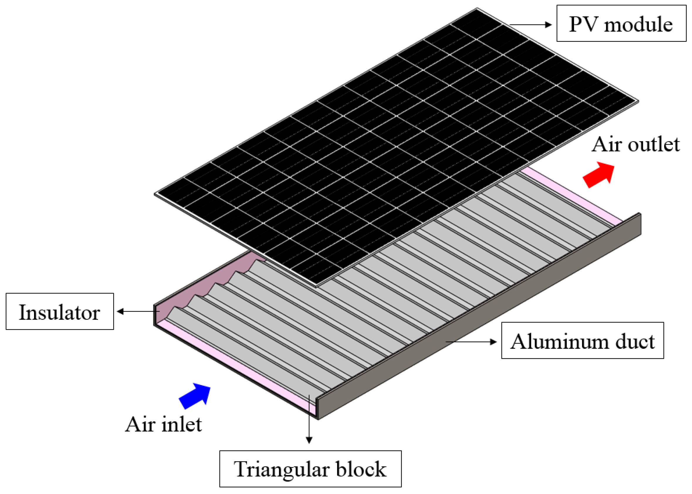
2.1. PVT Air Collector Coupled with a Triangular Block

The PVT air collector consists of a commercially available PV module (LG360S2W-5K) and an air duct having a triangular block. Table 1 summarizes the parameters of the PV module used to fabricate the PVT air collector. The parameters obtained under standard conditions.
An air duct of 1030 mm width, 100 mm height, and 2027 mm length was used to fabricate the PVT air collector. A total of 15 triangular blocks of 1000 mm width, 37 mm height, 97 mm length, and 126.5 mm pitch were attached at the bottom of the air duct to promote the collector’s thermal performance. The triangular block, which was suggested and designed by the authors, is a triangular-shaped obstacle made by folding an aluminum plate.
Figure 1 and Figure 2 present the composition and side view of the PVT air collector coupled with the triangular block. In Figure 3, an actual view of a triangular block in an air duct of a PVT air collector is shown and more detailed dimensions of the air duct and triangular block are summarized in Table 2.

2.2. Experimental Setup and Methods

The actual view and schematic of the experimental setup for the PVT air collector are shown in Figure 4. Generally, solar intensity reaches the maximum value at about 12:00. Hence, the experiments for performance evaluation of the collector were carried out from 10:00 to 14:00 to include the maximum value of the solar intensity. The experiments were performed with two different air mass flow rates, 0.03606 kg/m2 s and 0.06948 kg/m2 s, on two different days to take the effect of air mass flow rate into consideration. All the experiments were conducted in the actual climate conditions in Korea in November. The experimental setup was located at Engineering Building 2, Pukyong National University.
The measured values to analyze the collector’s performance were solar intensity, voltage of the PV module, ampere of the PV module, outlet air temperature of the collector, outlet air velocity of the collector, and ambient air temperature. The pyranometer was used to measure solar intensity. A DC voltage meter and a DC ampere meter were used to obtain the voltage and ampere produced from the PV cell. The outlet air temperatures of the collector and ambient air temperature were measured by thermocouples. An anemometer was used to measure air velocity. Air mass flow rate is defined as the product of air density, cross-section area of the air duct, and air velocity. Thus, the values of air mass flow rate were determined by multiplying air density and the cross-sectional area of the air duct by measured air velocity. The value of air density was calculated using the equation reported in previous studies and is as follows [34,35,36]:
ρ = 1.1774 0.00359 ( T 27 )
where, the T is the arithmetic mean temperature of the inlet and outlet air.
The detailed models and accuracy of the measuring devices are summarized in Table 3.
The power generation and electrical efficiency of the PVT air collector were evaluated to investigate the electrical performance of the collector.
The collector’s power generation can be written as follows:
w P V = V P V I P V ε c e l l A c
where V P V , I P V , and ε c e l l are voltage (V), ampere (I), and the coverage factor of the PV cell (-), respectively. The coverage factor of the PV cell means the ratio of the PV cell area to the gross area of the collector.
The electrical efficiency can be expressed as follows:
η e = w P V G = V P V I P V G ε P V A c
Here, G is solar intensity (W/m2).
To confirm the collector’s thermal performance, thermal energy gain and thermal efficiency were evaluated.
The thermal energy gain can be calculated as follows:
q a i r = m ˙ a i r C p ,   a i r ( T a i r ,   o u t T a i r ,   i n ) A c
In the above equation, m ˙ a i r is the air mass flow rate (kg/s), C p ,   a i r is the specific heat of the air (J/kg·K), T a i r ,   o u t is the outlet air temperature of the collector (°C), T a i r ,   i n is inlet air temperature of the collector (°C), and A c is the collector area (m2), respectively.
The thermal efficiency can be obtained as follows:
η t h = q a i r G = m ˙ a i r C p ,   a i r ( T a i r ,   o u t T a i r ,   i n ) G A c
As the PVT air collector generates both electrical and thermal energy, the total energy efficiency needs to be confirmed. Total energy efficiency means the sum of electrical and thermal efficiencies and it can be derived by the following equation:
η t o t a l = η e + η t h

3. Results and Discussion

3.1. Weather Conditions

The solar intensity and ambient temperature measured during the test period are shown in Figure 5.
The solar intensity was in the range of 664.4–932.92 W/m2 and 760.14–978.41 W/m2. The mean values of solar intensity were 861.42 W/m2 and 911.26 W/m2 for each experiment day. The ambient temperature varied from 17.61 to 19.1 °C and 15.41 to 18.24 °C, with average values of 18.41 °C and 17.15 °C. As shown in the figure, the experiments were carried out on a clear day. Moreover, during the experiment period, the solar intensity and ambient temperature had similar changing trends and values.

3.2. Electrical Performance

Figure 6 presents the variation of power generation and electrical efficiency of the collector with operating time. The power generation was in the range of 110.22–149.68 W/m2 and 126.5–159.5 W/m2, with mean values of 138.98 W/m2 and 149.62 W/m2 for air mass flow rates of 0.03606 kg/m2 s and 0.06948 kg/m2 s, respectively. The electrical efficiencies varied from 15.42 to 16.59% and 16.12 to 16.74% for each air mass flow rate, with mean values of 16.15% and 16.43% during the test period. The mean value of electrical efficiency increased somewhat with an increase in air mass flow rate. Both power generation and electrical efficiency had higher values at the higher air mass flow rate, since a higher air mass flow rate improves heat transfer performance in the collector, resulting in a lower operating temperature of the PV module; however, the impact of air mass flow rate attributed to electrical performance was found to be insignificant, similar to previously published research [25,36,37].

3.3. Thermal Performance

Figure 7 shows the air temperature increase by the collector. It varied from 4.85 to 7.7 °C and 3.86 to 5.73 °C for each air mass flow rate. The average values of air temperature increase by the collector were 7.7 °C and 5.73 °C during the test period, and the lower values are shown at the high air mass flow rate. The air temperature increase shows a similar changing trend with the variation of the solar intensity since it depends on the solar intensity. Figure 8 shows air temperature increase by the collector with solar intensity. From the figure, it can be observed that the collector’s air temperature increased linearly with an increase in solar intensity.
Figure 9 shows the thermal energy gain and thermal efficiency of the PVT air collector with operating time. The thermal energy gain was in the range of 175.49–278.87 W/m2 and 269.02–399.3 W/m2, with average values of 248.92 W/m2 and 349.76 W/m2, respectively. The collector’s thermal efficiency varied from 26.41 to 32% and 35.35 to 47.13%. The average thermal efficiencies were 27.8% and 37.38%, respectively. The thermal energy gain and thermal efficiency continuously showed better performance at the higher air mass flow rate during the test period. Also, the results demonstrate that the thermal energy gain and thermal efficiency improve considerably with an increment in air mass flow rate. Furthermore, the thermal efficiency confirmed in this study was higher than that of an identical PVT air collector without a triangular block [38,39,40,41]. These results confirm that a triangular block installed in an air channel can enhance the thermal performance of the collector, as expected.

3.4. Total Energy Efficiency

Figure 10 depicts the total energy efficiency of the collector with operating time. Total energy efficiency ranged from 43.01 to 48.21% and 51.82 to 63.78%, with average values of 44.99% and 54.79% for each air mass flow rate. Total energy efficiency showed better performance at a higher air mass flow rate; this is similar to thermal efficiency, since both electrical and thermal efficiencies improved as air mass flow rate increased.
The average values of the electrical, thermal, and total energy efficiency during the test period are shown in Figure 11. The electrical, thermal, and total energy efficiency during the test period improved by 1.73%, 33.06%, and 21.78%, respectively, with an increment of air mass flow rate. The results show that the impact of air mass flow rate on thermal and total energy efficiency is significant, while it has a small effect on electrical efficiency.

4. Conclusions

This study experimentally investigated the performance of a PVT air collector coupled with a triangular block in the actual weather conditions in Korea. The experiments were carried out in an outdoor field with two different air mass flow rates, 0.03606 kg/m2 s and 0.06948 kg/m2 s, on two different days having similar weather conditions. The important conclusions of this research are as follows: (1) During the test period, the average values of electrical efficiency were 16.15% and 16.43% for each air mass. The electrical efficiency slightly increased with an increment in air mass flow rate, but the effect was insignificant. (2) The average values of thermal efficiency were 28.83% and 38.36% for each air mass flow rate. The result shows that the air mass flow rate has a considerable impact on thermal efficiency. In addition to this, the thermal efficiency of the collector in this study was higher than that of another similar collector, without a triangular block. (3) The average values of total energy efficiency were 44.99% and 54.79% for each air mass flow rate, respectively. The total energy efficiency improved with an increment in the air mass flow rate due to the enhancement in both thermal and electrical efficiencies. (4) The electrical, thermal, and total energy efficiencies increased by 1.73%, 33.06%, and 21.78%, respectively, as the air mass flow rate increased. The results show that air mass flow rate has a significant impact on thermal and total energy efficiency, while it has a small impact on electrical efficiency. (5) From the results, it was confirmed that the PVT air collector coupled with a triangular block enhances the utilization of solar energy, since the thermal performance of the proposed collector was higher than that of a collector without a triangular block. (6) There are many factors that affect both the thermal and electrical performance of the collector. Hence, further study is required to investigate the influence of different parameters of the collector, and the experimental results obtained in this study will help to find the optimal design of the collector.

Author Contributions

Conceptualization, K.-H.C.; Formal analysis, H.-U.C.; Investigation, H.-U.C.; Methodology, H.-U.C.; Project administration, K.-H.C.; Visualization, H.-U.C.; Writing—original draft, H.-U.C.; Writing—review and editing, K.-H.C. All authors have read and agreed to the published version of the manuscript.

Funding

This research received no external funding.

Institutional Review Board Statement

Not applicable.

Informed Consent Statement

Not applicable.

Data Availability Statement

Not applicable.

Acknowledgments

This study (Grants No. C0565944) was supported by the Business for Cooperative R&D between Industry, Academy, and Research Institute, funded Korea Small and Medium Business Admin-istration in 2017, and was part of Hwi-Ung Choi’s Doctoral study on the performance improvement of air-based PVT collectors and the use of retrieved energy.

Conflicts of Interest

The authors declare no conflict of interest.

References

  1. Kim, S.M.; Kim, J.H.; Kim, J.T. Experimental Study on the Thermal and Electrical Characteristics of an Air-Based Photovoltaic Thermal Collector. Energies 2019, 12, 2661. [Google Scholar] [CrossRef] [Green Version]
  2. Yazdanpanahi, J.; Sarhaddi, F.; Mahdavi Adeli, M. Experimental Investigation of Exergy Efficiency of a Solar Photovoltaic Thermal (PVT) Water Collector Based on Exergy Losses. Sol. Energy 2015, 118, 197–208. [Google Scholar] [CrossRef]
  3. Tomar, V.; Tiwari, G.N.; Bhatti, T.S. Performance of Different Photovoltaic-Thermal (PVT) Configurations Integrated on Prototype Test Cells: An Experimental Approach. Energy Convers. Manag. 2017, 154, 394–419. [Google Scholar] [CrossRef]
  4. Ahmed, O.K.; Mohammed, Z.A. Influence of Porous Media on the Performance of Hybrid PV/Thermal Collector. Renew. Energy 2017, 112, 378–387. [Google Scholar] [CrossRef]
  5. Wolf, M. Performance analyses of combined heating and photovoltaic power systems for residences. Energy Convers. Manag. 1976, 16, 79–90. [Google Scholar] [CrossRef]
  6. Slimani, M.E.A.; Amirat, M.; Bahria, S.; Kurucz, I.; Aouli, M.; Sellami, R. Study and Modeling of Energy Performance of a Hybrid Photovoltaic/Thermal Solar Collector: Configuration Suitable for an Indirect Solar Dryer. Energy Convers. Manag. 2016, 125, 209–221. [Google Scholar] [CrossRef]
  7. Tiwari, S.; Tiwari, G.N.; Al-Helal, I.M. Performance Analysis of Photovoltaic-Thermal (PVT) Mixed Mode Greenhouse Solar Dryer. Sol. Energy 2016, 133, 421–428. [Google Scholar] [CrossRef]
  8. Fine, J.P.; Friedman, J.; Dworkin, S.B. Detailed Modeling of a Novel Photovoltaic Thermal Cascade Heat Pump Domestic Water Heating System. Renew. Energy 2017, 101, 500–513. [Google Scholar] [CrossRef]
  9. Nualboonrueng, T.; Tuenpusa, P.; Ueda, Y.; Akisawa, A. Field Experiments of PV-Thermal Collectors for Residential Application in Bangkok. Energies 2012, 5, 1229–1244. [Google Scholar] [CrossRef] [Green Version]
  10. Jahromi, S.N.; Vadiee, A.; Yaghoubi, M. Exergy and Economic Evaluation of a Commercially Available PVT Collector for Different Climates in Iran. Energy Procedia 2015, 75, 444–456. [Google Scholar] [CrossRef] [Green Version]
  11. Motamedi, M.; Chung, C.Y.; Rafeie, M.; Hjerrild, N.; Jiang, F.; Qu, H.; Taylor, R.A. Experimental Testing of Hydrophobic Microchannels, with and without Nanofluids, for Solar PVT Collectors. Energies 2019, 14, 3036. [Google Scholar] [CrossRef] [Green Version]
  12. Lee, J.H.; Hwang, S.G.; Lee, G.H. Efficiency Improvement of a Photovoltaic Thermal (PVT) System Using Nanofluids. Energies 2019, 12, 3063. [Google Scholar] [CrossRef] [Green Version]
  13. Calise, F.; Figaj, R.D.; Vanoli, L. Experimental and Numerical Analyses of a Flat Plate Photovoltaic/Thermal Solar Collector. Energies 2017, 10, 491. [Google Scholar] [CrossRef] [Green Version]
  14. Liu, X.; Zhou, Y.; Li, C.Q.; Lin, Y.; Yang, W.; Zhang, G. Optimization of a New Phase Change Material Integrated Photovoltaic/Thermal Panel with the Active Cooling Technique Using Taguchi Method. Energies 2019, 12, 1022. [Google Scholar] [CrossRef] [Green Version]
  15. Sarafraz, M.M.; Safaei, M.R.; Leon, A.S.; Tlili, I.; Alkanhal, T.A.; Tian, Z.; Goodarzi, M.; Arjomandi, M. Experimental Investigation on Thermal Performance of a PVT-PCM (Photovoltaic/Thermal) System Cooling with a PCM and Nanofluid. Energies 2019, 12, 2572. [Google Scholar] [CrossRef] [Green Version]
  16. Herrando, M.; Markides, C.N.; Hellgardt, K. A UK-Based Assessment of Hybrid PV and Solar-Thermal Systems for Domestic Heating and Power: System Performance. Appl. Energy 2014, 122, 288–309. [Google Scholar] [CrossRef] [Green Version]
  17. Hussain, F.; Othman, M.Y.H.; Sopian, K.; Yatim, B.; Ruslan, H.; Othman, H. Design Development and Performance Evaluation of Photovoltaic/Thermal (PV/T) Air Base Solar Collector. Renew. Sustain. Energy Rev. 2013, 25, 431–441. [Google Scholar] [CrossRef]
  18. Al-Waeli, A.H.A.; Sopian, K.; Kazem, H.A.; Chaichan, M.T. Photovoltaic/Thermal (PV/T) Systems: Status and Future Prospects. Renew. Sustain. Energy Rev. 2017, 77, 109–130. [Google Scholar] [CrossRef]
  19. Sopian, K.; Yigit, K.S.; Liu, H.T.; Kakaç, S.; Veziroglu, T.N. Performance Analysis of Photovoltaic Thermal Air Heaters. Energy Convers. Manag. 1996, 37, 1657–1670. [Google Scholar] [CrossRef]
  20. Othman, M.Y.; Yatim, B.; Sopian, K.; Abu Bakar, M.N. Performance Studies on a Finned Double-Pass Photovoltaic-Thermal (PVT) Solar Collector. Desalination 2007, 209, 43–49. [Google Scholar] [CrossRef]
  21. Jin, G.L.; Ibrahim, A.; Chean, Y.K.; Daghigh, R.; Ruslan, H.; Mat, S.; Othman, M.Y.; Sopian, K. Evaluation of Single-Pass Photovoltaic-Thermal Air Collector with Rectangle Tunnel Absorber. Am. J. Appl. Sci. 2010, 7, 277–282. [Google Scholar] [CrossRef] [Green Version]
  22. Teo, H.G.; Lee, P.S.; Hawlader, M.N.A. An Active Cooling System for Photovoltaic Modules. Appl. Energy 2012, 90, 309–315. [Google Scholar] [CrossRef]
  23. Hussain, F.; Othman, M.Y.H.; Yatim, B.; Ruslan, H.; Sopian, K.; Anuar, Z.; Khairuddin, S. An Improved Design of Photovoltaic/Thermal Solar Collector. Sol. Energy 2015, 122, 885–891. [Google Scholar] [CrossRef]
  24. Fan, W.; Kokogiannakis, G.; Ma, Z. A Multi-Objective Design Optimisation Strategy for Hybrid Photovoltaic Thermal Collector (PVT)-Solar Air Heater (SAH) Systems with Fins. Sol. Energy 2018, 163, 315–328. [Google Scholar] [CrossRef]
  25. Choi, H.U.; Choi, K.H. Performance Evaluation of PVT Air Collector Having a Single-Pass Double-Flow Air Channel and Non-Uniform Cross-Section Transverse Rib. Energies 2020, 13, 2203. [Google Scholar] [CrossRef]
  26. Kim, J.H.; Ahn, J.G.; Kim, J.T. Demonstration of the Performance of an Air-Type Photovoltaic Thermal (PVT) System Coupled with a Heat-Recovery Ventilator. Energies 2016, 9, 728. [Google Scholar] [CrossRef] [Green Version]
  27. Yu, J.S.; Kim, J.H.; Kim, J.T. A Study on the Thermal Performance of Air-Type BIPVT Collectors Applied to Demonstration Building. Energies 2019, 12, 3120. [Google Scholar] [CrossRef] [Green Version]
  28. Das, D.; Kalita, P.; Roy, O. Flat Plate Hybrid Photovoltaic- Thermal (PVT) System: A Review on Design and Development. Renew. Sustain. Energy Rev. 2018, 84, 111–130. [Google Scholar] [CrossRef]
  29. Emmanuel, B.; Yuan, Y.; Maxime, B.; Gaudence, N.; Zhou, J. A Review on the Influence of the Components on the Performance of PVT Modules. Sol. Energy 2021, 226, 365–388. [Google Scholar] [CrossRef]
  30. Hamzat, A.K.; Sahin, A.Z.; Omisanya, M.I.; Alhems, L.M. Advances in PV and PVT Cooling Technologies: A Review. Sustain. Energy Technol. Assess. 2021, 47, 101360. [Google Scholar] [CrossRef]
  31. Ramos, A. Photovoltaic-Thermal (PV-T) Systems for Combined Cooling, Heating and Power in Buildings: A Review. Energies 2022, 15, 3021. [Google Scholar] [CrossRef]
  32. Choi, H.U.; Choi, K.H. CFD Analysis on the Heat Transfer and Fluid Flow of Solar Air Heater Having Transverse Triangular Block at the Bottom of Air Duct. Energies 2020, 13, 1099. [Google Scholar] [CrossRef] [Green Version]
  33. Choi, H.U.; Kim, Y.B.; Son, C.H.; Yoon, J.I.; Choi, K.H. Experimental Study on the Performance of Heat Pump Water Heating System Coupled with Air Type PV/T Collector. Appl. Therm. Eng. 2020, 178, 115427. [Google Scholar] [CrossRef]
  34. Ong, K.S. Thermal Performance of Solar Air Heaters: Mathematical Model and Solution Procedure. Sol. Energy 1995, 55, 93–109. [Google Scholar] [CrossRef]
  35. Fudholi, A.; Sopian, K.; Othman, M.Y.; Ruslan, M.H.; Bakhtyar, B. Energy Analysis and Improvement Potential of Finned Double-Pass Solar Collector. Energy Convers. Manag. 2013, 75, 234–240. [Google Scholar] [CrossRef]
  36. Fudholi, A.; Zohri, M.; Jin, G.L.; Ibrahim, A.; Yen, C.H.; Othman, M.Y.; Ruslan, M.H.; Sopian, K. Energy and Exergy Analyses of Photovoltaic Thermal Collector with ∇-Groove. Sol. Energy 2018, 159, 742–750. [Google Scholar] [CrossRef]
  37. Slimani, M.E.A.; Amirat, M.; Kurucz, I.; Bahria, S.; Hamidat, A.; Chaouch, W.B. A Detailed Thermal-Electrical Model of Three Photovoltaic/Thermal (PV/T) Hybrid Air Collectors and Photovoltaic (PV) Module: Comparative Study under Algiers Climatic Conditions. Energy Convers. Manag. 2017, 133, 458–476. [Google Scholar] [CrossRef]
  38. Sarhaddi, F.; Farahat, S.; Ajam, H.; Behzadmehr, A.; Mahdavi Adeli, M. An Improved Thermal and Electrical Model for a Solar Photovoltaic Thermal (PVT) Air Collector. Appl. Energy 2010, 87, 2328–2339. [Google Scholar] [CrossRef]
  39. Sarhaddi, F.; Farahat, S.; Ajam, H.; Behzadmehr, A. Exergetic Performance Assessment of a Solar Photovoltaic Thermal (PVT) Air Collector. Energy Build. 2010, 42, 2184–2199. [Google Scholar] [CrossRef]
  40. Amori, K.E.; Taqi Al-Najjar, H.M. Analysis of Thermal and Electrical Performance of a Hybrid (PVT) Air Based Solar Collector for Iraq. Appl. Energy 2012, 98, 384–395. [Google Scholar] [CrossRef]
  41. Senthilraja, S.; Gangadevi, R.; Marimuthu, R.; Baskaran, M. Performance Evaluation of Water and Air Based PVT Solar Collector for Hydrogen Production Application. Int. J. Hydrogen Energy 2020, 45, 7498–7507. [Google Scholar] [CrossRef]
Figure 1. Composition of the PVT air collector coupled with a triangular block. (Reprinted/adapted with permission from Ref. [33]. Copyright 2020, Elsevier Ltd.).
Energies 15 04150 g001
Figure 2. Side view of the PVT air collector having a triangular block with airflow in an air duct and dimensions. (Reprinted/adapted with permission from Ref. [33]. Copyright 2020, Elsevier Ltd.).
Energies 15 04150 g002
Figure 3. Actual view of a triangular block in an air duct.
Energies 15 04150 g003
Figure 4. Actual view and schematic of the experimental setup: (a) Actual view; (b) Schematic of the experimental setup with measuring points.
Energies 15 04150 g004
Figure 5. The solar intensity and ambient temperature during the test period for each day.
Energies 15 04150 g005
Figure 6. Power generation and electrical efficiency of the PVT air collector during test period.
Energies 15 04150 g006
Figure 7. Air temperature increase by PVT air collector with operating time.
Energies 15 04150 g007
Figure 8. Air temperature increase by PVT air collector with solar intensity.
Energies 15 04150 g008
Figure 9. Thermal energy gain and thermal efficiency of the PVT air collector with operating time.
Energies 15 04150 g009
Figure 10. The total energy efficiency of the PVT air collector with operating time.
Energies 15 04150 g010
Figure 11. Average values of energy efficiency during the test period.
Energies 15 04150 g011
Table 1. Parameters of the PV module obtained under standard conditions (module temperature 25 °C, irradiance 1000 W/m2).
ParametersValue
Electrical efficiency under standard conditions (%)17.37
Voltage at maximum power point (V)37.7
Current at maximum power point (A)9.56
Maximum power output (W)360
Temperature coefficient (%/K)−0.41
Cell size (mm)161.7 × 161.7
Number of the cell (ea)6 × 12
Table 2. Dimensions of the air duct and triangular block.
ParametersValue
Aluminum ductLength (mm)2027
Width (mm)1030
Height (mm)100
Triangular blockLength (mm)97
Width (mm)1000
Height (mm)37
Pitch (mm)126.5
Table 3. Specification of measuring equipment.
EquipmentModelAccuracy
ThermocoupleT-type±1 °C
Voltage meterMT4Y-DV-43±0.56%
Ampere meterMT4Y-DA-43±0.56%
AnemometerKanomax 6531-2G±0.015 m/s
PyranometerMS-802±2%
Publisher’s Note: MDPI stays neutral with regard to jurisdictional claims in published maps and institutional affiliations.

