Abstract
Modular multilevel converters (MMCs) based on half-bridge submodules (HBSMs) are unable to prevent the AC side contribution to DC side fault currents, thus necessitating circuit breakers (CBs) for protection. A solution to this problem is using submodules (SMs) that are capable of blocking the flow of current from the AC grid to feed the DC side fault. The full-bridge submodule (FBSM) is one type of fault blocking SM where the presence of two extra switches ensures that in the event of a DC fault, the reverse voltage from the FBSM capacitor is placed in the path of the AC side current feeding the DC side fault through the antiparallel diodes. However, the additional semiconductor switches in the FBSMs increase the converter cost, complexity, and losses. Several SM configurations have been proposed in recent years that provide DC fault blocking capability with lower losses and device counts than those of FBSMs. Besides, many of the proposed hybrid converter configurations that combine different topologies to optimize converter performance are also capable of providing DC fault blocking. Furthermore, certain SM topologies are capable of riding through DC faults by remaining deblocked and operating in static synchronous compensator (STATCOM) mode to provide reactive power support to the AC grid. In this paper, noteworthy SM and MMC configurations capable of DC fault blocking and ride-through are reviewed and compared in terms of component requirements, semiconductor losses, and DC fault handing capability. The review also includes a discussion on control strategies for MMC arm/leg energy balancing during STATCOM operation.
1. Introduction
High voltage direct current (HVDC) transmission has received substantial attention and has gone through notable developments in the last few decades, particularly due to its suitability for renewable energy integration. Line-commutated converters (LCCs) used to be the predominant technology in HVDC systems, but voltage-sourced converters (VSCs) have recently gained popularity due to their smaller footprint, as well as decoupled active and reactive power control, voltage support provision, and black-start capabilities [1]. The modular multilevel converter (MMC) is the most recent addition to the VSC family [2]. MMCs are now being widely implemented in both medium and high voltage transmission systems since they address many of the limitations encountered in conventional VSCs, such as scalability to higher voltages by the addition of more levels, provision of smooth output voltage waveforms at a lower switching frequency, and elimination of low-order harmonics which typically require large filters [3,4].
Designing appropriate protection for HVDC systems is more challenging when compared to HVAC systems due to the lack of zero-crossing in the DC current and limitations in overload capability of semiconductor devices used in the converters. The latter is particularly true in the case of VSC-based HVDC systems where IGBTs replace thyristors that are prevalent in LCCs. Like the conventional VSC, MMCs are vulnerable to DC side faults. DC faults in the HVDC transmission system can be categorized into pole-to-ground and pole-to-pole faults [5,6]. During pole-to-ground faults, the voltage of the un-faulted pole would rise to twice the rated value [7]. For unearthed or high impedance grounding systems on the DC side, pole-to-ground faults will not lead to overcurrent but will cause significant voltage stresses. Pole-to-pole faults on the other hand will give rise to very high DC side fault currents, especially in low impedance grounding systems.
MMCs consist of stacks of cells or submodules (SMs). The simplest and most economical SM topology is half-bridge SM (HBSM). Due to the presence of freewheeling diodes in HBSMs, they are unable to prevent AC side contribution to DC faults. DC circuit breakers (DCCBs) may be used to clear DC faults when HBSMs are used [8]. DCCBs can be classified into three main types: mechanical, solid-state, and hybrid. Mechanical DCCBs [9,10] are typically slow in clearing DC faults and this may lead to damage to the semiconductor devices. Solid-state CBs [11,12,13] have a much faster response to faults, but they are significantly more expensive and have high on-state losses. Hybrid DCCBs are a combination of semiconductor devices and mechanical switches, featuring lower conduction losses. However, they are expensive and have a large footprint [14]. The use of alternating current CBs (ACCBs) on the AC side is another option to clear DC faults. However, ACCBs take a few cycles to trip and are not adequately fast for HVDC systems protection [15].
Recent research has focused on taking advantage of the inherent fault blocking capability of SMs with modified designs. Such modifications can provide a reverse voltage in the path of fault current, thus driving the current down to zero. Furthermore, certain fault blocking SMs may also be utilized as wave-shaping circuits to control the AC currents and provide reactive power support to the grid. The full-bridge submodule (FBSM) was developed by adding two switches to the HBSM structure to provide DC fault blocking capability. However, it has nearly double the conduction losses and device count when compared to HBSM. Several SM configurations have been developed over the years that provide DC fault blocking capability with lower losses and device count than those of FBSM, giving rise to a class of DC fault blocking converters. Therefore, there is a crucial need for a comparative evaluation of various proposed SM configurations, rather than comparing them only against FBSM, to identify the suitable configuration for any given application. Moreover, one of the most challenging tasks in an MMC is the energy balancing of the floating capacitors in the SMs. For proper operation, MMC control needs to regulate the total energy stored in the SM capacitors. This can be done either by controlling the voltages of the capacitors in the SMs [16] or by taking an energy-based approach where the total energy of the SMs in the converter arms and legs are regulated. The energy-based approach, first introduced in [17], has gained popularity in recent years since it achieves balancing by manipulating circulating currents without affecting output currents [18].
Several reviews, with MMCs as the focus, have been published in recent years. In [4], the development and future trends of MMC topologies were presented along with the technical challenges associated with notable MMC control methods. However, the DC fault tolerance of certain MMC SMs was not discussed in detail. Similarly, MMC modulation and control strategies were reviewed in [16]. Two modified SM configurations were proposed as well, but details of fault ride-through mechanisms were not discussed. The authors in [19] provided a general overview of the MMC with regards to modeling, control, notable topologies, and applications. DC side fault mitigation by utilizing fault blocking SMs was mentioned but not elaborated on. In [20], notable approaches related to fault diagnosis, fault tolerance techniques, and MMC control during fault conditions were reviewed. Once again, an extensive analysis of DC fault blocking SMs and DC fault-ride through techniques were not provided. In [21], SM configurations were discussed in terms of component requirements, conduction losses, and fault blocking ability. However, only a few SM configurations were discussed, and hybrid configurations were left out altogether. In [22], a more comprehensive review of fault blocking SMs as well as fault ride-through by utilization of the STATCOM mode of operation were provided. Even though the mechanism of fault ride through mode for different topologies was discussed, the energy balancing strategies utilized during STATCOM operation were not addressed. Similarly, the focus of [23] was on the STATCOM operation of fault blocking configurations. However, only a small number of SM configurations were discussed, and the energy balancing issue was left untouched.
This paper attempts to provide a comprehensive, critical, and comparative review of notable DC fault blocking SM and MMC configurations and fill in the gaps in the existing review papers on the topic. The comparisons of SM topologies include component requirements, conduction losses, and DC fault blocking capability, while investigations of MMC configurations focus on the ability to ride through DC faults and operate as STATCOM, with attention to arm and leg energy balancing strategies employed during DC faults. Dynamic analysis of DC faults falls outside the scope of this paper. Section 2 of this paper describes the operation of HBSM- and FBSM-based MMCs during normal operation and under fault conditions; it also explains how overmodulation in MMC requires the use of bipolar SMs. Section 3 reviews noteworthy fault blocking SMs and compares them based on features, such as the number of switches in the conduction path, device count, overmodulation capability, and fault blocking symmetry. Comparisons with regard to the voltage ratings of IGBT switches and voltage sensor requirements are also made where appropriate. Section 4 presents a discussion of the findings in Section 3. A review of hybrid MMCs in terms of structure, device count, and DC fault handling ability is provided in Section 5, followed by the corresponding discussions in Section 6. Section 7 provides a discussion on the MMC fault ride-through mode of operation in certain topologies as well as the control strategies required for STATCOM operation and energy-based arm/leg voltage balancing. Finally, Section 8 draws some conclusions.
2. MMC Structure and Operation
The generic structure of a three-phase double star MMC is shown in Figure 1a. Single star/delta MMCs are typically used in STATCOM applications while the double star configuration is prevalent in HVDC transmission systems [24,25]. Each arm of the converter is comprised of series-connected SMs along with an inductor. The purpose of the arm inductor is two-fold: filtering high-frequency components in the circulating current and limiting the fault current. The SMs are made up of semiconductor devices and capacitors and are capable of producing two or more voltage levels. Each MMC arm is capable of generating the full DC link voltage, . The number of inserted SMs in the upper and lower arms is varied to generate a multilevel waveform at the AC terminals. The phase terminal voltage, (x ∈ a,b,c) in Figure 1a, may be expressed in either one of the following ways:
where and denote the total upper and lower arm SM voltages, and and are the upper and lower arm currents in each phase. The modulation index, , is defined as the ratio of the peak value of the AC side phase-to-neutral voltage to half of the DC link pole-to-pole voltage,

Figure 1.
(a) Structure of a three-phase MMC; (b) the Half-Bridge SM (HBSM); (c) the Full-Bridge SM (FBSM).
According to (3), operating in the overmodulation region ( > 1) is possible if the SMs can generate both negative and positive voltages. Operation in the overmodulation region is beneficial in cases of DC link voltage reduction, as explained in [26]. If a certain portion of SMs in the arm is allowed to generate the negative voltage state following a DC side voltage drop, the peak voltage obtained on the AC side can be kept nearly constant, leading to becoming greater than 1. This would ensure continued converter operation even in cases of a significant reduction in DC side voltage. Furthermore, in [27,28], it has been shown that the normal operation of FBSM-MMC and mixed FBSM/HBSM-MMC systems in the overmodulation region reduces the energy storage requirement of the SM capacitors. This facilitates the reduction of converter size and cost.
The arm currents ( and ) in each phase of the MMC, shown in Figure 1a, can be expressed as a combination of the AC output current and a common-mode current ,
where the common-mode current represents a combination of the DC bus current () and AC circulating current components. The DC part of the common-mode current is responsible for active power flow through the converter while the AC part, which is a negative sequence current, causes power loss in the converter and needs to be suppressed [29]. Traditional vector control methods [30,31,32] are commonly implemented in MMC-HVDC systems. Various modulation methods, such as the nearest level modulation [33,34] and high-frequency carrier-based sinusoidal pulse width modulation techniques [35,36,37,38], can be employed for the generation of the AC side waveforms. Since MMC SMs contain capacitors, voltage balancing [39,40,41] and sorting algorithms are also implemented to keep the capacitor voltages close to their nominal values.
The HBSM structure is depicted in Figure 1b. It is capable of generating two voltage levels during normal operation as shown in Table 1. The absence of a negative voltage state means that the modulation index is limited to a maximum value of 1 or 1.15 with selective harmonic elimination. During the blocking state, the SM capacitor is inserted in the current path for only one direction of current as illustrated in Figure 2. On the other hand, the FBSM, shown in Figure 1c, can generate three voltage levels: 0, , and , during normal operation, as shown in Table 2. The presence of the two additional IGBTs along with their antiparallel diodes ensures that regardless of the arm current direction, the capacitor in each SM is inserted with the opposite polarity into the fault current path when a DC side fault occurs and all IGBTs in the SMs are blocked (Figure 3). Hence, the FBSM is a bipolar SM that can generate negative voltage states [42] not only during fault blocking, but also during normal operation, which is an essential feature when the overmodulation capability is required in the converter.

Table 1.
HBSM Switching States.
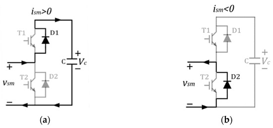
Figure 2.
Fault current path: (a) HBSM for > 0; (b) HBSM for < 0.
Table 2.
FBSM Switching States.
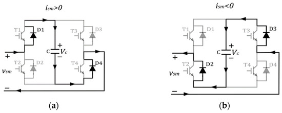
Figure 3.
Fault current path: (a) FBSM for > 0; (b) FBSM for < 0.
A DC side fault event in MMCs can be divided into three stages [43,44,45,46]. In the first stage, the MMC is still able to generate the AC side voltages and therefore the AC side currents remain controlled. So, the fault current in this first stage consists mainly of a DC component due to the discharge of the SM capacitors. The discharge of the capacitors means that the MMC can no longer generate the AC side voltages and starts to lose control of the AC side currents. So, in the second stage, the AC side starts contributing to the fault. Thus, there is an AC component in the fault current in addition to the DC component. In the third stage, all IGBT switches in the SMs are blocked, which prevents the further discharge of capacitors. However, depending on the type of SM used, the AC side may still feed the DC side fault [47] due to the freewheeling diodes in the SMs. The fault stages 1 and 3 are illustrated in Figure 4; stage 2 is omitted since it is merely a combination of stages 1 and 3.

Figure 4.
Pole-to-pole fault current path in HBSM-MMC during (a) Stage 1; (b) Stage 3.
During a DC side fault in the HBSM-MMC, the IGBTs are blocked. For a positive SM current ( > 0) in Figure 2a, diode D1 and the capacitor in each of the SMs are in the fault current path. Therefore, the total capacitor voltage of the HBSMs in each MMC arm would equal . If the fault on the DC side is a pole-to-ground fault, then the peak AC side voltage would be equal to from (1) and (2). Since the reverse voltage generated by the MMC arm would be greater than the peak AC grid phase voltage, diodes D1 in the HBSMs will be reverse biased, and the fault current would be suppressed. However, for < 0, as shown in Figure 2b, the SM capacitors are bypassed entirely, and no reverse voltage would be inserted by the SM capacitors in the current path. Therefore, the AC side source will feed the pole-to-ground fault on the DC side. In the case of a pole-to-pole fault on the DC side, as shown in Figure 5, the peak line-to-line AC side voltage would be . For > 0, the arms of the MMC will insert a total reverse voltage of in each phase while the arms will be bypassed for < 0. The fault current path in the HBSM-MMC for a pole-to-pole fault is shown in Figure 5. Regardless of the type of fault, the HBSM is incapable of blocking the AC grid contribution to the DC fault current.
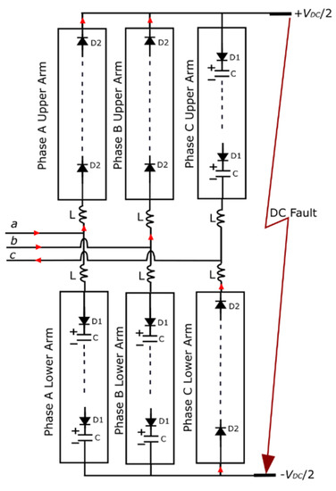
Figure 5.
Fault current path in HBSM-MMC during pole-to-pole fault.
The increased power losses and device cost of additional components have led some researchers to focus on the modification of the HBSM to protect the MMC from overcurrent. The single thyristor switch scheme [48,49] (Figure 6a adds a thyristor across the AC terminals of the traditional HBSM. This thyristor is fired once a DC side fault is detected (Figure 6b). The fault current path shown in Figure 6b is similar to that of Figure 5 except the thyristors are conducting rather than the SM diodes. Since the thyristor current carrying capability is higher than that of diodes, this design helps to protect the diodes from overcurrent during a DC fault. The authors in [50] proposed the double thyristor switch scheme (Figure 6c). When both thyristors are fired after the occurrence of a DC fault, the MMC arms are converted into six RL branches, as shown in Figure 6d. This effectively converts the DC side short circuit into an AC short circuit since the AC side currents sum to zero at the DC poles. The DC fault current decays to zero, but the AC short circuit currents continue to flow in the arms of the MMC, and therefore such a design is only suitable for non-permanent faults.
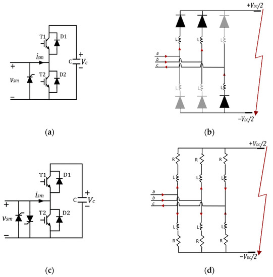
Figure 6.
(a) Single thyristor switch scheme; (b) Single thyristor switch scheme equivalent circuit during fault; (c) Double thyristor switch scheme; (d) Double thyristor switch scheme equivalent circuit during fault.
3. SM Configurations
In the following subsections, the pros and cons of several noteworthy MMC SM configurations with fault blocking capability will be discussed.
3.1. SMs Based on Standard HB and FB Structures
Removing a single IGBT from the standard FBSM results in the unipolar full-bridge submodule (UFBSM) structure [51], as shown in Figure 7. Since D3 is unidirectional, the SM is unable to generate a negative voltage during normal operation. Fault blocking operation remains intact, but overmodulation is no longer possible. This structure features a slightly lower device count than the FBSM, albeit with similar conduction losses.
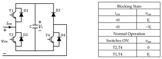
Figure 7.
UFBSM.
Authors in [52] proposed two types of SM by modifying the bypass switch in the traditional HBSM, as shown in Figure 8a,b, respectively. The Type I SM inserts two diodes and one IGBT in the conduction path for the zero-voltage/bypass state. As a result, conduction losses in Type I are higher when compared to Type II SM, which inserts one diode and one IGBT in the conduction path for the zero-voltage/bypass state. Therefore, conduction losses of Type II SMs are comparable to those of the standard HBSM. The proposed structure achieves DC fault blocking by removing the gating signals to the IGBTs. For > 0, the fault current is suppressed by the capacitors. For < 0, the bypass switches that have been turned off prevent the flow of the fault current. This implies that there is no alternate conduction path for the fault current which may create overvoltage and subsequent damage to semiconductor switches. For this reason, the authors proposed the use of RC filters at the AC terminals to provide a path for the fault current. However, the adoption of such filters would lead to an increase in the overall cost.
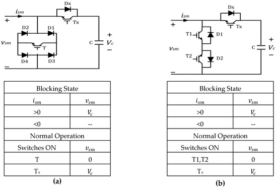
Figure 8.
HBSM with modified bypass switch: (a) Type I; (b) Type II.
3.2. The Clamp Circuit Based Submodules
The diode clamp submodule (DCSM) structure proposed in [53] (Figure 9) is formed by adding two diodes (D3 and D4) and an IGBT (T3) to the standard HBSM. The number of switches in DCSM is the same as that in UFBSM. Similarly, the DCSM does not support bipolar operation. Each SM has two capacitors but there are only two voltage levels available during normal operation. This is because there is no individual control over the insertion of the capacitors into the current path. To ensure an even comparison with other SM configurations, the total voltage () across the two capacitors in the SM is taken to be equal to , implying that, with identical capacitances, the voltage across each would then be . The IGBT T3 is always kept on during normal operation, which means there are two switches in the conduction path, as is the case of the UFBSM/FBSM. During DC faults, the SMs are blocked. When > 0, both capacitors are inserted into the current path to oppose the flow of the current leading to a total reverse voltage of being generated by each arm. For < 0, the current is directed through diode D4 which inserts capacitor C2 into the current path with a total reverse voltage of being inserted into the current path by each arm. For > 0, both capacitors C1 and C2 are utilized for fault blocking while for < 0 only capacitor C2 is available for fault blocking. An asymmetry such as this during fault blocking leads to longer fault current suppression times [54]. One benefit of this SM is that the blocking voltage of T3, D3, and D4 needs to be only , or half the maximum blocking voltage in an FBSM. UFBSMs/FBSMs require all switches to be capable of blocking the full SM voltage ().
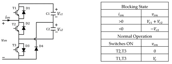
Figure 9.
DCSM.
The clamped double submodule (CDSM) [54], shown in Figure 10, contains two capacitors and can generate three voltage states, 0, , and . CDSM is incapable of generating negative voltages during normal operation. While two FBSMs use a total of four switches to generate the three voltage states, CDSM requires only three switches, resulting in lower conduction losses. During faults, both capacitors are involved in the blocking operation when the SM current direction is positive. For the negative current direction, the SM capacitors are inserted in parallel, and hence the reverse voltage generated per arm is . The equivalent circuit of a CDSM-MMC during a pole-to-pole DC side fault is shown in Figure 11.
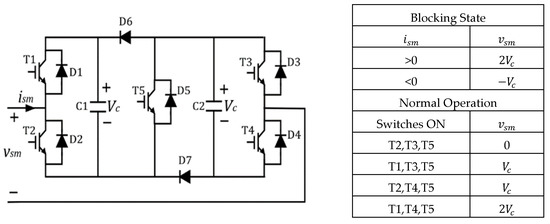
Figure 10.
CDSM.
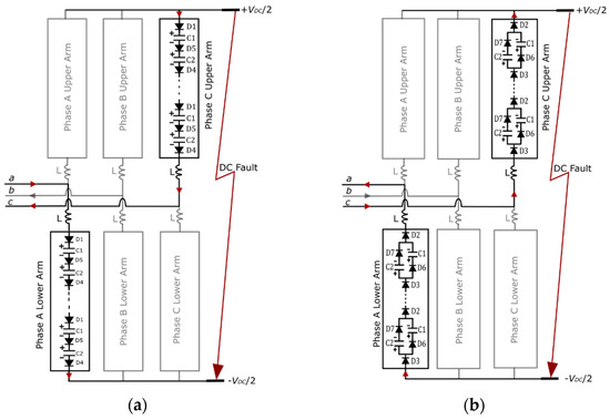
Figure 11.
Fault current path for pole-to-pole fault in the CDSM-MMC, showing one phase for (a) > 0 and (b) < 0.
The semi full-bridge submodule (SFBSM) proposed in [55] and illustrated in Figure 12 is derived from CDSM. The diodes D6 and D7 in CDSM are replaced by active switches to facilitate bipolar operation. This structure allows the SM capacitors to be connected in parallel with either polarity resulting in a reduced number of voltage sensors, which is a definite advantage when sorting algorithms are utilized to ensure SM capacitor voltages in the arms remain nearly constant during MMC operation. For instance, the widely implemented algorithm presented in [56] sorts the SM capacitor voltages in order of magnitude. Afterward, depending upon the arm current direction and the number of SMs to be inserted in the arm (determined in the modulation stage), SMs with the lowest (highest) voltage magnitudes are selected to be in the current path to be charged (discharged). The implementation of such an algorithm requires all SM capacitor voltages to be monitored using voltage sensors. The number of required sensors is equal to the number of capacitors, implying that the sorting algorithm will need a significantly high number of sensors for voltage balancing if each SM contains more than one capacitor. The utilization of the switching state enabling parallel connection of the two capacitors within each SM ensures both capacitors remain at the same voltage level such that only one voltage sensor per SM is sufficient to monitor the capacitor voltages.

Figure 12.
SFBSM.
SFBSM on-state losses are comparable to those of CDSM, as three switches are sufficient to realize output voltage levels 0 and . It is only the parallel connection mode (, ) that involves the use of four switches. Fault blocking is asymmetrical with only capacitor C1 available to suppress the fault current when < 0.
The active clamped T-type submodule (ACTSM) proposed in [57] is unipolar with symmetrical DC fault blocking capability. The SM structure and switching states are shown in Figure 13. When either one of the capacitors is inserted into the current path, three switches are operational. However, when both capacitors are inserted, only two switches are required to be on. This is a definite advantage as two FBSMs require four switches to produce the output level. Conduction losses in ACTSM are seen to be lower compared to those of other symmetrical fault blocking topologies, including the FBSM and the cross connected SMs that will be introduced later.
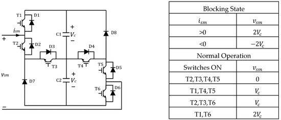
Figure 13.
ACTSM.
Among the clamped SMs, the SFBSM has the highest number of switches in the conduction path and therefore would exhibit the highest conduction losses. However, the reduced voltage sensor requirement is a definite advantage in terms of cost. The CDSM has lower conduction losses but is only capable of unipolar voltage generation, making overmodulation impossible. Meanwhile, the ACTSM has comparable conduction losses when compared to the CDSM and has bipolar voltage generation capability. The only drawback is the lack of the parallel SM capacitor insertion state when compared to the SFBSM.
3.3. The Cross Connected Submodules
The three-level cross connected submodule (TLCCSM) presented in [58] can be thought of as two HBSMs connected in series using a clamp circuit, as illustrated in Figure 14. Fault blocking is symmetrical. However bipolar operation is not possible due to the presence of diodes in the clamp circuit. Four switches need to be operational for the realization of all voltage states, making conduction losses comparable to those of FBSMs. TLCCSM has a lower device cost compared to the FBSM as two of the IGBT switches are replaced with diodes.
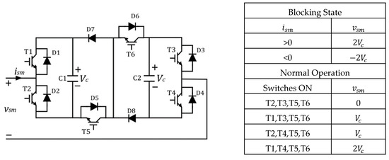
Figure 14.
TLCCSM.
The five-level cross connected submodule (FLCCSM) [59] (Figure 15) is comprised of two HBSMs cross connected using two switches. All five output voltage levels, 0, , , , and , require the operation of three switches, making conduction losses comparable to those in the CDSM. Bipolar voltage output enables operation in the overmodulation region if required. A major shortcoming of FLCCSM is that the clamp switches need to withstand the combined voltage of the two SM capacitors () and may require a series connection of two switches, which will lead to higher conduction losses than that of the FBSM.
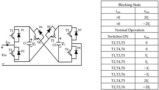
Figure 15.
FLCCSM.
The series-connected double SM (SDSM) [60], also called three level SM in [51], is derived from FLCCSM by the removal of the bidirectional switch T6 and making the switch unidirectional. The outcome is a slight reduction in device count while keeping the DC fault blocking operation symmetrical. However, the SM becomes unipolar as a result.
The FLCCSM has a clear advantage over the TLCCSM in terms of conduction losses Moreover, it has the bipolar voltage generation capability which is missing in the TLCCSM. However, if two IGBTs in series are required to be installed in the clamp switches, then the FLCCSM would become inferior to the TLCCSM from a conduction loss standpoint.
3.4. Other Fault Blocking Submodules
This subsection presents fault blocking SM structures that do not fall under broader categories.
3.4.1. Mixed Submodule
The mixed submodule (MSM) [61,62] is a series connection of an HBSM and any fault blocking submodule. The MSM provides asymmetrical fault blocking due to the presence of HBSMs but has overmodulation capability. The most common type of MSM is formed by combining HBSMs and FBSMs as illustrated in Figure 16. The generation of all voltage levels in such MSM structures requires the operation of three switches, making on-state losses the same as in the CDSM. However, when compared to CDSM, it has one more IGBT and one less diode, resulting in a slight increase in the semiconductor device cost.
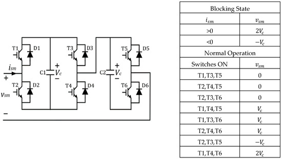
Figure 16.
MSM.
When a single capacitor cell structure such as the FBSM is used in an MSM as the fault blocking SM, replacing 50% of the HBSMs with FBSMs is sufficient to block both pole-to-pole and pole-to-ground faults on the DC side [63]. On the other hand, in an MSM configuration comprised of fault blocking SM containing two capacitors in the cell, the calculation to determine the minimum required number of fault blocking SMs is performed differently as described in [59]. In MSM configurations, if double capacitor SMs with symmetrical fault blocking capability are utilized, 50% of the HBSMs in the mixed configuration will need to be replaced with fault blocking SMs for suppressing pole-to-ground faults while 44% replacement is enough for pole-to-pole fault current clearance [59]. If double capacitor SMs with asymmetric fault blocking capability are used, all SMs in the arms will need to be of the fault blocking type for the suppression of pole-to-ground faults, while an 88% replacement is sufficient when only pole-to-pole fault current suppression is desired.
3.4.2. Composite Submodule
The composite submodule (CSM) proposed in [63] is shown in Figure 17 along with its switching states. Like the SFBSM, CSM has additional voltage states allowing the SM capacitors to be inserted in parallel ( voltage state), which helps with capacitor voltage balancing. The conduction losses in this module are lower than those of SFBSM since the number of switches in the conduction paths for 0 and voltage states are lower than that in SFBSM by one.

Figure 17.
CSM.
3.4.3. Switched Capacitor Submodule
The motivation behind the development of the switched capacitor submodule (SCSM) [64] was to reduce the total number of voltage sensors. The SCSM shown in Figure 18 does not support bipolar operation and provides asymmetrical fault blocking. The 0 and voltage states are obtained using four switches. The voltage state is obtained either by the insertion of an SM capacitor into the circuit using three switches or by the parallel insertion of the SM capacitors (similar to the case of SFBSM), which would increase the number of conducting switches to five. It is noteworthy that the generation of all voltage states requires conduction through one extra switch compared to SFBSM.
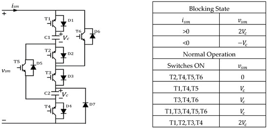
Figure 18.
SCSM.
3.4.4. Double Reverse Blocking Submodule
The double reverse blocking submodule (DRBSM) proposed in [65] is shown in Figure 19. The reverse blocking IGBT (RB-IGBT) unit consists of two antiparallel RB-IGBTs. Symmetrical fault blocking is provided with only two switches in on-state for any of the voltage states. This is an improvement over other SM configurations since conduction losses are comparable to HBSMs. However, the lack of overmodulation capability is considered a drawback.
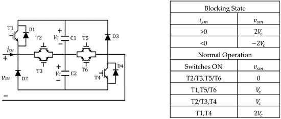
Figure 19.
DRBSM.
3.4.5. Asymmetric Full-Bridge Blocking Submodule
The asymmetric full-bridge submodule (AFBSM) [66], shown in Figure 20, is a bipolar SM capable of asymmetrical fault blocking. During normal operation, only two switches need to be operational to attain the four voltage levels. Hence, the advantage of this configuration is in its low conduction losses. However, switches T1 and T2 need to withstand the sum of the voltages of two capacitors. Therefore, they need to be rated at higher voltages or a series connection of two switches may be required, which would result in increased conduction losses.
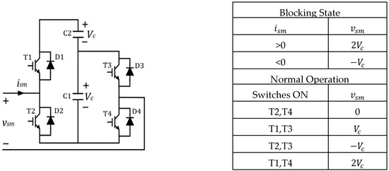
Figure 20.
AFBSM.
4. Comparative Evaluation of Different SM Configurations
A comparison of SM configurations in terms of device count, number of required voltage sensors, number of switches in the conduction path, overmodulation capability, and fault blocking symmetry is provided in Table 3. Among the SM configurations discussed in the previous section, configurations, such as the SFBSM and SCSM that allow the parallel connection of capacitors, are desirable when employing a lower number of voltage sensors is important. The analysis suggests that further research on SCSM and SFBSM configurations would add significant value since employing a lower number of voltage sensors would lead to considerable cost reduction. AFBSM is the preferred configuration if reducing conduction losses is a priority. However, fault blocking in AFBSM is asymmetrical, leading to longer fault current suppression times. Meanwhile, the FLCCSM is capable of both overmodulation and symmetrical fault blocking. For both AFBSM and FLCCSM, the voltage ratings of IGBT switches need to be twice those for other SMs, leading to high cost and conduction losses. MSM (with a mix of HB and FBSMs) and CDSM configurations are similar to FLCCSM in terms of device count and conduction losses. While the CDSM is unipolar which makes overmodulation impossible, the MSM has bipolar voltage generation capability. Moreover, MSM with a mix of HB and FB modules would be commercially viable since significant research has already been conducted on the operation, control, and voltage balancing of such systems, including operation in the overmodulation region.
Table 3.
Comparison among different fault blocking SMs.
5. Hybrid MMC Configurations
Hybrid MMC configurations aim to optimize converter performance in various ways, including combining two different SM configurations or making adjustments in the MMC structure. The majority of hybrid configurations involve the use of FBSMs in a two-level converter structure. The two-level VSC features low semiconductor device requirement compared to MMCs but requires the use of high-frequency pulse width modulation (PWM) to obtain a sinusoidal output voltage of acceptable quality. Moreover, the generation of only two voltage levels requires turning switches on and off under high currents and voltages, leading to high losses in the switches, especially at a high switching frequency. Furthermore, the two-level VSC is not capable of providing DC fault protection. Recent research in this area has involved the placement of FBSMs either on the AC or DC side of the two-level converter leading to various innovative designs. This section will describe such configurations and will touch upon noteworthy hybrid MMCs as well.
5.1. Improved HBSM-Based MMC
Authors in [67] proposed an improved HBSM-based MMC (Figure 21a) where the director switches (, ) and diodes are installed around each arm. During normal operation, the director switches are kept closed and the operation of the improved structure is identical to that of conventional HBSM-MMC. After the occurrence of a DC side fault, all IGBTs in the director switches and the HBSMs are blocked. For the positive arm current direction (Figure 21b), the director switches are shorted, but the HBSM capacitors are capable of providing the necessary reverse voltage. When the current direction reverses, the antiparallel diodes in the director switches block the flow of the arm current. The current is then redirected into the opposite terminal of the MMC arm through the diodes connected in parallel to it such that the current flow direction through the SMs remains the same (Figure 21c). This ensures continued blocking of the fault current by the HBSM capacitors. The director switches will thus need to withstand significant high voltage stresses during faults and ensure conduction through the alternate path.
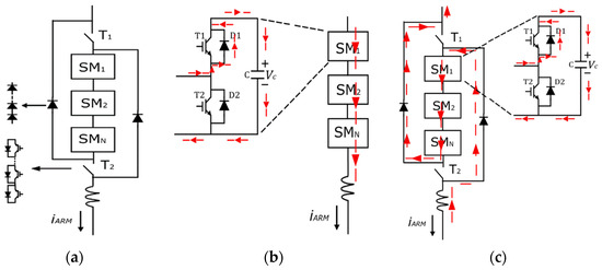
Figure 21.
(a) Improved HBSM-based MMC arm; (b) fault current path through an arm for iARM > 0; (c) fault current path through an arm for iARM < 0.
5.2. Alternate Arm Converter
The alternate arm converter (AAC) [68,69,70] is derived by placing the cascaded FBSMs on the DC side of the standard two-level converter. All six arms of the AAC have a chain link of FBSMs along with director switches, as shown in Figure 22. As in the two-level converter, the high-voltage director switches are operated in complementary pairs for each phase. The presence of the FBSM chains in the arms enables soft-switching of the director switches. Meanwhile, the complementary nature of the director switch operation implies that only one arm is in conduction at a time. Therefore, the upper arm FBSMs are used to construct the AC voltage waveform in the positive half cycle while the lower arm generates the voltage waveform in the negative half cycle. This implies that conduction losses would be about half when compared to FBSM-MMC-based systems. In [71], a semiconductor loss comparison between the AAC and the HCMC was made where simulation results confirmed lower conduction losses in the AAC.
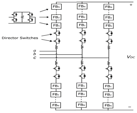
Figure 22.
AAC.
The number of required SMs in the AAC is reduced by half when compared to an equivalent FBSM-MMC. However, there needs to be a short overlap period, during which the conduction of switches is transferred from the upper arm to the lower arm in each phase and vice versa, to facilitate energy balancing in the arms. During this period, both arms conduct and form a path for current to flow between the DC rails. This circulating current can be used to achieve various control objectives such as zero-current switching and arm energy balancing. With a short overlap period, the DC current contains a six-pulse ripple that needs to be filtered out. Besides, a short overlap period makes arm energy balancing challenging as the time window is limited. Several energy balancing methods based on a short overlap period are discussed in [72,73,74].
To address the energy balancing problem in the short overlap period, an extended overlap alternate arm converter (EO-AAC) was proposed in [75], which resulted in a smooth DC current waveform and eliminated the large DC filter capacitor requirement. However, DC side inductors were still essential for current control. In [76], active filtering of the DC current based on internal energy control in the EO-AAC was proposed, which eliminated the need for the DC side inductors, but soft-switching was not achieved. To address this issue, a zero-current switching method for the EO-AAC was proposed in [77].
An important advantage of the AAC over FBSM-MMC is in the minimum capacitor energy storage requirement to ensure SM voltage fluctuations are kept within set limits. It was shown in [78,79] that the capacitive energy storage requirement in the AAC is about one-third of that in FBSM-MMC even in the case of a short overlap period, with a large DC filter capacitor present. In the EO-AAC mode with no capacitive filters, there would be an extra 33% reduction in the energy storage requirements.
5.3. Hybrid Cascaded Multilevel Converters
Hybrid configurations with cascaded FBSM chains on either the AC or the DC side of the MMC are described in this subsection.
5.3.1. Hybrid Cascaded Multilevel Converters with AC Side HBSMs
The authors in [3,80] presented a hybrid cascaded multilevel converter (HCMC) configuration that has a two-level VSC in the main power stage, which is connected in series with cascaded FBSMs on the AC side, as shown in Figure 23. Modulation and control schemes during normal and DC fault conditions for this design were proposed in [81]. This FBSM chain acts as an active filter or a wave-shaping circuit that eliminates the harmonic voltages produced by the two-level converter in the main power stage. The two-level converter produces a square wave output and the wave-shaping circuit compensates for the difference in the output of the two-level converter and the desired (sinusoidal) output voltage. The combined output voltage is an almost perfect sinusoid, which is a significant improvement over the output of the traditional two-level VSC. This allows the two-level converter to switch at a much lower frequency than would be possible in the absence of the wave-shaping converter. The fault blocking ability of the FBSM cells is utilized in the case of DC side faults to suppress the fault current. The cascaded FBSMs must block half the DC link voltage to provide short circuit protection against both pole-to-pole and pole-to-ground faults on the DC side. Since the cascaded SMs are placed on the AC side rather than on the arms, the total SM requirement is reduced to only a quarter compared to the FBSM-MMC while keeping voltage waveform quality and fault blocking ability intact. Placing the wave-shaping circuits on the AC side does not, however, solve the problem of high switching losses in the two-level converter. Even though the two-level converter switches can be switched at a low frequency, switching losses are still high. Moreover, as in the case of traditional two-level converters, large DC link capacitors are required in this configuration. Therefore, high inrush currents due to the recharging of the DC side capacitors during fault recovery represent a drawback of this configuration, leading to high current stress on the switching devices. In [82], it was shown that the HCMC has lower conduction losses than the FBSM-MMC, even when mixed SMs were utilized in the arms instead of HBSMs.
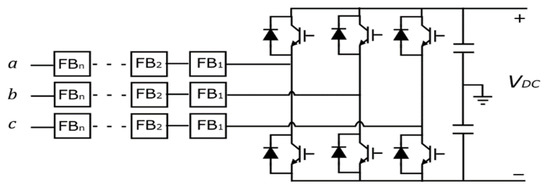
Figure 23.
HCMC.
The hybrid cascaded modular multilevel converter (HC-MMC) with HBSMs in the main circuit presented in [83] replaces the two-level converter in the main power stage of the HCMC with HBSMs. The wave-shaping circuit remains identical to that of the HCMC, as shown in Figure 24. In [84], a control technique to regulate the energy of the wave-shaping part, i.e., the FBSM chains, was proposed. HBSMs in the arms reduce the dv/dt stress on the switching devices and enable better reference voltage tracking for the AC side FBSM chains, thus improving switching synchronization between the two power stages. The FBSM chain in each phase only needs to block half the DC link voltage to facilitate wave-shaping and DC fault blocking, as explained previously. Since the two-level converter is replaced by HBSMs in the main power stage, high switching losses are avoided. In addition, the need to have a DC link capacitor is also eliminated. A drawback of this configuration is that the device count and conduction losses are higher than those of the HCMC due to the use of HBSMs in the main circuit. Both the HCMC configurations have a high degree of control complexity due to the need for synchronization between the main and the wave-shaping circuits.
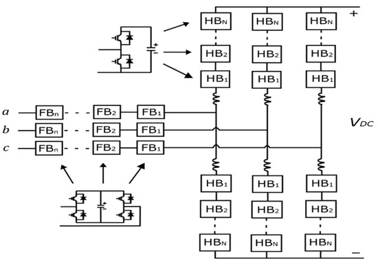
Figure 24.
HC-HCMC.
The H-bridge hybrid modular converter (HBHMC) [85] offers an improvement over the HCMC in terms of capacitor voltage balancing while the main difference between the two structures lies in the use of an H-bridge at the DC terminal in the HBHMC, as shown in Figure 25. The H-bridge provides isolation or freewheeling mode for the load connected on the AC side. This gives an extra degree of freedom for the FBSM capacitor voltage balancing. The HBHMC has two main parts, the main H-bridge circuit (MHBC) and a wave-shaping circuit (WSC). To obtain three-phase AC voltage, three HBHMCs can be connected either in series or in parallel (Figure 26a,b). Similar to the HMC with DC side cascaded cells, this configuration will only be suitable for back-to-back or short-distance HVDC transmission. In this configuration, DC fault blocking is provided by the FBSM chain.
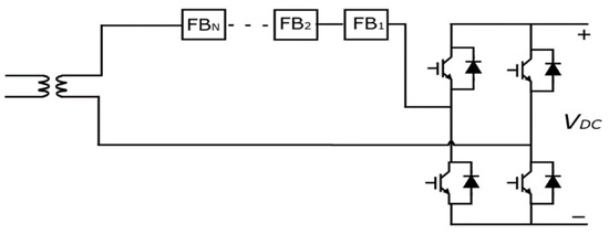
Figure 25.
Single phase diagram of HBHMC.
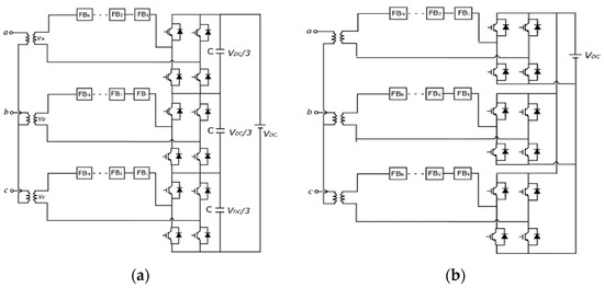
Figure 26.
(a) Series HBHMC; (b) Parallel HBHMC.
5.3.2. Hybrid Cascaded Multilevel Converters with DC Side HBSMs
The HCMC with DC side cascaded FBSMs, as shown in Figure 27, was presented along with a discussion on converter operation and control in [86,87,88,89]. In this configuration, the total voltage across the cascaded FBSMs equals the full DC link voltage (). The difference between and the voltage generated by the FBSM chain produces a rectified voltage across the main H-bridge circuit. The H-bridge circuit then reverses the polarity of this voltage during the negative half of each fundamental cycle to produce an AC signal. The use of the H-bridge at the AC terminal ensures that the converter generates the same voltage levels per phase as the traditional MMC but with half the number of SMs. Furthermore, the main H-bridge switches operate at the fundamental frequency and the switching occurs at near zero-voltage (soft-switching), keeping switching losses to a minimum. The cascaded FBSMs provide the DC side fault protection. A disadvantage of this configuration is that it is only suitable for back-to-back or short-distance HVDC transmission. This is because the DC side voltage is half the peak-to-peak AC side voltage. Therefore, the rated DC side current for a given transmitted power is double when compared to other hybrid configurations.
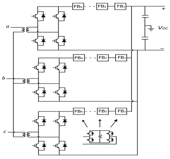
Figure 27.
HMC with DC side HBSMs.
5.4. Series Stacked Hybrid Modular Multilevel Converter
The authors in [90] proposed a three-phase, series-connected MMC (SCMMC) for HVDC applications to reduce the total number of required SMs when compared to the FBSM-based MMC. This structure is incapable of blocking DC side fault currents due to HBSMs in the arms. In [91], the series stacked hybrid modular multilevel converter (SSHMMC) was introduced (Figure 28). By replacing one-third of the HBSMs with FBSMs in this configuration, it is possible to incorporate DC fault blocking capability. The DC link voltage per phase in SSHMMC is . A clear disadvantage of this configuration is that the peak-to-peak voltages obtained on the AC side would also be reduced to one third.

Figure 28.
SSHMMC.
It is evident from Figure 28 that during a DC side fault, six out of the twelve arms of the converter are in the fault current path along with all three of the AC side sources. The three sources are balanced and sinusoidal. Therefore, the maximum value of the AC side voltage at any instant of time is , where is the peak value of phase voltage. Since the maximum AC side voltage is equal to the DC link voltage (per phase), equals . Therefore, the total blocking voltage required to suppress the fault current is . As mentioned previously, each arm of the converter can block . The six arms in series generate a total blocking voltage of . Therefore, to block DC side faults, it is sufficient to have one-third of the SMs with symmetrical fault blocking capability. As a result, there is a reduction in the number of FBSMs required in the arms when compared to the traditional fault blocking hybrid MMC consisting of HBSMs and FBSMs with a 1:1 ratio.
6. Comparative Evaluation of Different Hybrid MMC Configurations
A comparison among the hybrid MMC configurations in terms of the total number of SMs and capacitors, total number of IGBTs, number of IGBTs in conduction path, soft-switching, and overmodulation capabilities are summarized in Table 4. Director switch IGBTs were taken into consideration during the calculation.
Table 4.
Comparison Among Hybrid MMC Configurations.
The AAC has some notable advantages over other configurations. It has a lower number of SMs compared to FBSM-MMC. It exhibits lower switching losses, especially in comparison to HCMC-based structures. Moreover, the capacitor energy storage requirements are much lower compared to FBSM-MMC systems, which would provide significant benefits in terms of cell capacitor sizing. The drawbacks of the conventional AAC configuration include the requirement of a large DC side filter and challenges with arm energy balancing. The EO-AAC eliminates the need for the DC filter but is unable to facilitate soft-switching. Meanwhile, the HCMC topology has the lowest device count. However, HCMC with DC side cascaded HBSMs and the parallel HBHMC are only suitable for short-distance HVDC transmission. The series HBHMC and the SSHMC are more appropriate for low-power applications. However, the HBHMC is incapable of soft-switching. Therefore, the AAC remains the most promising configuration in terms of commercialization if the aforementioned issues are alleviated through further research and development. Table 5 provides a summary of the main features of notable MMC configurations.
Table 5.
Comparison among MMC Configurations.
7. STATCOM Operation and DC Fault Ride-Through
During a DC fault, the HVDC link voltage collapses, and active power cannot be transferred between the AC and DC sides. The MMC can be operated as a STATCOM to provide reactive power support to the AC system during this period. In the STATCOM operation mode, certain changes are required to be made with respect to control and arm/leg energy balancing in the MMC.
During the normal operation of MMC, the reference voltages used for modulation of the upper and lower arms ( and ) are expressed as,
where denotes the leg internal voltage which is generated due to the flow of circulating current. If all the SMs are blocked, the MMC cannot supply reactive power to the AC grid. Instead, if the converter is allowed to operate with the term in the arm reference voltage synthesized as zero [92,93], then the DC fault will be cleared. Positive and negative excursions of the MMC arm voltages will enable them to operate as wave-shaping circuits and control the AC currents. As long as the SMs have bipolar voltage generation capability, the MMC can ride through the fault and operate as a STATCOM to provide reactive power support to the AC grid. The following subsections review some DC FRT strategies and the STATCOM operation mode of a selected subset of MMC configurations discussed thus far. The modifications of the arm/leg energy balancing controllers during STATCOM operation mode are discussed briefly as well.
7.1. Hybrid Arm Based Bipolar MMC
The hybrid-arm-based bipolar MMC [94] is a hybrid configuration where the arms connected to the ground pole are comprised of HBSMs while the arms connected to the positive and negative poles can be any type of fault blocking SM. The positive and negative poles are at and , respectively, with respect to the ground pole. During both pole-to-pole and pole-to-ground faults, the fault blocking modules connected to the positive and the negative poles are blocked, enabling the HBSMs to operate as a STATCOM. Figure 29 shows such a bipolar MMC comprised of UFBSMs and HBSMs. This is a very simple and cost-effective way of achieving DC FRT ability since the fault blocking SMs required do not need to have bipolar capability for the converter to work as a STATCOM during DC faults.
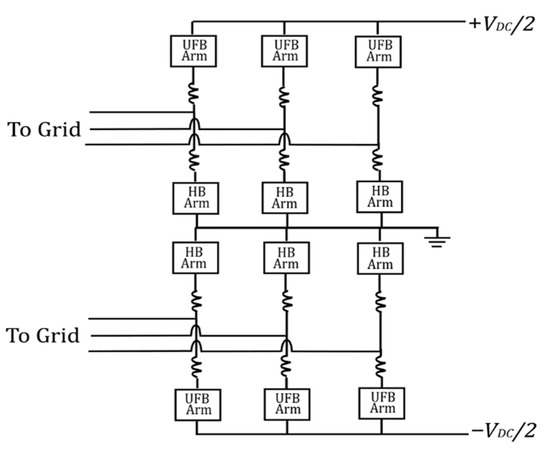
Figure 29.
UFBSM-based hybrid arm bipolar MMC.
7.2. STATCOM Operation Mode of the AAC
The bipolar voltage generation capability of the AAC enables it to operate in STATCOM mode during DC faults. Two different modes of operation are presented in [95] depending on the conduction of the arms. The first mode of operation is similar to the normal operation mode of the AAC. The upper and lower arms of each phase conduct alternately. This mode will result in the current flowing through the DC side fault, which is not desirable. In the second mode of operation, either all the upper arms or all the lower arms are utilized during the STATCOM operation. This implies that the upper or the lower arms can function as star-connected STATCOMs. The current will be constrained to flow within the arms and will not flow into the DC side.
7.3. STATCOM Operation of Unipolar SM Configurations
The CDSM is incapable of bipolar voltage generation rendering it unsuitable for STATCOM operation during DC faults. However, the authors of [96] identify switching states for bipolar operation of the CDSM, but only when the SM current direction is negative. This implies that the CDSM can operate as a STATCOM during DC faults if the arms are made to conduct alternately. The switching states for the STATCOM mode of the CDSM are shown in Table 6, where the “Positive” and “Negative” states denote the bipolar SM voltages for < 0. These switching states are utilized only when there is a DC side fault. The converter is then able to clear the fault and work as a STATCOM. A disadvantage of such a STATCOM mode of operation is that it will have half the reactive power capability compared to MMCs containing bipolar SMs.
Table 6.
CDSM STATCOM Mode Switching States.
As discussed in the previous paragraph, if alternate switching states exist for bipolar SM voltage generation for a certain direction of SM current, then the STATCOM operation of such unipolar SM configurations during DC faults may be realized by the alternate conduction of the arms. The UFBSM is one such fault blocking module that cannot generate bipolar voltages for both directions of SM current. However, alternate switching states with bipolar voltage output for < 0 exist and are illustrated in Table 7. Therefore, DC fault blocking and STATCOM operation are made possible by the alternate conduction of arms. Similar to the CDSM, a downside is that it will have half the reactive power capability compared to MMCs containing bipolar SMs.
Table 7.
UFBSM STATCOM Mode Switching States.
In [97], the authors propose the STATCOM operation of a hybrid HBSM-SDSM with a mix of 30% of SDSM per arm. As mentioned earlier, the SDSM (Figure 30) is a unipolar module that cannot be operated as a STATCOM during DC faults if the switching states for normal operation are employed. Therefore, just as was the case with the CDSM and UFBSM, the arms are alternately blocked based on the current direction and an alternate set of bipolar voltage states is realized for < 0. The switching states for the STATCOM operation mode of the SDSM are provided in Table 8. The line-line voltage generated by the alternate blocking and conduction of the arms during STATCOM mode is higher compared to the CDSM-based STATCOM, resulting in superior reactive power capabilities.

Figure 30.
SDSM.
Table 8.
SDSM STATCOM Mode Switching States.
7.4. Energy Balancing during STATCOM Mode of Operation
Capacitor energy balance in an MMC is essential to ensure proper operation of the converter and applies to both leg and arm. Voltage/energy balancing of the SM capacitors can be achieved either through non-energy- or energy-based methods. The non-energy-based algorithms are usually simpler to implement and do not require any modifications during DC faults in the MMC.
In the case of the UFBSM/HBSM-based bipolar MMC [94], the outer control loop was modified to facilitate converter energy control. The d-axis current reference was not obtained from the active power in the outer loop during STATCOM operation. Rather, a PI controller was utilized to generate the d-axis current reference such that the average capacitor voltage of the HBSMs was maintained near their nominal ratings. This enabled control over the total energy flowing into the MMC during the STATCOM mode of operation. The conventional sorting algorithm was used to keep the capacitor voltages balanced within the arms.
In [17], an energy-based voltage balancing method was proposed whereby arm and leg energy in the MMC can be controlled by the injection of circulating currents. Expressions for the sum and difference of power flowing into the arms of an MMC are given by (8) and (9), respectively,
The first term on the right-hand side of (8) can be controlled by injection of a DC component in the circulating current (), allowing leg energy balancing to be carried out during normal MMC operation [17,92,98]. Meanwhile, the second term on the right-hand side of (9) can be utilized for arm energy balancing by the injection of a fundamental frequency component in the circulating current. However, in the event of a DC fault, is synthesized as zero to clear the fault and operate the MMC in STATCOM mode. Therefore, the term in (8) becomes zero and leg energy control is no longer possible. In [93], a common-mode voltage (CMV) injection in the FBSM-MMC was proposed to carry out leg energy balancing during DC faults in the MMC. The CMV () is defined as the potential difference that exists between the neutral points of the AC and DC sides. Expressions for the CMV and the AC side current are,
The power generated in the MMC legs due to the injected common-mode voltage is given by,
The three-phase powers are converted to the dq frame components and the reference for the CMV is obtained as,
where and represent the reference values of the leg powers in the dq frame, while and are the AC side d- and q-axis current components, respectively. By controlling the phase and amplitude of the CMV, it would then be possible to vary the power flowing into the legs of the MMC and continue to carry out leg energy balancing during the STATCOM operation mode.
When the CDSM-MMC is working in STATCOM mode during a DC side fault [96], the arms of the CDSM-MMC are conducting and being blocked alternately. Thus, the equivalent circuit of the DC faulted CDSM-MMC during STATCOM mode is different from when it is operating under normal conditions. The circulating current injection method for energy balancing is no longer feasible since no circulating current exists within the same phase due to the alternate conduction of the CDSM arms. Although the CMV injection method from [92] can be employed for leg energy balancing, a simpler strategy was presented in [96] where dq transformation is not required. As the RMS value of the capacitor voltages in an arm is indicative of the arm’s energy level, in this strategy, the sum and difference of the arm power expressions for the conducting lower and upper arms, in terms of the RMS voltages of the SM capacitors, were split into two parts to denote powers flowing from the DC and AC sides into the conducting arms. The expression for the power flowing from the DC side into the conducting arms includes the CMV term. An increase in CMV leads to a decrease in the power flow in the conducting upper arm(s) and an increase in the power flow in the conducting lower arm(s), respectively. Consequently, the difference in the energy levels between the conducting upper and lower arms will decrease. Similarly, a decrease in the CMV leads to an increase in the power flow in the conducting upper arm(s) and a decrease in the power flow in the conducting lower arm(s), respectively. The reference value of the CMV is obtained from a PI controller based on the difference in RMS voltages of the SM capacitors in conducting upper and lower arms. Therefore, the CMV reference can be adjusted based on the RMS voltage of SM capacitors, and no circulating current injection is necessary for arm energy balancing. In addition, the outer controllers are adjusted to control the total converter energy in the same way as in [94].
Authors in [99,100] proposed an energy balancing approach based on either AC or DC power. The variation of energy in the SMs is dependent on the instantaneous AC power and the power exchanged with the DC bus. Based on the energy balance equation, a controller can be designed using the AC power or the DC power in the outer loop. The references generated by the outer loop are the AC grid currents and the circulating currents. When the outer controller is based on AC power, it is not possible to implement three separate loops for the grid currents. Therefore, only the control of total MMC energy is possible as opposed to individual arm/leg energy balancing. In [101], this idea was expanded and implemented to achieve energy balancing during a DC fault. During normal operation, energy balancing was performed using DC power. After the occurrence of a DC fault, the energy balancing was shifted to AC power mode since the loss of the DC voltage made DC power-based control impossible. However, in the AC power-based control, leg/arm energy balancing is not feasible since any circulating current injection intended for balancing may not add up to zero and flow into the DC fault. Therefore, the authors suggest the use of coupling matrices to ensure that the AC components of circulating currents sum to zero and do not flow through the DC fault. This method has the added advantage of achieving low transient overvoltage in the arms during the fault in addition to DC fault clearance and reactive power injection into the AC grid.
To summarize, the CMV injection method for leg energy balancing can be applied to any SM configuration with continuous conduction of both arms in a phase. The capacitor energy-based method, which was originally developed for the CDSM-STATCOM, can also be utilized for arm energy balancing during the STATCOM mode of operation of MMCs with other types of unipolar SMs. The AC power-based energy balancing method is more complex but can be used if better transient response/stability is desired.
8. Conclusions
In this paper, a variety of noteworthy SM and hybrid MMC configurations with DC fault blocking capability were reviewed and compared from different viewpoints, including the number of switches in the conduction path, fault blocking symmetry, voltage stress per device, device count, number of voltage sensors, overmodulation, soft switching, voltage balancing capability, and control complexity. Based on the comparisons made, several configurations, such as asymmetrical full-bridge submodule and mixed submodule, were identified, which hold an advantage in terms of lower conduction losses or total semiconductor device count, while SM configurations such as semi full-bridge submodule and switched capacitor were associated with better performance in terms of voltage balancing capability and control simplicity. When overmodulation is a requirement, mixed and asymmetrical full-bridge submodules are suitable choices. Meanwhile, the semi full-bridge submodule was identified as the proper candidate when a lower number of voltage sensors along with reduced control complexity is desired. Among hybrid topologies, the alternate arm converter was found to be the most efficient with a low device count, while the hybrid converter with cascaded DC side cells was recognized as a suitable configuration for short-distance HVDC transmission.
The STATCOM operation mode of the full-bridge MMC, alternative arm converter, hybrid MMCs, as well as MMCs based on unipolar SMs, such as clamped-double and unipolar full-bridge submodule, were discussed and compared in this paper. This shows that the adjustment of the arm voltage reference enables bipolar SMs to work as wave-shaping circuits, allowing the provision of reactive power support to the AC grid during a DC fault. Furthermore, MMCs with unipolar SMs can also work as STATCOMs during DC faults, if alternate switching states that enable bipolar operation exist for a certain direction of SM current. However, due to the alternate arm conduction during STATCOM mode, such unipolar SMs have half the reactive power capability of the bipolar SMs.
This paper also provides a review of different methods used to provide arm and leg energy balancing in MMCs when they are operated as STATCOMs during DC faults. One of the most notable methods is common-mode voltage injection, which can be applied to any SM configuration provided there is continuous conduction of both arms in a phase. The capacitor energy-based method for arm energy balancing during STATCOM operation of the clamped-double submodule can be applied to other unipolar SMs as well.
Author Contributions
Conceptualization, M.N.S., S.P.A. and M.K.; methodology, M.N.S.; validation, S.P.A. and M.K.; formal analysis, M.N.S.; investigation, M.N.S.; resources, S.P.A. and M.K.; writing—original draft preparation, M.N.S.; writing—review and editing, S.P.A. and M.K.; visualization, M.N.S.; supervision, S.P.A. and M.K.; project administration, S.P.A. and M.K. All authors have read and agreed to the published version of the manuscript.
Funding
This research was funded by a Discovery Grant provided by the Natural Sciences and Engineering Research Council (NSERC) of Canada and an Ontario Graduate Scholarship (OGS) provided by the provincial Government of Ontario, Canada.
Institutional Review Board Statement
Not applicable.
Informed Consent Statement
Not applicable.
Data Availability Statement
Not applicable.
Conflicts of Interest
The authors declare no conflict of interest.
References
- Oni, O.; Davidson, I.; Mbangula, K. A review of LCC-HVDC and VSC-HVDC technologies and applications. In Proceedings of the IEEE 16th International Conference on Environment and Electrical Engineering (EEEIC), Florence, Italy, 7–10 June 2016; pp. 1–7. [Google Scholar]
- Lesnicar, A.; Marquardt, R. An innovative modular multilevel converter topology suitable for a wide power range. In Proceedings of the 2003 IEEE Bologna Power Tech Conference Proceedings, Bologna, Italy, 23–26 June 2003. [Google Scholar]
- Adam, G.; Ahmed, K.; Finney, S.; Bell, K.; Williams, B. New Breed of Network Fault-Tolerant Voltage-Source-Converter HVDC Transmission System. IEEE Trans. Power Syst. 2013, 28, 335–346. [Google Scholar] [CrossRef]
- Dekka, A.; Wu, B.; Fuentes, R.L.; Perez, M.; Zargari, N.R. Evolution of Topologies, Modeling, Control Schemes, and Applications of Modular Multilevel Converters. IEEE J. Emerg. Sel. Top. Power Electron. 2017, 5, 1631–1656. [Google Scholar] [CrossRef]
- Ning, L.; Tai, N.; Zheng, X.; Huang, W.; Nadeem, M.H. Detection and classification of MMC-HVDC transmission line faults based on one-terminal transient current signal. In Proceedings of the 2017 IEEE Power & Energy Society General Meeting, Chicago, IL, USA, 16–20 July 2017. [Google Scholar]
- Cui, S.; Sul, S.-K. A Comprehensive DC Short-Circuit Fault Ride Through Strategy of Hybrid Modular Multilevel Converters (MMCs) for Overhead Line Transmission. IEEE Trans. Power Electron. 2016, 31, 7780–7796. [Google Scholar] [CrossRef]
- Hu, J.; Xu, K.; Lin, L.; Zeng, R. Analysis and enhanced control of hybrid-MMC-based HVDC systems during asymmetrical DC voltage faults. IEEE Trans. Power Deliv. 2017, 32, 1394–1403. [Google Scholar] [CrossRef]
- Jonsson, T.; Maiti, P.; Jiang-Häfner, Y. Converter technologies and functional requirements for reliable and economical HVDC grid design. In Proceedings of the 2013 CIGRE Canada Conference, Calgary, AB, Canada, 9–11 September 2013. [Google Scholar]
- Hajian, M.; Zhang, L.; Jovcic, D. DC transmission grid with low-speed protection using mechanical DC circuit breakers. IEEE Trans. Power Deliv. 2015, 30, 1383–1391. [Google Scholar] [CrossRef] [Green Version]
- He, Z.; Hu, J.; Lin, L.; Zeng, R. Mechanical DC circuit breakers and FBSM-based MMCs in a high-voltage MTDC network: Coordinated operation for network riding through dc fault. In Proceedings of the International Conference on Renewable Power Generation (RPG 2015), Beijing, China, 17–18 October 2015. [Google Scholar]
- Stumpe, M.; Tünnerhoff, P.; Dave, J.; Schnettler, A.; Ergin, D.; Schön, A.; Würflinger, K.; Schettler, F. DC fault protection for modular multi-level converter-based HVDC multi-terminal systems with solid state circuit breakers. IET Gener. Transm. Distrib. 2018, 12, 3013–3020. [Google Scholar] [CrossRef]
- Mokhberdoran, A.; Carvalhoa, A.; Silva, N.; Leite, H.; Carrapatoso, A. Design and implementation of fast current releasing DC circuit breaker. Electr. Power Syst. Res. 2017, 151, 218–232. [Google Scholar] [CrossRef]
- Meyer, C.; Doncker, R.D. LCC analysis of different resonant circuits and solid-state circuit breakers for medium-voltage grids. IEEE Trans. Power Deliv. 2006, 21, 1414–1420. [Google Scholar] [CrossRef]
- Wang, S.; Li, C.; Adeuyi, O.D.; Li, G.; Ugalde-Loo, C.E.; Liang, J. Coordination of MMCs with Hybrid DC Circuit Breakers for HVDC Grid Protection. IEEE Trans. Power Deliv. 2019, 34, 11–22. [Google Scholar] [CrossRef] [Green Version]
- Song, S.-M.; Kim, J.-Y.; Choi, S.-S.; Kim, I.-D.; Choi, S.-K. New Simple-Structured AC Solid-State Circuit Breaker. IEEE Trans. Ind. Electron. 2018, 65, 8455–8463. [Google Scholar] [CrossRef]
- Debnath, S.; Qin, J.; Bahrani, B.; Saeedifard, M.; Barbosa, P. Operation, control, and applications of the modular multilevel converter: A Review. IEEE Trans. Power Electron. 2015, 30, 37–53. [Google Scholar] [CrossRef]
- Antonopoulos, A.; Angquist, L.; Nee, H.-P. On dynamics and voltage control of the Modular Multilevel Converter. In Proceedings of the 2009 13th European Conference on Power Electronics and Applications, Barcelona, Spain, 8–10 September 2009. [Google Scholar]
- Perez, M.A.; Bernet, S.; Rodriguez, J.; Kouro, S.; Lizana, R. Circuit Topologies, Modeling, Control Schemes, and Applications of Modular Multilevel Converters. IEEE Trans. Power Electron. 2015, 30, 4–7. [Google Scholar] [CrossRef]
- Perez, M.A.; Ceballos, S.; Konstantinou, G.; Pou, J.; Aguilera, R.P. Modular Multilevel Converters: Recent Achievements and Challenges. IEEE Open J. Ind. Electron. Soc. 2021, 2, 224–239. [Google Scholar] [CrossRef]
- Farias, J.V.M.; Cupertino, A.F.; Pereira, H.A.; Seleme, S.I. On Converter Fault Tolerance in MMC-HVDC Systems: A Comprehensive Survey. IEEE J. Emerg. Sel. Top. Power Electron. 2021, 9, 7459–7470. [Google Scholar] [CrossRef]
- Sakib, M.N.; Azad, S.P.; Kazerani, M. A Review of DC Fault Blocking Converters for HVDC Transmission Systems. In Proceedings of the CIGRE Canada Conference, Toronto, ON, Canada, 19–22 October 2020. [Google Scholar]
- Wan, Y.; Mao, M.; Zhou, L.; Xi, X.; Xie, B.; Zhou, S. Review on topology-based dc short-circuit fault ride-through strategies for MMC-based HVDC system. IET Power Electron. 2020, 13, 203–220. [Google Scholar] [CrossRef]
- Nguyen, T.H.; Hosani, K.A.; Moursi, M.S.E.; Blaabjerg, F. An Overview of Modular Multilevel Converters in HVDC Transmission Systems with STATCOM Operation during Pole-to-Pole DC Short Circuits. IEEE Trans. Power Electron. 2019, 34, 4137–4160. [Google Scholar] [CrossRef]
- Sousa, R.; Mendonça, D.D.C.; Amorim, W.C.S.; Cupertino, A.F.; Pereira, H.A.; Teodorescu, R. Comparison of Double Star Topologies of Modular Multilevel Converters in STATCOM Application. In Proceedings of the 2018 13th IEEE International Conference on Industry Applications (INDUSCON), Sao Paulo, Brazil, 12–14 November 2018; pp. 622–629. [Google Scholar]
- Akagi, H. Classification, terminology, and application of the modular multilevel cascade converter (MMCC). In Proceedings of the 2010 International Power Electronics Conference—ECCE ASIA, Sapporo, Japan, 19 April 2011; pp. 508–515. [Google Scholar] [CrossRef]
- Thitichaiworakorn, N.; Hagiwara, M.; Akagi, H. Experimental verification of a modular multilevel cascade inverter based on double-star bridge-cells (MMCI-DSBC). In Proceedings of the 2012 IEEE Energy Conversion Congress and Exposition (ECCE), Raleigh, NC, USA, 15–20 September 2012. [Google Scholar]
- Song, Q.; Yang, W.; Zhao, B.; Xu, S.; Rao, H.; Zhu, Z. Energy Storage Requirement Reduction Using Negative-Voltage States of a Full-Bridge Modular Multilevel Converter. IEEE Trans. Power Electron. 2019, 34, 5243–5255. [Google Scholar] [CrossRef]
- Wang, K.; Song, Q.; Xu, S. Analysis and Design of the Energy Storage Requirement of Hybrid Modular Multilevel Converters Using Numerical Integration and Iterative Solution. Energies 2022, 15, 1225. [Google Scholar] [CrossRef]
- Hagiwara, M.; Akagi, H. Control and Experiment of Pulsewidth-Modulated Modular Multilevel Converters. IEEE Trans. Power Electron. 2009, 24, 1737–1746. [Google Scholar] [CrossRef]
- Durrant, M.; Werner, H.; Abbott, K. Model of a VSC HVDC terminal attached to a weak AC system. In Proceedings of the 2003 IEEE Conference on Control Applications, CCA 2003, Istanbul, Turkey, 25 June 2003. [Google Scholar]
- Durrant, M.; Werner, H.; Abbott, K. Modelling and controller design for VSC-HVDC attached to an AC network. In Proceedings of the European Control Conference (ECC), Cambridge, UK, 1–4 September 2003. [Google Scholar]
- Farag, A.; Durrant, M.; Werner, H.; Abbott, K. Robust control of a VSC HVDC terminal attached to a weak AC system. In Proceedings of the 2003 IEEE Conference on Control Applications, CCA 2003, Istanbul, Turkey, 25 June 2003. [Google Scholar]
- Meshram, P.M.; Borghate, V.B. A Simplified Nearest Level Control (NLC) Voltage Balancing Method for Modular Multilevel Converter (MMC). IEEE Trans. Power Electron. 2015, 30, 450–462. [Google Scholar] [CrossRef]
- Hu, P.; Jiang, D. A Level-Increased Nearest Level Modulation Method for Modular Multilevel Converters. IEEE Trans. Power Electron. 2015, 30, 1836–1842. [Google Scholar] [CrossRef]
- McGrath, B.; Holmes, D. Multicarrier PWM strategies for multilevel inverters. IEEE Trans. Industrial Electron. 2002, 49, 858–867. [Google Scholar] [CrossRef]
- Konstantinou, G.; Ciobotaru, M.; Agelidis, V. Analysis of multi-carrier PWM methods for back-to-back HVDC systems based on modular multilevel converters. In Proceedings of the IECON 2011—37th Annual Conference of the IEEE Industrial Electronics Society, Melbourne, VI, Australia, 7–10 November 2011. [Google Scholar]
- Li, B.; Yang, R.; Xu, D.; Wang, G.; Wang, W.W.; Xu, D. Analysis of the Phase-Shifted Carrier Modulation for Modular Multilevel Converters. IEEE Trans. Power Electron. 2015, 30, 297–310. [Google Scholar] [CrossRef]
- Huang, M.; Zou, J.; Ma, X. An Improved Phase-Shifted Carrier Modulation for Modular Multilevel Converter to Suppress the Influence of Fluctuation of Capacitor Voltage. IEEE Trans. Power Electron. 2016, 31, 7404–7416. [Google Scholar] [CrossRef]
- Ricardo, L.F.; Pérez, M.A.; Rodríguez, J. DC voltage balance control in a modular multilevel cascaded converter. In Proceedings of the IEEE International Symposium on Industrial Electronics (ISIE), Hangzhou, China, 28–31 May 2012. [Google Scholar]
- Li, X.; Song, Q.; Li, J.; Liu, W.W. Capacitor voltage balancing control based on CPS-PWM of Modular Multilevel Converter. In Proceedings of the IEEE Energy Conversion Congress and Exposition, ECCE, Phoenix, AZ, USA, 17–22 September 2011. [Google Scholar]
- Du, S.; Liu, J.; Liu, T. Modulation and Closed-Loop-Based DC Capacitor Voltage Control for MMC with Fundamental Switching Frequency. IEEE Trans. Power Electron. 2015, 30, 327–338. [Google Scholar] [CrossRef]
- Adam, G.P.; Davidson, I.E. Robust and Generic Control of Full-Bridge Modular Multilevel Converter High-Voltage DC Transmission Systems. IEEE Trans. Power Deliv. 2015, 30, 2468–2476. [Google Scholar] [CrossRef] [Green Version]
- Li, B.; He, J.; Tian, J.; Feng, Y.; Dong, Y. DC fault analysis for modular multilevel converter-based system. J. Mod. Power Syst. Clean Energy 2017, 5, 275–282. [Google Scholar] [CrossRef] [Green Version]
- Xu, Z.; Xiao, H.; Xiao, L.; Zhang, Z. DC Fault Analysis and Clearance Solutions of MMC-HVDC Systems. Energies 2018, 11, 941. [Google Scholar] [CrossRef] [Green Version]
- Wang, Y.; Yang, B.; Zuo, H.; Liu, H.; Yan, H. A DC short-circuit fault ride through strategy of MMC-HVDC based on the cascaded star converter. Energies 2018, 11, 2079. [Google Scholar] [CrossRef] [Green Version]
- Wang, Y.; Yuan, Z.; Fu, J.; Li, Y.; Zhao, Y. A feasible coordination protection strategy for MMC-MTDC systems under DC faults. Int. J. Electr. Power Energy Syst. 2017, 90, 103–111. [Google Scholar] [CrossRef]
- Zhang, G.; Chen, Y.; Yue, C.; Qi, L.; Pan, J. DC pole-to-pole short-circuit behavior analysis of modular multilevel converter. In Proceedings of the 2014 IEEE Energy Conversion Congress and Exposition (ECCE), Pittsburgh, PA, USA, 14–18 September 2014. [Google Scholar]
- Zhang, H.; Luo, L.; Jia, L.; Yang, L.; Yang, S. An Improved Sub-Module Topology for Protecting MMC Power Devices under DC-side Short Circuit Fault. In Proceedings of the 2018 Chinese Control and Decision Conference (CCDC), Shenyang, China, 9–11 June 2018. [Google Scholar]
- Friedrich, K. Modern HVDC PLUS application of VSC in Modular Multilevel Converter topology. In Proceedings of the 2010 IEEE International Symposium on Industrial Electronics, Bari, Italy, 4–7 July 2010. [Google Scholar]
- Li, X.; Song, Q.; Liu, W.; Rao, H.; Xu, S.; Li, L. Protection of Nonpermanent Faults on DC Overhead Lines in MMC-Based HVDC Systems. IEEE Trans. Power Deliv. 2013, 28, 483–490. [Google Scholar] [CrossRef]
- Qin, J.; Saeedifard, M.; Rockhill, A.; Zhou, R. Hybrid Design of Modular Multilevel Converters for HVDC Systems Based on Various Submodule Circuits. IEEE Trans. Power Deliv. 2015, 30, 385–394. [Google Scholar] [CrossRef]
- Ahmed, K.H.; Adam, G.P.; Abdelsalam, I.A.; Aboushady, A.A. Modular multilevel converter with modified half-bridge submodule and arm filter for DC transmission systems with DC fault blocking capability. IET Power Electron. 2018, 11, 2253–2262. [Google Scholar] [CrossRef] [Green Version]
- Li, X.; Liu, W.; Song, Q.; Rao, H.; Xu, S. An enhanced MMC topology with DC fault ride-through capability. In Proceedings of the IECON 2013—39th Annual Conference of the IEEE Industrial Electronics Society, Vienna, Austria, 10–13 November 2013. [Google Scholar]
- Marquardt, R. Modular Multilevel Converter: An universal concept for HVDC-Networks and extended DC-Bus-applications. In Proceedings of the 2010 International Power Electronics Conference—ECCE ASIA, Sapporo, Japan, 21–24 June 2010. [Google Scholar]
- Ilves, K.; Bessegato, L.; Harnefors, L.; Norrga, S.; Nee, H.-P. Semi-full-bridge submodule for modular multi-level converters. In Proceedings of the 2015 9th International Conference on Power Electronics and ECCE Asia (ICPE-ECCE Asia), Seoul, Korea, 1–5 June 2015. [Google Scholar]
- Saeedifard, M.; Iravani, R. Dynamic Performance of a Modular Multilevel Back-to-Back HVDC System. IEEE Trans. Power Deliv. 2010, 25, 2903–2912. [Google Scholar] [CrossRef]
- Hu, X.; Zhang, J.; Xu, S.; Jiang, Y. Investigation of a new modular multilevel converter with DC fault blocking capability. In Proceedings of the 2017 IEEE Energy Conversion Congress and Exposition (ECCE), Cincinnati, OH, USA, 1–5 October 2017. [Google Scholar]
- Li, R.; Fletcher, J.E.; Xu, L.; Holliday, D.; Williams, B.W. A Hybrid Modular Multilevel Converter with Novel Three-Level Cells for DC Fault Blocking Capability. IEEE Trans. Power Deliv. 2015, 30, 2017–2026. [Google Scholar] [CrossRef] [Green Version]
- Nami, A.; Wang, L.; Dijkhuizen, F.; Shukla, A. Five level cross connected cell for cascaded converters. In Proceedings of the 2013 15th European Conference on Power Electronics and Applications (EPE), Lille, France, 2–6 September 2013. [Google Scholar]
- Zhang, J.; Zhao, C. The Research of SM Topology with DC Fault Tolerance in MMC-HVDC. IEEE Trans. Power Deliv. 2015, 30, 1561–1568. [Google Scholar] [CrossRef]
- Adam, G.; Ahmed, K.; Williams, B. Mixed cells modular multilevel converter. In Proceedings of the 2014 IEEE 23rd Interna-tional Symposium on Industrial Electronics (ISIE), Istanbul, Turkey, 1–4 June 2014. [Google Scholar]
- Zeng, R.; Xu, L.; Yao, L. An improved modular multilevel converter with DC fault blocking capability. In Proceedings of the 2014 IEEE PES General Meeting|Conference & Exposition, National Harbor, MD, USA, 27–31 July 2014. [Google Scholar]
- Zhang, J.; Jiang, C.; Han, Y. Modular multilevel converter composite submodule topology and control. J. Eng. 2019, 2019, 2643–2648. [Google Scholar] [CrossRef]
- Elserougi, A.A.; Massoud, A.M.; Ahmed, S. A Switched-Capacitor Submodule for Modular Multilevel HVDC Converters with DC-Fault Blocking Capability and a Reduced Number of Sensors. IEEE Trans. Power Deliv. 2016, 31, 313–322. [Google Scholar] [CrossRef]
- Yao, Y.; Zhang, Y.; Qu, X.; Chen, W. A Modular Multilevel Converter with Novel Double Reverse Blocking Sub-Modules for DC Fault Current Blocking Capability. IEEE Trans. Circuits Syst. II Express Briefs 2020, 67, 740–744. [Google Scholar] [CrossRef]
- Nami, A.; Liang, J.; Dijkhuizen, F.; Demetriades, G.D. Modular Multilevel Converters for HVDC Applications: Review on Converter Cells and Functionalities. IEEE Trans. Power Electron. 2015, 30, 18–36. [Google Scholar] [CrossRef]
- Fang, X.; Chen, C.; Wang, Z.; Xiong, J.; Zhang, K. An Improved Modular Multilevel Converter with DC Fault Blocking Capability Based on Half-Bridge Submodules and H-Bridge Circuit. IEEE Trans. Power Deliv. 2020, 35, 2682–2691. [Google Scholar] [CrossRef]
- Merlin, M.; Green, T.; Mitcheson, P.; Trainer, D.; Critchley, D.; Crookes, R. A new hybrid multi-level Voltage-Source Converter with DC fault blocking capability. In Proceedings of the 9th IET International Conference on AC and DC Power Transmission (ACDC 2010), London, UK, 19–21 October 2010. [Google Scholar]
- Merlin, M.; Judge, P.; Green, T.; Mitcheson, P.; Moreno, F.; Dyke, K. Alternate arm converter operation of the modular multilevel converter. In Proceedings of the 2014 IEEE Energy Conversion Congress and Exposition (ECCE), Pittsburgh, PA, USA, 14–18 September 2014. [Google Scholar]
- Merlin, M.M.C.; Green, T.C.; Mitcheson, P.D.; Trainer, D.R.; Critchley, R.; Crookes, W.; Hassan, F. The Alternate Arm Converter: A New Hybrid Multilevel Converter with DC-Fault Blocking Capability. IEEE Trans. Power Deliv. 2014, 29, 310–317. [Google Scholar] [CrossRef] [Green Version]
- Adam, G.P.; Finney, S.J.; Williams, B.W. Hybrid converter with ac side cascaded H-bridge cells against H-bridge alternative arm modular multilevel converter: Steady-state and dynamic performance. IET Gener. Transm. Distrib. 2013, 7, 318–328. [Google Scholar] [CrossRef]
- Wickramasinghe, H.R.; Konstantinou, G.; Pou, J. Gradient-Based Energy Balancing and Current Control for Alternate Arm Converters. IEEE Trans. Power Deliv. 2018, 33, 1459–1468. [Google Scholar] [CrossRef]
- Wickramasinghe, H.; Konstantinou, G.; Pou, J. Energy Balancing of the Alternate Arm Converter under Parameter Variations. In Proceedings of the 2018 IEEE 27th International Symposium on Industrial Electronics (ISIE), Cairns, QL, Australia, 13–15 June 2018. [Google Scholar]
- Wickramasinghe, H.R.; Konstantinou, G.; Ceballos, S.; Pou, J. Alternate Arm Converter Energy Balancing under Parameter Variation. IEEE Trans. Power Electron. 2019, 34, 2996–3000. [Google Scholar] [CrossRef]
- Merlin, M.M.C.; Soto-Sanchez, D.; Judge, P.D.; Chaffey, G.; Clemow, P.; Green, T.C.; Trainer, D.R.; Dyke, K.J. The Extended Overlap Alternate Arm Converter: A Voltage-Source Converter with DC Fault Ride-Through Capability and a Compact Design. IEEE Trans. Power Electron. 2018, 33, 3898–3910. [Google Scholar] [CrossRef] [Green Version]
- Vermeersch, P.; Gruson, F.; Merlin, M.M.C.; Guillaud, X.; Egrot, P. A Stored Energy Control Based Active DC Filter for the Alternate Arm Converter with an Extended Overlap Period. In Proceedings of the 21st European Conference on Power Electronics and Applications (EPE ’19 ECCE Europe), Genova, Italy, 3–5 September 2019. [Google Scholar]
- Liu, S.; Saeedifard, M.; Wang, X. Zero-Current Switching Control of the Alternate Arm HVdc Converter Station with an Extended Overlap Period. IEEE Trans. Ind. Electron. 2019, 66, 2355–2365. [Google Scholar] [CrossRef]
- Merlin, M.M.C.; Green, T.C.; Mitcheson, P.D.; Moreno, F.J.; Dyke, K.J. Cell capacitor sizing in modular multilevel converters and hybrid topologies. In Proceedings of the 2014 16th European Conference on Power Electronics and Applications, Lappeenranta, Finland, 26–28 August 2014. [Google Scholar]
- Merlin, M.M.C.; Green, T.C. Cell capacitor sizing in multilevel converters: Cases of the modular multi-level converter and alternate arm converter. IET Power Electron. 2015, 8, 350–360. [Google Scholar] [CrossRef]
- Adam, G.; Finney, S.; Williams, B.; Trainer, D.; Oates, C.; Critchley, D. Network fault tolerant voltage-source-converters for high-voltage applications. In Proceedings of the 9th IET International Conference on AC and DC Power Transmission (ACDC 2010), London, UK, 19–21 October 2010. [Google Scholar]
- Xue, Y.; Xu, Z.; Tu, Q. Modulation and Control for a New Hybrid Cascaded Multilevel Converter with DC Blocking Capability. IEEE Trans. Power Deliv. 2012, 27, 2227–2237. [Google Scholar] [CrossRef]
- Shi, X.; Filizadeh, S.; Jacobson, D.A. Loss Evaluation for the Hybrid Cascaded MMC under Different Voltage-Regulation Methods. IEEE Trans. Energy Convers. 2018, 33, 1487–1498. [Google Scholar] [CrossRef]
- Li, R.; Adam, G.P.; Holliday, D.; Fletcher, J.E.; Williams, B.W. Hybrid Cascaded Modular Multilevel Converter with DC Fault Ride-Through Capability for the HVDC Transmission System. IEEE Trans. Power Deliv. 2015, 30, 1853–1862. [Google Scholar] [CrossRef] [Green Version]
- Ghat, M.B.; Shukla, A.; Mishra, R. Variable Slope Trapezoidal Reference Signal Based Control for a DC Fault Tolerant Hybrid Modular Multilevel Converter with Cascaded Full Bridges. IEEE Trans. Ind. Appl. 2017, 53, 3770–3781. [Google Scholar] [CrossRef]
- Ghat, M.B.; Shukla, A. A New H-Bridge Hybrid Modular Converter (HBHMC) for HVDC Application: Operating Modes, Control, and Voltage Balancing. IEEE Trans. Power Electron. 2018, 33, 6537–6554. [Google Scholar] [CrossRef]
- Trainer, D.; Davidson, C.; Oates, C.; Macleod, N.; Critchley, D.; Crookes, R. A New Hybrid Voltage-Sourced Converter for HVDC Power Transmission. In Proceedings of the 2010 CIGRE Paris, Paris, France, 22–27 August 2010. [Google Scholar]
- Adam, G.P.; Williams, B.W. New emerging voltage source converter for high-voltage application: Hybrid multilevel converter with DC side H-bridge chain links. IET Gener. Transm. Distrib. 2014, 8, 765–773. [Google Scholar] [CrossRef] [Green Version]
- Adam, G.; Ahmed, K.; Williams, B. Hybrid multilevel converter with DC side H-bridge chain links. In Proceedings of the 2013 International Conference on Renewable Energy Research and Applications (ICRERA), Madrid, Spain, 20–23 October 2013. [Google Scholar]
- Adam, G.; Abdelsalam, I.A.; Ahmed, K.; Williams, B. Hybrid Multilevel Converter with Cascaded H-bridge Cells for HVDC Applications: Operating Principle and Scalability. IEEE Trans. Power Electron. 2015, 30, 65–77. [Google Scholar] [CrossRef] [Green Version]
- Hao, Q.; Ooi, B.-T.; Gao, F.; Wang, C.; Li, N. Three-Phase Series-Connected Modular Multilevel Converter for HVDC Application. IEEE Trans. Power Deliv. 2016, 31, 50–58. [Google Scholar] [CrossRef]
- Ghat, M.B.; Shukla, A. Series-Stacked Hybrid Modular Converter with DC Fault Blocking Capability for HVDC Application. In Proceedings of the 2018 IEEE Energy Conversion Congress and Exposition (ECCE), Portland, OR, USA, 23–27 September 2018. [Google Scholar]
- Cui, S.; Kim, S.; Jung, J.-J.; Sul, S.-K. Principle, control and comparison of modular multilevel converters (MMCs) with DC short circuit fault ride-through capability. In Proceedings of the 2014 IEEE Applied Power Electronics Conference and Exposition—APEC 2014, Fort Worth, TX, USA, 6–20 March 2014. [Google Scholar]
- Kontos, E.; Tsolaridis, G.; Teodorescu, R.; Bauer, P. Full-bridge MMC DC fault ride-through and STATCOM operation in multi-terminal HVDC grids. Bull. Pol. Acad. Sci. Tech. Sci. 2017, 65, 653–662. [Google Scholar] [CrossRef] [Green Version]
- Yu, X.; Wei, Y.; Jiang, Q.; Xie, X.; Liu, Y.; Wang, K. A Novel Hybrid-Arm Bipolar MMC Topology with DC Fault Ride-Through Capability. IEEE Trans. Power Deliv. 2017, 32, 1404–1413. [Google Scholar] [CrossRef]
- Feldman, R.; Watson, A.J.; Clare, J.C.; Wheeler, P.W.; Trainer, D.R.; Crookes, R.W. DC fault ride-through capability and statcom operation of a hybrid voltage source converter arrangement for HVDC power transmission and reactive power compensation. In Proceedings of the 6th IET International Conference on Power Electronics, Machines and Drives (PEMD 2012), Bristol, UK, 27–29 March 2012. [Google Scholar]
- Yu, X.; Wei, Y.; Jiang, Q. STATCOM Operation Scheme of the CDSM-MMC during a Pole-to-Pole DC Fault. IEEE Trans. Power Deliv. 2016, 31, 1150–1159. [Google Scholar] [CrossRef]
- Hosani, K.A.; Nguyen, T.H.; Sayari, N.A. Fault-tolerant control of MMCs based on SCDSMs in HVDC systems during DC-cable short circuits. Int. J. Electr. Power Energy Syst. 2018, 100, 379–390. [Google Scholar] [CrossRef]
- Jung, J.-J.; Cui, S.; Kim, S.; SuI, S.-K. A cell capacitor energy balancing control of Modular Multilevel Converter considering the unbalanced AC grid conditions. In Proceedings of the 2014 International Power Electronics Conference (IPEC-Hiroshima 2014—ECCE ASIA), Hiroshima, Japan, 18–21 May 2014. [Google Scholar]
- Samimi, S.; Gruson, F.; Guillaud, X.; Delarue, P. Control of DC bus voltage with a Modular Multilevel Converter. In Proceedings of the 2015 IEEE Eindhoven PowerTech, Eindhoven, The Netherlands, 29 June–2 July 2015. [Google Scholar]
- Samimi, S.; Gruson, F.; Delarue, P.; Guillaud, X. Synthesis of different types of energy based controllers for a Modular Multilevel Converter integrated in an HVDC link. In Proceedings of the 11th IET International Conference on AC and DC Power Transmission, Birmingham, UK, 10–12 February 2015. [Google Scholar]
- Shahriari, E.; Gruson, F.; Vermeersch, P.; Delarue, P.; Colas, F.; Guillaud, X. A Novel DC Fault Ride Through Control Methodology for Hybrid Modular Multilevel Converters in HVDC Systems. IEEE Trans. Power Deliv. 2020, 35, 2831–2840. [Google Scholar] [CrossRef]
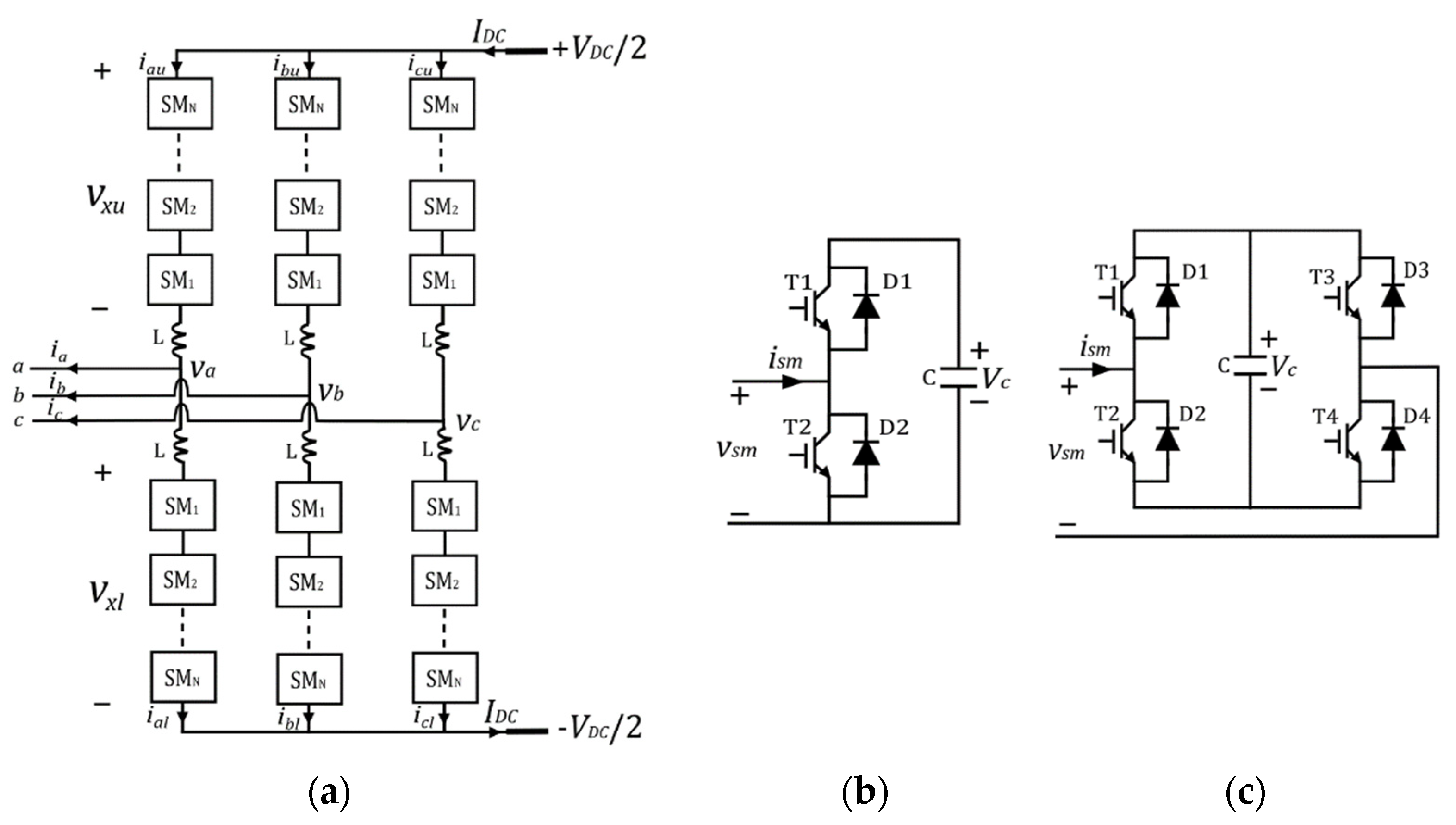

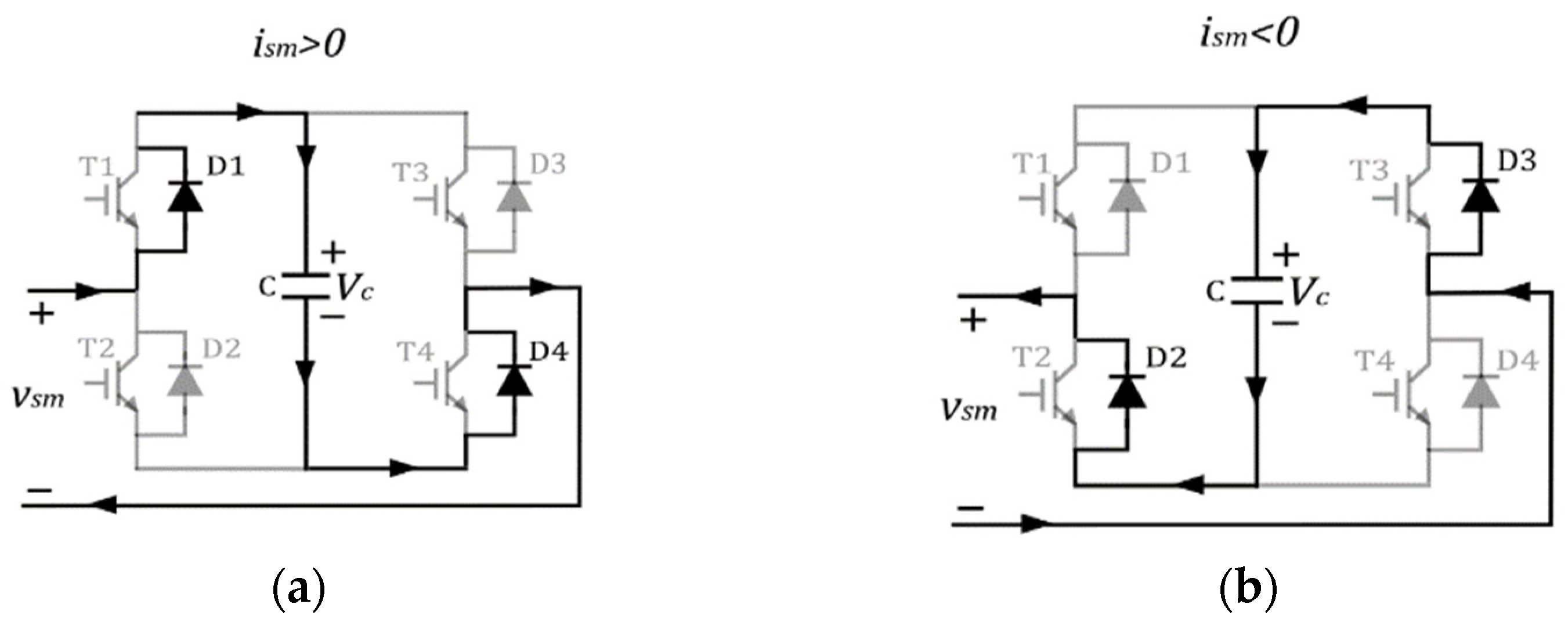

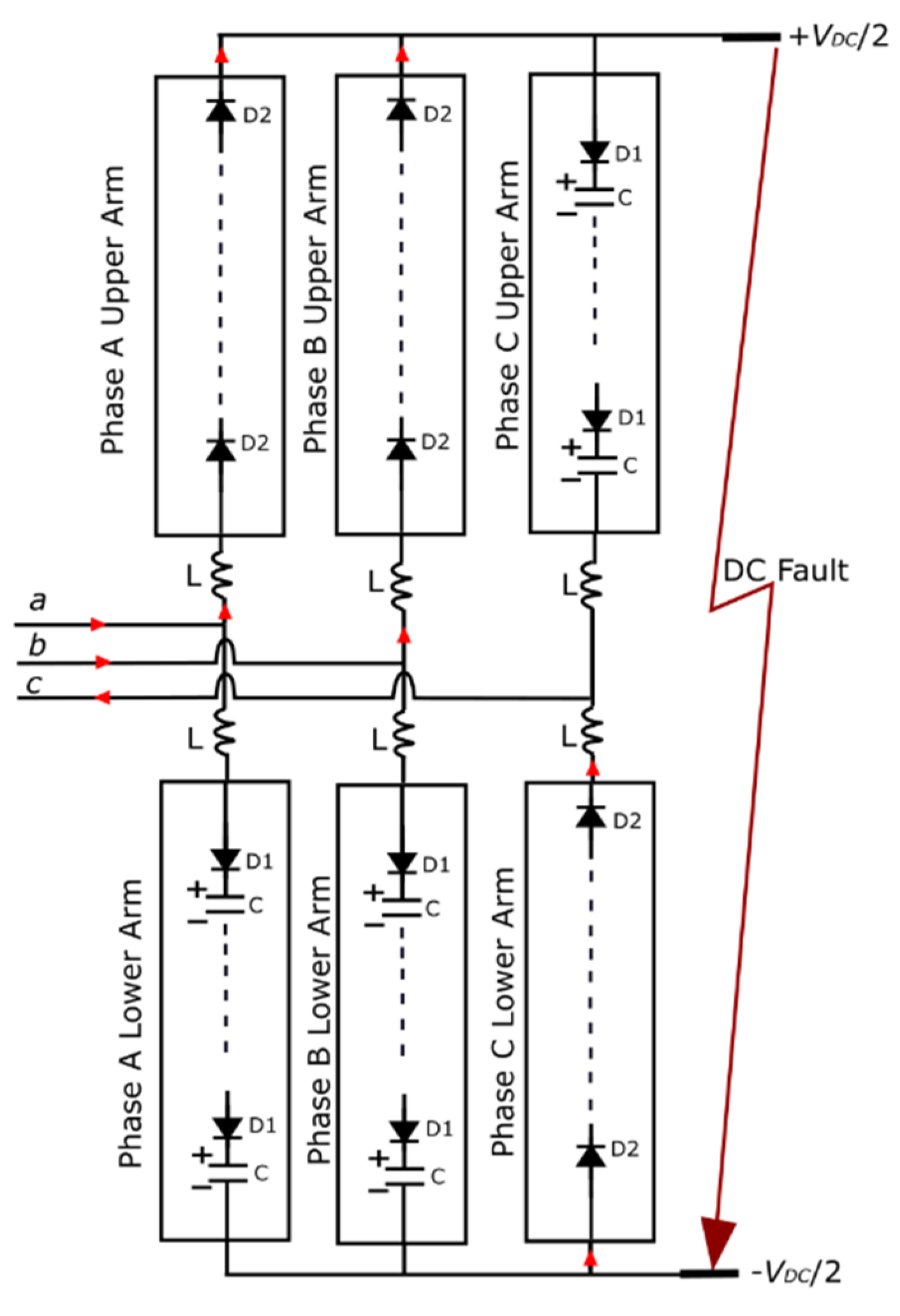
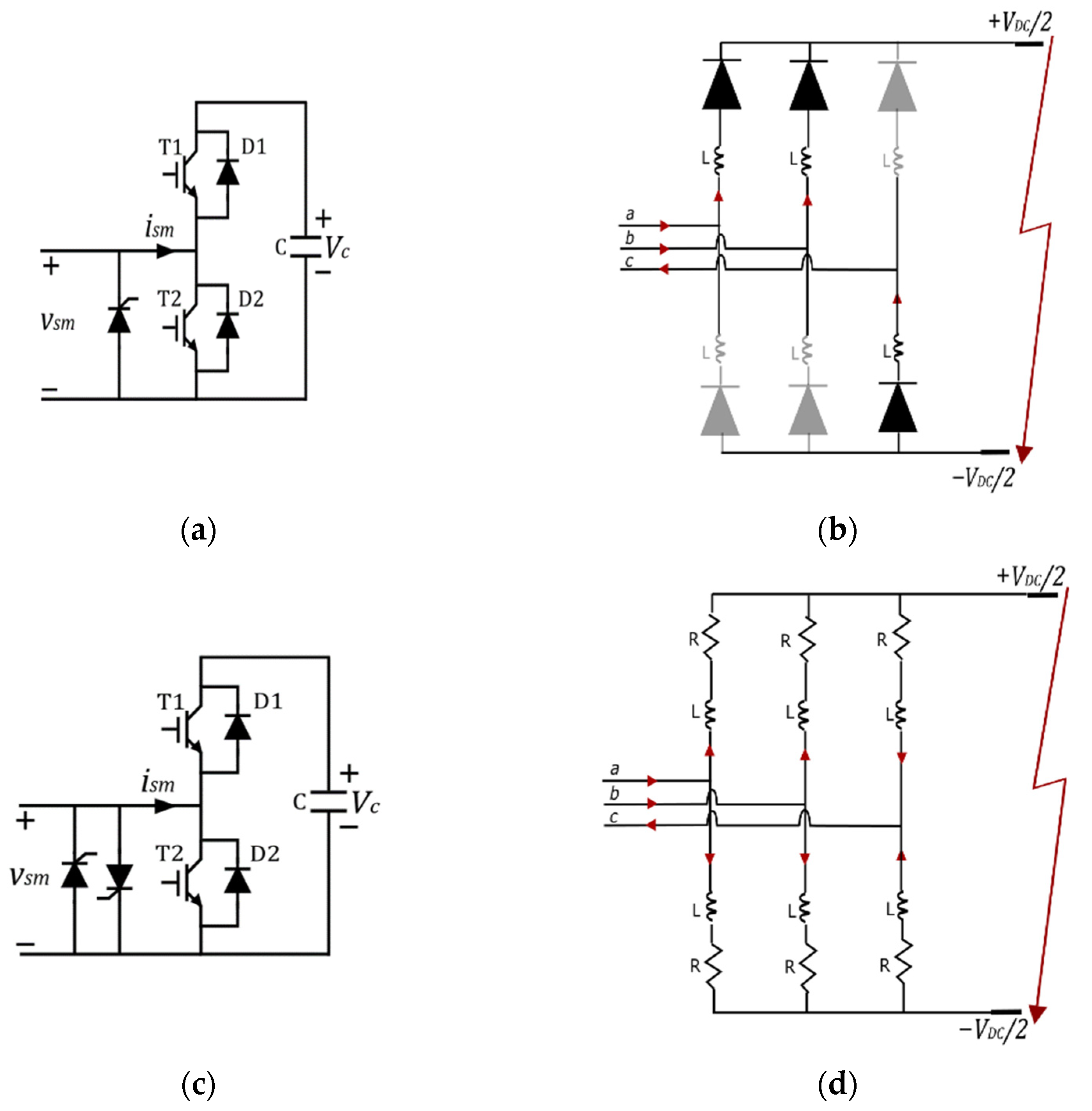
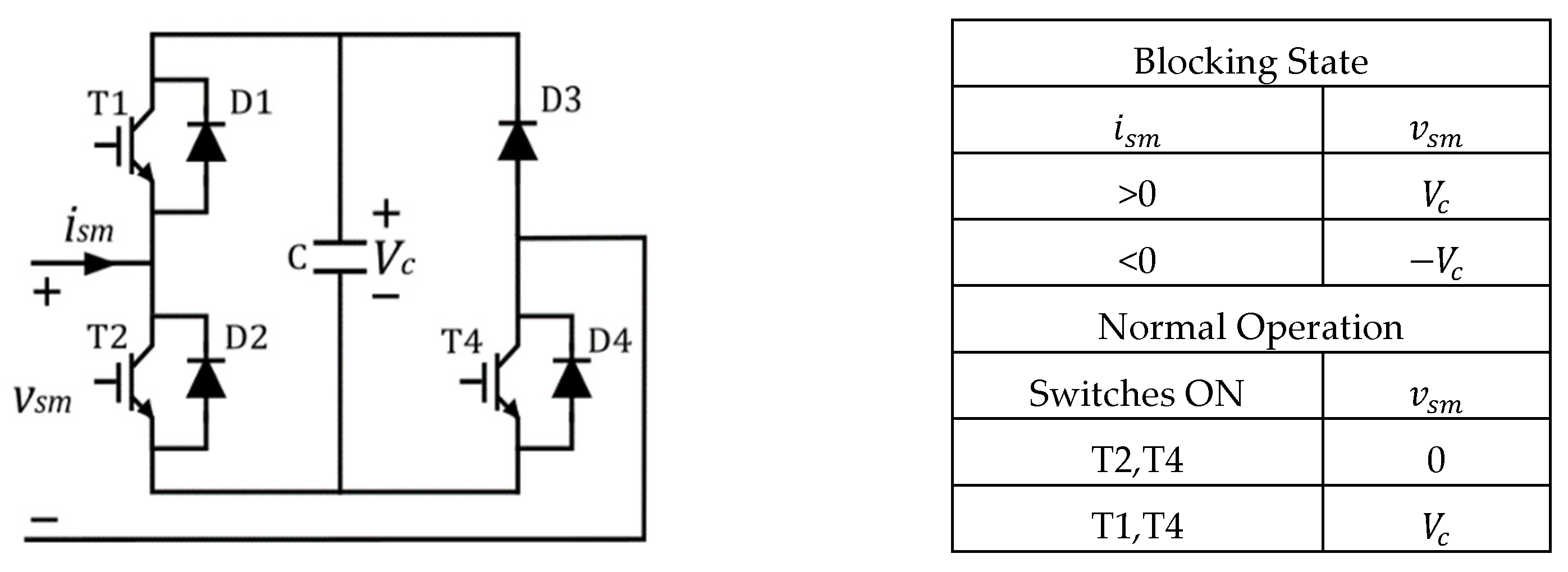
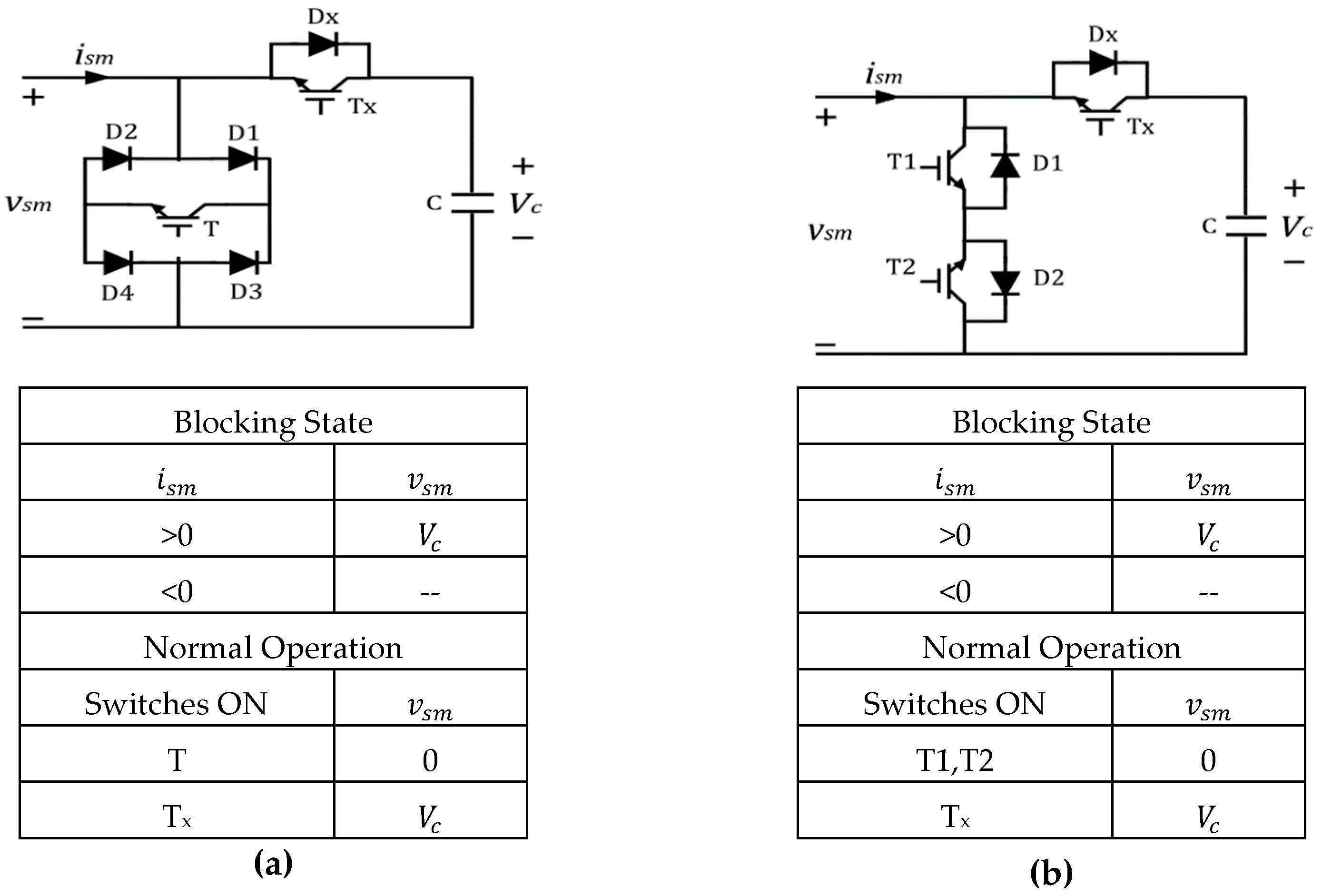
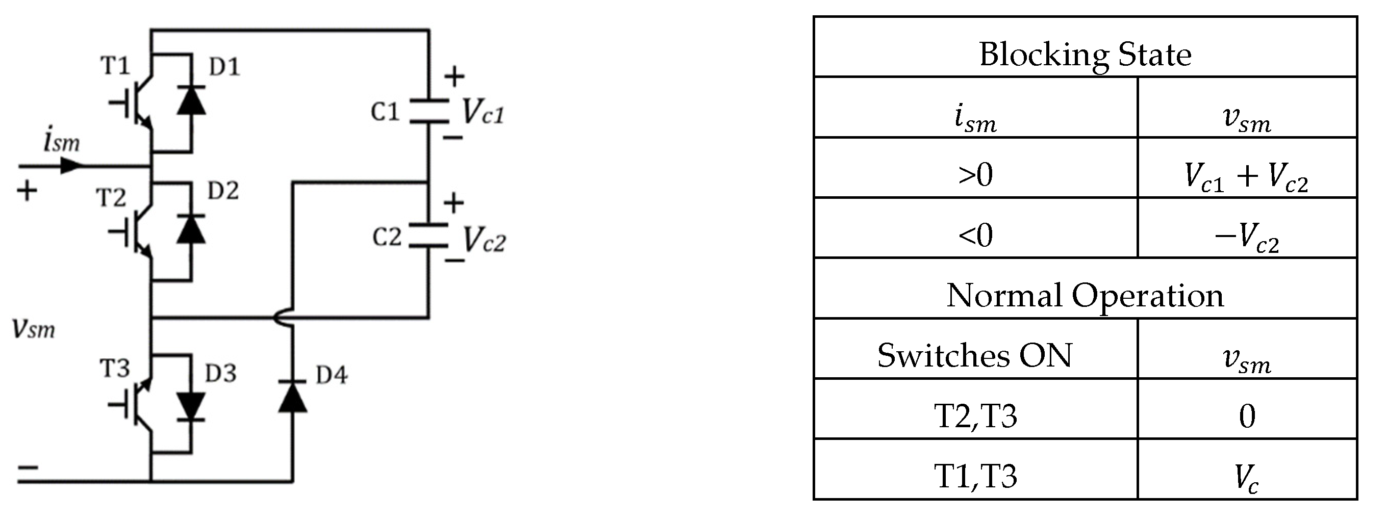
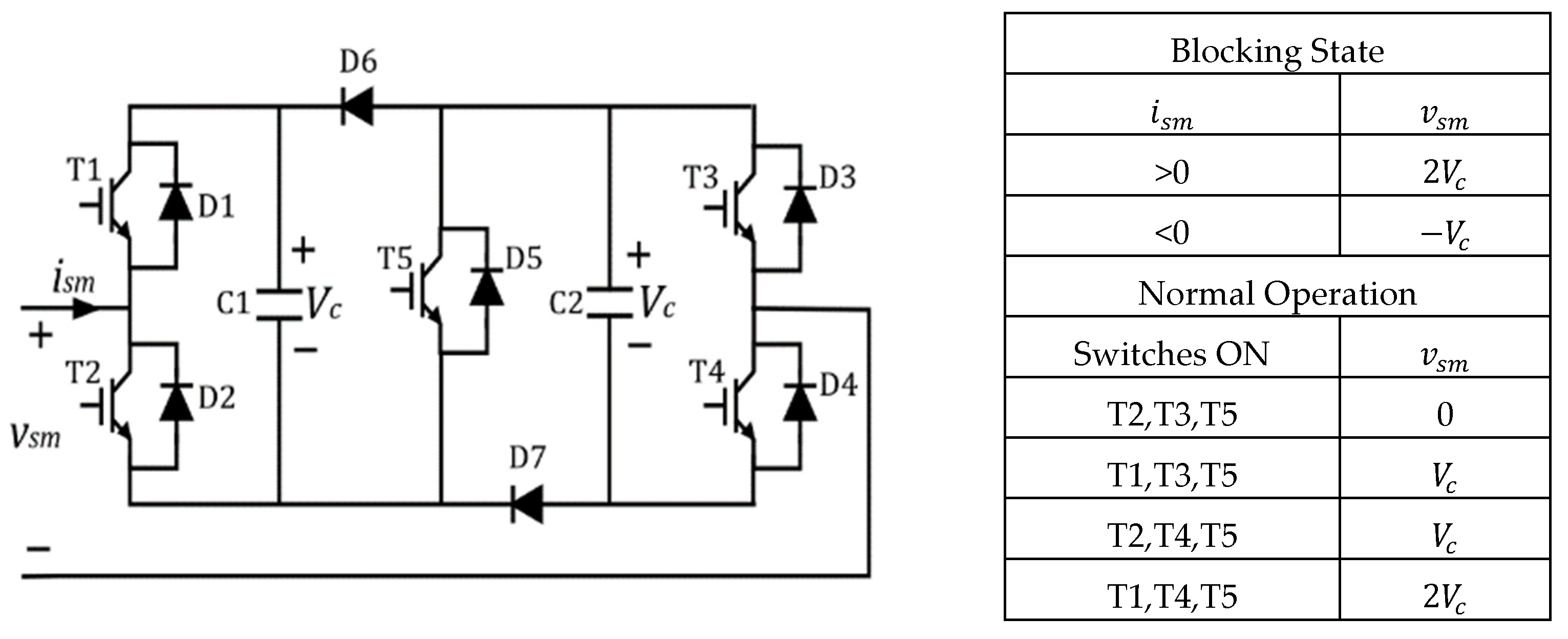
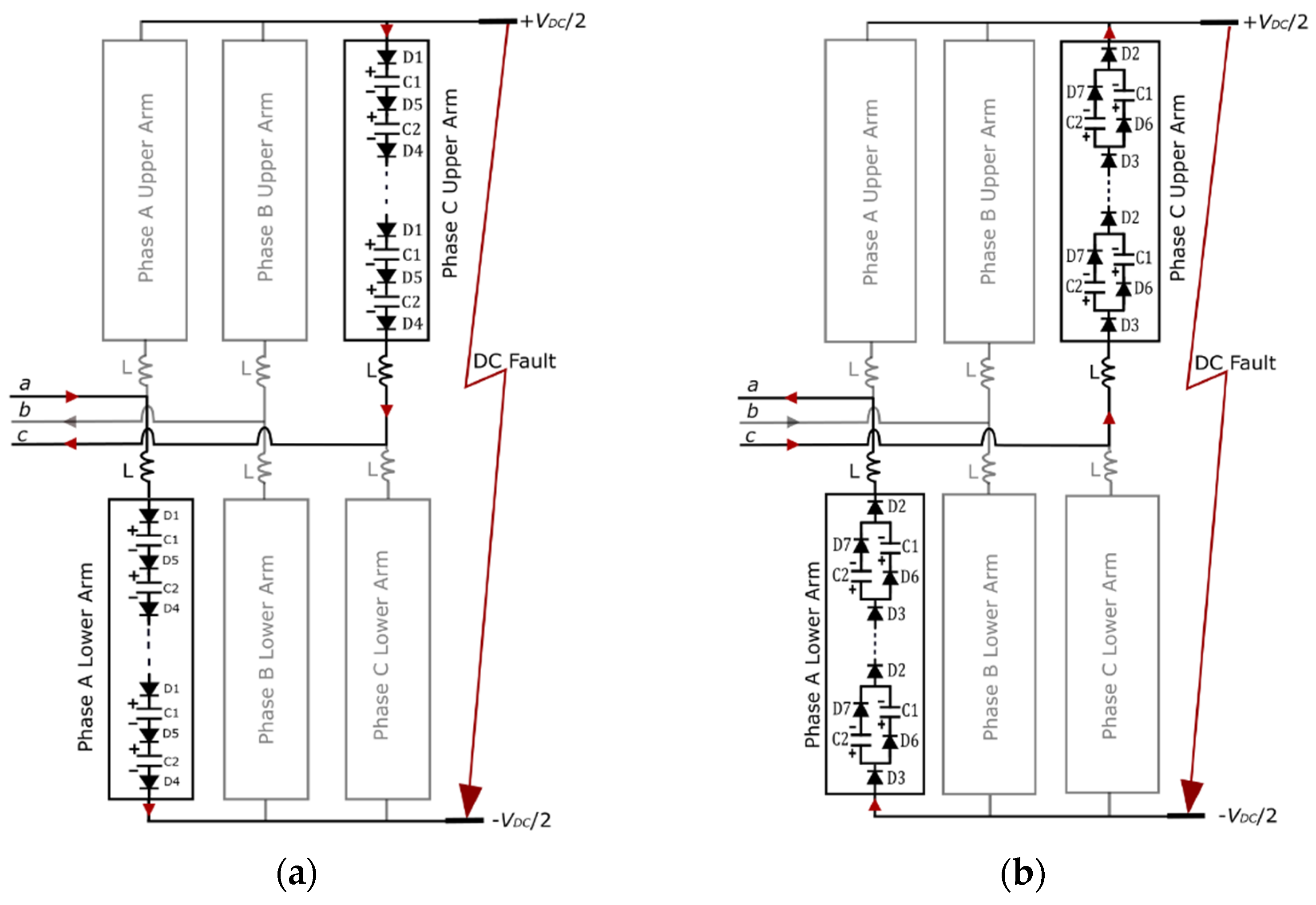
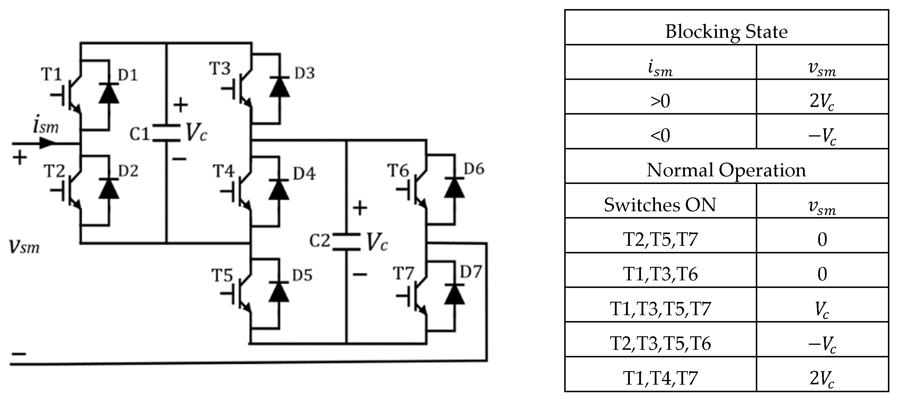
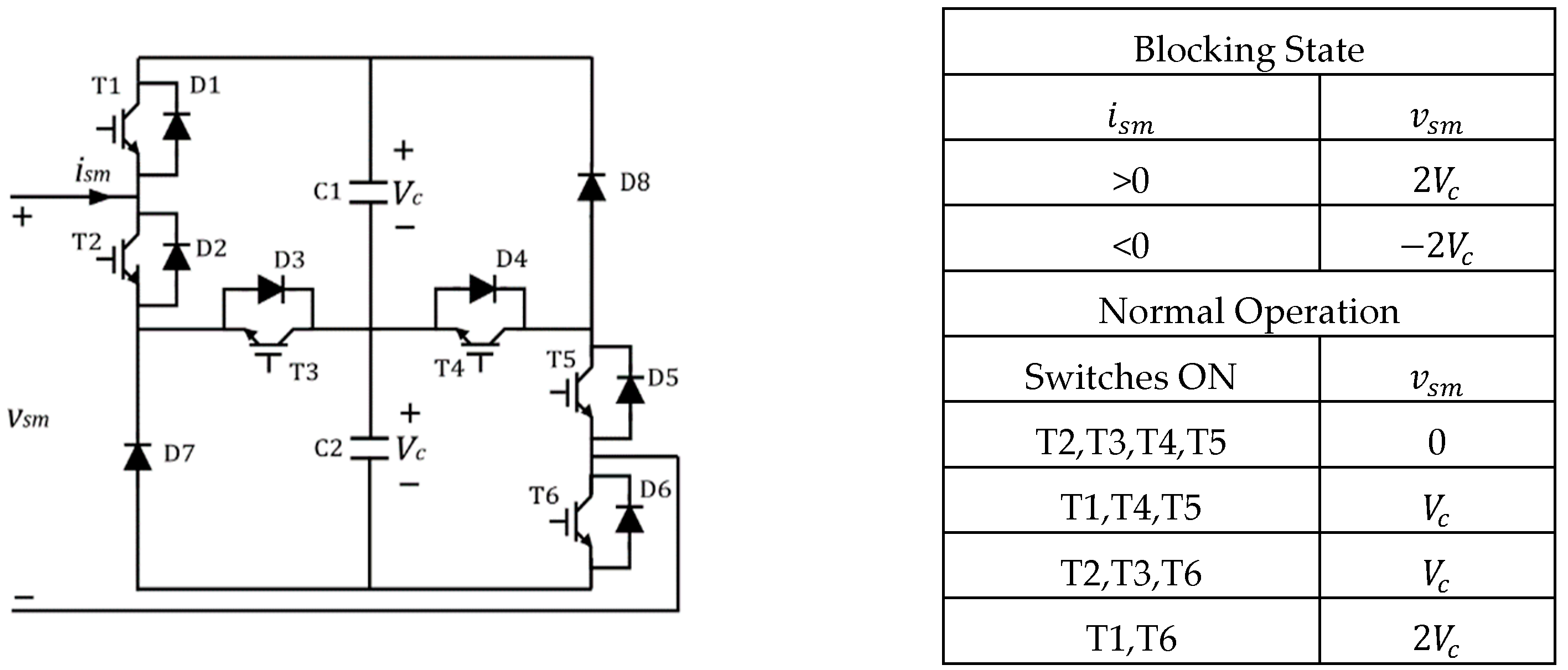
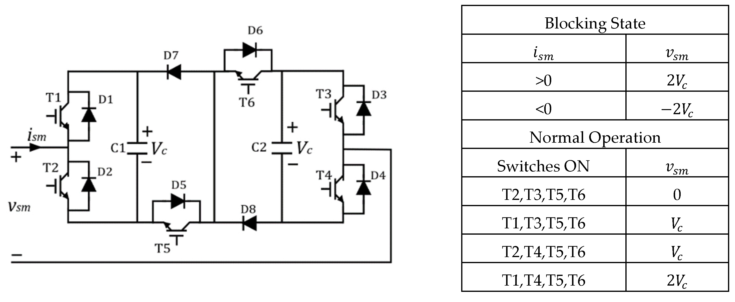
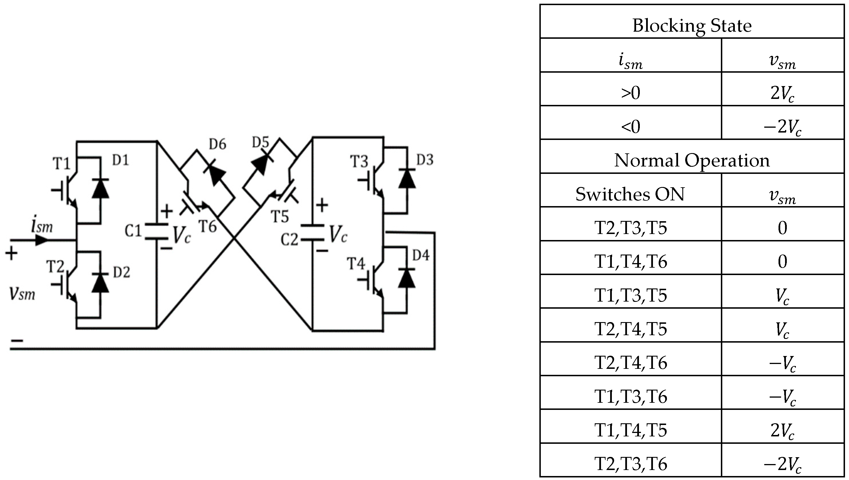
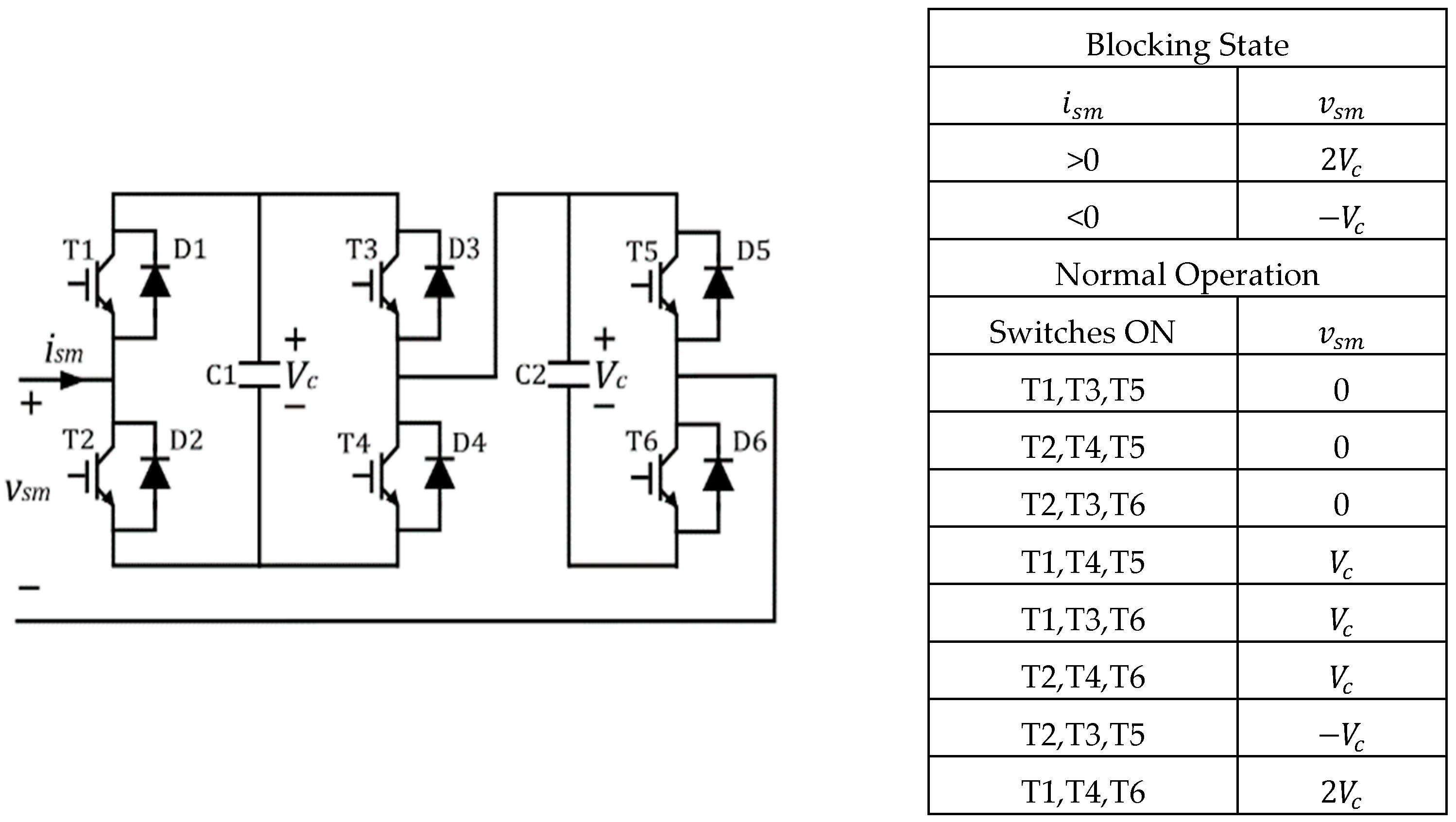
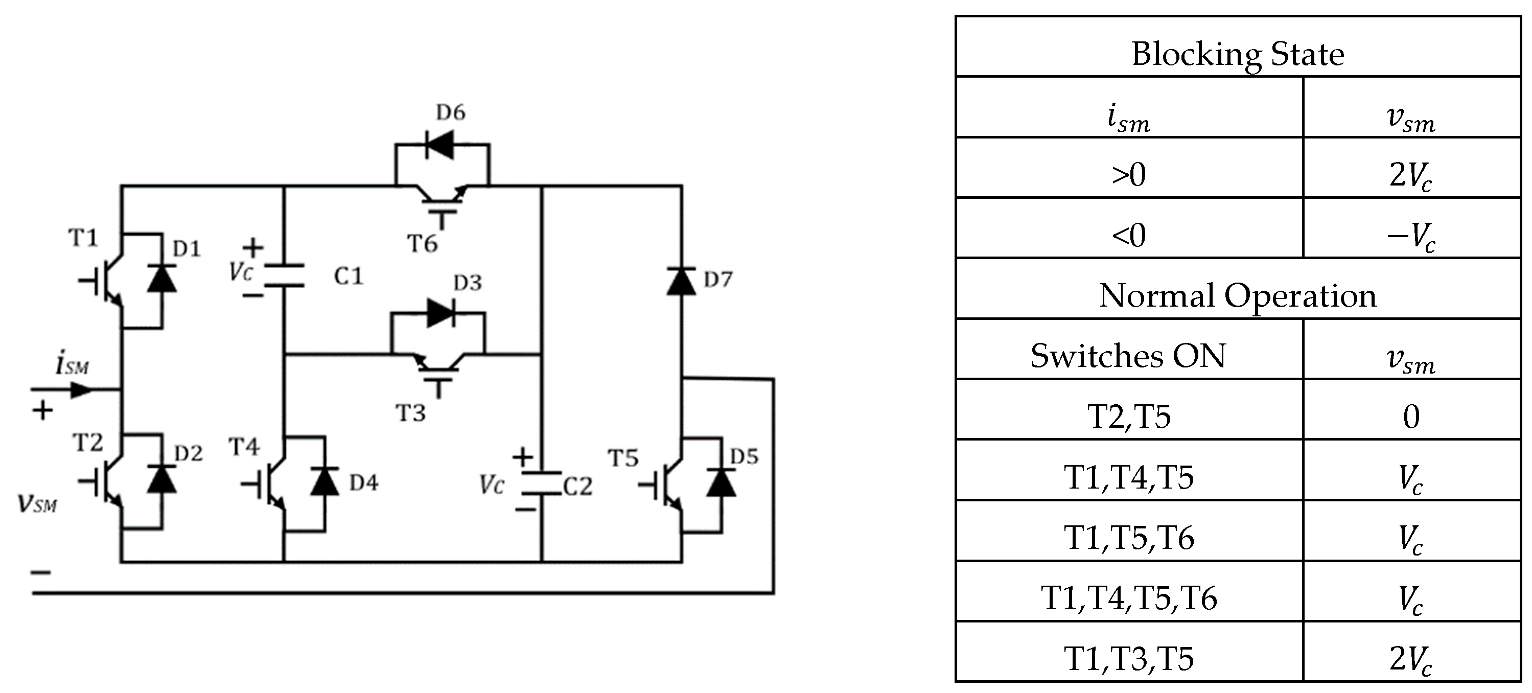
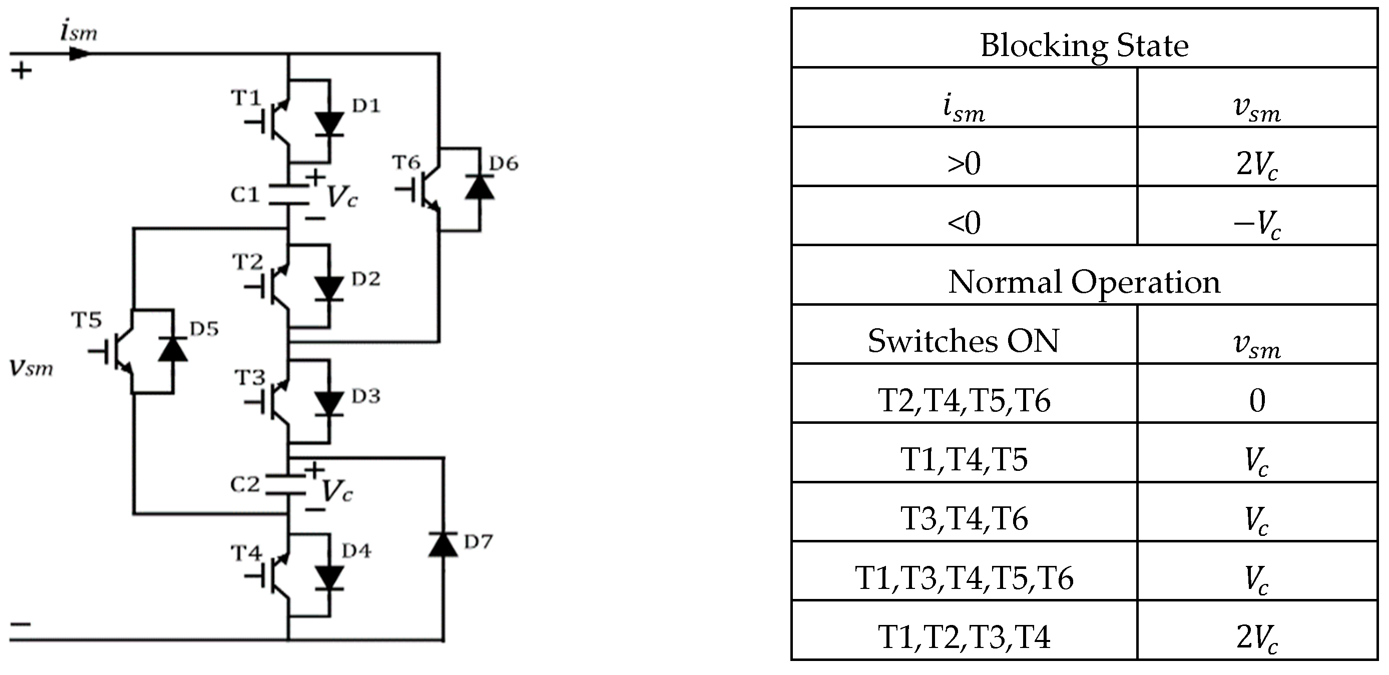

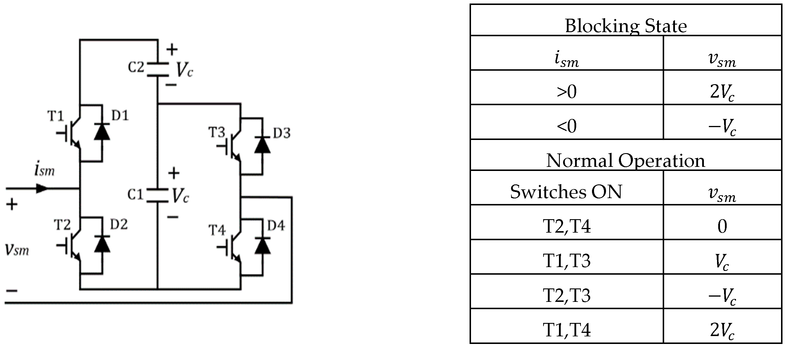
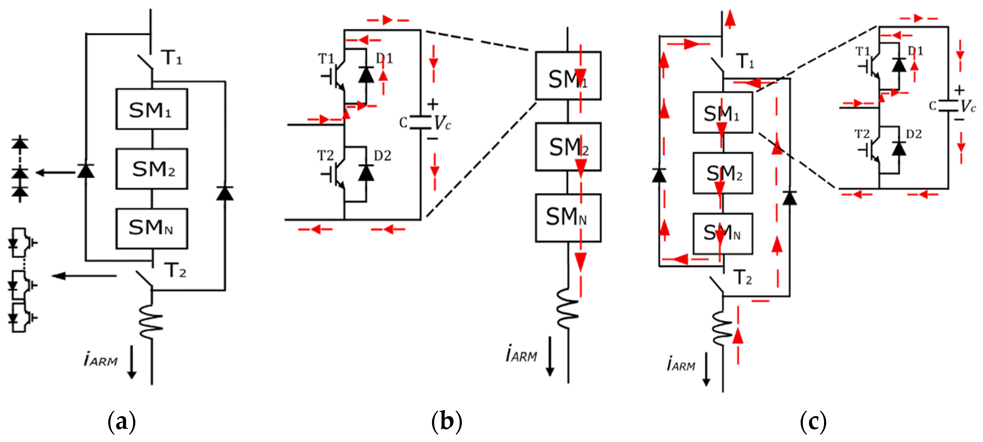


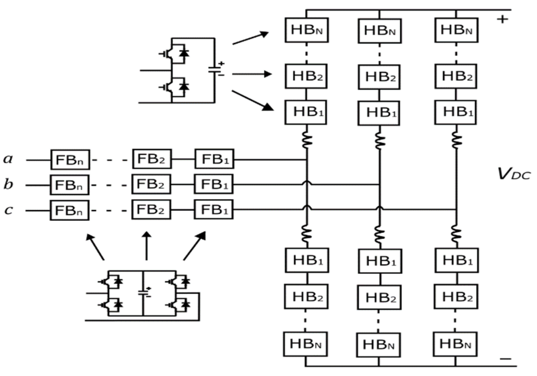
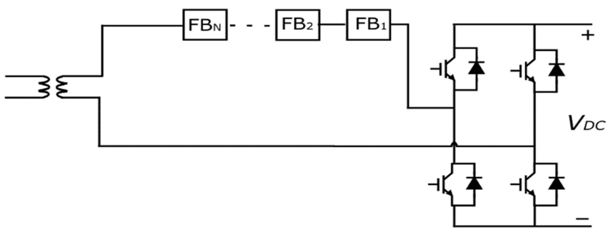

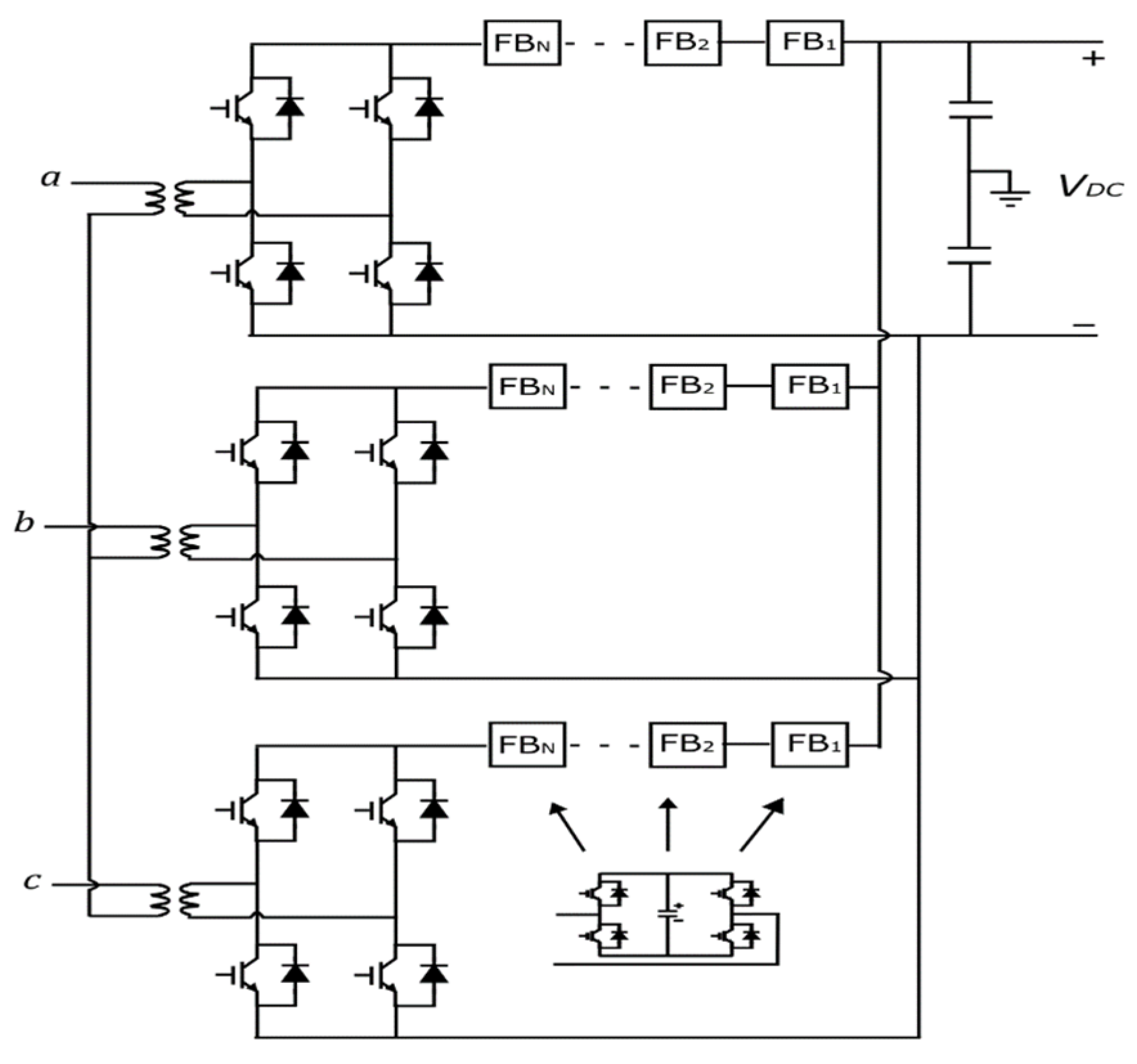
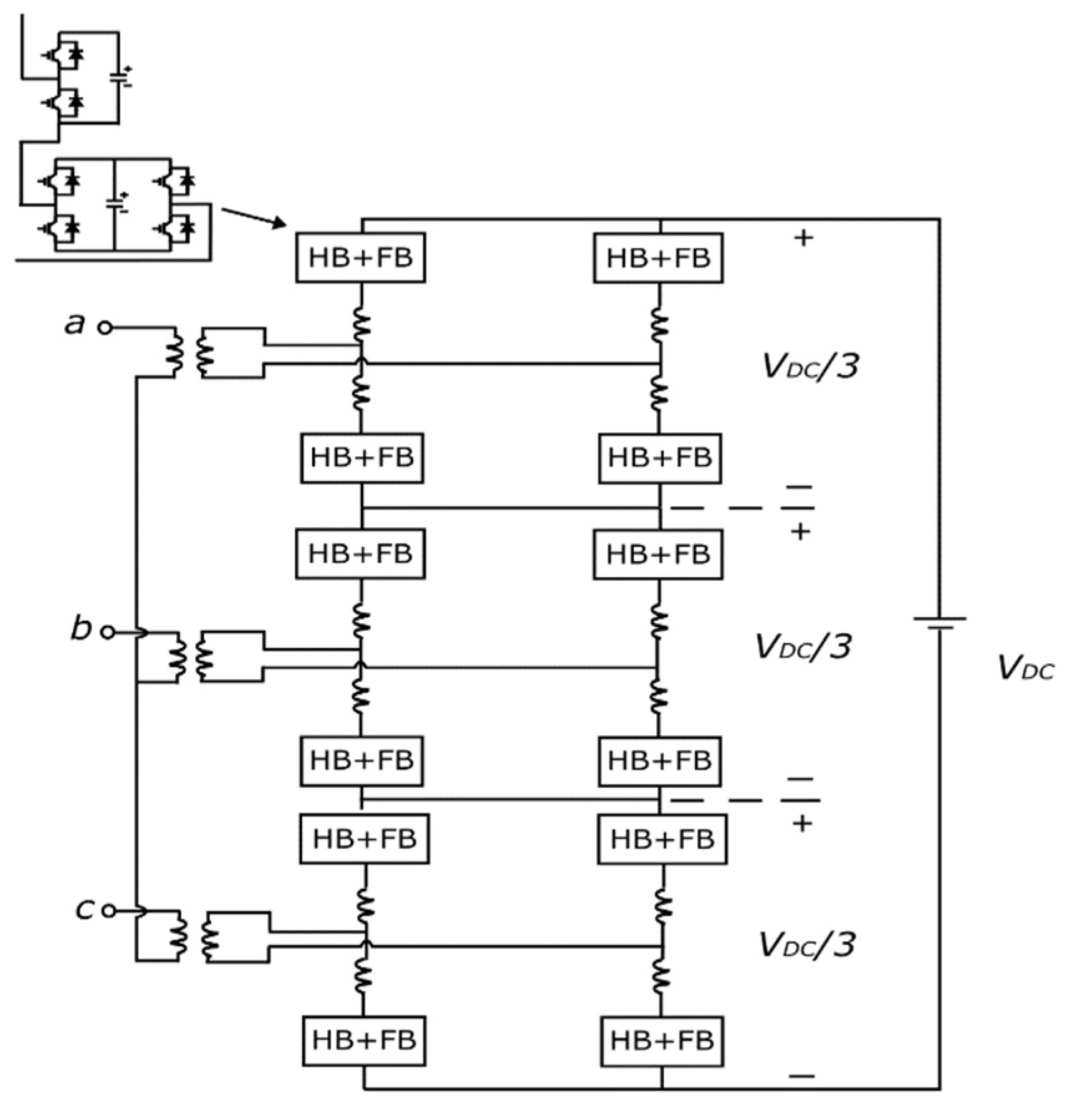
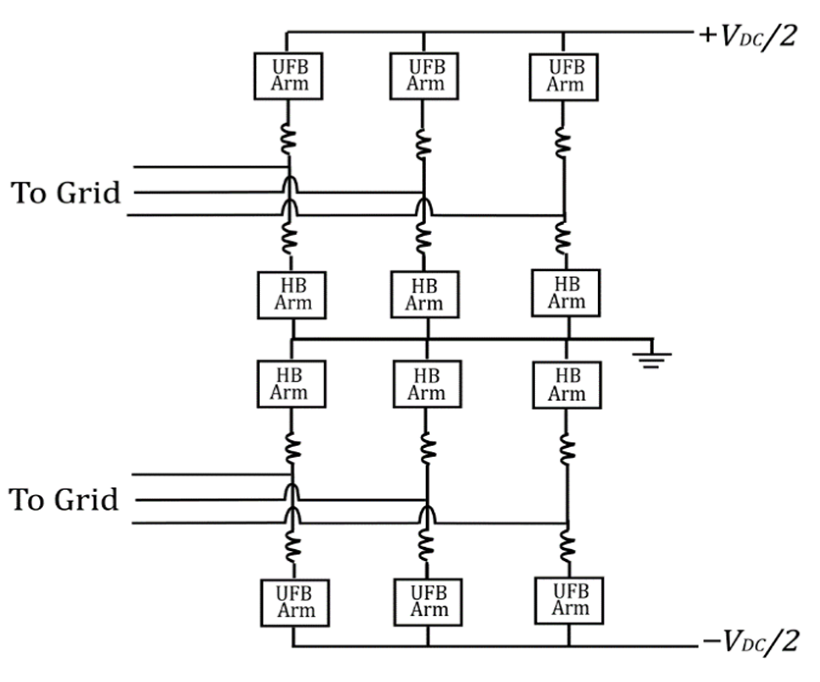
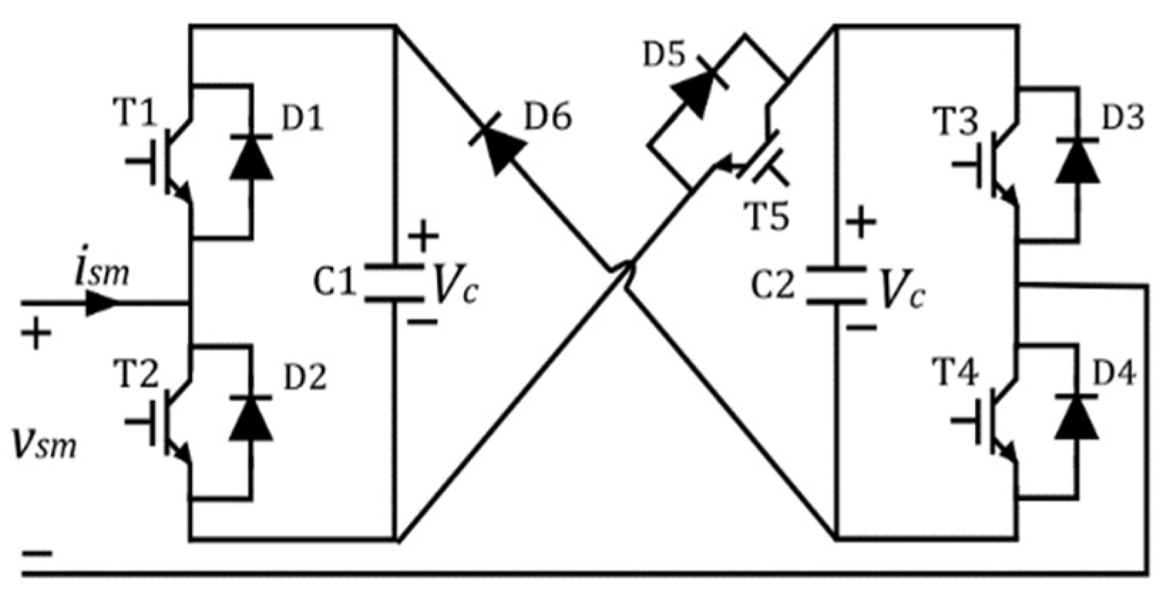
Publisher’s Note: MDPI stays neutral with regard to jurisdictional claims in published maps and institutional affiliations. |
© 2022 by the authors. Licensee MDPI, Basel, Switzerland. This article is an open access article distributed under the terms and conditions of the Creative Commons Attribution (CC BY) license (https://creativecommons.org/licenses/by/4.0/).