Abstract
As a widely-used method of digging roadways in China, gob-side entry driving features specific advantages, such as a high recovery rate and good isolation effects. However, under the condition of hard overburden, the excessive bearing pressure of small coal pillars will easily cause serious internal damage in the coal and the run-through of the plastic zone, leading to harmful gas leakage in the goaf. Therefore, based on the engineering background of small coal pillars in the 18506 working face of Xiqu Coal Mine, this paper comprehensively adopts theoretical analysis, numerical simulation, industrial tests, and other methods, analyzes the evolution mechanism of isolated bearing and plastic fracture areas of small coal pillar under hard overburden, studies the influence law of hard overburden cutting parameters on the isolation and stability of small coal pillars, and puts forward the technology of actively cutting the top to weaken the stress concentration of coal pillars under hard overburden. With the reasonable cutting parameters determined, the controllable mechanism of hydraulic fracturing cutting under hard overburden further revealed, and the hydraulic fracturing cutting technology with “controllable cutting orientation of hydraulic fracturing with local stress field intervention” formed as the basic core, the stress situation on the roof is improved, realizing the stability control of the coal pillars for the roadway protection, and avoiding gas leakage and other disasters caused by small coal pillar destruction.
1. Introduction
The increase in the mining of coal resources brings rising tensions to the Chinese resource situation. The roadway protection technology regarding small coal pillars in gob-side entry driving has been gradually adopted by more and more mines, with the width of coal pillars reduced from the original 30~40 m to 5~8 m, which not only greatly improves the coal recovery rate, but also prevents the stress outburst caused by the traditional wide coal pillars [1,2,3,4]. However, various types of problems caused by small coal pillar mines under the condition of a hard roof are becoming more and more serious due to the large internal bearing deformation of small coal pillars, the run-through of the plastic zone, and the poor isolation effect caused by the long hanging hard roof, leading to secondary disasters, such as harmful gas leakage in the goaf [5,6,7,8]. Therefore, the adoption and popularization of roof cutting and pressure relief technology have become an important direction for the development of gob-side entry driving with small coal pillars. At present, the commonly used roof cutting technologies can be mainly divided into blasting roof cutting and hydraulic fracturing roof cutting [9,10].
The existence of a hard hanging roof is the key to the deformation and failure of small coal pillars in gob-side entry driving. Wang et al. [11] analyzed the stress distribution law of coal pillars in the adjacent roadway under the condition of a hard hanging roof, and put forward that a hard hanging roof is the main cause of rock burst. Zha et al. [12] analyzed the influence of different fracture positions of a hard roof on the overlying load of small coal pillars. Du et al. [13] studied the evolution characteristics of the overlying strata structure in the gob-side entry mining process, and the increase in the hanging roof length easily leads to the stress concentration of coal pillars in the roadway. Yang et al. [14] summarized the evolution law of the roof caving structure with different cantilever lengths, and short cantilever beams are more easily form stable structures. Yu et al. [15,16] studied the force relationship of the block in the process of hard roof breaking and the impact effect of backward roof collapse. Li et al. [17] established the mechanical model of small coal pillars in gob-side entry driving, and deduced the width of the “internal stress field” of coal pillar.
Roof cutting and pressure relief can actively cut off the upper roof, improving the surrounding rock stress environment. Based on the short-arm beam theory, He et al. [18,19] proposed cutting off the stress transmission path between the roadway and the working face by prefabricating the seam structure plane of the roof so as to improve the structural form of the roof strata. Guo et al. [20] analyzed the action mechanism of roof cutting and pressure relief on the roadway under the condition of a thick and hard basic roof, simulating and testing the rock pressure law of the surrounding rock under different roof cutting heights, and the results showed that the pressure relief effect was the most obvious when the basic roof was cut off by a slit. Su et al. [21] studied the movement law of the overlying strata structure after roof cutting in the adjacent roadway using a similar model, and found that the deformation of the roadway decreased by 50%, and the stress of coal pillar decreased by 19% after roof cutting. Wang et al. [22] cut off the roof in time using deep-hole presplitting blasting, which effectively controlled the problem of roof weighting. Zhang et al. [23] revealed the mechanism of roof cutting, pressure relief, and allowing small coal pillars to protect the roadway, and realized the active regulation of the surrounding rock pressure of the roadway.
By artificially determining the fracture position and fracture form of the roof, directional topping can actively control the expansion direction of the slit, achieving a better topping effect. Hou et al. [24] proposed to prefabricate weak structural planes in the rock strata, change the stress transmission direction, and control the development of blasting cracks along the set direction. He et al. [25] put forward the directional presplitting technology, with two-way shaped charge tension blasting as its core, and controlled the fracture orientation by the shaped charge direction of the explosive. Qin et al. [26] carried out directional presplitting blasting for a hard roof in a thin coal seam, which effectively controlled the position of the roof fracture line and the development direction of the cracks. Gao et al. [27] put forward the technology of directional tension blasting with top cutting and pressure relief, which guided the explosion wave to expand in the specified direction by prefabricated guide cracks of shaped energy flow. Zhang et al. [28] proposed the use of a slotted charge to change the propagation direction of the hole crack to realize directional roof fracture blasting. However, when the gob with high gas concentration is on the side of roof cutting, blasting roof cutting will easily lead to the run-through of the plastic zone and gob and gas leakage, causing disasters such as gas explosions [29].
As a new topping technology after blasting topping, hydraulic fracturing topping can achieve more efficient, safe, and economical topping, solving a series of problems such as a hard roof, rock burst, coal and gas outburst, weakening of hard top coal, etc. However, hydraulic fracturing topping technology includes the problem that the expansion direction of hydraulic fractures is difficult to control [30]. Therefore, some scholars have put forward methods [31,32,33] such as blade cutting, high-pressure water jet cutting, abrasive jet cutting, etc., to control the hydraulic fracturing direction by prefabricating pilot joints. However, the limited influence range and limited pilot effect of these methods lead to the unsatisfactory control effect of the fracture propagation direction. On the other hand, hydraulic fracturing is affected by in situ stress. Based on the fact that the propagation directions of hydraulic fractures are different under different in situ stress environments, the difficulty of fracture guidance is further aggravated. Therefore, with the return air highway of the 18506 working face in the Xiqu Coal Mine taken as the research object, this paper simulated the fracture propagation mechanism of hydraulic fracturing in different stress fields under hard overburden conditions based on XFEM, providing the theoretical guidance for the engineering site. Directional hydraulic fracturing technology, with the goal of changing the local stress field environment to control fracture turning, is proposed, which provides reference significance for safe mining in mines under similar conditions.
2. Deformation and Failure Characteristics of the Surrounding Rock in Gob-Side Entry with Small Coal Pillars
2.1. Project Overview
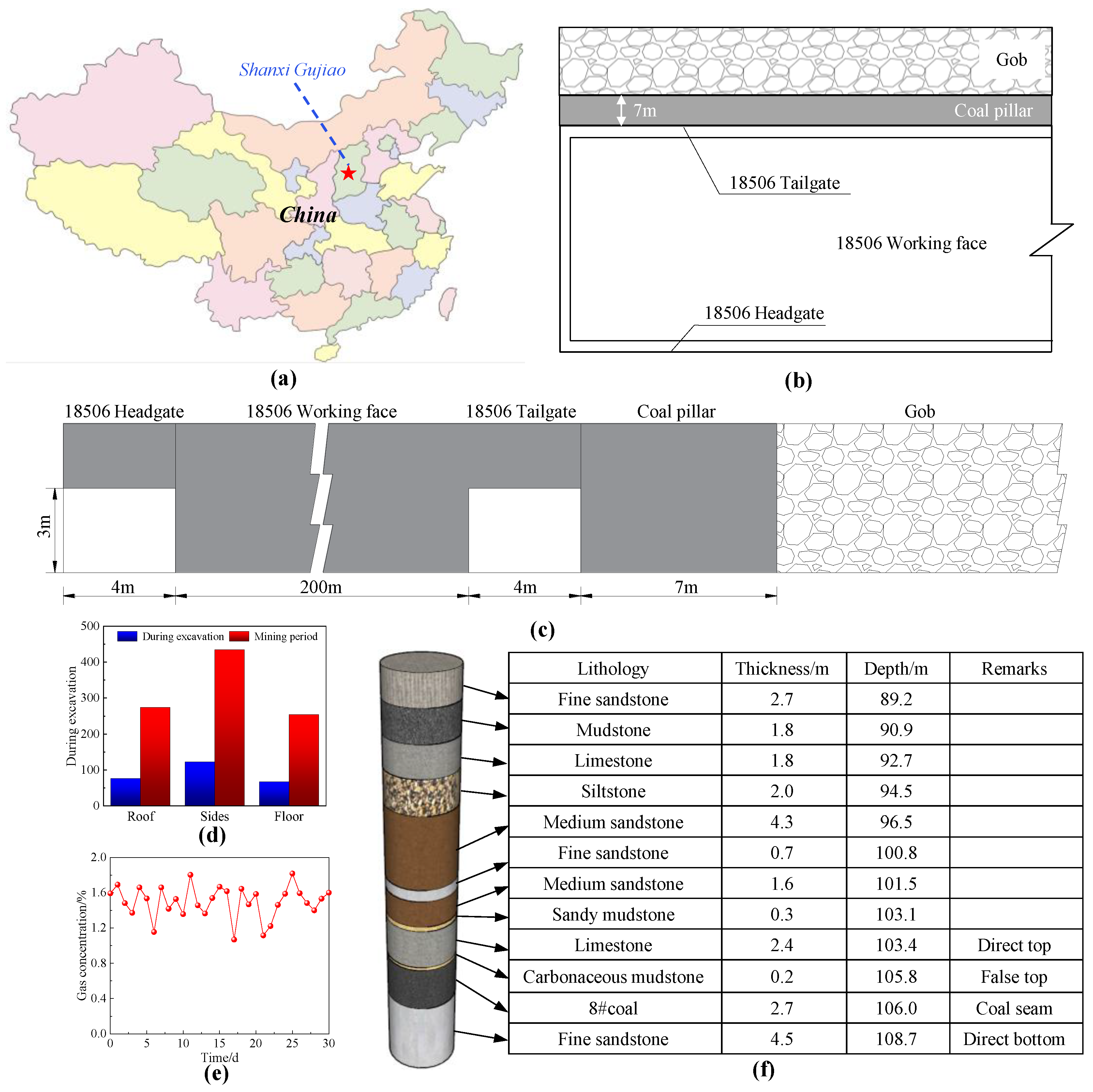
With the mining level of +983 m, the Xiqu Coal Mine now has a No. 8 coal seam mined using fully-mechanized coal winning technology. The gas level is low, and the spontaneous combustion tendency of the coal seam is low. The inclined length of the 18506 working face to be mined is about 200 m, the strike length is about 450 m, the average thickness of coal seam is 2.7 m, and the average buried depth is 106 m. There is a thin carbonaceous mudstone layer of about 0.2 m above the No. 8 coal seam, with 2.4 m limestone on the direct roof and 4.5 m fine sandstone on the direct bottom. The return air lane of the 18506 working face has a rectangular cross section, with a clear width of 4 m and a clear height of 3 m. The goaf of the old kiln is located on the east side of the coal pillar in the return air lane of the 18506 working face, and a large amount of harmful gases are accumulated inside. At the same time, the width of the coal pillar between the goaf of the old kiln and the return air lane of the 18506 working face is only 7 m. During the mining period, the coal pillar was seriously damaged, and the harmful gas leaked out of the goaf of the old kiln, which caused the gas concentration in the return air lane of the 18506 working face to be too high, affecting the safety of mine production. The details of the 18506 working face are shown in Figure 1.
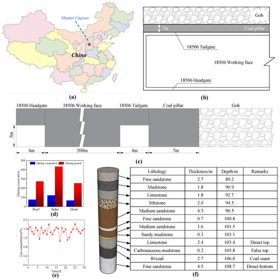
Figure 1.
Overview of Xiqu Coal Mine: (a) mine location; (b) layout of working face; (c) section view; (d) roadway deformation; (e) gas concentration; (f) section view.
2.2. Theoretical Analysis of Coal Pillar Stability in Roadway Protection under the Condition of Hard Overburden
According to the theory of elastic–plastic mechanics, the mechanical model of the coal pillar in gob-side entry protection is established [34,35,36], as shown in Figure 2. The whole coal pillar can be divided into three areas: ① Area I: the plastic fracture area of the upper working face. This part of coal pillar is affected by the goaf of the old kiln, and the whole coal pillar is in a plastic state, with low bearing capacity and a width of x1. ② Area II: the isolated bearing area. This part of the coal pillar is less affected by disturbance, and the whole part is in an elastic state, with strong stability, good bearing capacity, and almost no damage, which can well isolate the gas and water in the goaf of the old kiln; its width is x2. ③ Area III: the bolt support area of this working face. This part of the coal pillar is supported by the bolt in the return air lane of the 18506 working face, and it has a certain stability, with a width of x3.
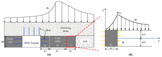
Figure 2.
Mechanical model of coal pillar in roadway protection: (a) mechanical model of roadway pillar; (b) plastic fracture zone.
Zone I of the coal pillar in the roadway is in a plastic failure state, and the interface between zone I of the plastic failure state and zone II of the stable state is in a limited equilibrium state. The equilibrium equation is:
The main function of the coal pillar in roadway protection is to protect the roadway and to isolate harmful gas and mine water at the goaf side. It is of great importance for guaranteeing mine safety production to ensure the stability of the coal pillar in roadway protection. The width of the coal pillar in roadway:
In the Formula (2), L is the width of the coal pillar for roadway protection m; x1 is the width of the plastic fracture zone on the coal pillar of roadway protection m; x2 is the width of the isolation bearing area inside the roadway pillar m; x3 is the length of the bolt support in this working face, which is 1.8 m.
According to the limit equilibrium theory, the width of the plastic fracture zone of upper working face is obtained:
In Formula (3), m is the thickness of the coal seam, taking 2.7 m; γ is the weight of overlying strata, taking 25 kN/m3; H is the buried depth of the roadway, taking 106 m; C0 is the cohesion of the coal seam section, taking 3 MPa; p is the coal support resistance, taking 0.4 MPa; K is the stress concentration coefficient, taking 1.2; λ is the lateral pressure coefficient, λ = μ/(1 − μ), taking 0.18, μ is Poisson’s ratio; and φ is the internal friction angle of coal seam, taking 34.
The isolated bearing area of the coal pillar in roadway is calculated according to the following formula:
In Formula (4), k is the safety factor of the minimum width of the coal pillar, which is 1.15~1.45.
Substituting the above parameters into Formula (2), we obtain L = 10.2 m.
According to the above theoretical analysis, increasing the width of the coal pillar can ensure the stability of the coal pillar and improve its isolation performance. In order to ensure a good isolation effect, the roadway protection coal pillar with a width of more than 10.2 m should be adopted. However, since the width of the coal pillar in roadway protection in the 18506 working face is fixed at 7 m, the same effect can be achieved by reducing the pressure of overlying strata on the coal pillar in roadway protection.
2.3. Bearing Deformation Characteristics of Coal Pillar in Roadway Protection under the Condition of Hard Overburden
2.3.1. Establishment and Correction of the Model
- (1)
- Model establishment
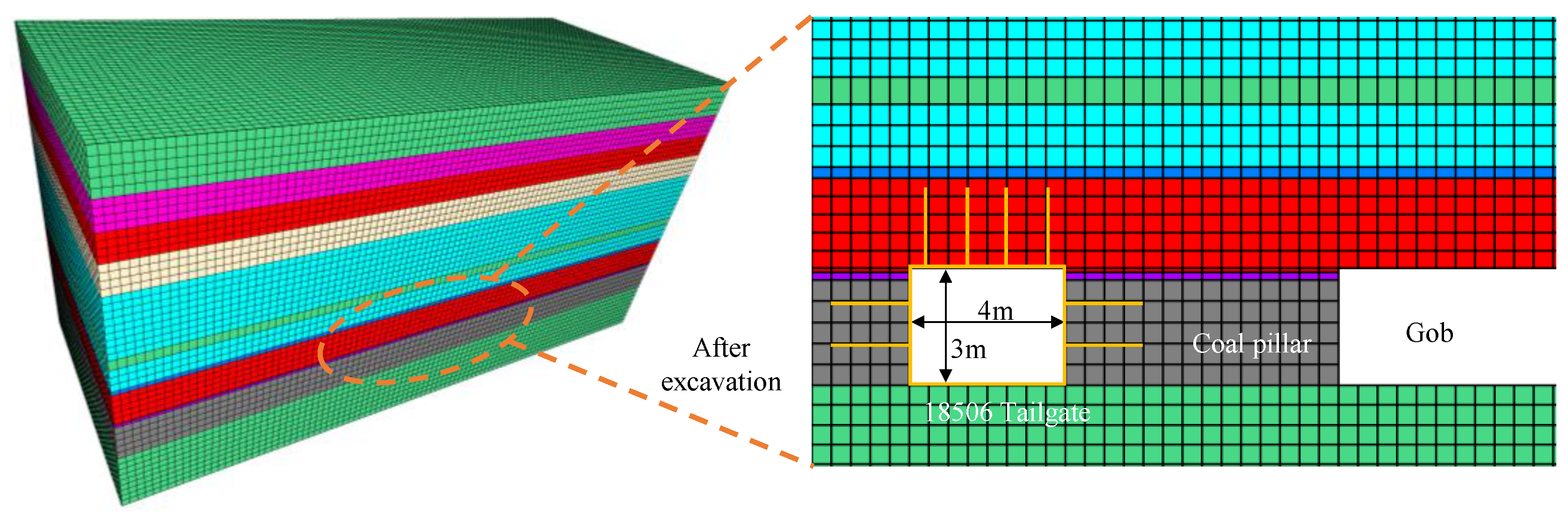
With the help of the finite element software FLAC3D 6.0, a numerical calculation model is established according to the field conditions, as shown in Figure 3. The Mohr–Coulomb model is adopted, with the length × width × height = 50 m × 20 m × 25 m, and the section width × height = 4 m × 3 m of the return air roadway in the 18506 working face, with a total of 208,000 units and 219,473 nodes. The horizontal displacement in the lateral direction of the model and vertical displacement on the bottom of the model are limited. The top side of the model is the stress boundary, and a load of 2.6 MPa is applied to simulate the weight of overlying strata, with a lateral pressure coefficient of 1.2. To study the stability characteristics of the coal pillar in roadway protection under different widths, the width of the coal pillar in roadway protection is taken as 7 m, 9 m, 11 m, 13 m, and 15 m respectively. See Table 1 for the lithologic parameters used in the numerical model.
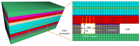
Figure 3.
Numerical calculation model.

Table 1.
Lithologic parameters used in numerical model.
- (2)
- Model correction
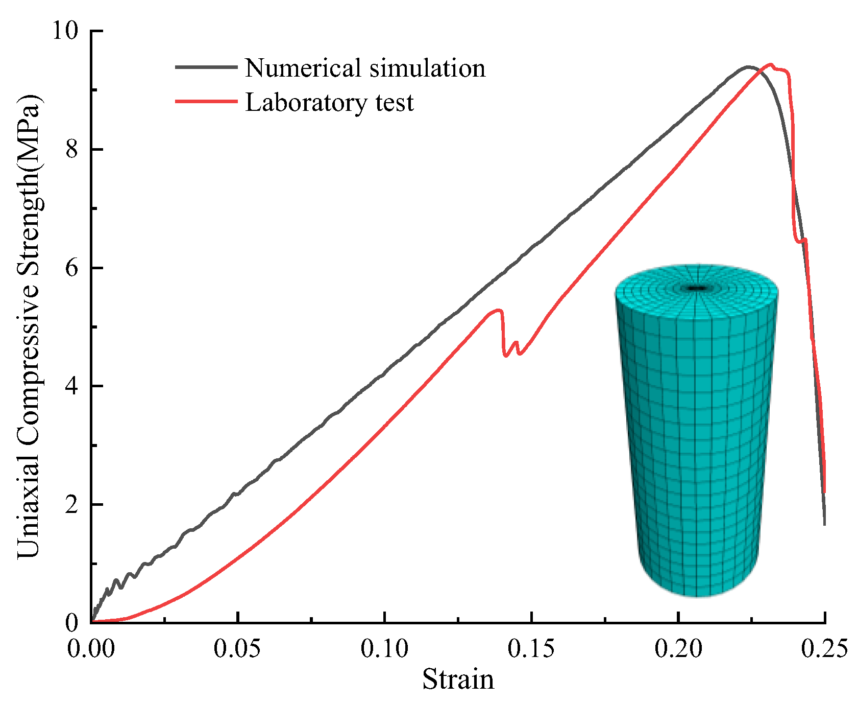
In order to ensure the accuracy of the coal seam mechanical parameters in the numerical calculation model, FLAC3D was used to establish a correction model with diameter × height = 5 m × 10 m, and the coal pillar was subjected to the uniaxial compression test, which was compared with the results of the laboratory uniaxial compression test [37,38]. The correction results are shown in Figure 4.

Figure 4.
Comparison of stress–strain curves between numerical model and laboratory tests.
2.3.2. Bearing Deformation Law of Coal Pillar in Roadway Protection under the Influence of Mining
- (1)
- Vertical stress distribution law of coal pillar in roadway protection
The nephogram of vertical stress distribution of coal pillars with different widths during mining is shown in Figure 5. It can be seen from Figure 5: ① When the width of the coal pillar in the roadway protection changes, the stress on the working face and the goaf has little influence, and the stress value is basically stable at 2~4 MPa; the internal stress of the coal pillar is obviously affected, and every change in coal pillar width can cause the internal stress to change by 2~5 MPa. ② With the increase in coal pillar width, the stress peak area gradually shifts from the middle of the coal pillar to the goaf side, the stress concentration range gradually decreases, and the stability of the coal pillar gradually improves.
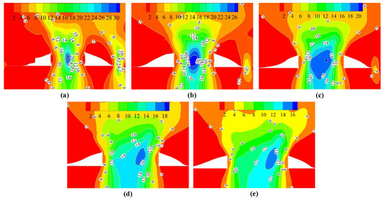
Figure 5.
Nephogram of vertical stress distribution of coal pillars with different widths during mining: (a) 7 m; (b) 9 m; (c) 11 m; (d) 13 m; (e) 15 m.
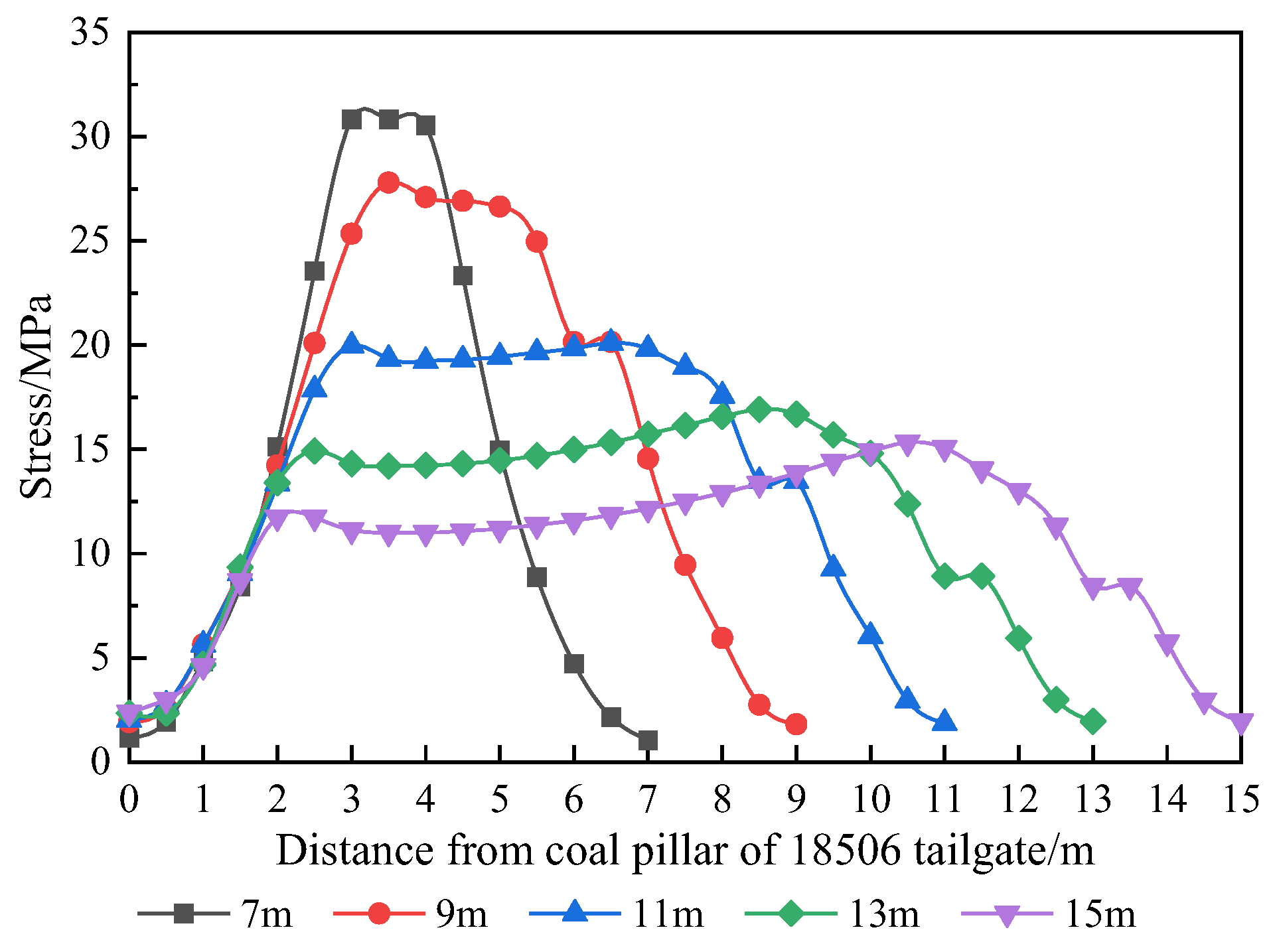
The vertical stress distribution curve of coal pillars with different widths during mining is shown in Figure 6. It can be seen from Figure 6: ① When the width of the coal pillar in the roadway protection is 7 m, the stress concentration occurs in the central position of the coal pillar, and the stress peak reaches 30.8 MPa. When the width of the coal pillar in the roadway is 9 m, the peak stress is 27.8 MPa, which is reduced by 9.7%. When the width of coal pillar in the roadway is 11 m, the stress peak value is 20.1 MPa, which is reduced by 34.7%. When the width of coal pillar in the roadway is increased to 13 m, the peak stress is 16.9 MPa, which is reduced by 45.1%. When the width of the coal pillar in the roadway protection reaches 15 m, the peak stress decreases to 15.3 MPa, which is only 49.6% of that at 7 m. ② When the width of the coal pillar in the roadway protection is narrow, the stress rises steeply, and the whole coal pillar is in a high stress state. When the width of the coal pillar in the roadway protection reaches 11 m, the upward trend of internal stress in the coal pillar gradually eases, with the internal stress of the coal pillar basically within 20 MPa.

Figure 6.
Vertical stress distribution curve of coal pillars with different widths during mining.
- (2)
- Deformation and failure characteristics of coal pillar in roadway protection
The internal deformation of coal pillars with different widths during mining is shown in Figure 7. It can be seen from Figure 7: ① With the increase in coal pillar width, the deformation of the coal pillar in the roadway protection gradually decreases. ② The width of the coal pillar in the roadway protection has a great influence on the internal deformation of the coal pillar; there is an inflection point at 11 m, the deformation before the inflection point is larger, and the deformation after the inflection point tends to be gentle. ③ When the width of the coal pillar is 7 m, the maximum deformation of the coal pillar at the working face side is 406 mm, and that at the goaf side is 393 mm. When the width of the coal pillar is 9 m, the maximum deformation on both sides of the coal pillar is 190 mm and 155 mm. When the width of the coal pillar reaches 11 m or more, the deformation on both sides of the coal pillar is greatly reduced, and all are less than 100 mm.
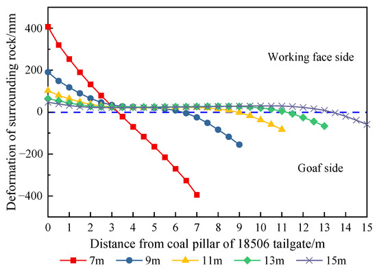
Figure 7.
Internal horizontal displacement of coal pillars with different widths during mining.
The results of numerical simulation show that during mining, the coal pillars with different widths show great differences. When the width of the coal pillars is 7~9 m, the high stress in the coal pillars concentrates, the stability of the coal pillars decreases, and the deformation of surrounding rocks is large. When the width of thee coal pillar in the roadway protection reaches 11 m or more, the internal stress of the coal pillar is basically kept within 20 MPa, the integrity of the coal pillar is high, and the deformation of the surrounding rock is stable. Combined with theoretical calculation results and engineering experience, when the width of the coal pillar is 10~11 m, the bearing stress of the coal pillar is low and the deformation of the coal pillar is stable, which can avoid the run-through of the internal plastic zone of the coal pillar during mining. For 7 m coal pillar, the penetration of the internal plastic zone of the coal pillar during mining can only be prevented by changing the structural characteristics of the overlying strata to reduce stress concentration. Therefore, the technology of roof cutting and pressure relief of the hard overburden in gob-side entry is put forward, which can cut off the propagation path of overlying strata by hydraulic fracturing and ensure the safety of the coal pillar in the roadway protection during mining.
3. Research on Pressure Relief Parameters of Hard Overburden Cutting in Gob-Side Entry with Small Coal Pillars
3.1. Simulation Scheme
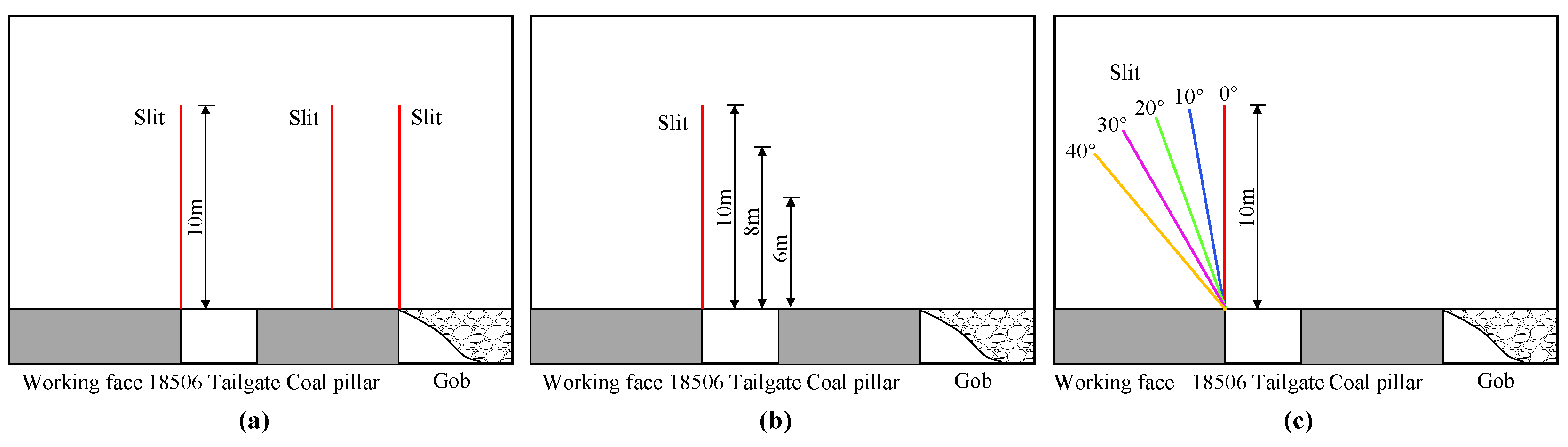
Roof cutting and pressure relief can change the roof structure of the hard overburden, which is an effective measure to reduce the overlying load of the roadway. However, at present, there are different views on the location of roof cutting, mainly focusing on the side of the working face, above the coal pillar and the goaf. Cutting the roof on the side of the working face can change the fracture line of the overlying strata, make the overlying strata collapse vertically after the mining of the working face, and better fill the goaf. Cutting the roof above the coal pillar can reduce the energy accumulation inside the coal pillar. Goaf side roof cutting can effectively cut off the gob side roof, reduce the length of the hanging roof, and reduce the effect on the coal pillar [39,40,41,42,43]. However, for different geological conditions, different roadway layouts, different coal pillar widths, and other issues, specific problems should be analyzed, the best hydraulic fracturing topping position should be determined, and reasonable topping parameters should be selected so that the internal stress environment of the coal pillar can be optimized. In view of this, the characteristics of coal pillar isolation stability under different top cutting positions, heights, and angles are studied, respectively, and the schematic diagram of the simulation scheme is shown in Figure 8.
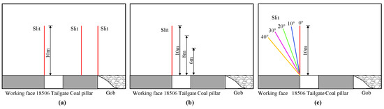
Figure 8.
Schematic diagram of simulation scheme: (a) different cutting positions; (b) different cutting heights; (c) different cutting angles.
3.2. Different Top Cutting Positions
In order to compare the influence of different roof cutting positions on the stress distribution of surrounding rock, this simulation selects three roof cutting positions along the coal seam dip direction, namely, the working face side, above the coal pillar and the goaf side, with a roof cutting angle of 0° and a roof cutting height of 10 m.
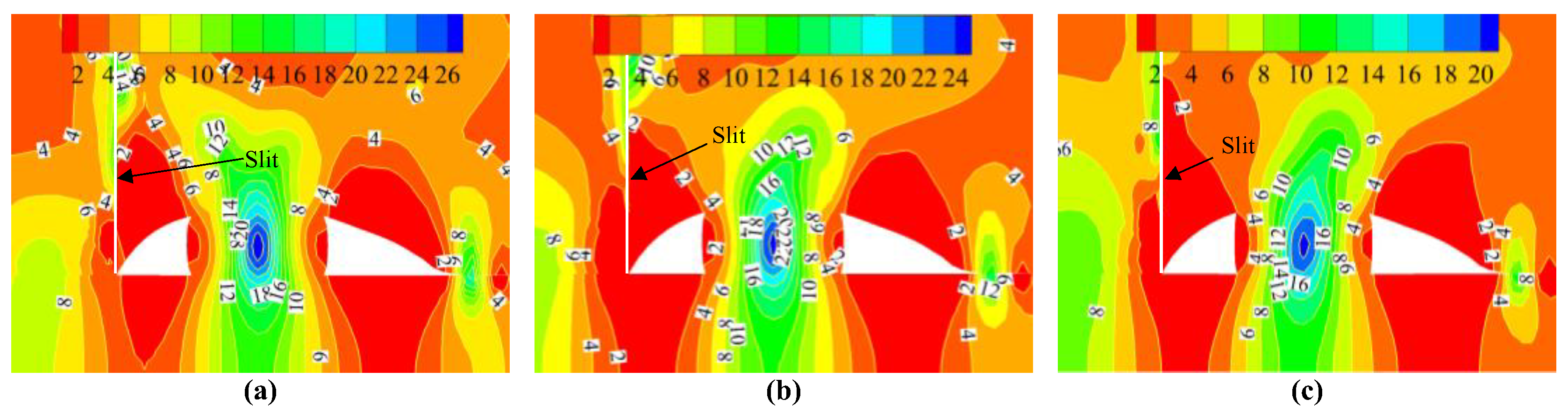
The nephogram of the vertical stress distribution of the surrounding rock at different top cutting positions is shown in Figure 9. It can be seen from Figure 9: ① There is a significant difference in the effect of different slit positions on the coal pillars, with the best effect of roof cutting on the side of the working face, followed by the roof cutting on the side of goaf, and the roof cutting above the coal pillars. ② When the top cutting position is located on the side of the working face, the working face can fall vertically and fill the goaf after mining, and the stress will not be transferred to the coal pillar side, which is the most ideal top cutting effect.
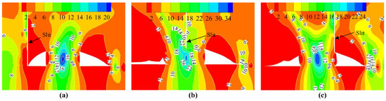
Figure 9.
Nephogram of vertical stress distribution of surrounding rock at different top cutting positions: (a) working face side; (b) above coal pillar; (c) gob side.
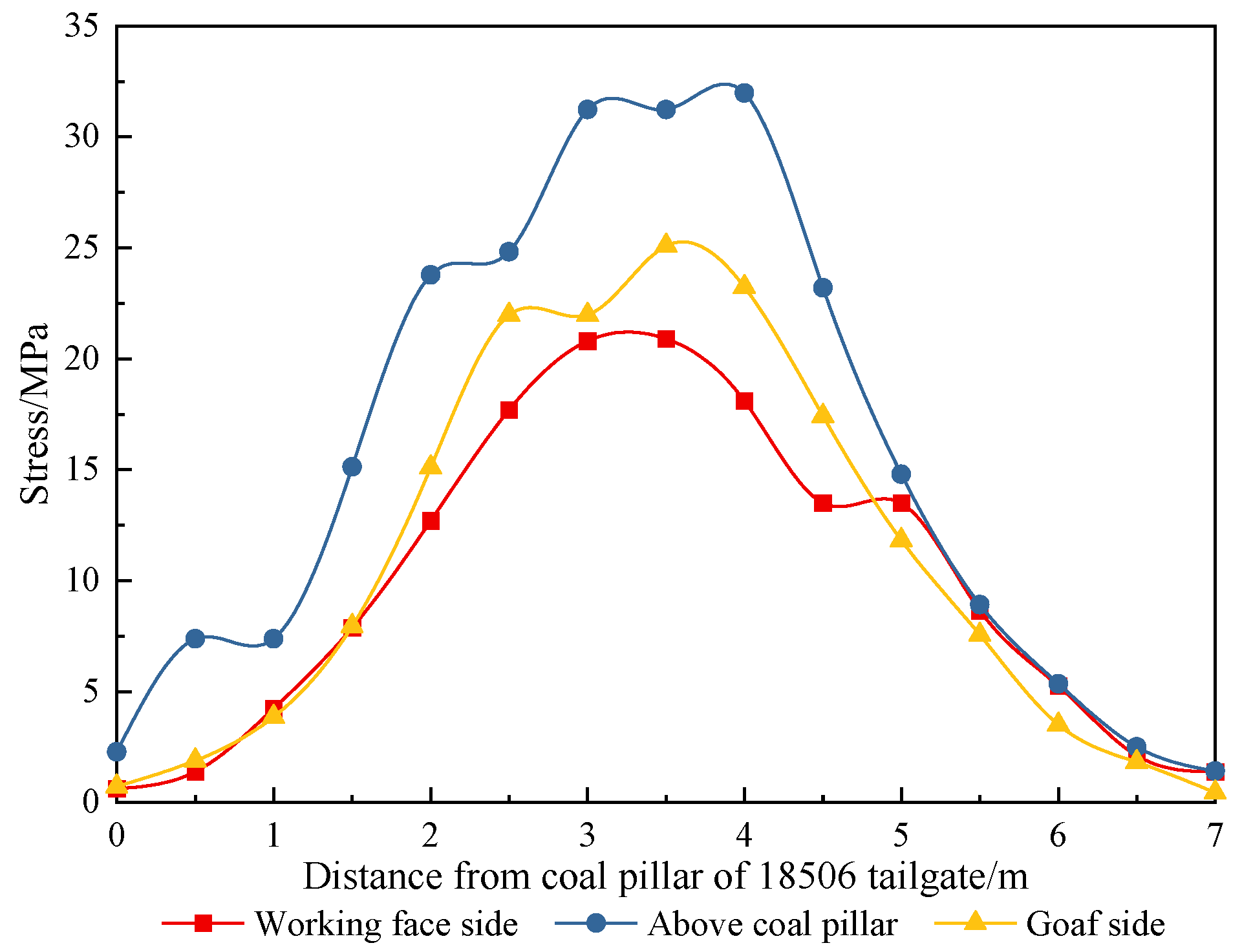
The vertical stress curves of the coal pillars in the roadway protection at different top cutting positions are shown in Figure 10. It can be seen from Figure 10: ① When the roof cutting position is located at the side of the working face, the roof fracture line is located at the edge of the roadway, and the roof can completely collapse after the mining of the working face, thus reducing the pressure on the coal pillar of the roadway protection. The peak stress inside the coal pillar of the roadway protection is only 20.8MPa, which is 32.5% lower than that without roof cutting. ② When the top cutting position is above the coal pillar, the peak stress in the coal pillar reaches 31.9MPa, which destroys the integrity of the coal pillar in the isolated bearing area. ③ When the roof cutting position is located at the goaf side, the peak stress in the coal pillar is 25.1 MPa, which is 18.5% lower than that without roof cutting.
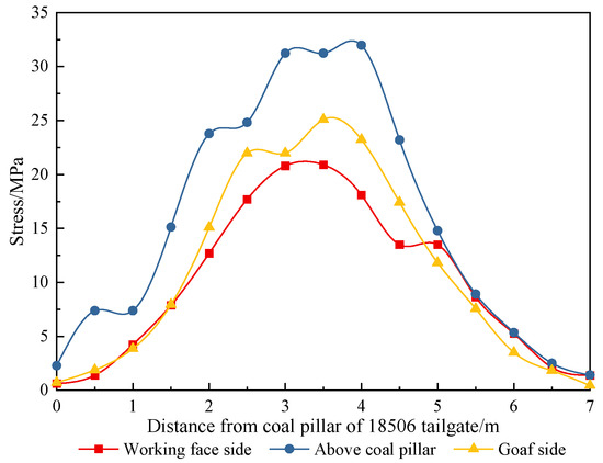
Figure 10.
Vertical stress curve of surrounding rock at different top cutting positions.
3.3. Different Cutting Heights
In order to compare the influence of different cutting heights on the stress distribution of the surrounding rock, three cutting heights are selected in this simulation, which are 6 m, 8 m, and 10 m, respectively, the cutting angle is 0°, and the cutting position is on the working face side.
Figure 11 shows the nephogram of the vertical stress distribution of the surrounding rocks with different top cutting heights. It can be seen from Figure 11: ① With the increase in the top cutting height, the cutting effect on the side stress of the working face becomes more obvious, and the internal stress of the coal pillar lessens. ② The surrounding rocks on both sides of the kerf squeeze each other, resulting in a small degree of stress concentration along the kerf direction.
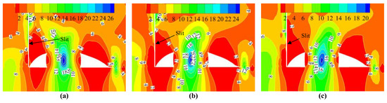
Figure 11.
Nephogram of vertical stress distribution of surrounding rock with different top cutting heights: (a) H = 6 m; (b) H = 8 m; (c) H = 10 m.
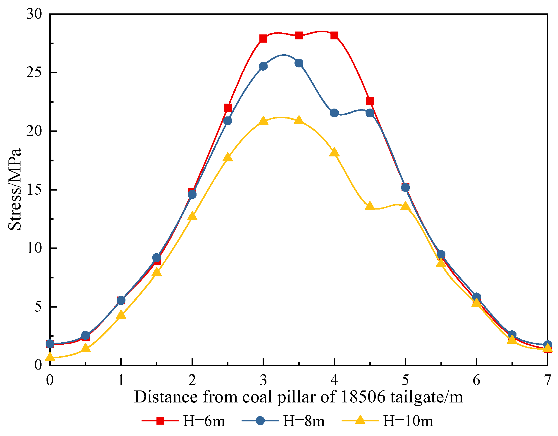
The vertical stress curves of the surrounding rocks with different top cutting heights are shown in Figure 12. It can be seen from Figure 12: ① When the top cutting height is 6 m, the peak stress in the coal pillar is 28.2 MPa, which is only 8.4% lower than that without top cutting. ② When the top cutting height is 8 m, the peak stress in the coal pillar is 25.8 MPa, which is 16.2% lower than that without top cutting. ③ When the height of roof cutting increases to 10 m, the peak stress in the coal pillar is only 20.8 MPa, which is 32.5% lower than that without roof cutting.

Figure 12.
Vertical stress curve of surrounding rock with different top cutting heights.
3.4. Different Top Cutting Angles
In order to compare the influence of different cutting angles on the stress distribution of the surrounding rock, this simulation selects five cutting angles, which are 0°, 10°, 20°, 30°, and 40°. The length of the cutting seam is 10 m, and the cutting position is on the working face side.
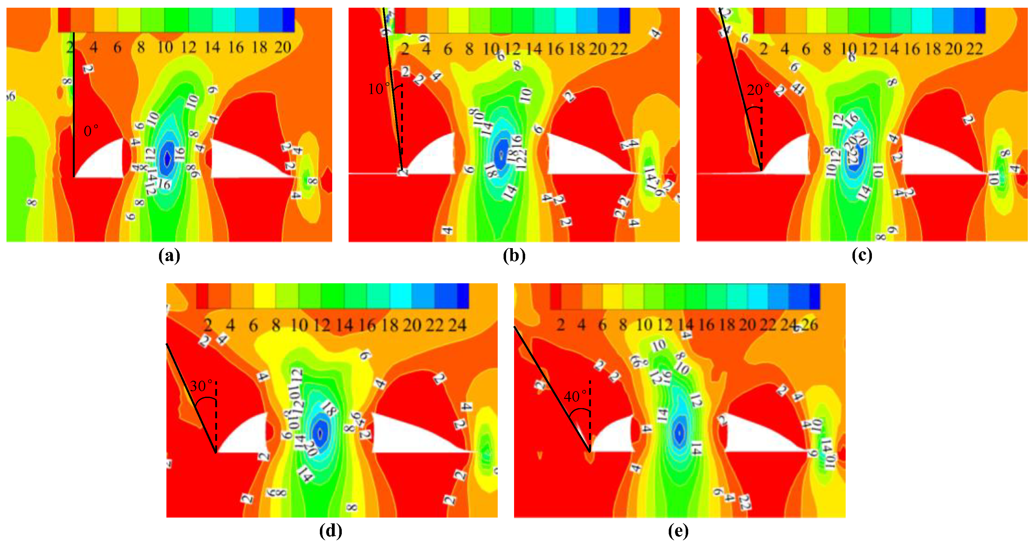
The nephogram of the vertical stress distribution of the surrounding rock with different top cutting angles is shown in Figure 13. It can be seen from Figure 13: ① With the increase in the roof cutting angle, the length of the hanging roof also increases, which leads to the aggravation of the stress concentration in the coal pillar. ② Although the top cutting angles are different, they all change the position of the roof fracture line to some extent, and the top cutting angle of the vertical roadway roof is the best.

Figure 13.
Nephogram of vertical stress distribution of surrounding rock with different top cutting angles: (a) 0°; (b) 10°; (c) 20°; (d) 30°; (e) 40°.
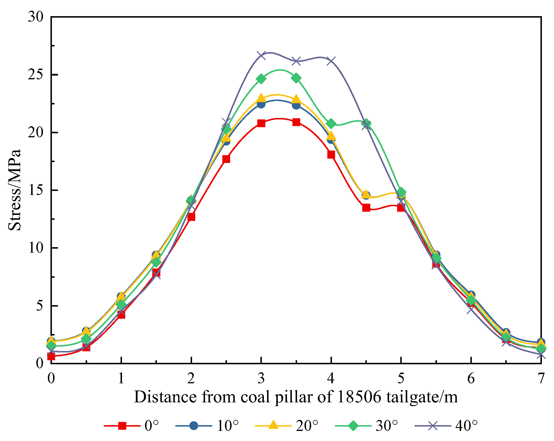
The vertical stress curves of the surrounding rocks with different top cutting angles are shown in Figure 14. It can be seen from Figure 14: ① With the increase in the top cutting angle, the peak stress in the coal pillar is 20.8 MPa, 22.4 MPa, 22.9 MPa, 24.7 MPa, and 26.6 MPa. ② The top cutting angle mainly affects the peak stress change in the middle of the coal pillar, but has little effect on both sides of the coal pillar.
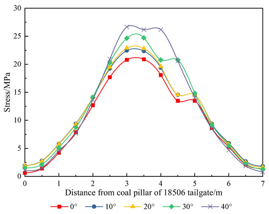
Figure 14.
Vertical stress curve of surrounding rock with different top cutting angles.
According to the above numerical simulation results, it is shown that the internal stress of the coal pillar can be effectively reduced, and the run-through of the internal plastic zone can be avoided. At the same time, the working face side is the best cutting position, and the cutting effect is directly proportional to the cutting height and inversely proportional to the cutting angle.
4. Research on Directional Controllability of Cracking in Hydraulic Fracturing of Hard Overburden
4.1. Simulation Scheme
In Section 3, it is determined that the best cutting position of hydraulic fracturing along the dip direction is the working face side. However, the mechanism of hydraulic fracturing cutting and pressure relief, especially the mechanism of hydraulic fracture propagation, is not yet clear. In the research of the hydraulic fracturing propagation law, many scholars have completed extensive research through experiments and simulations, among which XFEM is a method that can effectively simulate fracture propagation in an intact rock mass [44,45,46]. Therefore, with the help of ABAQUS finite element software, the fracture propagation mechanism of hydraulic fracturing in different stress fields under hard overburden conditions is simulated, providing parameter guidance for engineering tests. The simulated rock stratum is medium sandstone, and a two-dimensional plane model with length × width = 20 m × 20 m is established. The Mohr–Coulomb constitutive model is adopted, and relevant physical and mechanical parameters are shown in Table 2.
Table 2.
Physical and mechanical parameters.
4.2. Mechanism of Hydraulic Fracture Propagation in Different Stress Fields
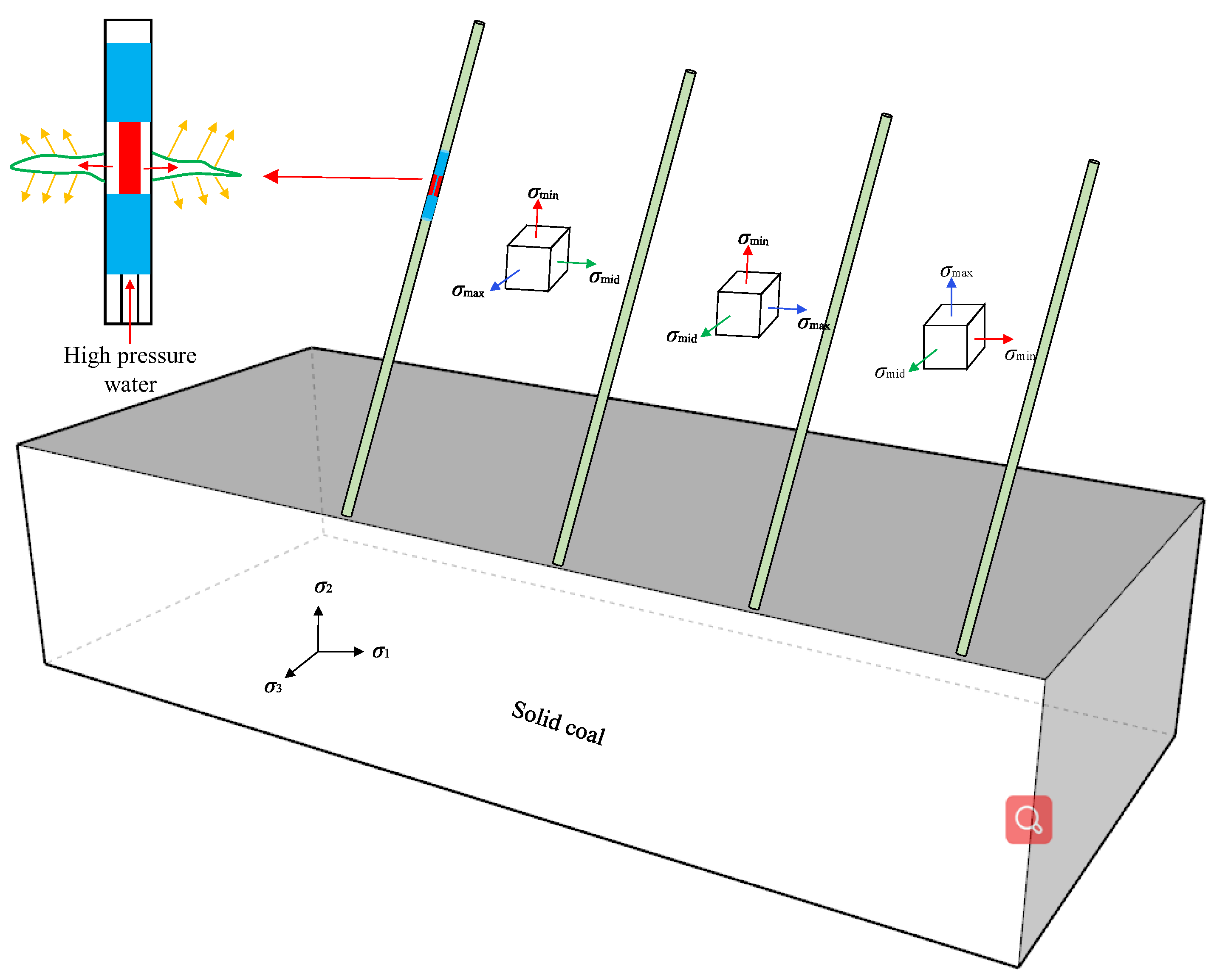
Hydraulic fracturing is a technology that takes high-pressure water as the power, cracks as the carrier, and stress field environment as the leading factor, in which the stress field environment is difficult to control. After the excavation of the roadway, the initial stress state of the rock mass is changed, and the direction and magnitude of the maximum and minimum principal stresses are changed to varying degrees. At the same time, the stress field of the surrounding rock of the roadway is more complicated due to the influence of mining stress and other factors. When the roof stress environment is constantly changing, the hydraulic fracturing of each borehole will also show different effects, so it is necessary to study the hydraulic fracturing mechanism under different stress fields. The stress field distribution of the roof is shown in Figure 15.
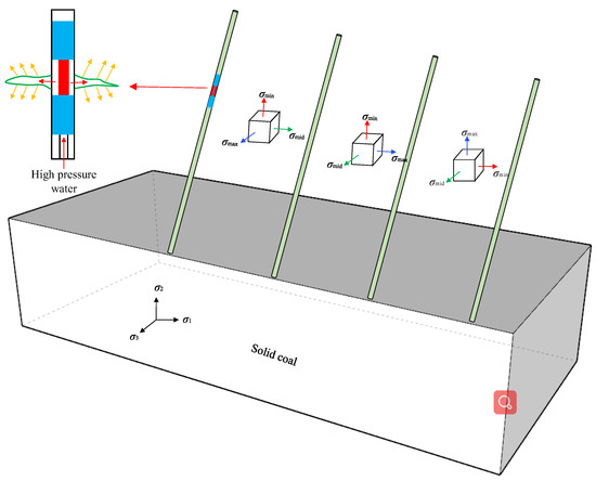
Figure 15.
Distribution of stress field.
The fracture propagation effect of hydraulic fracturing in different stress fields is shown in Figure 16. It can be seen from Figure 16: ① When σ1 is the minimum principal stress and σ2 is the maximum principal stress, the crack expands in the vertical direction; when σ1 is the maximum principal stress and σ2 is the minimum principal stress, the crack extends along the horizontal direction; when the stress values of σ1 and σ2 are equal, the cracks propagate along the original direction. ② During hydraulic fracturing, the stress vector is mainly concentrated at the crack tip. ③ When the injection point is located in the middle of the fracture, the maximum deformation of the rock mass is located in the center of the injection point, which is a semi-ellipsoid and spreads outward.
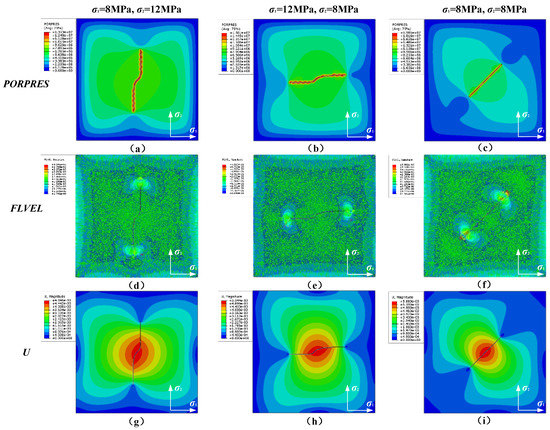
Figure 16.
Fracture propagation effect of hydraulic fracturing in different stress fields. (a) PORPRES, σ1 = 8 MPa, σ2 = 12 MPa; (b) PORPRES, σ1 = 12 MPa, σ2 = 8 MPa; (c) PORPRES, σ1 = 8 MPa, σ2 = 8 MPa; (d) FLVEL, σ1 = 8 MPa, σ2 = 12 MPa; (e) FLVEL, σ1 = 12 MPa, σ2 = 8 MPa; (f) FLVEL, σ1 = 8 MPa, σ2 = 8 MPa; (g) U, σ1 = 8 MPa, σ2 = 12 MPa; (h) U, σ1 = 12 MPa, σ2 = 8 MPa; (i) U, σ1 = 8 MPa, σ2 = 8 MPa.
4.3. Propagation Mechanism of Artificial Precast Cracks in Different Stress Fields
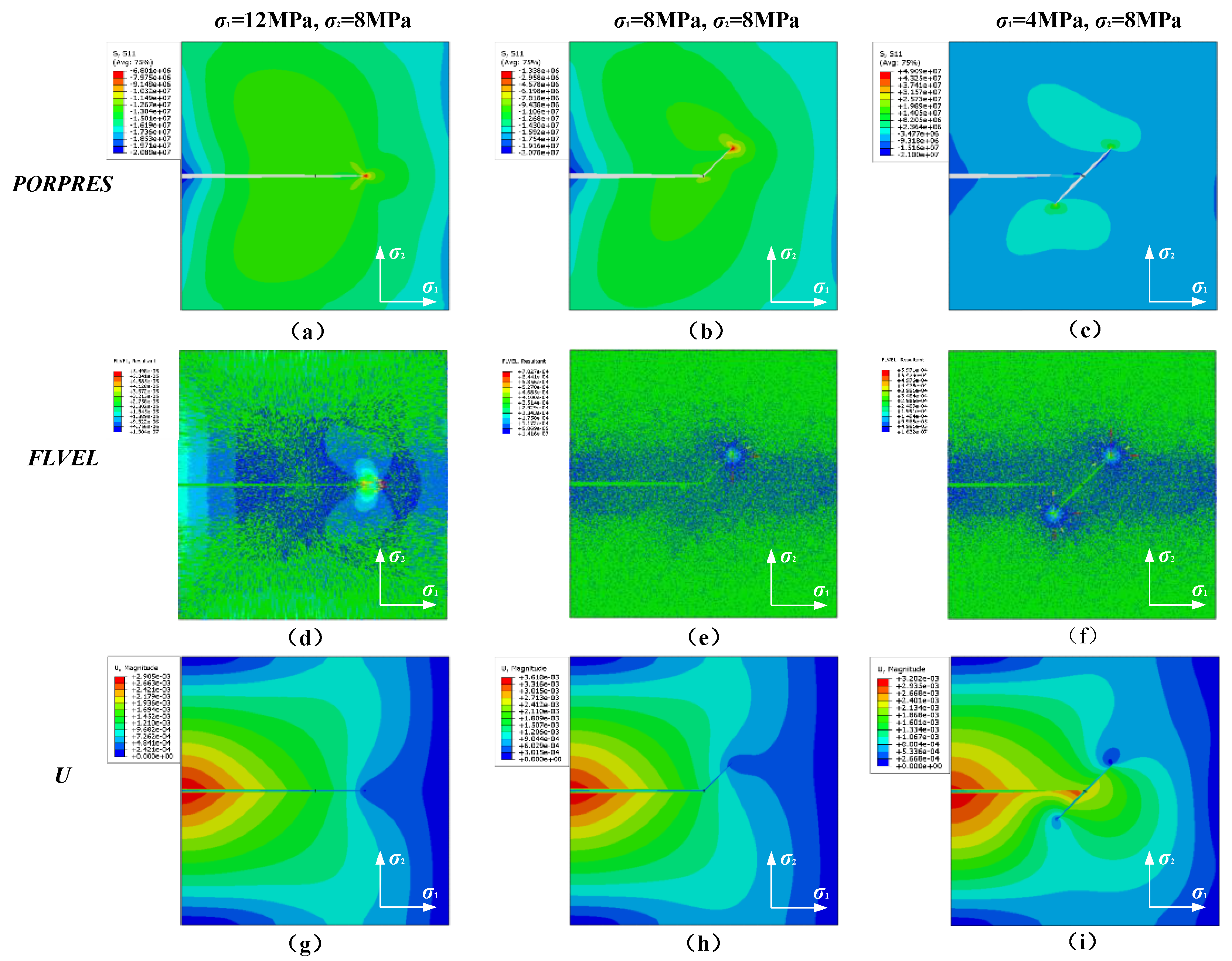
Artificial fractures are prefabricated in the rock strata in advance, fixing σ2 = 8 MPa, and taking σ1 as 4 MPa, 8 MPa, and 12 MPa, to simulate the propagation mechanism of artificial prefabricated fractures in different stress field environments. The simulation results are shown in Figure 17. It can be seen from Figure 17: ① When σ1 > σ2, the direction of the hydraulic fracture does not deflect after crossing the artificial prefabricated fracture, and it continues to expand along the horizontal direction; when σ1 = σ2, the hydraulic fracture intersects with the artificial prefabricated fracture and deflects along the unilateral direction of the artificial prefabricated fracture; when σ1 < σ2, the hydraulic fracture intersects with the artificial prefabricated fracture and deflects along both sides of the artificial prefabricated fracture. ② The stress vector is concentrated along the crack propagation path and points to the crack tip. ③ When the hydraulic fracture does not deflect, or only deflects along one side of the artificial precast fracture, the deformation always decreases from the injection point to the inside of the rock mass along the fracture propagation direction; when the hydraulic fracture deflects along both sides of the artificial precast fracture, large deformation occurs at the injection point and the intersection point of the fracture, which indicates that the fracturing effect is significant.
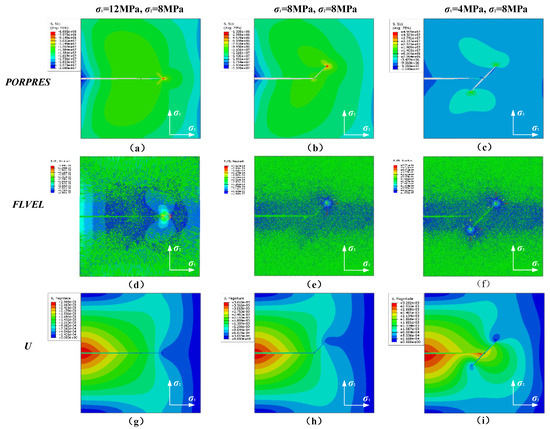
Figure 17.
Expansion of artificial prefabricated cracks in different stress fields. (a) PORPRES, σ1 = 8 MPa, σ2 = 12 MPa; (b) PORPRES, σ1 = 12 MPa, σ2 = 8 MPa; (c) PORPRES, σ1 = 8 MPa, σ2 = 8 MPa; (d) FLVEL, σ1 = 8 MPa, σ2 = 12 MPa; (e) FLVEL, σ1 = 12 MPa, σ2 = 8 MPa; (f) FLVEL, σ1 = 8 MPa, σ2 = 8 MPa; (g) U, σ1 = 8 MPa, σ2 = 12 MPa; (h) U, σ1 = 12 MPa, σ2 = 8 MPa; (i) U, σ1 = 8 MPa, σ2 = 8 MPa.
According to the XFEM simulation results, when the horizontal stress is greater than the vertical stress, the crack tends to expand along the horizontal direction, which is conducive to the formation of horizontal linear through cracks in engineering applications, but the vertical crack expansion effect is poor. When the vertical stress is greater than the horizontal stress, the crack tends to expand along the vertical direction, which is conducive to the formation of a planar fracture zone in engineering applications, and is an ideal top cutting effect.
5. Industrial Test
5.1. Design of Hydraulic Fracturing Topping Scheme
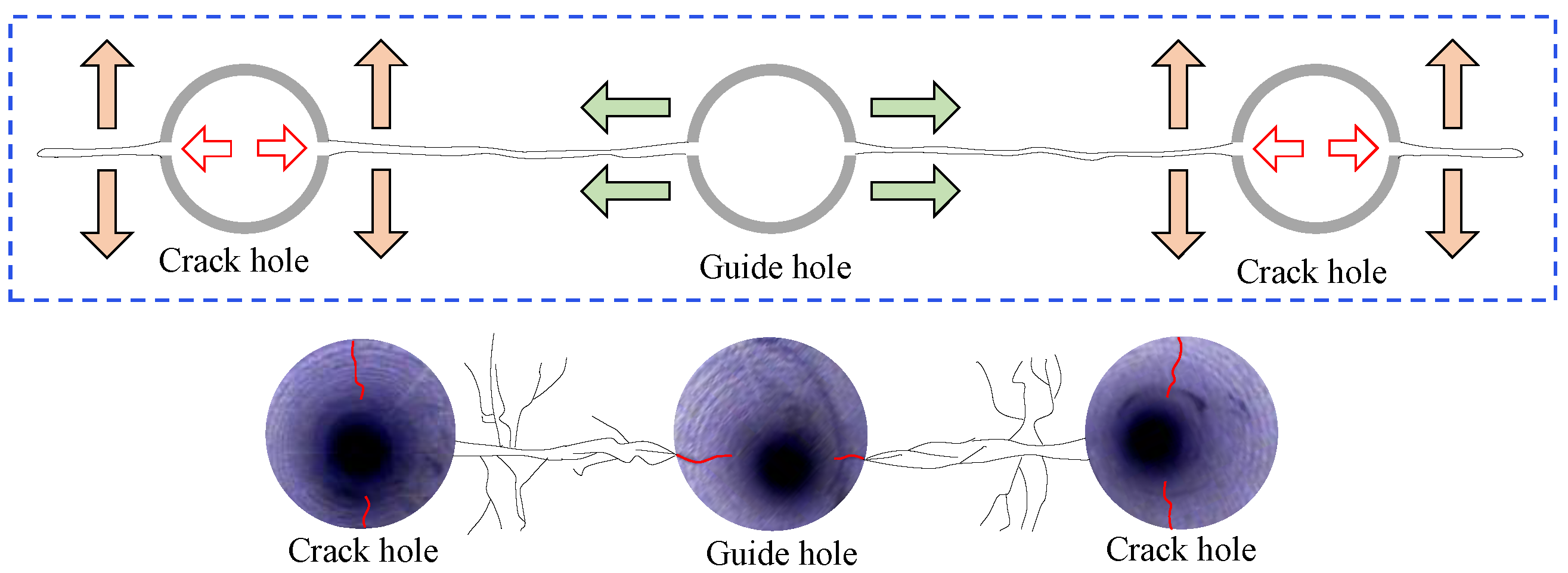
Combined with the results of numerical simulation, this paper puts forward the pressure relief measures of hard overburden rock cutting with the core technology of an “artificial local stress field to realize directional control of hydraulic fracturing.” By setting the “pilot hole” to release the horizontal stress in advance, the local stress field above the roadway roof can be artificially created, and the crack can be guided and controlled by the “crack-causing hole” to form a continuous hydraulic fracture structural plane, cut off the stress transmission path, and improve the roof stress environment.
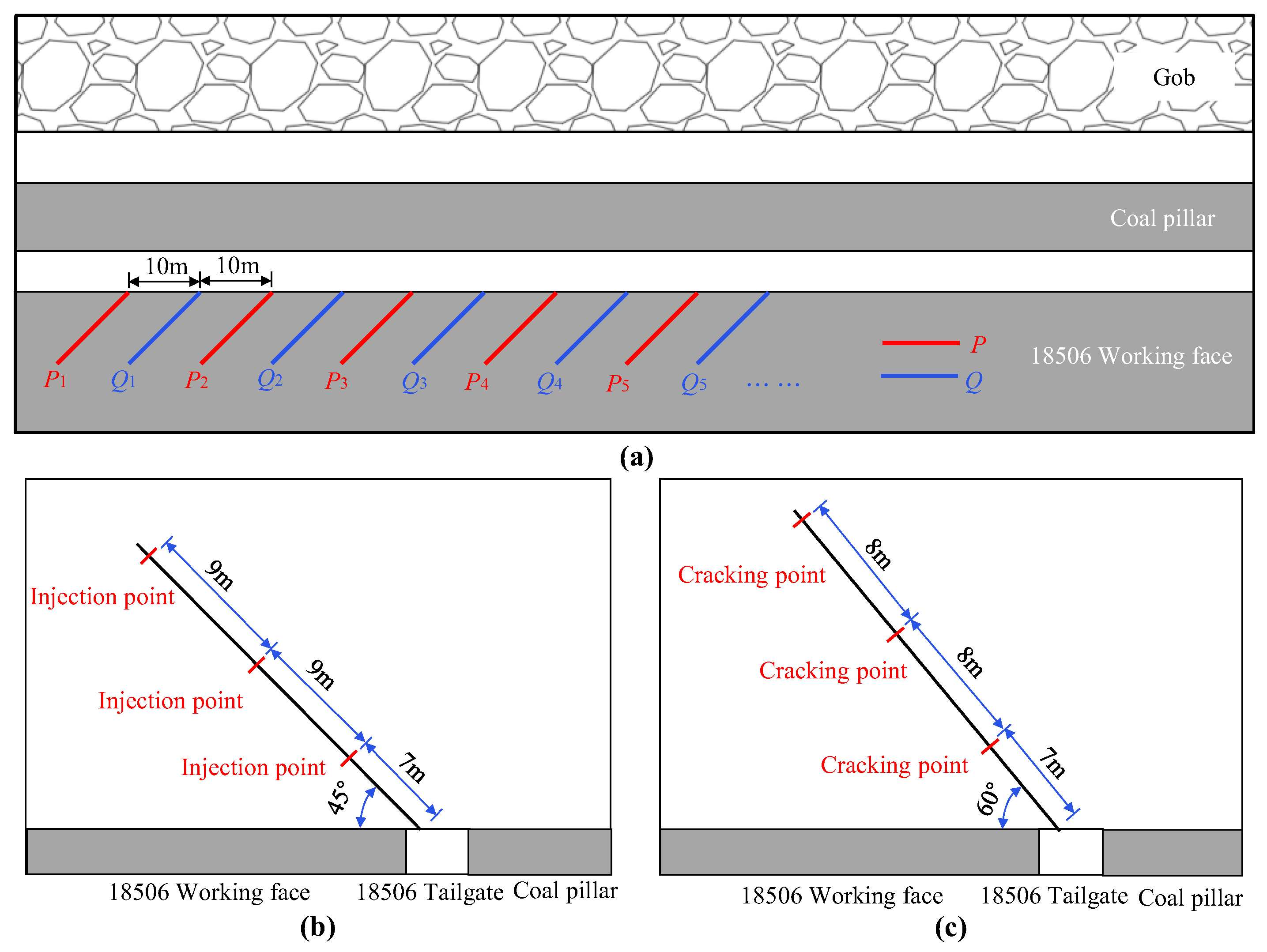
In view of this, the hydraulic fracturing, roof cutting, and pressure relief scheme of the 18506 working face return air roadway is determined. Starting at 15 m away from the open cut, hydraulic fracturing topping construction is carried out. Two types of drilling holes, P and Q, are arranged, with 16 groups of each type of drilling hole, of which the P type drilling hole is the pilot hole and the Q type drilling hole is the fracturing hole. The specific drilling arrangement is shown in Figure 18, and the specific drilling parameters are shown in Table 3. The action mechanism of the pilot hole and the crack-causing hole is shown in Figure 19.
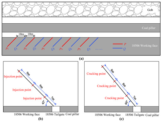
Figure 18.
Layout of hydraulic fracturing boreholes in the 18506 working face: (a) layout of the drillings; (b) type P borehole; (c) type Q borehole.
Table 3.
Specific parameters of hydraulic fracturing drilling.
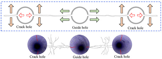
Figure 19.
Schematic diagram of the action of the pilot hole and the crack-causing hole.
The design length of the pilot hole is 26 m, and three injection points are arranged for each hole. The specific operation process is as follows: drill the hole to the designated position, push the water injection steel pipe into the injection point, seal the upper and lower sections of the injection point with a packer, inject high-pressure water into the sealed section, and turn off the pump to release the pressure after the pressure of the high-pressure water is stable. After the release of the high pressure water, re-pressurize it until it is stable, and repeat this for 2~3 times before fracturing the next section. The horizontal stress in this area is released by hydraulic fracturing in the upper and lower sections, and a continuous weak structural plane is formed in the roof strata so that the vertical stress becomes the maximum principal stress, thus controlling the fracture turning of hydraulic fracturing.
The designed length of the fracturing hole is 24 m, and three fracturing points are arranged in each drilling hole. The specific operation flow is as follows: drilling the hole to the designated position, pushing the water injection steel pipe into the fracturing point, sealing the upper and lower sections of the fracturing point with a packer, injecting high-pressure water into the sealing section, and after the first fracturing, turning off the pump to release the pressure in order to carry out the next fracturing task. The fracturing time of each fracturing point is 15 min. The fracturing task of the construction section is completed in turn, and the hydraulic fracture in the fracturing hole first expands along the horizontal direction. Under the action of the pilot hole, the horizontal fracture deflects and expands again along the approximate vertical direction, and finally, a three-dimensional continuous rock fracture is formed between adjacent fracturing sections.
5.2. Mine Pressure Monitoring
5.2.1. Peeping through the Hole
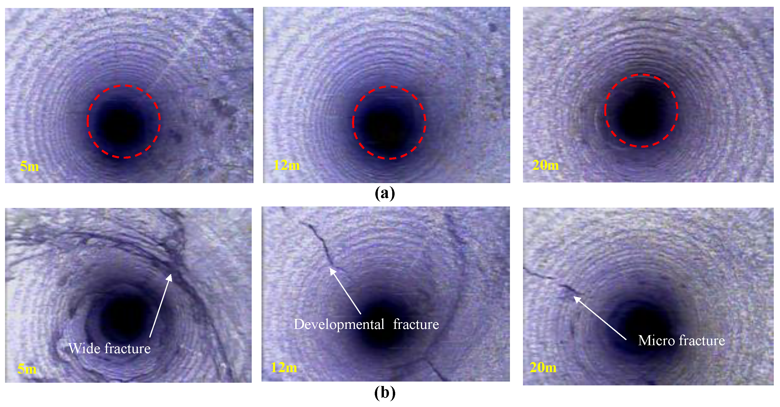
In order to test the effect of hydraulic fracturing, the distribution of cracks in the rock mass before and after fracturing is observed using a borehole peeper, and the observation results are shown in Figure 20. Before cracking, there are a few tiny cracks in the shallow rock mass, no visible cracks in the deep rock mass, and high integrity of the roof strata. After cracking, the cracks in the hole wall developed clearly, the shallow cracks appeared with wide width, the middle and deep cracks developed noticeably, and the number of cracks increased significantly.
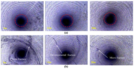
Figure 20.
Drilling peep results before and after hydraulic fracturing: (a) before fracturing; (b) after fracturing.
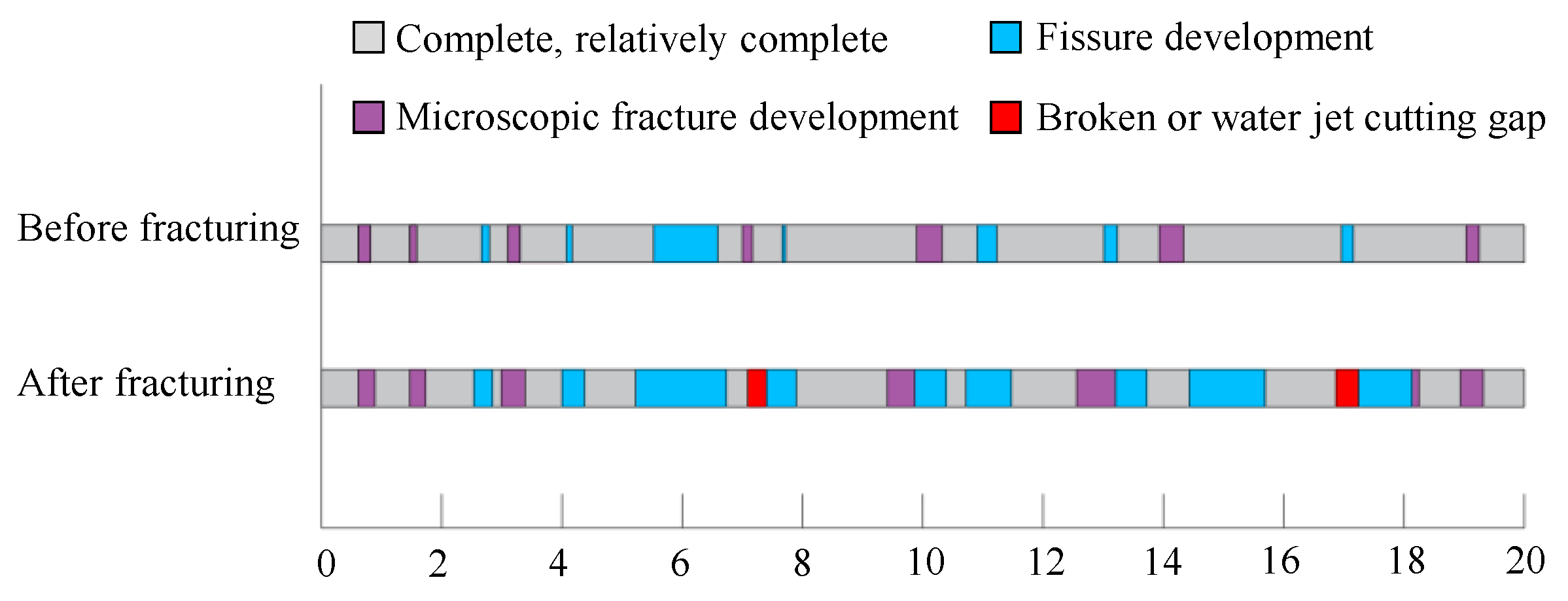
Next, the fracture development of the rock mass before and after hydraulic fracturing are compared, and a sketch map of fracture development in drawn, as shown in Figure 21. Moreover, by examining the sketch map of fracture development, it is found that after hydraulic fracturing, the rock mass in the borehole forms an obvious fracture development zone under the influence of high-pressure water. This shows that hydraulic fracturing can effectively reduce the integrity of the hard roof and improve the stress distribution of the roof.
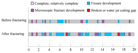
Figure 21.
Sketch of fracture development before and after fracturing.
5.2.2. Surface Displacement
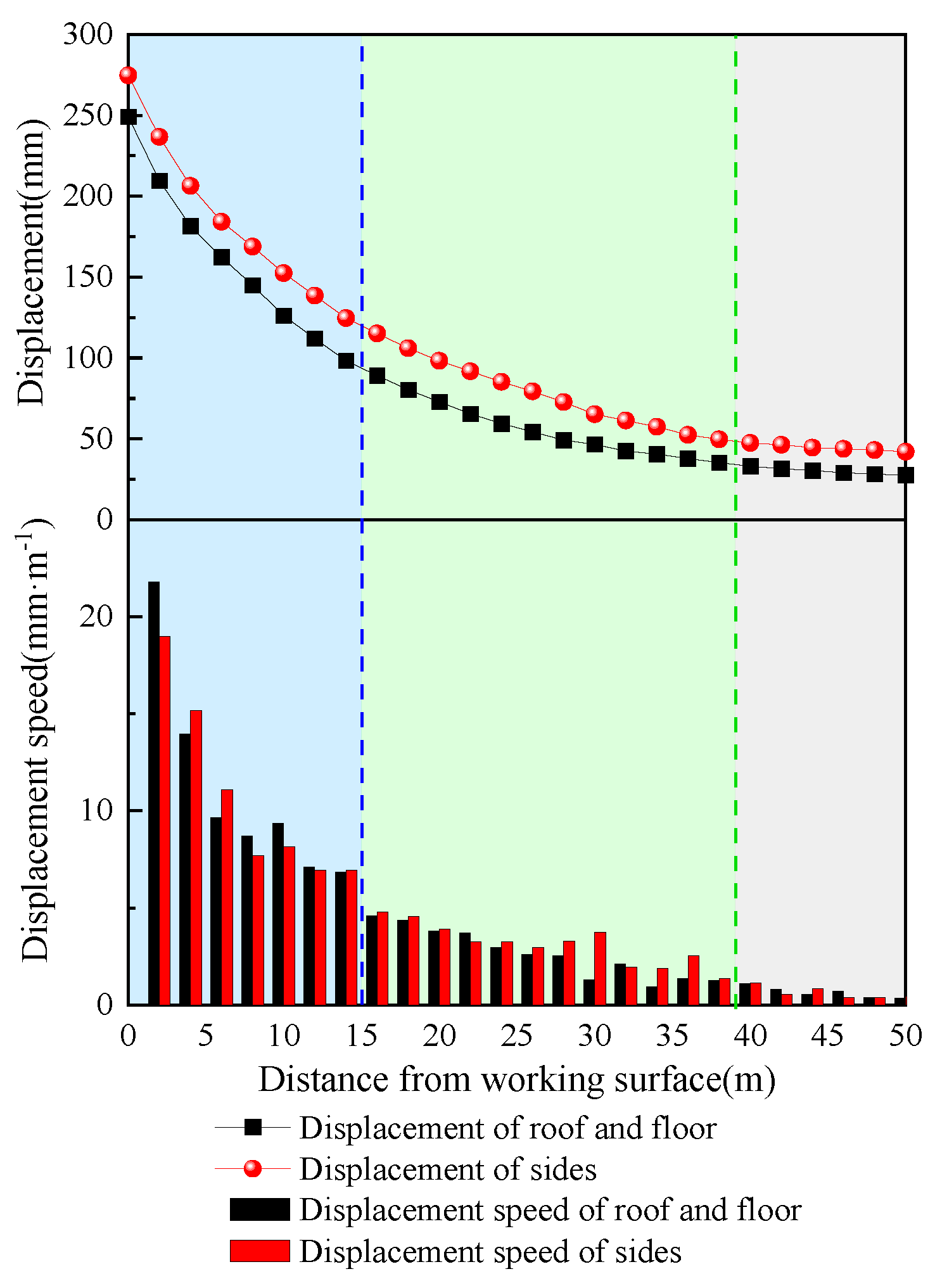
After hydraulic fracturing, the deformation of the roof and floor of the roadway and the surrounding rocks of the two sides behind the working face are monitored, and the displacement changes and displacement change rates of the roof and floor and the two sides are counted. The monitoring results are shown in Figure 22. When the observation point is more than 40 m away from the working face, the surrounding rock is relatively stable. When it is 50 m away from the working face, the deformation of the roof and floor is only 27.5 mm, and that of the two sides is only 42.1 mm. Within the range of 15~40 m from the working face, the movement trend of surrounding rock begins to strengthen, and the deformation rate of roof and floor and two sides is basically stable at about 5 mm/m. Within 15 m away from the working face, the surrounding rock moves violently, and when the roadway is flush with the working face, the deformation of the surrounding rock is the largest, with the roof and floor reaching 249.1 mm and the deformation of the two sides reaching 274.7 mm This indicates that after hydraulic fracturing, the stress distribution of the surrounding roof rock is improved, the deformation of the surrounding rock is controlled, the internal stress of the coal pillar is released, and the coal pillar will not be significantly destroyed, which can ensure the safety of the mining face.
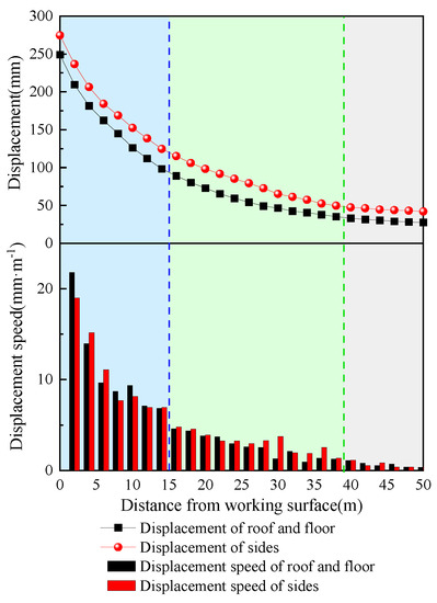
Figure 22.
Roadway surface displacement curve.
6. Conclusions
This paper makes up for the defects of the uncontrollable direction of fracture propagation in hydraulic fracturing technology and provides the following conclusions:
- (1)
- The hard roof of the 18506 working face is difficult to collapse, and the hanging roof length is long during mining, which leads to high bearing stress of the coal pillars in the roadway protection, the run-through of the internal plastic zone, and a poor isolation effect, easily leading to harmful gas leakage in the goaf, seriously threatening safe mine production. It is necessary to cut the roof and relieve pressure to ensure that the internal plastic zone of the coal pillar is not penetrated during mining.
- (2)
- Roof cutting and pressure relief can actively cut off the upper roof, change the structure of the hard overburden and broken roof, cut off the stress transmission path, and improve the surrounding rock stress environment of the roof. The top cutting position, top cutting height, and top cutting angle are the key points to realize top cutting pressure relief. The best top cutting position is on the side of the working face, the most reasonable top cutting angle is 0°, and the top cutting height is directly proportional to the top cutting effect.
- (3)
- The propagation mechanism of hydraulic fracture and artificial prefabricated fracture under different stress fields is analyzed. Hydraulic fracture expands perpendicular to the direction of minimum principal stress during high-pressure water injection, and after the artificial prefabricated fracture intersects with the hydraulic fracture, there are three resulting forms of fracture: penetration, unilateral deflection, and bilateral deflection.
- (4)
- The technology of hard overburden roof cutting and pressure relief with an “artificial local stress field realizing directional control of hydraulic fracturing” at its core is proposed, and the industrial test is carried out, reducing the length of the hard overburden roof, releasing the internal stress of the coal pillar in the roadway protection, controlling the deformation, and ensuring the safety of the mining face.
Author Contributions
Conceptualization, X.W. (Xiangyu Wang); methodology, F.Z.; software, M.L.; validation, X.Z.; formal analysis, G.L.; investigation, G.W.; resources, X.W. (Xiangdong Wang); data curation, J.Z.; writing—original draft preparation, D.C.; writing—review and editing, X.W. (Xiangyu Wang); visualization, Y.Y.; supervision, D.C.; project administration, Y.Y.; funding acquisition, X.W. (Xiangyu Wang). All authors have read and agreed to the published version of the manuscript.
Funding
This research was funded by the National Natural Science Foundation of China (grant numbers 52174132 and 51904269), the Postgraduate Research and Practice Innovation Program of Jiangsu Province (grant number KYCX22_2625), and the Graduate Innovation Program of China University of Mining and Technology (grant number 2022WLJCRCZL012).
Informed Consent Statement
Written informed consent has been obtained from the patient(s) to publish this paper.
Acknowledgments
This research was supported by the National Natural Science Foundation of China (52174132), which is gratefully acknowledged.
Conflicts of Interest
The authors declare no conflict of interest.
References
- Jia, J.; Cao, L.W.; Zhang, D.J.; Chai, X.W.; Liu, S.Q.; Ma, L.; Han, L. Study on the fracture characteristics of thick-hard limestone roof and its controlling technique. Study Fract. Charact. Thick-Hard Limest. Roof Its Control. Tech. 2017, 76, 605. [Google Scholar] [CrossRef]
- Wang, Q.; Fan, Y.P.; Li, G.; Guo, W.X.; Yan, D.H.; Zhang, L.P. Determination of coal pillar width between roadways of fully mechanised caving face with double roadways layout in a thick coal seam. Rock Soil Mech. 2017, 38, 3009–3016. [Google Scholar]
- He, W.R.; He, F.L.; Zhao, Y.Q. Field and simulation study of the rational coal pillar width in extra-thick coal seams. Energy Sci. Eng. 2020, 8, 627–646. [Google Scholar] [CrossRef]
- Hu, M.L.; Zhao, W.L.; Lu, Z.; Ren, J.X.; Miao, Y.P. Research on the reasonable width of the waterproof coal pillar during the mining of a shallow coal seam located close to a reservoir. Adv. Civ. Eng. 2019, 2019, 3532784. [Google Scholar] [CrossRef]
- Sheorey, P.R.; Das, M.N.; Barat, D.; Prasad, R.K.; Singh, B. Coal pillar strength estimation from failed and stable cases. Int. J. Rock Mech. Min. Sci. Geomech. Abstr. 1987, 24, 347–355. [Google Scholar] [CrossRef]
- Zhang, C.W.; Jin, Z.X.; Song, X.M.; Feng, G.R.; Li, Z.; Gao, R.; Zhu, D.F. Failure mechanism and fracture aperture characteristics of hard thick main roof based on voussoir beam structure in longwall coal mining. Energy Sci. Eng. 2020, 8, 340–352. [Google Scholar] [CrossRef]
- Jiang, L.S.; Wu, Q.S.; Wu, Q.L.; Wang, P.; Xue, Y.C.; Kong, P.; Gong, B. Fracture failure analysis of hard and thick key layer and its dynamic response characteristics. Eng. Fail. Anal. 2019, 98, 118–130. [Google Scholar] [CrossRef]
- Xu, C.; Fu, Q.; Cai, X.Y.; Wang, K.; Zhao, Y.X.; Cai, Y.B. Apparent-depth effects of the dynamic failure of thick hard rock strata on the underlying coal mass during underground mining. Rock Mech. Rock Eng. 2019, 52, 1565–1576. [Google Scholar] [CrossRef]
- Lu, Y.Y.; Gong, T.; Xia, B.W.; Yu, B.; Huang, F. Target stratum determination of surface hydraulic fracturing for far-field hard roof control in underground extra-thick coal extraction: A case study. Rock Mech. Rock Eng. 2019, 52, 2725–2740. [Google Scholar] [CrossRef]
- Yu, Y.; Wang, X.Y.; Bai, J.B.; Zhang, L.Y.; Xia, H.C. Deformation Mechanism and Stability Control of Roadway Surrounding Rock with Compound Roof: Research and Applications. Energies 2020, 13, 1350. [Google Scholar] [CrossRef] [Green Version]
- Wang, T.; You, S.; Pei, F.; Bai, X.P. Instability mechanism and control technology of coal pillar bumps under hard roof. J. Min. Saf. Eng. 2017, 34, 54–59. [Google Scholar]
- Zha, W.H.; Li, X.; Hua, X.Z.; Wu, T.F.; Yin, S.Y. Impact and application on narrow coal pillar for roadway protecting from fracture position of upper roof. J. China Coal Soc. 2014, 39, 332–338. [Google Scholar]
- Du, T.T.; Ju, W.J.; Chen, J.Q.; Zhang, C.J.; Li, H.P.; Sun, R.D. Mechanism of rock burst in fully mechanized caving faces under residual coal seams with hard roof. J. Min. Saf. Eng. 2021, 38, 1144–1151. [Google Scholar]
- Yang, H.Y.; Li, Y.; Liu, Y.B.; Cao, S.G.; Pan, R.K.; Wang, H.; Wang, B.; Chen, X.; Zhao, X.L. Structure evolution and stability control mechanism of hard-roof cutting for roadway retaining. J. Min. Saf. Eng. 2021, 38, 766–773. [Google Scholar]
- Yu, B.; Xia, B.W.; Yu, P. Effect of hard roof breaking on gas emission in fully-mechanized sublevel caving mining of extremely thick coal seam. J. China Coal Soc. 2018, 43, 2243–2249. [Google Scholar]
- Yu, B.; Liu, C.Y.; Yang, J.X.; Liu, J.R. Research on the fracture instability and its control technique of hard and thick roof. J. China Univ. Min. Technol. 2014, 42, 342–348. [Google Scholar]
- Li, L.; Bai, J.B.; Wang, X.Y. Rational position and control technique of roadway driving along next goaf in fully mechanized top coal caving face. J. China Coal Soc. 2012, 37, 1564–1569. [Google Scholar]
- He, M.C.; Ma, X.G.; Wang, J.; Zhang, J.B.; Liu, Y.X. Feature analysis of working face strata pressure with roof cutting pressure releasing in medium-thick seam and compound roof condition. Chin. J. Rock Mech. Eng. 2018, 37, 2425–2434. [Google Scholar]
- He, M.C.; Wang, Y.J.; Yang, J.; Gao, Y.B.; Gao, Q.; Wang, S.B. Zonal characteristics and its influence factors of working face pressure using roof cutting and pressure-relief mining method with no pillar and roadway formed automaticly. J. China Univ. Min. Technol. 2018, 47, 1157–1165. [Google Scholar]
- Guo, J.G.; Li, Y.H.; Shi, S.H.; Jiang, Z.S.; Chen, D.D.; He, F.L.; Xie, S.R. Self-forming roadway of roof cutting and surrounding rock control technology under thick and hard basic roof. J. China Coal Soc. 2021, 46, 2853–2864. [Google Scholar]
- Su, C.; Gong, P.L.; Kang, H.P.; Li, C.; Yi, K.; Liu, C.; Li, P. Mechanism of roof cutting and pressure relief in gob-side and high-stress roadway in deep coal mine. J. Min. Saf. Eng. 2020, 37, 1104–1113. [Google Scholar]
- Wang, F.T.; Tu, S.H.; Yuan, Y.; Feng, Y.F.; Chen, F.; Tu, H.S. Deep-hole pre-split blasting mechanism and its application for controlled roof caving in shallow depth seams. Int. J. Rock Mech. Min. Sci. 2013, 64, 112–121. [Google Scholar] [CrossRef]
- Zhang, B.S.; Wang, P.F.; Cui, S.Q.; Fan, M.Z.; Qiu, Y.M. Mechanism and surrounding rock control of roadway driving along gob in shallow-buried, large mining height and small coal pillars by roof cutting. J. China Coal Soc. 2021, 46, 2254–2267. [Google Scholar]
- Hou, C.J.; Wang, X.Y.; Bai, J.B.; Meng, N.K.; Wu, W.D. Basic theory and technology study of stability control for surrounding rock in deep roadway. J. China Univ. Min. Technol. 2021, 50, 1–12. [Google Scholar]
- He, M.C.; Guo, P.F.; Zhang, X.H.; Wang, J. Directional pre-splitting of roadway roof based on the theory of bilateral cumulative tensile explosion. Explos. Shock Waves 2018, 38, 798–803. [Google Scholar]
- Qin, X.Y.; Zhang, Y.H.; Huang, Z.A.; Gao, Y.K. Breaking mechanism and control technology of hard roof in deep and thin coal seam protective layer. J. Cent. South Univ. Sci. Technol. 2021, 52, 4010–4020. [Google Scholar]
- Gao, Y.B.; Yang, J.; Zhang, X.Y.; Xue, H.J.; He, M.C. Study on surrounding rock control of roadways in deep coal mines based on roof cutting and pressure release technology by directional tensile blasting. Chin. J. Rock Mech. Eng. 2019, 38, 2045–2056. [Google Scholar]
- Zhang, S.L.; Zhang, C.S.; Wang, Y.T.; Wang, C.L. Directional Fracture Blasting in Open-off Cut of Fully-Mechanized Caving Mining Face During Primary Mining. Trans. Beijing Inst. Technol. 2017, 37, 135–140. [Google Scholar]
- Zhao, S.K. A comparative analysis of deep hole roof pre-blasting and directional hydraulic fracture for rockburst control. J. Min. Saf. Eng. 2021, 38, 706–719. [Google Scholar]
- Zhang, F.T.; Wang, X.Y.; Bai, J.B.; Wu, W.D.; Wu, B.W.; Wang, G.H. Fixed-length roof cutting with vertical hydraulic fracture based on the stress shadow effect: A case study. Int. J. Min. Sci. Technol. 2022, 32, 295–308. [Google Scholar] [CrossRef]
- Zhou, X.C.; Ma, X.J.; Liao, X.Y.; Qi, S.W.; Li, H.Y. Numerical simulation of abrasive water jet impacting porous rock based on SPH method. Chin. J. Geotech. Eng. 2022, 44, 731–739. [Google Scholar]
- He, Q.Y.; Zhu, L.; Li, Y.C.; Zhang, B.Y. Simulating Hydraulic Fracture Re-orientation in Heterogeneous Rocks with an Improved Discrete Element Method. Rock Mech. Rock Eng. 2021, 54, 2859–2879. [Google Scholar] [CrossRef]
- Guo, J.C.; Zhao, X.; Zhu, H.Y.; Zhang, X.D.; Pan, R. Numerical simulation of interaction of hydraulic fracture and natural fracture based on the cohesive zone finite element method. J. Nat. Gas Sci. Eng. 2015, 25, 180–188. [Google Scholar] [CrossRef]
- Liu, J.W.; Liu, C.Y.; Li, X.H. Determination of fracture location of double-sided directional fracturing pressure relief for hard roof of large upper goaf-side coal pillars. Energy Explor. Exploit. 2020, 38, 111–136. [Google Scholar] [CrossRef] [Green Version]
- Li, X.W.; Chai, Y.J. Determination of pillar width to improve mining safety in a deep burstprone coal mine. Saf. Sci. 2019, 113, 224–256. [Google Scholar] [CrossRef]
- Zhang, J. Stability of Split-Level Gob-Side Entry in Ultra-Thick Coal Seams: A Case Study at Xiegou Mine. Energies 2019, 12, 628. [Google Scholar] [CrossRef] [Green Version]
- Zhang, Z.Z.; Bai, J.B.; Chen, Y.; Yan, S. An innovative approach for gob-side entry retaining in highly gassy fully-mechanized longwall top-coal caving. Int. J. Rock Mech. Min. Sci. 2015, 80, 1–11. [Google Scholar] [CrossRef]
- Zhang, F.T.; Wang, X.Y.; Bai, J.B.; Wang, G.Y.; Wu, B.W. Post-peak mechanical characteristics of the high-water material for backfilling the gob-side entry retaining: From experiment to field application. Arab. J. Geosci. 2020, 13, 386. [Google Scholar] [CrossRef]
- Huang, B.X.; Zhao, X.L.; Chen, S.L.; Liu, J.W. Theory and technology of controlling hard roof with hydraulic fracturing in underground mining. Chin. J. Rock Mech. Eng. 2017, 36, 2954–2970. [Google Scholar]
- Liu, J.W.; Liu, C.Y.; Yao, Q.L.; Si, G.Y. The position of hydraulic fracturing to initiate vertical fractures in hard hanging roof for stress relief. Int. J. Rock Mech. Min. Sci. 2020, 132, 104328. [Google Scholar] [CrossRef]
- Li, B.B.; Li, J.H.; Yang, K.; Ren, C.H.; Xu, J.; Gao, Z. Evolution law of coal permeability based on comprehensive effect of pore pressure and water. J. China Univ. Min. Technol. 2020, 49, 44–53. [Google Scholar]
- Kang, H.P.; Jiang, P.F.; Huang, B.X.; Guan, X.M.; Wang, Z.G.; Wu, Y.Z.; Gao, F.Q.; Yang, J.W.; Cheng, L.X.; Zheng, Y.F.; et al. Roadway strata control technology by means of bolting-modification-destressing in synergy in 1000 m deep coal mines. J. China Coal Soc. 2020, 45, 845–864. [Google Scholar]
- Chen, S.Y.; Zhao, F.; Wang, H.J.; Yuan, G.X.; Guo, Z.B.; Yang, J. Determination of key parameters of gob-side entry retaining by cutting roof and its application to a deep mine. Rock Soil Mech. 2019, 40, 332–342. [Google Scholar]
- Marek, J.; Andrzej, H.; Mateusz, Ć. Directional Hydraulic Fracturing (DHF) of the Roof, as an Element of Rock Burst Prevention in the Light of Underground Observations and Numerical Modelling. Energies 2021, 14, 562. [Google Scholar]
- Karatela, E.; Taheri, A. Three-dimensional hydro-mechanical model of borehole in fractured rock mass using discrete element method. J. Nat. Gas Sci. Eng. 2018, 53, 263–275. [Google Scholar] [CrossRef]
- Wang, S.; Li, D.Y.; Mitri, H.; Li, H. Numerical simulation of hydraulic fracture deflection influenced by slotted directional boreholes using XFEM with a modified rock fracture energy model. J. Pet. Sci. Eng. 2020, 193, 107375. [Google Scholar] [CrossRef]


Publisher’s Note: MDPI stays neutral with regard to jurisdictional claims in published maps and institutional affiliations. |
© 2022 by the authors. Licensee MDPI, Basel, Switzerland. This article is an open access article distributed under the terms and conditions of the Creative Commons Attribution (CC BY) license (https://creativecommons.org/licenses/by/4.0/).