Article

Analysis of the Dynamic Characteristics of the Pump Valve System of an Ultra-High Pressure Liquid Hydrogen Reciprocating Pump

1
Beijing Institute of Aerospace Testing Technology, China Aerospace Science and Technology Corporation, Beijing 100071, China
2
Key Laboratory of Spacecraft Design Optimization and Dynamic Simulation Technologies, Beihang University, Ministry of Education, Beijing 100191, China
*
Author to whom correspondence should be addressed.
Energies 2022, 15(12), 4255; https://doi.org/10.3390/en15124255
Submission received: 6 May 2022 / Revised: 30 May 2022 / Accepted: 5 June 2022 / Published: 9 June 2022
(This article belongs to the Special Issue Liquid Hydrogen Management and Application)

Abstract

:
This paper developed a 3D physical model of the hydraulic end of a high-pressure liquid hydrogen reciprocating pump to research the dynamic characteristics of the pump valve system. Based on dynamic mesh technology, we analyzed the coupling characteristics of pump valve and plunger motion and spool force considering the leakage model, closure model of valve gap, and compressibility of liquid hydrogen. Further, we analyzed the effect of the spring stiffness and preload force on the laws of motion of the pump valve. Finally, a liquid hydrogen pressurization test was conducted to revise the simulation model and verify the accuracy of the simulation. The results of the simulation and test show that the simulation method in this paper can simulate the liquid hydrogen pressurization process more accurately and obtain the motion law of the suction and discharge valves. Both the suction and discharge valves have an opening hysteresis angle of about 40°, and there is a strong coupling relationship between the spool motion and the piston motion and forces. The greater the preload force of the suction valve, the more obvious the oscillation effect of the suction valve. As the preload of the discharge valve increases, the opening hysteresis angle of the discharge valve increases significantly and the closing hysteresis angle decreases. The results of the research can provide some useful reference for the design of pump valves of high-pressure liquid hydrogen reciprocating pumps.

1. Introduction

With the increasing demand for energy, the consumption of fossil fuels and total carbon dioxide emissions are rising rapidly, and the energy change of “clean, low-carbon, safe and efficient” has been the general trend [1]. Currently, there are two important issues restricting the development of hydrogen energy: hydrogen production and hydrogen storage and transportation [2]. Since the volumetric specific energy of liquid hydrogen is three times higher than that of 35 MPa hydrogen and 1.8 times higher than that of 70 MPa hydrogen, liquid storage and transportation have the advantages of low cost, high transportation capacity, high purity, high efficiency, high safety, and small footprint compared with other storage and transportation methods of hydrogen [3]. Among the more than 600 hydrogen refueling stations in operation worldwide, about one-third of them are liquid hydrogen storage stations, mainly in the United States, Europe, and Japan [4,5,6]. The liquid hydrogen pump pressurized vaporization mode is one of the working modes of liquid hydrogen storage and hydrogen refueling station. Its working principle is: liquid hydrogen is stored at low pressure in the station, converted into high-pressure supercritical hydrogen by a liquid hydrogen pump, and then converted into high-pressure hydrogen by a high-pressure liquid hydrogen vaporizer and stored in the hydrogen storage cylinder set. When there is a vehicle to refill with hydrogen, the gas is taken from the hydrogen storage cylinder set and refilled [7]. The liquid hydrogen pump booster vaporization mode also makes full use of the low-temperature cooling energy of liquid hydrogen for pre-cooling the hydrogen before refueling. At the same time, the energy consumption of the liquid hydrogen pump is much lower than that of the compressor, which is used to compress gaseous hydrogen after vaporization [8]. As the core equipment of liquid hydrogen storage and hydrogen refueling station, the pressurization performance of the high-pressure liquid hydrogen pump directly affects the efficiency of liquid hydrogen storage and transportation; therefore it is of great importance [9,10]. The pump valve system is one of the important factors affecting the volumetric efficiency of high-pressure liquid hydrogen booster pumps, and thus it is necessary to carry out a study on the dynamic characteristics of the pump valve system for ultra-high-pressure liquid hydrogen media.
At the end of the 19th century and the beginning of the 20th century, Germany’s Weistfäl and Berger et al. have done a lot of work on the basic theoretical research related to reciprocating pumps. With the development of reciprocating pump technology and the expansion of its application areas, its related research is also increasing. Research on reciprocating pump valves has focused on the analysis of the equations of motion, the constant flowfield of the valve gap, and the effect of spring stiffness and preload on the spool motion law. Previous studies have focused on the spool motion and flowfield of reciprocating pumps at fixed openings [11,12,13], but in recent years, the use of dynamic mesh technology has been developed to perform unsteady simulations of coupled spool motion and flowfield. Zhang Manlai et al. realized the transient numerical simulation of the reciprocating pump suction process by the dynamic grid technique and analyzed the motion law of the pump valve and the flow details of the valve gap fluid [14]. Sun Renhui et al. coupled the motion analysis of the valve spool with the numerical simulation of the valve gap flowfield based on the dynamic mesh and UDF methods and further analyzed the coupling characteristics of the pump valve and plunger motion [15]. Zhu Ge et al. analyzed the dynamic characteristics of the valve disc of a variable stiffness spring reciprocating pump tapered valve as an example with the spring stiffness as a linear function of the valve disc lift [16]. In addition, many foreign scholars have also studied the coupling relationship between the dynamic characteristics of pump valves and the structure and flowfield of different types of pumps [17,18,19].
In the study of the dynamic coupling analysis of reciprocating pumps and valves, the dynamic characteristics of valves are the focus; in particular, the dynamic characteristics of discharge valves directly affect the performance of reciprocating pumps [20]. The CFD analysis of the ultra-high-pressure pump and valve system studied in this paper involves differential pressure conditions of up to tens of megapascals, while the dynamic changes in the flowfield due to the opening/closing characteristics of the valve are technically challenging for the fluid analysis of the pump and valve system. Previous pump valve simulation had the main four deficiencies: First, the current high-pressure liquid hydrogen media reciprocating pump research is lacking, the current reciprocating pump research involves a medium that is generally an incompressible room-temperature liquid, and the pressure level is low. Second, there is no complete model of the reciprocating pump valve system, often only the analysis of the suction stroke or discharge stroke, and the leakage channel between the piston and the inner wall surface is not considered. Third, the valve closure problem is not solved. Because the pressure difference between the front and rear of the ultra-high-pressure valve is too large, if the valve cannot be completely closed during the analysis, even if the valve closing gap is small, it will still cause a large leak, causing a large error in the calculation results. Fourth, the forces on the discharge valve and suction valve in the pump valve system are not fully considered. The ultra-high-pressure valve is subject to various forces in the process of motion, such as hydrodynamic force, spring force, inertia force, damping force, and other externally applied forces. How to accurately construct the kinetic equations of valve motion is a prerequisite for the analysis of dynamic fluid characteristics of UHP valves.
In this paper, the simulation of the unsteady flowfield of the pump valve system was carried out for the full flowfield of the fluid end of the high-pressure liquid hydrogen reciprocating pump. Firstly, the whole pump valve system was modeled, considering the leakage channels between the piston and the inner wall surface, axial and radial return channels, etc. Secondly, the closure model was used at the suction and discharge valves, and the leakage at the valve gap was considered. Finally, the influence of the spring stiffness and preload on the dynamic characteristics of the valve was further investigated.

2. Coupling Model of Valve Spool Motion

2.1. Mathematical Model of Piston and Valve Motion

2.1.1. Motion of the Piston

During the operation of the reciprocating pump, the reciprocating motion of the piston is driven by the rotation of the prime mover through the crank linkage mechanism. The sketch of its motion is shown in Figure 1a. The corresponding displacement and velocity of the piston can be expressed as follows [21].
x = r cos θ + l 2 r 2 sin 2 θ
θ = ω t = 2 π n 60 t
v = d x d t = ω r sin ( ω t ) + ω r 2 sin 2 θ 2 l 2 r 2 sin 2 ( ω t )
where x is the piston displacement; r is the crank length; l is the length of the connecting rod; ω is the piston velocity; n is the motor speed per minute; and t is the time.

2.1.2. Movement of the Valve

The suction and discharge valves mainly include the valve body, valve seat, valve spool, and spring. The operating schematic of the suction and discharge valves is shown in Figure 1b.
Assuming that the medium is incompressible and without considering the piston seal and pump valve leakage, ignoring the friction of the valve plate guide and the resistance of the medium viscosity to the valve movement, and considering that the valve plate movement should satisfy the continuity equation of the fluid, there should be the following relationship equation.
β A x v x = A K v K A f h ˙
A K v K = A u
The fluid continuity equation for the pump valve is obtained as follows.
β π d f h sin α v x = π 8 S D 2 ω f ( φ ) π 4 d f 2 h A
where β is the valve gap section contraction coefficient; A x is the valve gap equivalent annular area; v x is the valve gap flow rate; A K is the valve seat hole equivalent cross-sectional area; v K is the valve seat hole flow rate; A f is the valve plate area; h ˙ is the valve plate velocity; A is the piston cross-sectional area; u is the piston instantaneous velocity; d f is the valve plate equivalent diameter; h is the valve plate equivalent lift, open for positive; α is half of the conical valve cone angle; S is the piston stroke length; D is the piston diameter; ω is the crank angular velocity; φ is the crank rotation angle; and f ( φ ) = sin φ ± π 2 sin 2 φ is the piston factorless velocity, so that the displacement pointing to the crank rotation center is of positive direction; then the crank pump has the following relationship equation.
From Equation (6), we can find that:
v x = S D 2 ω 8 β d f h sin α [ f ( φ ) 2 d f 2 S D 2 ω h ]
Let the lift h , velocity h ˙ , acceleration h ¨ , and pushing force F t j in the opening direction of the valve plate be positive and the restoring force F h f in the closing direction of the valve plate be negative, then the force balance equation for the valve plate motion is shown below.
F t j = F h f F g x
where F t j is the pushing force, pointing to the valve opening direction; F h f is the recovery force, pointing to the valve closing direction; F g x is the inertia force of the valve plate movement, opposite to the valve plate acceleration direction. The pushing force F t j can be determined from the Baha test equation as follows.
F t j = ζ K A K v K 2 2 g γ j
where ζ K is the coefficient of pushing force based on the flow rate of the valve seat hole, also known as the Baha coefficient, determined by the static test of the valve plate; γ j is the media density.
The recovery force is the load on the valve, including the spring force acting on the valve plate and the weight in the medium of all movable parts on the valve plate:
F h f = ( 1 γ j γ f ) G f + F 0 + C h
where γ f is the density of the valve plate and spring material; G f is the weight of the movable parts such as the valve plate and spring; F 0 is the spring preload; C is the spring stiffness; h is the equivalent lift of the valve plate.
The inertia force F g x of the valve plate is the product of the total mass of the valve plate and movable parts and the acceleration of the valve plate, and the direction of the force is opposite to the direction of acceleration, expressed as the following equation.
ζ K A K v K 2 2 g γ j = [ ( 1 γ j γ f ) G f + F 0 + C h ] + G f g h ¨
Let ζ x = ζ K ( v K v x ) 2 , ζ = ζ x β 2 , and obtain the dimensional equation of the reciprocating pump valve plate motion as follows.
G f g h ¨ = π ζ d K 2 γ j ( S D 2 ) 2 ω 2 512 β 2 g d f 2 sin 2 α [ f ( φ ) 2 d f 2 S D 2 ω h h ] 2 [ ( 1 γ j γ f ) G f + F 0 + C h ] C h

2.2. Calculation of Domain and Grid

The liquid hydrogen reciprocating pump studied in this paper was used in liquid hydrogen storage and refilling system for pressurizing low-pressure liquid hydrogen, and its performance parameters and geometric parameters are shown in Table 1.
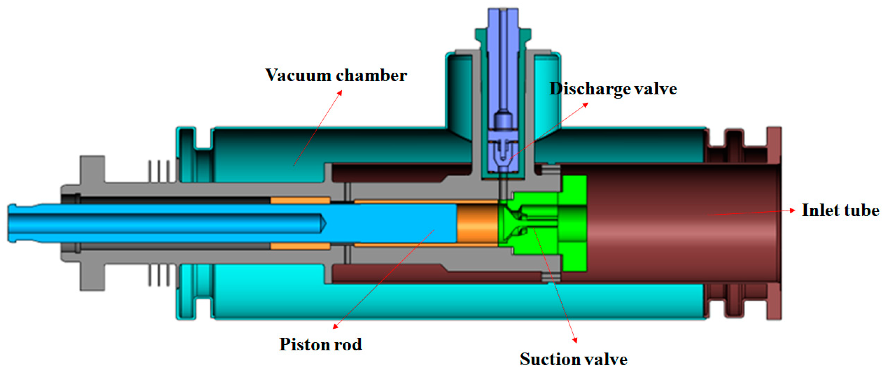
The schematic diagram of the fluid end of a reciprocating multiphase pump is shown in Figure 2. The combined action of several components, especially the movement of the piston and valve, directly affects the operation of the reciprocating multiphase pump.
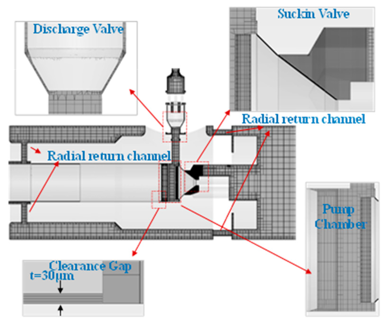
PumpLinx includes an automated mesh generator that facilitates the generation of high-quality meshes that can be efficiently solved by CFD solvers. The mesh generator uses a proprietary geometry conformal adaptive binary tree (CAB) algorithm, which generates Cartesian meshes in a volume domain consisting of closed surfaces. Near geometric boundaries, CAB automatically adjusts the mesh to fit geometric surfaces and geometric boundary lines. To accommodate critical geometric features, CAB automatically resizes the mesh by continuously splitting the mesh, which is the most efficient way to resolve detailed features using the smallest mesh. The binomial tree Cartesian mesh has the advantages of fast generation, simple operation, better computational speed and accuracy than the tetrahedral mesh, and reduced geometric trimming effort. The created mesh is shown in Figure 3.
A four-layer mesh was created for the geometry of the sealing area between the piston and the inner wall surface, using PumpLinx’s Clearance Gap mesh, with a total thickness of 30 microns for the sealing gap between the piston and the inner wall surface.
The global grid size is 0.001 m, the minimum grid size is 7 × 10⁵ m, and the number of grids is 1,994,603. In order to verify grid independence, we set the global grid size to 0.0008 m and 0.0005 m and the minimum grid size to 5 × 10⁵ m and 3 × 10⁵ m. As shown in Figure 4, the pressure variation in the liquid cylinder with three different densities of the grid is essentially the same, which means that the global grid size of 0.001 m can meet the simulation accuracy requirements.
PumpLinx has built-in templates to quickly complete the meshing of each motion region and use the templates to define the motion of the piston, suction valve, and discharge valve. Further dynamic meshing techniques are used based on the motion boundaries. The faces intersecting the valve plate and the piston end are defined as corresponding deformations, and the fluid areas near them are automatically re-engaged and updated at each time step. The templates with the moving parts of the valve are modeled using the translational degrees of freedom, including valve mass, spring stiffness, preload, initial displacement, etc.

2.3. Numerical Methods and Boundary Conditions

The turbulence models provided by PumpLinx include the standard k-ε model and the RNG k-ε model [22]. Since the RNG k-ε model takes into account turbulent vortices, it has higher confidence and accuracy than the standard k-ε model and is therefore more suitable for simulating the flow in a compressed cavity. The RNG k-ε turbulence model is used for the simulations in this paper, and the pressure–velocity coupling is performed by the pressure-implicit operator partitioning (PISO) algorithm [23]. The momentum equation, turbulent kinetic energy equation, and dissipation rate equation are discretized using the second-order windward method.
For the calculation model of discharge and suction valves applied in the closure model, the principle of the closure model is that when the combined force on the spool is not enough to lift the spool, the numerical method will interrupt the numerical calculation in the grid at the gap to achieve the purpose of “cut-off”, which is more consistent with the real situation and can more accurately simulate the pressure field before and after the valve. The flow calculation of the pump valve system is more accurate, and by applying the closure model, the simulation of the suction and discharge stroke of the pump valve system can be carried out normally, and the simulation results of the complete stroke of the pump valve can be obtained.
The reciprocating pump medium is compressible liquid hydrogen, and the compressibility of liquid hydrogen is large. Take 25 K liquid hydrogen as an example, when the pressure increases from 0.3 MPa to 45 MPa, the density increases from 64.701 kg/m3 to 92.085 kg/m3, an increase of 42.3%; therefore, it is necessary to further improve the compressibility parameters of liquid hydrogen to make the simulation results closer to the actual situation. The bulk modulus represents the pressure required to produce a unit relative volume contraction, i.e., the relationship between the density and pressure of the reaction medium, which is calculated by the following defined equation.
K = ρ d P d ρ
The medium is set to be compressible, and the initial density is 70.85 kg/m3. The bulk modulus of liquid hydrogen is calculated as K = 3.15 × 10⁷ Pa.
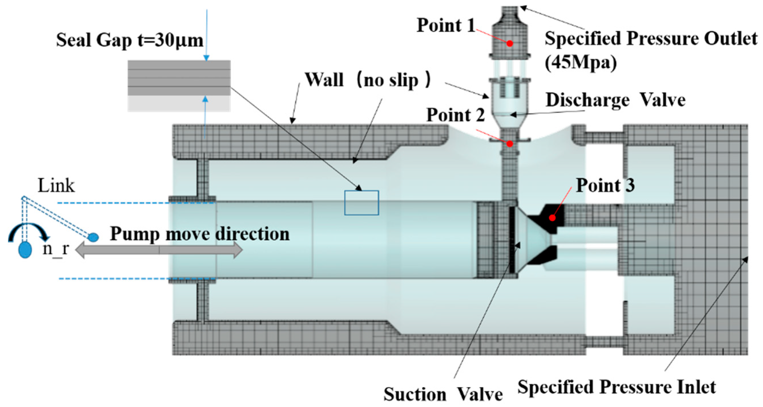
For the actual operation of the reciprocating multiphase pump, the boundary conditions are set as suction pressure, discharge pressure, and no-slip condition applied to the pump chamber wall, and the boundary conditions are set in Figure 5. The flow of numerical simulation starts from the inlet, the initial time step is set to 0.0002 s, and the residual velocity is set to 10−3. With the start of iterative calculation, the time step can be adjusted according to the grid quality and convergence.

2.4. Simulation Study Content and Valve Parameter Setting

2.4.1. Simulation Research Content

The main research content of this paper is divided into two parts. Firstly, the coupling relationship between the dynamic characteristics of the suction and discharge valves of the high-pressure liquid hydrogen reciprocating pump and the crank angle, piston displacement, and pressure in the liquid cylinder is studied. Secondly, the influence of the spring stiffness and preload of the suction and discharge valves on the dynamic characteristics of the valves is studied, including the valve hysteresis angle, maximum lift, and oscillation.

2.4.2. Valve Parameter Setting

According to the design of the suction valve and discharge valve spool of this high-pressure liquid hydrogen pump, the mass of the suction valve spool is 0.04 kg, and the mass of the discharge valve spool is 0.058 g.
According to the force analysis, for the suction valve, the spring preload force should not be too large, while the spring preload force for the discharge valve should not be too small, mainly for the following reasons:
(1)
In the expansion stroke, both the suction valve and the discharge valve are closed, and the pressure of liquid hydrogen in the compression chamber needs to be lowered to below the inlet pressure. When the sum of the pressure in the compression chamber and the spring preload is balanced with the inlet pressure, the suction valve will be opened; when the pressure in the compression chamber is too large, it will increase the opening hysteresis angle of the suction valve and affect the normal inlet; when the pressure in the compression chamber is too small, it will easily lead to the vaporization of liquid hydrogen.
(2)
In the discharge stroke, the suction valve is closed, the discharge valve is opened, and the discharge valve is balanced by the spring force and the hydraulic force. At the end of the discharge stroke, if the spring force of the discharge valve is too small, it will reduce the closing speed of the discharge valve and lead to an increase in the closing hysteresis angle, which will increase the amount of liquid hydrogen in the compression chamber when the discharge valve is completely closed and then reduce the amount of liquid hydrogen feeding during the weekly period.
Therefore, the preload force of the suction valve spring should be set low, and the preload force of the discharge valve spring should be set high to ensure the pressurization efficiency of the high-pressure liquid hydrogen pump. At the same time, it is necessary to study the effect of oscillation characteristics of the suction valve due to its small spring preload force, which is influenced by inertia force during opening and closing. The valve spring parameter setting is shown in Table 2.

3. Discussion of Results

3.1. Coupling Analysis of Pump and Valve Dynamic Characteristics

3.1.1. Flowfield Analysis of the Pressurization Process

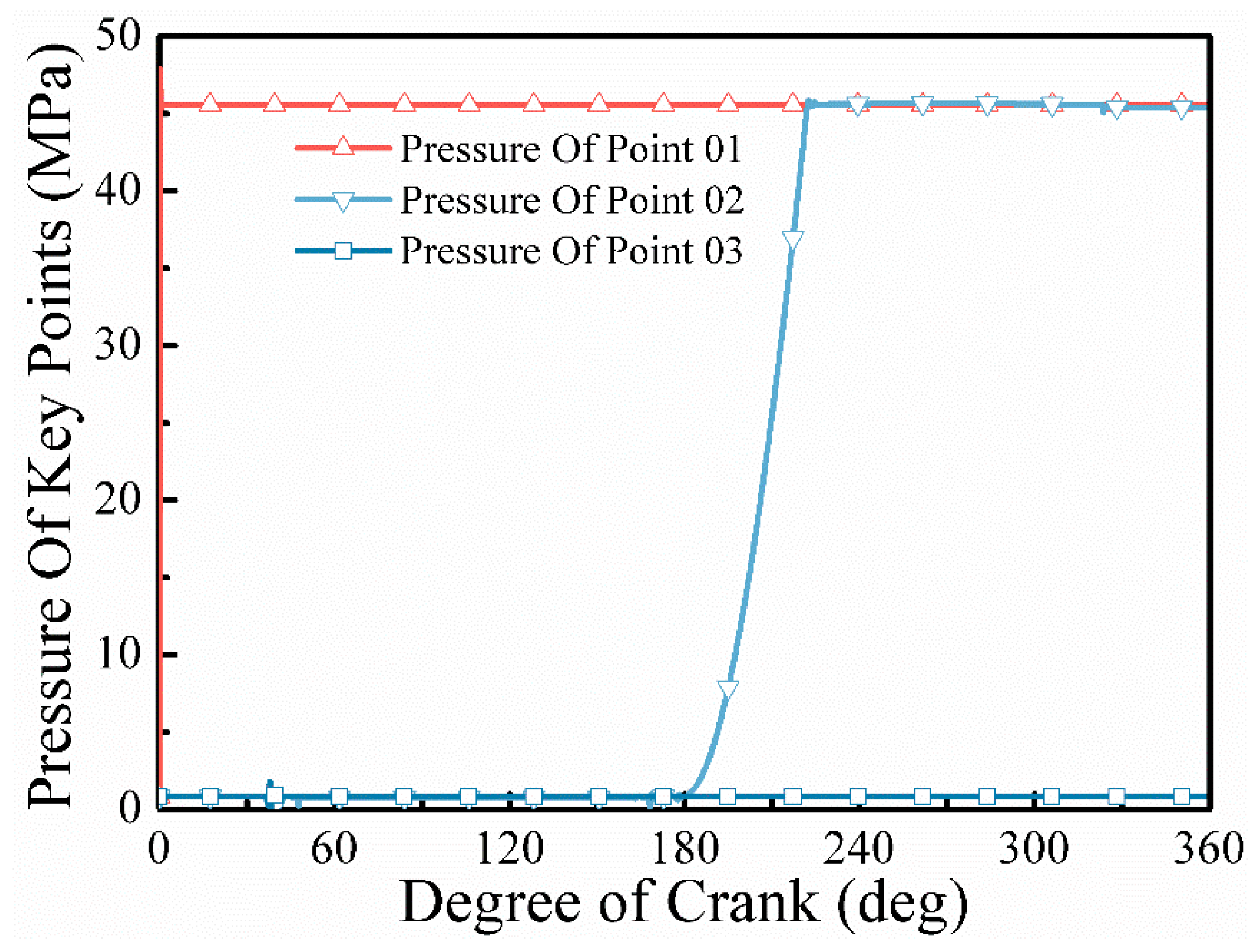
Figure 6 shows the pressure curves of three pressure monitoring points at different cranking angles. Point 1 is the pressure measurement point after the discharge valve, point 2 is the pressure measurement point before the discharge valve, and point 3 is the pressure measurement point before the suction valve. As can be seen in Figure 6, since the boundary conditions set the outlet back pressure to 45 MPa and the inlet pressure to 0.3 MPa at the reservoir pressure, the pressure value at point 1 rises rapidly to the set pressure value after the start of the calculation, and for point 3, the inlet low-pressure state of 0.3 MPa is maintained all the time, and the pressure value at point 3 does not rise with the pressure in the pump chamber, indicating the implementation of the suction valve area closure model. For the pressure at point 2, which is located in front of the discharge valve, the pressure value is 0.3 MPa at the beginning of the calculation due to the same closure model applied to the discharge valve, and the pressure in the pump chamber decreases as the crank angle increases. After the crank angle exceeds 180°, the reciprocating pump enters the compression stroke, and as the crank angle increases, the volume of the pump chamber decreases, resulting in a gradual increase in the pressure in the pump chamber. It can be seen through the No. 2 monitoring point that the crank angle is 180–210°; with the increase in crank angle, the pressure of the No. 2 monitoring point rapidly increases, and the pressure gradient gradually increases, in line with the law of motion of the pump head; at the crank angle of about 210°, the pump cavity reaches the rated pressure of 45 MPa, the pressure balance before and after the discharge valve, as the crank angle continues to increase, and the spool of the discharge valve opens. As the crank angle continues to increase, the spool of the discharge valve opens, and the discharge valve flows.
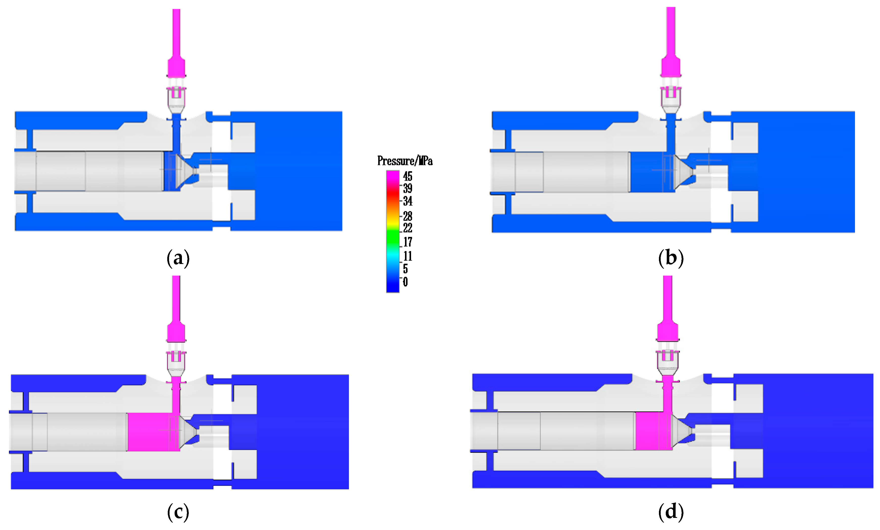
Figure 7 shows the pressure cloud diagram of the liquid hydrogen flowfield under four cranking angles, at the cranking angle of 0°–180° for the piston stretching stroke and 180°–360° for the piston compression stroke. From the pressure cloud diagram of the flowfield, it can be seen that in the piston stretching stroke of 40° and 110° angles, the liquid cylinder is a low-pressure area, and the high-pressure state is always maintained after the discharge valve, which also confirms the application of the closure model of the discharge valve. In the piston compression stroke, as the piston compresses the pump chamber to the right, the volume of the pump chamber decreases, and the pressure gradually increases until the pressure in the pump chamber overcomes the preload force of the discharge valve spring, the liquid hydrogen flows out through the discharge valve, and at the 220° and 280° turning angles in the discharge stroke, the pump chamber reaches a high pressure of more than 45 MPa, and the pressure in front of the suction valve at this time still maintains a low-pressure state of 0.3 MPa, indicating that the suction valve did not produce leakage and the closure model of the suction valve was also effective.

3.1.2. Coupling Analysis of Pump Valve Displacement and Piston Displacement

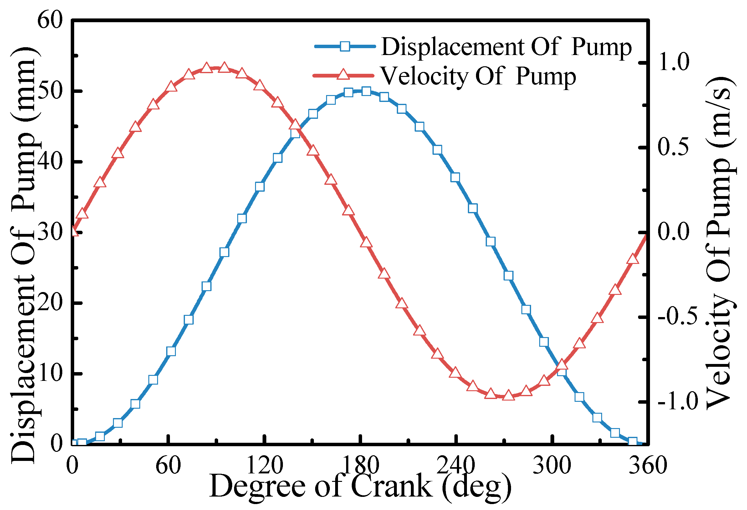
When the crank turning angle is 0°, the piston starts to move to the left, and the volume of the liquid cylinder becomes larger; when the crank turning angle is 180°, the piston starts to compress to the right, and the volume of the liquid cylinder becomes smaller. The relationship between crank angle and piston displacement is shown in Figure 8.
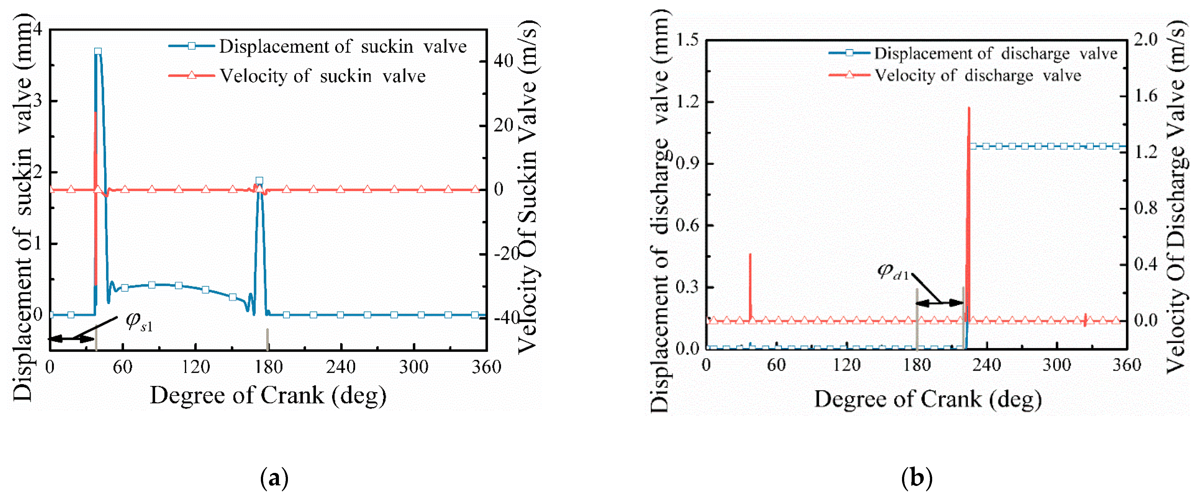
The length of one reciprocating cycle of the high-pressure liquid hydrogen pump is 0.162 s, and the piston is compressed to the maximum stroke as the initial point of one cycle. Discharge stroke: when the pressure inside the cylinder rises to a level greater than the pressure outside the discharge valve, the discharge valve opens and discharges the high-pressure liquid hydrogen. The displacement and speed of the suction and discharge valves are coupled with the crank angle as shown in Figure 9.
In the simulation results of the whole process of this model, the hysteresis angle of the suction valve and the hysteresis angle of the discharge valve are observed. Figure 10 shows the velocity curve of the suction valve spool displacement, from which it can be seen that when the crank turning angle is about 40°, the suction valve opens, and the spool displacement produces a large fluctuation, corresponding to the abrupt change in the velocity curve, the maximum lifting height reaches 3.6 mm, and the stable lifting height of the spool is about 0.45 mm. According to the definition of the hysteresis angle, the hysteresis angle of the suction valve opening is about 40°; because the setting of the spring stiffness is small, the hysteresis angle for the closing of the suction valve is almost non-existent, i.e., after the crank angle reaches 175°, the suction valve spool quickly falls back, and when the crank angle reaches 180°, the suction valve has been completely closed. Figure 10 shows the displacement and velocity curve of the discharge valve spool. From the figure, we can see that when the crank turning angle reaches 220°, the discharge valve spool lifts up, and the flow channel is smooth, and from the displacement curve of the discharge valve spool, we can see that the hysteresis angle of the discharge valve opening is about 40°, which is comparable to the opening hysteresis angle of the suction valve.

3.1.3. Coupling Analysis of Pump Valve Dynamic Characteristics and Forces

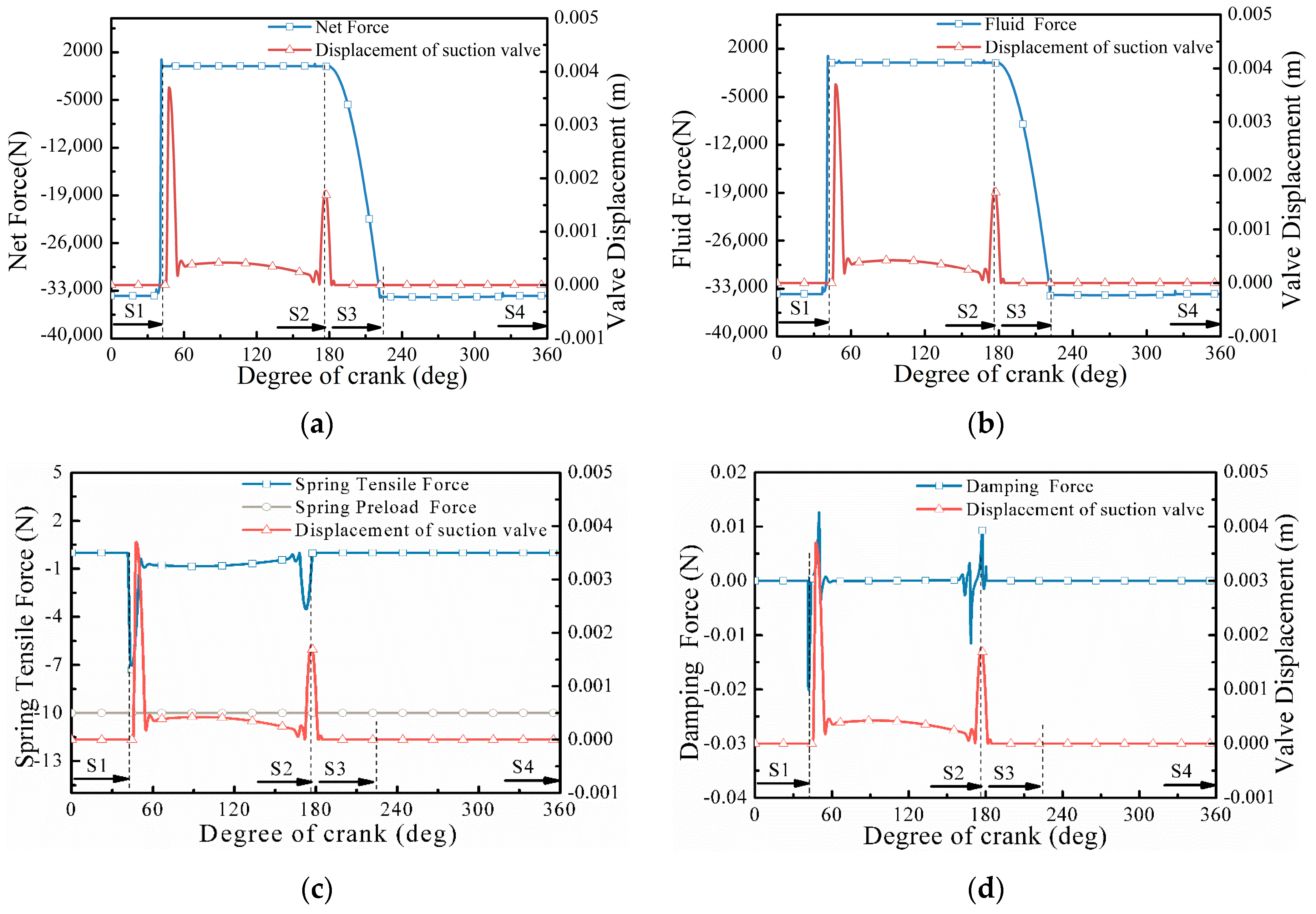
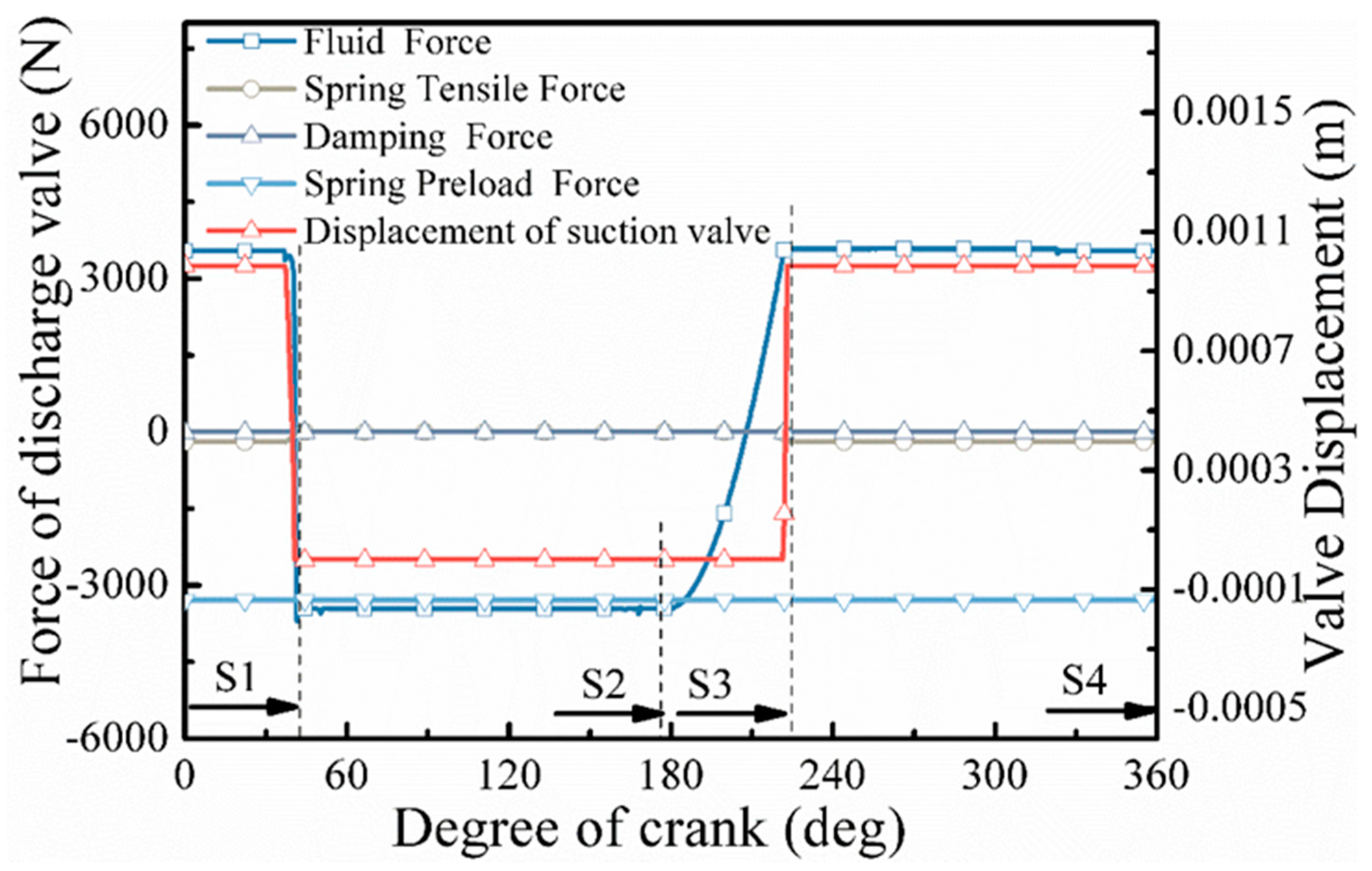
The forces on the suction valve during the operation of the high-pressure liquid hydrogen pump include the combined force, spring force, hydrodynamic force, and damping force. The spring force includes the spring preload force and the force due to spring expansion and contraction. The magnitude of the combined force is equal to the pressure on the sealing surface of the valve seat when the valve is closed and is the inertia force on the valve spool when the spool is opened instantaneously, with the opposite direction. The coupling of the combined force, spring force, hydraulic force, and damping force with the displacement curve of the suction valve is shown in Figure 9.
It can be seen that the suction valve is mainly subject to the spring preload force and the hydraulic force during the expansion stroke, and the valve opens when the hydraulic force decreases to the same level as the spring preload force. At the beginning and end of the suction stroke, the flowfield near the spool changes drastically, causing obvious fluctuations in the hydrodynamic force on the spool, with the amplitude reaching 900–1000 N, which is much larger than the spring preload force, and finally manifesting as violent oscillations of the spool displacement curve. When the crank angle is 180°, the fluid intake stops, and the suction valve closes under the action of hydraulic force and enters the boost stroke. When the hydraulic force increases to the maximum value, it enters the discharge stroke, and the combined force is the sealing pressure of the pump valve. Damping force only exists at the moment of opening and closing of the suction valve, and the value is very small, which essentially has no effect on the dynamic characteristics of the suction valve. The inertia force reaches nearly 1000 N at the moment of opening the suction valve, which is much larger than the spring preload force and thus is a large oscillation phenomenon when the suction valve is opened and closed.
The coupling of each force on the discharge valve and the displacement curve of the discharge valve are shown in Figure 11.
It can be seen that the dynamic characteristics of the discharge valve and the force coupling relationship are roughly the same as those of the suction valve, but due to the higher preload of the discharge valve, there is no obvious oscillation phenomenon.

3.2. Effect of Pump Valve Spring Stiffness and Preload Force

3.2.1. Effect of Suction Valve Spring

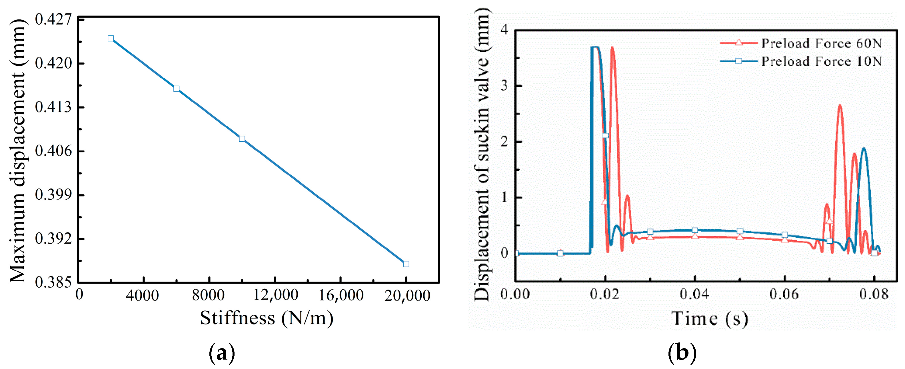
From the simulation results, the suction valve spring preload force is 10 N, the spring stiffness is 2000 N/m, 6000 N/m, 10,000 N/m, and 20,000 N/m, the opening and closing hysteresis angles of the suction valve and the degree of spool oscillation do not change much, the opening hysteresis angle of the suction valve is about 40°, and the closing hysteresis angle is about 1°. The spring stiffness of the suction valve mainly affects the lift of the spool in the inlet stroke. The spool of the suction valve in the stable opening stage has no inertia force and is balanced by the hydraulic force and spring force. The maximum lift of the stable opening stage of the suction valve under different spring stiffness of the suction valve is shown in Figure 12a.
As can be seen from Figure 12a, the displacement of the stable opening stage of the suction valve is below 0.5 mm, and the maximum displacement of the stable opening stage is smaller as the spring stiffness of the suction valve becomes larger, which is consistent with the theoretical analysis.
The spring stiffness is set to 2000 N/m, and the spring preload force is 10 N and 60 N, respectively. If the displacement of the suction valve is 0.5 mm, the increased spring force due to the opening of the suction valve is about 1 N, which is much smaller than the set preload force of the suction valve; thus the preload force has the main influence on the dynamic characteristics of the suction valve.
As can be seen from Figure 12b, the preload force of the suction valve has a greater influence on the oscillation of the suction valve when it is just opened and about to be closed. When the preload force of the suction valve is 10 N, the suction valve produces 1~2 oscillation collisions with the suction valve seat when it is opened and closed; when the preload force of the suction valve is increased to 60 N, the oscillation effect of the suction valve is obvious, and the number of oscillation collisions increases to 3~4. If the oscillation of the spool of the suction valve is too large, it will easily lead to an increase in the wear of the sealing surface of the spool and the valve seat and affect the sealing effect, and the frequent oscillation will easily cause the instability of the flowfield before and after the suction valve; therefore, it is necessary to limit the preload force of the suction valve so that it is not too large.
At the same time, the preload force of the suction valve has a significant impact on the maximum displacement of the suction valve in the stable opening stage. When the preload force of the suction valve is 10 N, the maximum displacement of the suction valve is 0.425 mm; when the preload force of the suction valve is 60 N, the maximum displacement of the suction valve is 0.3 mm. The larger the preload force of the suction valve, the smaller the maximum lift of the stabilized stage of the suction valve, which is consistent with the theoretical analysis.

3.2.2. Effect of Discharge Valve Preload Force

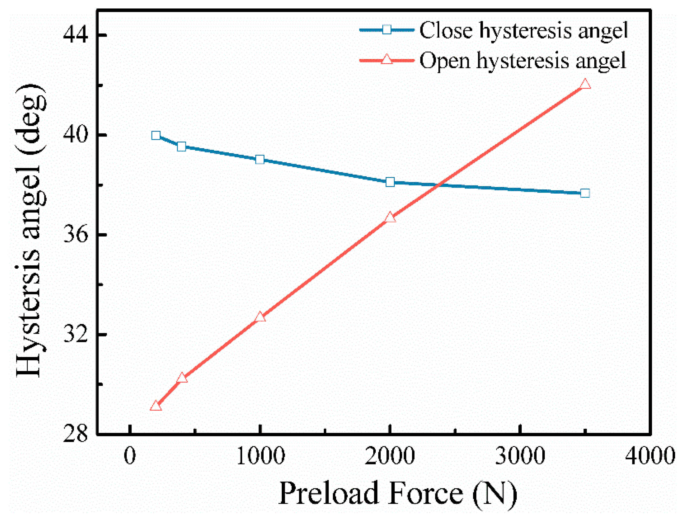
The greater the preload force, the greater the pressure difference between the inside and outside of the valve, and the greater the maximum pressure in the compression chamber, and thus the greater the opening lag angle of the valve; the closing lag angle is affected by the lift and spring force of the valve spool. The smaller the lift of the spool and the greater the spring force, the faster the discharge valve closes and the smaller the closing lag angle is.
Set the spring stiffness of the discharge valve to 1 × 10⁵ N/m and the preload force to 200 N, 400 N, 1000 N, 2000 N, and 3500 N and obtain the discharge valve hysteresis angle as shown in Figure 13.
As can be seen from Figure 13 (the limit value is probably too small), the opening hysteresis angle is about 30~40°, and the closing hysteresis angle is about 40°; as the preload force of the discharge valve increases, the opening hysteresis angle of the discharge valve increases significantly, and the closing hysteresis angle decreases slightly, which is consistent with the theoretical analysis.

4. Experimental Design and Results Validation

4.1. Test System and Results

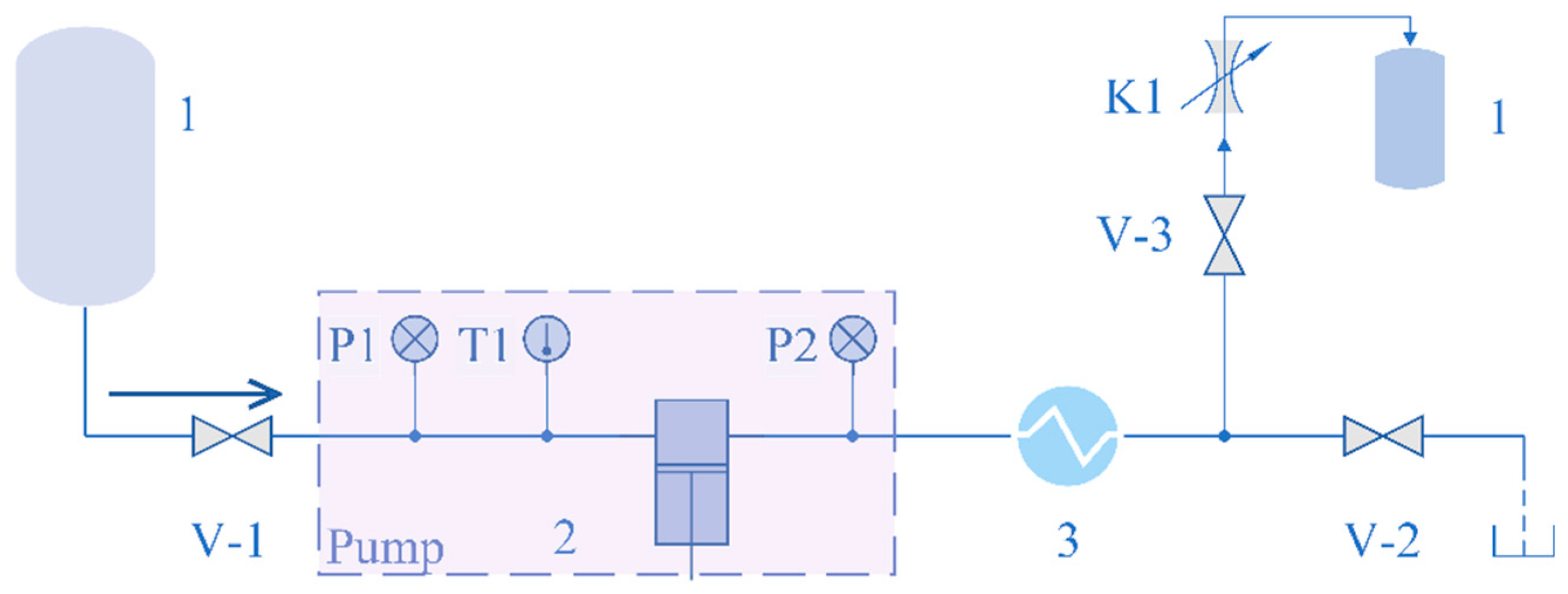
The liquid hydrogen pump test system is shown in Figure 14. Using the liquid hydrogen pump after the vaporizer and its outlet pipe closed cavity as the charging load, the data curve of pump outlet pressure versus time under different working conditions is obtained so as to obtain the highest boost pressure value of the liquid hydrogen pump.
Before the booster test of the liquid hydrogen pump, system commissioning is carried out, including unit test, cleanliness check, room temperature gas tightness check, system replacement, liquid nitrogen freezing test, etc. After liquid hydrogen is filled and pre-cooled, the pump is started.
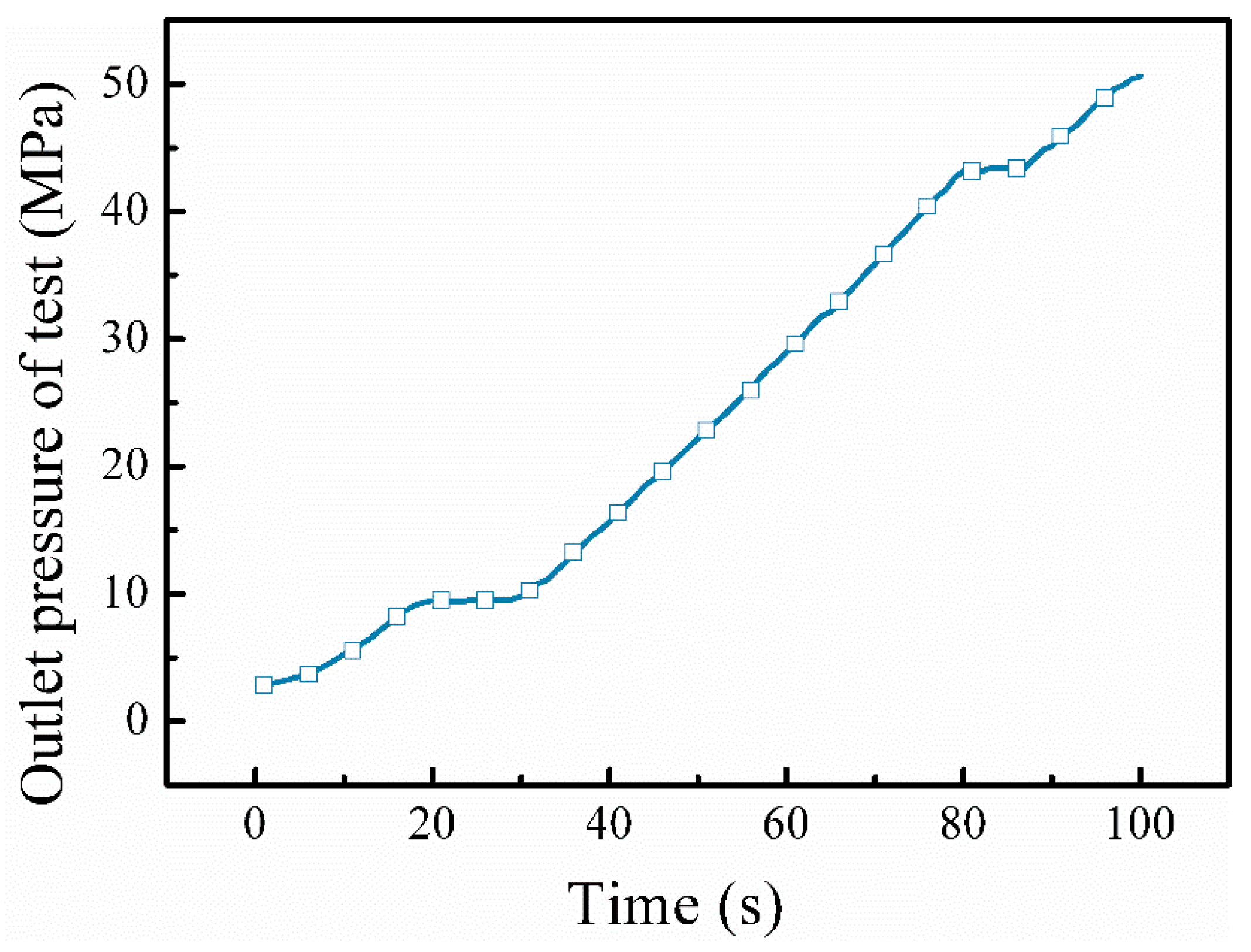
The high-pressure liquid hydrogen pump was tested at the Beijing Aerospace Experimental Technology Research Institute, and the maximum boost pressure reached 50.63 MPa. Figure 15 is a picture of the pump body during the pressurization test of the liquid hydrogen pump, and the boost curve is shown in Figure 16.

4.2. Simulation and Results of Pressurization Process

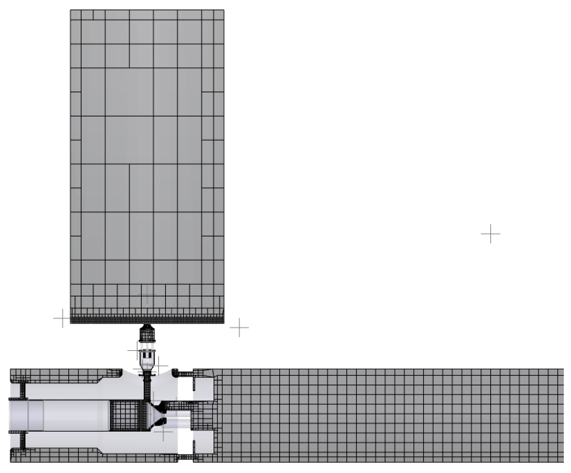
The total volume of the post-pump vaporizer and piping is calculated to be 8 L, which is equivalent to a cylindrical cavity after the pump discharge valve, and a PumpLinx simulation model is established as shown in Figure 17.
Since the post-pump cavity is not adiabatic, the piping and vaporizer structure absorbs a lot of heat during the pressurization process of liquid hydrogen, which makes the temperature of liquid hydrogen in the post-pump cavity rise rapidly and become supercritical hydrogen, and the pressure increases. Therefore, the measured post-pump pressure is equal to the simulated post-pump chamber pressure plus the pressure increase due to heat absorption.

4.2.1. Analysis of Experimental Pressure Increase Results

From Figure 18, it can be observed that there is a small pressure decrease at the end of each boosting cycle, which is due to the high-pressure backflow caused by the lag in closing the discharge valve. With the same booster time as the 10–30 MPa test, the full process simulation time is 31 s, and the simulated post-pump chamber pressure is increased from 10 MPa to 23.55 MPa.

4.2.2. Calculation of Pressure Rise Due to Heat Absorption

Since the liquid hydrogen pressure increase due to heat absorption is not considered in the small volume chamber boosting simulation, a thermodynamic calculation is required to correct the liquid hydrogen boosting pressure. Based on the actual piping and carburetor structure parameters behind the pump, the convective heat transfer heat flow rate is obtained as follows.
q = h A ( T 2 T 1 )
where q is the total heat flow rate after the pump; h is the natural convective heat transfer coefficient between the vaporizer tube and air, and the natural convective heat transfer coefficient of 304 stainless steel is taken as 4.87 W / ( m 2 K ) ; T 2 T 1 is the temperature difference between the air and the vaporizer tube wall, and the average temperature of the middle tube wall of the vaporizer is 5 °C according to the test measurement, therefore the temperature difference is taken as T 2 T 1 = 20 K ; A is the surface area of the vaporizer, which is calculated according to the following formula.
A = π D L + 2 n H L
where D is the carburetor tube diameter, D = 0.008 m ; L is the total length of the carburetor, L = 167 m ; n is the number of fins, n = 4 ; H is the height of fins, H = 0.01 m .
The calculation gives A = 60.7 m 2 , q = 5912 W .
The heat absorbed by the vaporizer is converted into the internal energy and pressure energy of liquid hydrogen, and the energy relationship is as follows.
q t = C V m Δ T + Δ P V
m = ( ρ 2 ρ 1 ) V
where t is the time used to increase the pressure from 10 MPa to 30 MPa, measured by the test t = 31 s ; C V is the constant pressure heat capacity of supercritical hydrogen, C V = 8030 J / ( kg K ) ; m is the mass of liquid hydrogen flowing into the vaporizer; ρ 1 and ρ 2 are the densities of supercritical hydrogen at 10 MPa and 30 MPa, ρ 2 ρ 1 = 17.6 kg / m 3 ; Δ T is the temperature rise of liquid hydrogen flowing into the vaporizer, the inlet temperature of the tube wall is −116 °C, and the outlet temperature is 11 °C, Δ T = 127 K ; Δ P is the pressure rise of supercritical hydrogen due to heat transfer; V is the vaporizer volume, V = 0.008 m 3 .
The calculation gives Δ P = 4.96 MPa .
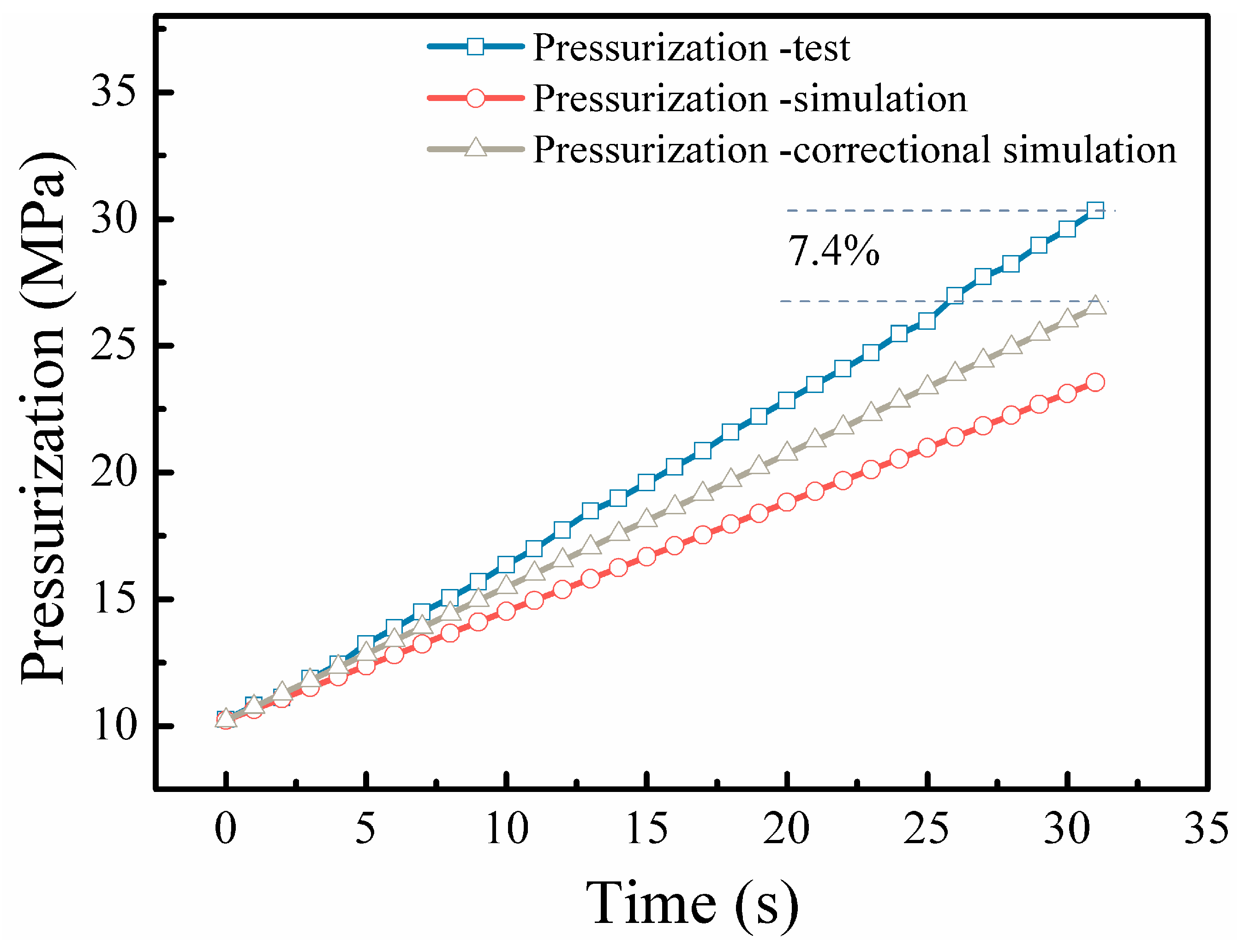
The pressure in the capacitor cavity was pressurized for 31 s through simulation, and the pressure increase due to heat transfer was superimposed to obtain the modified simulation pressurization curve. The results were compared with the experimentally measured pressurization curve and are shown in Figure 19.
Analysis of the simulated boosting curves compared with the experimental boosting curves shows that the error between simulated and experimental boosting is 7.4%, which verifies the feasibility of the method in this paper and meets the accuracy of engineering applications. The reason for the error may be the complexity of the nature of liquid hydrogen and supercritical hydrogen and that the simulation error of the flowfield caused by the multiphase flow is not considered.

5. Conclusions

The pump valve system of high-pressure liquid hydrogen reciprocating pump relies on fluid pressure difference and spring force together to realize the automatic opening and closing of the valve, and there is a strong complex coupling relationship between the motion law of the valve spool and the unsteady flow in the valve gap. In this study, by combining the dynamic mesh technology and the analysis method of coupling the spool motion with the flowfield, a full-flow unsteady flowfield simulation model was established for the fluid end of a high-pressure liquid hydrogen reciprocating pump, and the influence of valve spring stiffness and preload force on the spool motion was further studied, with the following main findings:
(1)
By considering the leakage between the piston and the cylinder wall and the valve closure model, an unsteady simulation model of the reciprocating pump valve fluid end system was established, which can simulate the motion law of the suction and discharge valves more accurately.
(2)
The opening hysteresis angle is about 40° for both the suction and discharge valves, and the opening hysteresis effect is obvious. In the four strokes of reciprocating pump operation, the hydrodynamic force on the surface of the suction spool gradually decreases to zero in the expansion stroke, after which the suction valve opens, and the spring force gradually increases. In the suction stroke, the suction spool hydraulic force and spring force remain unchanged, and the valve opening degree remains unchanged. In the compression stroke, the suction valve closes first, and its surface hydrodynamic force gradually increases; meanwhile, the surface hydrodynamic force of the discharge valve gradually increases. In the discharge stroke, the spring force and hydrodynamic force on the valve spool remain unchanged.
(3)
For the suction valve stiffness in the range of 2000–20,000 N/m, as the stiffness increases, the maximum lift of the stable opening stage of the suction valve is smaller. The preload force of the suction valve mainly affects the degree of oscillation in the opening and closing stages of the suction valve. In the range of 10–60 N for the preload force of the suction valve, the larger the preload force is, the more obvious the effect of oscillation of the suction valve is. As the preload force of the discharge valve increases, the opening hysteresis angle of the discharge valve increases significantly, and the closing hysteresis angle decreases.
(4)
By comparing the simulation model with the test, the error between the boosting speed of the simulation model and the test boosting speed is 7.4%, which verifies the effectiveness of the method in this paper and can meet the accuracy of engineering applications.

Author Contributions

Data curation, X.S.; Investigation, N.Q.; Methodology, R.L. and P.J.; Project administration, R.L.; Resources, W.G.; Software, N.Q. and X.S.; Validation, N.Q.; Visualization, X.S.; Writing—original draft, N.Q. and X.S.; Writing—review & editing, R.L., P.J. and W.G. All authors have read and agreed to the published version of the manuscript.

Funding

This research was funded by Beijing Science and Technology Plan Project (Z19110900460000).

Institutional Review Board Statement

Not applicable.

Informed Consent Statement

Not applicable.

Data Availability Statement

Not applicable.

Conflicts of Interest

The authors declare no conflict of interest.

References

  1. Wang, H. Reflections on Hydrogen Energy Development and Hydrogen Refueling Station Construction. Oil Depots Gas Stn. 2019, 28, 21–24. [Google Scholar]
  2. Brunner, T.; Kampitsch, M.; Kircher, O. Cryo-compressed hydrogen storage. Fuel Cells Data Facts Fig. 2016, 17, 162–172. [Google Scholar]
  3. Zhu, Q.; Zhu, J. The development and prospect of domestic liquid hydrogen hydrogen refueling station. Gas Heat 2020, 40, 15–19. [Google Scholar]
  4. Aceves, S.M.; Espinosa-Loza, F.; Ledesma-Orozco, E.; Ross, T.O.; Weisberg, A.H.; Brunner, T.C.; Kircher, O. High-density automotive hydrogen storage with cryogenic capable pressure vessels. Int. J. Hydrog. Energy 2010, 35, 1219–1226. [Google Scholar] [CrossRef]
  5. Petitpas, G. Simulation of boil-off losses during transfer at a LH2 based hydrogen refueling station. Int. J. Hydrog. Energy 2018, 43, 21451–21463. [Google Scholar] [CrossRef]
  6. Petitpas, G.; Simon, A.; Moreno-Blanco, J.; Aceves, S.M. Liquid Hydrogen Infrastructure Analysis; Lawrence Livermore National Laboratory: Livermore, CA, USA, 2017. [Google Scholar]
  7. Qin, N.; Brooker, P.; Srinivasan, S. Hydrogen Fueling Stations Infrastructure; Research and Innovative Technology Administration: Orlando, FL, USA, 2014. [Google Scholar]
  8. Xian, J.; Lin, Z.; Lai, Y. Hydrogen refueling station process and operational safety. Gas Heat 2017, 37, B01–B06. [Google Scholar]
  9. Furuhama, S.; Kobayashi, Y. A liquid hydrogen car with a two-stroke direct injection engine and LH2-pump. Int. J. Hydrog. Energy 1982, 7, 809–820. [Google Scholar] [CrossRef]
  10. Petitpas, G.; Moreno-Blanco, J.; Espinosa-Loza, F.; Aceves, S.M. Rapid high density cryogenic pressure vessel filling to 345 bar with a liquid hydrogen pump. Int. J. Hydrog. Energy 2018, 43, 19547–19558. [Google Scholar] [CrossRef]
  11. Gao, J.; Li, Z.; Luo, X.; Zhang, H. Numerical simulation study of the operating characteristics of axial flow control valve. Fluid Mach. 2020, 48, 12–16. [Google Scholar]
  12. Yang, Z.; Zhang, S.; Wang, M.; Zhang, D. Numerical simulation of steady-state flow field of shuttle valve based on FLUENT. Hydraul. Pneum. Seals 2017, 09, 29–32. [Google Scholar]
  13. Wu, D.; Li, S.; Wu, P. CFD simulation of flow-pressure characteristics of a pressure control valve for automotive fuel supply system. Energy Convers. Manag. 2015, 101, 658–665. [Google Scholar] [CrossRef]
  14. Zhang, M.; Feng, J.; Zhou, Z. Dynamic numerical simulation study of reciprocating pump drawing process. China Pet. Mach. 2009, 37, 42–45. [Google Scholar]
  15. Zhang, R.; Sun, P.; Fu, Y. Dynamic coupling characteristics of the flow field and spool motion of reciprocating pump valves. J. Irrig. Drain. Mach. Eng. 2021, 39, 217–223. [Google Scholar]
  16. Zhu, G.; Dong, S.; Zhang, W.; Zhang, J.; Zhang, C. Simulation of variable stiffness spring reciprocating pump cone valve and its dynamic characteristics. China Mech. Eng. 2018, 29, 2912–2916. [Google Scholar]
  17. Iannetti, A.; Stickland, M.T.; Dempster, W.M. A computational fluid dynamics model to evaluate the inlet stroke performance of a positive displacement reciprocating plunger pump. Proc. Inst. Mech. Eng. Part A J. Power Energy 2014, 228, 574–584. [Google Scholar] [CrossRef]
  18. Menéndez-Blanco, A.; Oro, J.M.F.; Meana-Fernández, A. Unsteady three-dimensional modeling of the Fluid–Structure Interaction in the check valves of diaphragm volumetric pumps. J. Fluids Struct. 2019, 90, 432–449. [Google Scholar] [CrossRef]
  19. Woo, J.; Sohn, D.K.; Ko, H.S. Analysis of stiffness effect on valve behavior of a reciprocating pump operated by piezoelectric elements. Micromachines 2020, 11, 894. [Google Scholar] [CrossRef]
  20. Yan, G.; Zhao, J.; Dong, Y. Study of reciprocating pump valve motion law. China Mech. Eng. 2004, 15, 1617–1619. [Google Scholar]
  21. Ma, Y.; Ni, Y.; Zhang, H.; Zhou, S.; Deng, H. Influence of valve’s lag characteristic on pressure pulsation and performance of reciprocating multiphase pump. J. Pet. Sci. Eng. 2018, 164, 584–594. [Google Scholar] [CrossRef]
  22. Bergmann, C.M.; Ormiston, S.J.; Chatoorgoon, V. A Comparative Study of Turbulence Models for Prediction of Upward Supercritical Fluid Flow in Vertical Rod Beam Subchannels. Nuclear Eng. Des. 2017, 322, 177–191. [Google Scholar] [CrossRef]
  23. Sharma, G.; Ghosh, S.; Karmakar, S. Computational fluid dynamic simulation of single and two-phase vortex flow—A comparison of flow field and energy separation. J. Heat Transf. 2016, 138, 082003. [Google Scholar] [CrossRef]
Figure 1. Schematic diagram of reciprocating pump hydraulic end and pump valve. (a) Simplified physical model of liquid hydrogen reciprocating pump; (b) Suction valve and discharge valve schematic.
Energies 15 04255 g001
Figure 2. High-pressure liquid hydrogen reciprocating pump hydraulic end.
Energies 15 04255 g002
Figure 3. High-pressure liquid hydrogen pump structure mesh division.
Energies 15 04255 g003
Figure 4. Grid independence verification.
Energies 15 04255 g004
Figure 5. Boundary conditions for the simulation of unsteady flowfield of reciprocating pump.
Energies 15 04255 g005
Figure 6. Pressure variation curve of flowfield at monitoring point.
Energies 15 04255 g006
Figure 7. Internal liquid hydrogen pressure diagram of reciprocating pump at different crank angles. (a) Crank angle 40°. (b) Crank angle 110°. (c) Crank angle 220°. (d) Crank angle 280°.
Energies 15 04255 g007
Figure 8. Piston displacement and velocity curve.
Energies 15 04255 g008
Figure 9. Displacement and velocity curve of suction and discharge valve spool. (a) Suction valve spool displacement velocity curve. (b) Discharge valve spool displacement velocity curve.
Energies 15 04255 g009
Figure 10. Coupling of force and the displacement curve of the suction valve. S1, expansion stroke; S2, suction stroke; S3, compression stroke; S4, discharge stroke. (a) Coupling of suction valve net force, displacement, and crank angle. (b) Coupling of suction valve hydrodynamic force, displacement, and crank angle. (c) Coupling of spring force and displacement of the suction valve with the crank angle. (d) Coupling of suction valve damping force, displacement, and crank rotation angle.
Energies 15 04255 g010
Figure 11. Coupling of force, displacement, and crank angle of the discharge valve.
Energies 15 04255 g011
Figure 12. Effect of suction valve spring. (a) Effect of spring stiffness of suction valve on maximum spool displacement. (b) Effect of the preload force of the suction valve on the degree of spool oscillation.
Energies 15 04255 g012
Figure 13. Effect of discharge valve preload on hysteresis angle.
Energies 15 04255 g013
Figure 14. Sketch of liquid hydrogen pump pressure vaporization test system. P1, P2 are pressure sensors, T1 is a temperature sensor. 1 is the liquid hydrogen storage tank, 2 is the liquid hydrogen pump, 3 is the vaporizer. V-1 is the suction valve, V-2 is the degassing valve, V-3 is the exhaust valve, and K1 is the throttling element.
Energies 15 04255 g014
Figure 15. Liquid hydrogen pump pressurization test picture.
Energies 15 04255 g015
Figure 16. Test pressure curve of liquid hydrogen pump boosted to 50.6 MPa.
Energies 15 04255 g016
Figure 17. PumpLinx simulation physical model.
Energies 15 04255 g017
Figure 18. Two-cycle simulated boost curve.
Energies 15 04255 g018
Figure 19. The test pressurization curve of 10~30 MPa and the simulated pressurization curve.
Energies 15 04255 g019
Table 1. High-pressure liquid hydrogen reciprocating pump parameters table.
Parameter NameUnitIndicators
FlowL/h1170
Discharge pressureMPa45
Rotational speedrpm370
Crank lengthmm25
Crank linkage ratio 10.8
Discharge valve sealing widthmm6.00
Discharge valve inner diametermm8.00
Outside diameter of discharge valvemm19.00
Table 2. Valve spring parameter setting.
Research ContentSpring Stiffness of the Suction Valve
(N/m)
Spring Preload of the Suction Valve
(N)
Spring Stiffness of the Discharge Valve
(N/mm)
Spring Preload of the Discharge Valve
(N)
Research Content 1Case1.12000102002000
Research Content 2Case2.12000/6000/10,000/20,000102002000
Case2.2200010/602002000
Case2.3200010200200/400/1000/2000/3500
Publisher’s Note: MDPI stays neutral with regard to jurisdictional claims in published maps and institutional affiliations.