1. Introduction
Seismic data obtained from exploration areas with strong absorption and attenuation properties feature low frequencies and weak amplitudes. In addition, the imaging results of traditional imaging algorithms, without considering the absorption and attenuation compensation in such exploration areas (such as gas-bearing reservoirs), decrease regarding resolution (Traynin et al., 2008 [
1]). To improve the imaging accuracy of this type of exploration area, the absorption and attenuation effect during the imaging process must be compensated.
The most commonly used seismic wave absorption and attenuation compensation methods include the Q deconvolution and visco-acoustic medium pre-stack depth migration (PSDM) methods. The former is used for the zero-offset seismic channel (or post-stack data), whereas the latter is used for the change in Q value and the absorption and attenuation compensation along the wave propagation path. The inverse Q migration processing of pre-stack seismic data is conducted in the following ways: Inverse Q-compensation is conducted when the upward received wavefield is extended backward, and the inverse Q-compensation is also conducted when the source wavefield is extended downward; the imaging is then conducted for the primary wave under certain imaging conditions.
Deconvolution is a standard method for improving the resolution of seismic imaging in the traditional seismic data processing. The optimal Wiener filter is a traditional deconvolution method used to identify the optimal solution regarding the least square. However, it assumes the time invariance theory. When the seismic wave propagates through an underground medium, the wavelet’s shape is time-varying. In areas with severe absorption and attenuation, the achievement of ideal results using the general Wiener deconvolution method is difficult. Futterman (1962) [
2] proposed a constant
Q medium model based on the linear absorption theory. Kjartansson (1979) [
3] introduced the frequency-dependent complex modulus to improve the linear seismic wave absorption model. In this model, absorption is proportional to a certain power of a frequency function, which better reflects the principle of causality in seismic wave absorption and attenuation. Wang (2002, 2008) [
4,
5] studied seismic wave attenuation and inverse
Q filter compensation through the numerical wavelet test, and the
Q value obtained from the Vertical Seismic Profiling (VSP) downward wavefield was applied to the surface data to improve resolution. Chopra et al. (2003) [
6] proposed a high-frequency recovery method, using the Wiener shaping filter to obtain an inverse filter operator to describe the formation absorption effect from VSP records, and applied it to the post-stack data to improve the profile resolution. The time-varying Wiener filter proposed by van der Baan (2012) [
7] can also achieve the same absorption and attenuation compensation effect as the inverse
Q filter. Braga and Moraes (2013) [
8] applied and realized the inverse
Q filtering method in the wavelet transform domain and determined the amplitude damping coefficient according to the signal-to-noise ratio of seismic data for amplitude attenuation compensation and velocity dispersion correction. Ren et al. (2007) [
9] proposed a method of
Q-compensation along the ray path defined by the root-mean-square velocity in the Common Middle Point (CMP) channel gather, which improved the deficiency of the
Q-compensation for the zero-offset seismic channel. Li et al. (2015) [
10] proposed a compensation method that can compensate the horizontal and vertical depth absorption attenuation at the same time. Starting from the absorption attenuation operator, this method separates the attenuation operator into the attenuation operator related to the horizontal and vertical absorption attenuation, respectively, and then applies the separated operator to the horizontal and vertical absorption attenuation compensation, respectively, so as to realize the absorption attenuation compensation algorithm.
Single channel inverse
Q filtering bears certain advantages, including simplicity and improved wavelet property after processing. However, the absorption and attenuation of seismic waves occur along the propagation path, as a result, a better compensation method is based on the PSDM method in visco-acoustic media (or even visco-elastic media). Mittet et al. (1995) [
11] proposed the use of the MeClellan transformation to conduct PSDM in visco-acoustic media in the frequency-space domain, which increases the calculation amount. Wang (2004) [
12] achieved PSDM imaging of visco-acoustic media for a common shot point gather.
In addition, reverse time migration (RTM) is a widely used imaging method. When RTM performs
Q-compensation migration, it is necessary to modify the two-way wave equation (Suh et al., 2012 [
13]; Dutta et al., 2014 [
14]; Zhu et al., 2014 [
15]). Chen et al. (2020) [
16] developed a robust stabilization strategy for
Q-RTM by incorporating a time-variant filter into the amplitude-boosted wavefield extrapolation step. Yang et al. (2021) [
17] developed a robust space-wavenumber compensation operator to overcome numerical instabilities for seismic data with strong high-frequency noise and applied it to visco-acoustic RTM. Fathalian et al. (2021) [
18] set up a procedure for solving the time-domain visco-acoustic wave equation for tilted transversely isotropic (TTI) media, based on a standard linear solid model and, from this, develop a visco-acoustic reverse time migration (
Q-RTM) algorithm. However, numerical solution of two-way wave equation has some problems: for example, for high-frequency data, numerical dispersion is especially difficult to overcome and so on. Sun et al. (2017) [
19] developed two attenuation compensation operators that correct for both amplitude loss and velocity dispersion in a stable manner and when applied to RTM, it leads to two kinds of
Q-compensation imaging conditions.
This paper uses the 15-degree equation in the ray-centered coordinate system. In the ray-centered coordinate system, the wavefield propagates along the ray. In isotropic media, the ray direction represents the propagation direction of seismic wave. As a result, we can carry out
Q-compensation along the propagation path of seismic wave. In addition, since the 15-degree equation in the ray-centered coordinate system is solved in the frequency-space domain,
Q attenuation and
Q-compensation can be realized as long as the real velocity is changed to complex velocity, while we need to modify the two-way wave equation accordingly for RTM. Finally, using the 15-degree equation can accurately describe the local wavefield in the beam, while the wavefield obtained by Gaussian beam is the high-frequency approximation solution of the two-way wave equation, which can not accurately describe the local wavefield (Zhang et al., 2021 [
20]).
Wang (2004) [
12] emphatically discussed the control challenge associated with amplitude compensation stability in the wavefield continuation process. This method uses the quality factor of the overlying strata of the seismic trace, where the imaging point is located to determine the total amplitude compensation of each frequency component and the amplitude stabilization compensation within the current extrapolation step. Considering that only the absorption effect of the single channel overlying strata is used, the method does not strictly follow the propagation path to compensate the absorption effect for the post-stack wavefields. In addition, although the amplitude stabilization compensation in the current extrapolation step is determined by the total amplitude compensation, the wavefield is recursively extended; therefore, the influence of stability control (lowpass gain effect) is cumulative. When the extrapolation depth is large, the amplitude compensation for the high-frequency components may be overly suppressed and thus may affect the imaging resolution and have a negative effect.
Theoretically, the inverse Q migration compensates and corrects the attenuation effect of inelastic absorption in the media in strict accordance with the wavefield propagation path. However, the compensation operator of the attenuation amplitude in the inverse Q migration increases exponentially as frequency increases, and the calculation stability issue occurs when the quality factor is small with a long extrapolation time. Two methods are commonly used to control high-frequency amplitude compensation instability—the gain cut-off frequency and stability factor methods. Both methods control the stability of the inverse Q-compensation by limiting the effective gain cut-off frequency.
In this study, based on the 15-degree equation beam propagation in the ray-centered coordinate system, absorption and attenuation compensation along the wave propagation path is conducted, offering three advantages:
- (1)
This method provides Q-compensation along the real propagation path of seismic waves in isotropic media;
- (2)
In terms of mathematical derivation, this method is simpler than the Q-compensation imaging method of RTM;
- (3)
Compared with the Gaussian beam method, this method does not introduce high-frequency asymptotic (Zhang et al., 2021 [
20]).
- (4)
Numerical experiments demonstrate the effectiveness of the proposed method.
2. Seismic Wave Absorption and Attenuation Mechanism
The acoustic and elastic wave equations are used to describe wave propagation, and seismic waves are assumed to propagate in adiabatic media—the wave continues to propagate indefinitely upon generation by a particular source. Therefore, the wave may attenuate in space as it spreads from its source, but the total energy of the particle motion remains constant.
The propagation of seismic waves in real media differs from that in an ideal medium. The seismic wave amplitude and geometric diffusion factors are attenuated, and accompanied by chromatic dispersion, resulting in a change in spectrum components and the seismic waveform. The absorption and dispersion characteristics of seismic waves in real media are closely related to physical conditions, such as material composition, saturation and porosity of rock strata; the overall effect of such absorption and attenuation can be described by a dimensionless quantity (i.e., the quality factor, Q, of medium).
To evaluate the effect of attenuation, the effect of Q in frequency domain on wave propagation can replace the real angular frequency with a complex angular frequency; the influence of Q in the wavenumber domain on wave propagation can be regarded as a substitution for the complex wavenumber of real wavenumber . In the first case, the complex angular frequency, , must have an imaginary part, ; in the second case, the complex wavenumber, , must have an imaginary part .
The complexity of real media complicates the description of absorption and attenuation of seismic waves for the viscous property of the media with a mathematical physical model. The absorption, attenuation and dispersion curves of the K-F and Kjartansson (K-J) models are the most commonly used in the compensation of absorption and attenuation in exploration seismology.
The mathematical expression of the K-J model is defined in Equations (1)–(4):
where,
represents the reference velocity and is used as the acoustic velocity;
refers to the reference frequency, which is considered to be the main frequency of the wavelet;
represents the quality factor;
is the amplitude attenuation factor;
is the loss angle;
is the real part of the complex wavenumber
; and
is the imaginary part of the complex wavenumber
.
We used the K-J model in this study. The complex wavenumber expressed in Equation (3) can be derived, and the absorption and attenuation of seismic wave propagation can be described.
Wave propagation in the absorption and attenuation media is irreversible. The absorption and attenuation compensation by the K-J model is commonly used in seismic exploration as its effects are evident. However, no strict mathematical physics theorem guarantees the absolute rationality of absorption and attenuation compensation. The effect of inverse Q filtering and the effect of absorption and attenuation compensation of PSDM are used to judge the appropriateness of the absorption and attenuation compensation.
In addition, the scattering phenomena alter the amplitude attenuation and phase change in the observed seismic waves. O’Doherty and Anstey (1971) [
21] noted that stratigraphic filtering would occur when seismic waves pass through fine stratigraphic strata, resulting in the attenuation of seismic wave amplitudes and phase changes, which vary with different offsets. However, the amplitude attenuation and phase change in the seismic waves caused by these two phenomena are not easily distinguishable. Therefore, the
Q value estimated from seismic wave amplitude attenuation should be the equivalent
Q value of these two effects.
3. Stable Inverse Q PSDM in the Ray-Centered Coordinate System
The core concept of this study is the compensation of the inelastic absorption and attenuation along the wave propagation path; therefore, the wavefield extrapolation equation in the visco-acoustic medium is generated first.
3.1. Wavefield Continuation with Attenuation Compensation in the Ray-Centered Coordinate System
The ray-centered coordinate system is centered on the ray, which is an orthogonal coordinate system at each point on the ray (Zhang et al., 2021 [
20]).
The dispersion equation (Equation (5)) of the two-way wave in the ray-centered coordinate system of the isotropic acoustic medium is expressed as follows (Cheng et al., 2012 [
22]):
According to the above expression, the real wavenumber
is replaced by the complex wavenumber
, and the dispersion equation of the two-way wave in the ray-centered coordinate system of isotropic visco-acoustic media can be obtained using Equation (6):
where
and
are the ray-centered coordinates;
is the complex wavenumber, and it is assumed to be independent of the spatial position. In addition,
Equation (6) follows the expression form of Equation (5) in the acoustic medium; however, the wavenumber changes from real to complex. There are many expressions of the complex wavenumber , and different mathematical models of absorption and attenuation can define different types of complex wavenumbers.
To obtain the wavefield compensation continuation operator in the ray-centered coordinate system, wavenumber,
, must be determined (Equation (7))
The 15-degree equation in the frequency-wavenumber domain can be expressed as Equation (8):
Substituting Equation (7) into Equation (8) yields Equation (9):
Equation (9) is the one-way wave equation in the ray-centered coordinate system, where the positive sign represents the extrapolation along the negative direction of ; the minus sign represents the extrapolation along the positive direction of .
Equation (9) can be broken down in Equations (10) and (11):
The analytic solution of the wavefield in Equation (10) can be obtained directly using Equation (12):
Equation (12) can then be substituted into Equation (11), which can be solved to control the propagation of the one-way wave in the ray-centered coordinate system. Therefore, we only numerically solve and focus on Equation (11).
Subsequently, in order to eliminate the influence of subscript “2”, we mark as .
The analytic solution of Equation (11) is Equation (13):
Therefore, the decay continuation operator is expressed by Equation (14):
Equation (14) is a wavefield attenuation continuation operator considering the attenuation effect of the absorption media.
By back propagating the attenuation continuation operator (i.e. replacing
in the right end term of equation 10 with
), the compensation continuation operator can be obtained (Zhang et al., 2010 [
23])
3.2. Finite Difference Solution of the One-Way Wave Equation in Frequency-Space Domain of the Ray-Centered Coordinate System
We considered wavefield extrapolation in the positive direction of
(equivalent to the downward wave equation in the Cartesian coordinate system) in Equation (11) as an example. To simplify the calculation, we introduce Equation (16):
To obtain the one-way wave equation in the ray-centered coordinate system, we apply the Taylor expansion of
to generate Equation (17):
Substituting Equation (16) into Equation (17) yields Equation (18):
where
.
Therefore, Equation (11) can be approximated as follows (Equation (19)):
The simplified Equation (19) can be expressed as Equation (20):
Equation (20) can be abbreviated as Equations (21) and (22):
where
Equation (23) is a derivation of the finite difference solution of Equation (21) (Ma, 1989 [
24]):
where
.
Through derivation, we have produced an implicit discretization of Equation (21).
For the wavefield continuation along the negative direction of
, Equation (22) can be revised to Equation (24):
3.3. Stability Control
According to Equation (9), the one-dimensional (1D) one-way wave equation in the ray-centered coordinate system of frequency-space domain of isotropic visco-acoustic media can be expressed by Equation (25):
which has the same form as the 1D one-way wave equation in the Cartesian coordinate system in the frequency-space domain of isotropic visco-acoustic media.
Next, we consider the positive extrapolation of to be an example of the stability of isotropic visco-acoustic media in the ray-centered coordinate system.
The wave equation along the positive extrapolation of
(downward extrapolation wavefield) is expressed as Equation (26):
The analytic solution of Equation (26) is expressed as Equation (27):
Substituting Equation (3) into Equation (27) yields Equation (28):
The specific expression of complex wavenumber (or complex velocity) is determined by the absorption and dispersion model. This study uses the K-J model, and the specific expression of this model is shown in Equations (3) and (4).
Substituting
for
in Equation (27), the expression of wavefield absorption and attenuation compensation can be expressed using Equation (29):
where
is the amplitude compensation term and
is the phase dispersion correction term, the respective expressions of which are defined in Equations (30) and (31):
Taking time (quasi-depth)
as the extrapolation step and assigning the reference velocity
of the constant
Q model yields:
where
is the amplitude compensation term and
is the phase continuation dispersion correction term whose respective expressions are defined in Equations (33) and (34):
When the
Q value is large,
. Then, the amplitude compensation operator (33) can be expressed as Equation (35):
According to Equation (34), the correction of the phase velocity dispersion effect can be completed by a phase shift, and the modulus of its correction term is a constant set to 1, making it unconditionally stable. However, Equation (35) shows that the compensation operator of the attenuation amplitude is an exponential function wherein base increases as the frequency increases. The computational stability problem occurs when the value of quality factor Q is small and the extrapolation time is large.
Considering the control issue associated with the amplitude compensation stability, the amplitude compensation cumulant should be estimated. For the wavefield extrapolation along the positive direction of (downgoing wavefield), let in Equation (33), be the receiving record, and becomes the total extrapolation time from the surface in the local beam to the current point.
The gain cut-off frequency method or stability factor method is used to control the amplitude compensation operator. The amplitude compensation operator of the gain cut-off frequency method can be expressed by Equation (36):
where
is the gain cut-off frequency. This study uses the method proposed by Bickel and Natarajan (1985) [
25] to calculate the gain cut-off frequency,
(Equation (37)):
where the gain cut-off coefficient
is a constant with a value ≥1. Wang (2002) [
4] also presents the same set of criteria for the gain cut-off frequency based on the overall characteristics of the amplitude compensation operator. The gain cut-off frequency,
, is applied to the wavefield extrapolation process of absorption and attenuation compensation for PSDM.
3.4. Inverse Q PSDM
This study briefly lists several core formulas for the PSDM of ray beams:
Source wavefield extrapolation can be expressed according to Equation (38):
where,
is the wavefield estimator projected back to the Cartesian coordinate system from the ray-centered coordinate system.
is the local wavefield at the source point.
specifies beam direction,
specifies transverse spreading range, and
represents the wavefield at a certain depth.
The wavefield extrapolation at the receiver can be expressed by Equation (39):
The meaning of each quantity in Equation (39) is similar to that of Equation (38).
The imaging formula is expressed by Equation (40):
where
is the pre-stack imaging result. The sum of the right end term of Equation (40) on the frequency component can only be conducted on the positive frequency.
As the wavefield extrapolation equation is linear, the synthesized local wavefield can be directly extrapolated by the wavefield extrapolator and the imaging results of Equation (40) can complete the finite difference PSDM of the 15-degree equation beam in the ray-centered coordinate system of the visco-acoustic media.
The vertical resolution of the seismic imaging is primarily determined by the wavelet bandwidth and the spread of the dominant frequency band. The bandwidth of the wavelet and the spread of the dominant frequency band are affected by the inelastic factors of the media in the propagation process, causing the elimination of the absorption, attenuation and dispersion of the seismic wave caused by inelastic factors in the full path from the source point to the reflection point and then to the receiver point. Compared with the general migration method, the inverse Q migration focuses on the compression of the seismic wavelet to obtain higher vertical resolution imaging results. Meanwhile, the deep seismic wave’s attenuation energy can be compensated to a certain extent.
For post-stack migration, the seismic profile is assumed to be self-exciting and self-receiving, and the upward and downward paths coincide. With inverse Q migration, the mere compensation of the upward wave is sufficient; however, the migration velocity is halved.
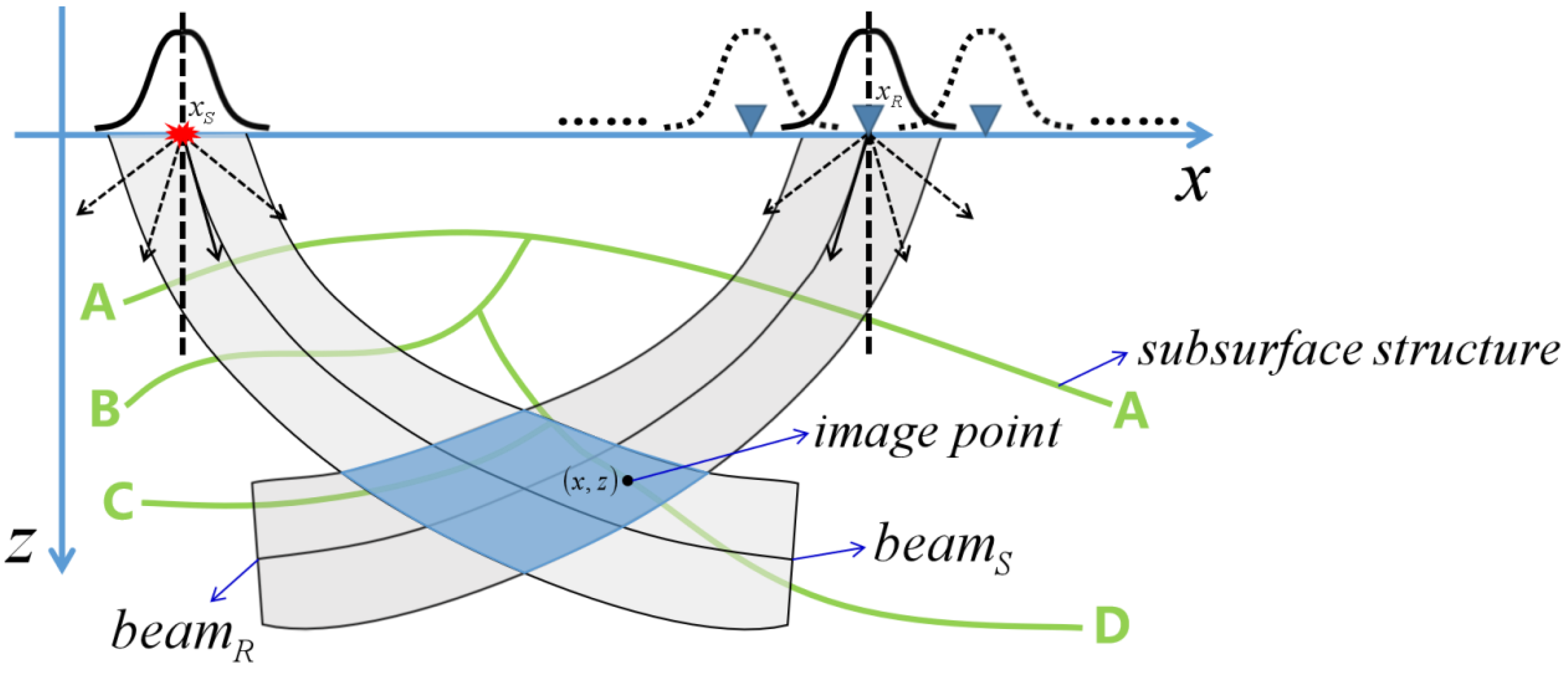
For pre-stack migration, the amplitude compensation of the upward wave extrapolation is simpler when the common shot gather migration is conducted based on the single square root operator in the ray-centered coordinate system. However, this only compensates for the attenuation and dispersion of energy absorption from the reflection point to the receiver point, whereas the attenuation and dispersion from the source point to the reflection point are not compensated. In this study, forward modeling is conducted from the source point to the reflection point without
Q, yielding wavefield
, and then conducted with
Q, yielding wavefield
. The ratio of
is the quantity of the amplitude attenuation and the dispersion of the corresponding downward local spherical wave, which is multiplied with the extrapolation result of the upward wavefield for the corresponding local spherical wave to obtain the amplitude absorption, attenuation and dispersion compensation of the two-way path (as shown in
Figure 1). Stability control involves the use of Equation (37) to calculate the appropriate gain cut-off frequency in each extrapolation step to limit the frequency involved in extrapolation.


