
Twin Shear Unified Strength Solution of Shale Gas Reservoir Collapse Deformation in the Process of Shale Gas Exploitation

Abstract
:1. Introduction
2. Materials and Methods
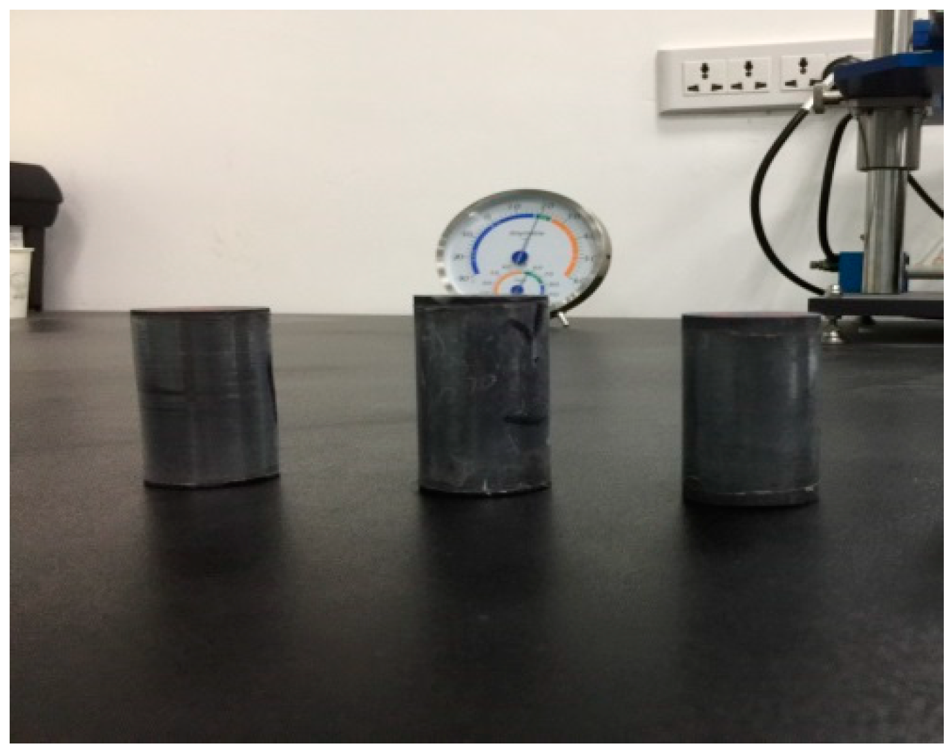
2.1. Materials
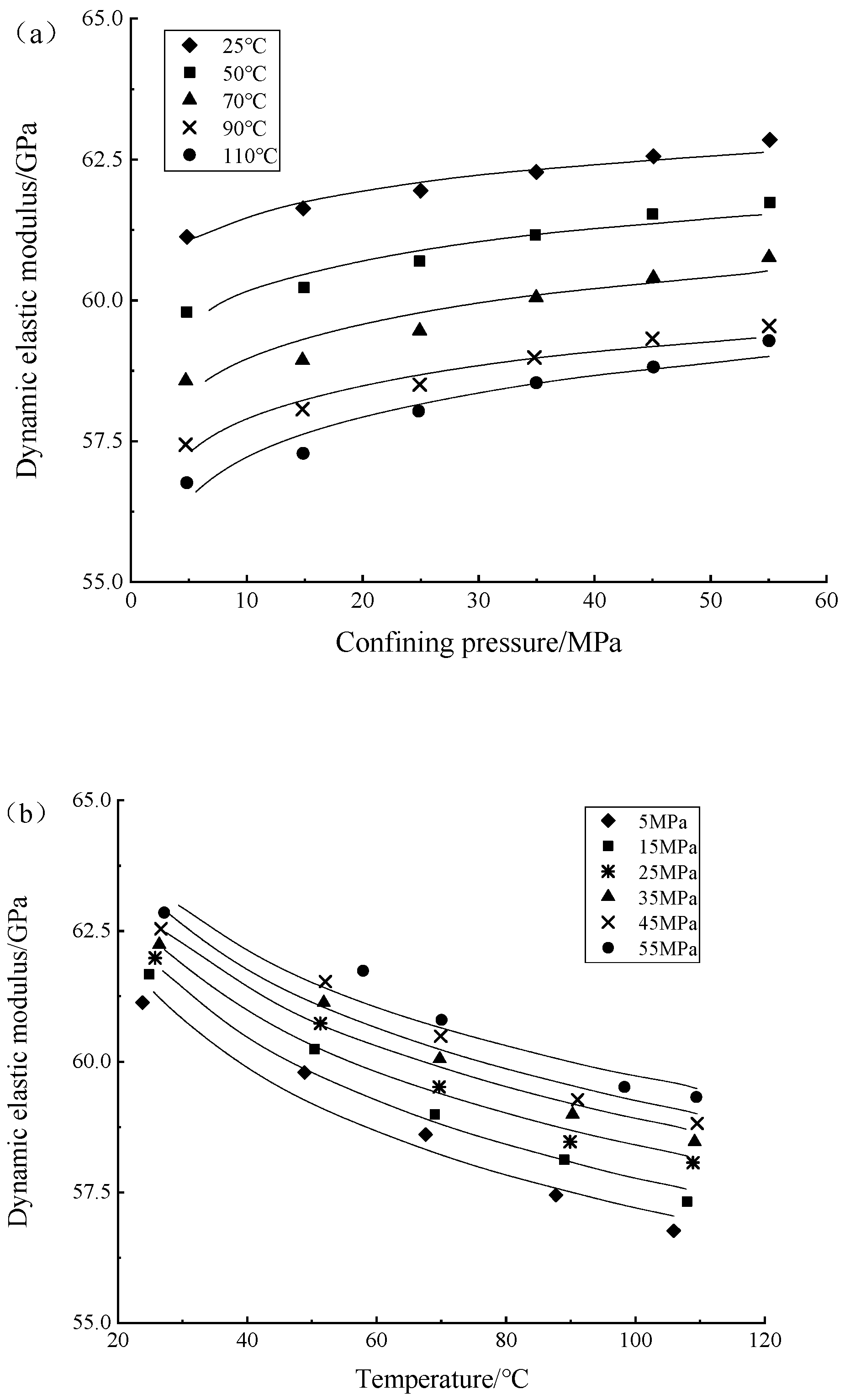
2.2. Experimental Study on Dynamic Elastic Modulus
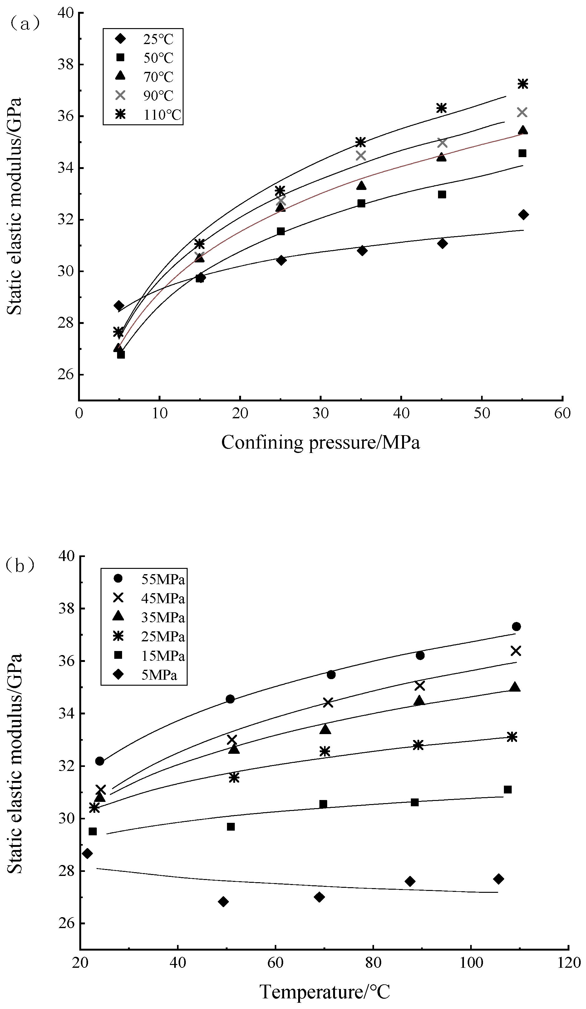
2.3. Experimental Study on Static Elastic Modulus
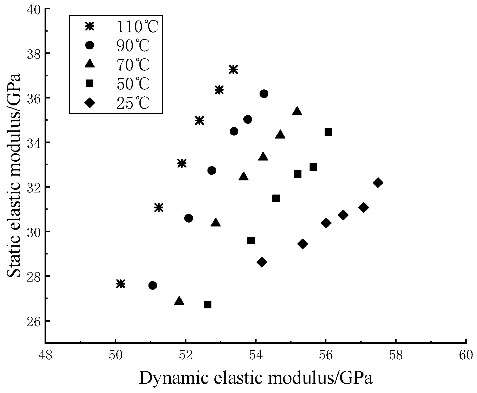
2.4. Comparison of Dynamic and Static Elastic Moduli of the Shale Specimens
3. Results
3.1. Twin Shear Unified-Strength Theory
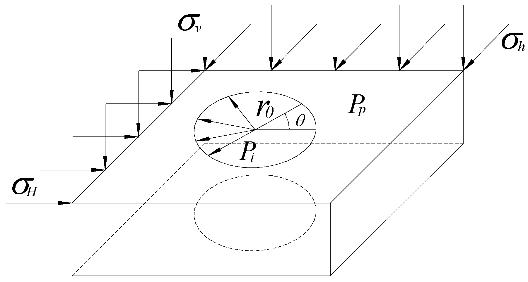
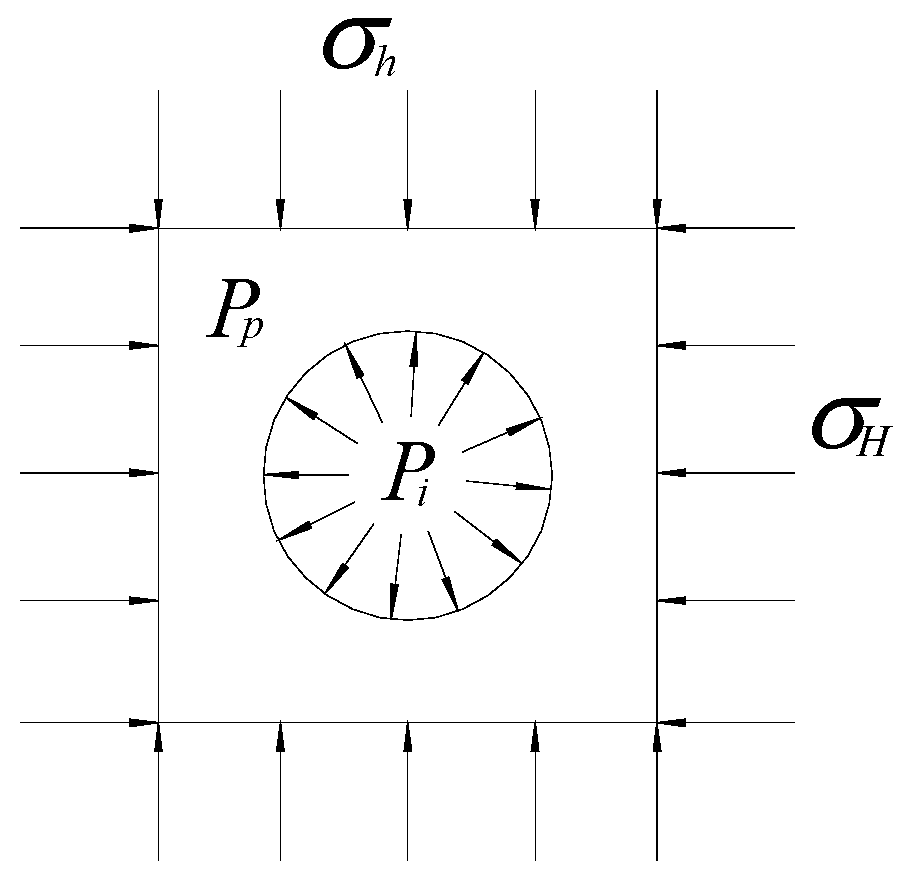
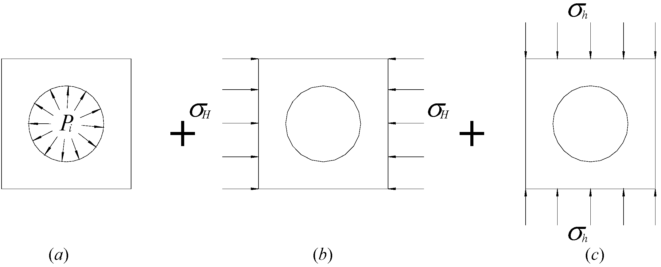
3.2. Determination of the Principal Stress at the Collapse of Shale Shaft Wall
3.3. Twin Shear Unified-Strength Solution of Critical Collapse of the Shale Shaft Wall
4. Discussion
5. Conclusions
Author Contributions
Funding
Institutional Review Board Statement
Informed Consent Statement
Data Availability Statement
Conflicts of Interest
References
- Shakib, J.T.; Ghaderi, A.; Shahri, A.A. Analysis of hydraulic fracturing length and aperture on the production rate in fractured reservoir. Life Sci. 2012, 9, 1769–1777. [Google Scholar]
- Zhao, W.C.; Liu, Y.; Wang, T.T.; Ranjith, P.G.; Zhang, Y.F. Stability analysis of wellbore for multiple weakness planes in shale formations. Geomech. Geophys. Geo-Energy Geo-Resour. 2021, 7, 44. [Google Scholar] [CrossRef]
- Li, G.R.; Shi, Y.H.; Xia, H.Q.; Han, L.F. A new method for mechanical analysis of borehole wall stability based on Mogi-Coulomb strength criterion. China Saf. Prod. Sci. Technol. 2018, 14, 70–75. [Google Scholar]
- Sun, H.R.; Liu, H.B.; Shuai, C.; Wang, J.J.; Xu, H. Study on plastic-brittleness mechanical properties and failure law of deep brittle shale under complex mechanical environment of wellbore. Earth Environ. Sci. 2021, 6, 062080. [Google Scholar] [CrossRef]
- Hao, J.L.; Qin, G.S.; Cai, Q.X. Experimental study on acoustic and elastic parameters of rocks samples in DongPu depression. J. Oil Gas Technol. 2012, 32, 57–61. [Google Scholar]
- Dou, T.W.; Liu, Q.Y.; Ren, H.T.; Sun, J.T.; Zhou, Y. Lateral distribution law of formation rock anti-rilling property. Acta Pet. Sin. 2016, 37, 144–149. [Google Scholar]
- Suranto, A.M.; Buntoro, A.; Prasetyadi, C.; Wibowo, R.A. Feasibility study on the application of dynamic elastic rock properties from well log for shale hydrocarbon development of brownshale formation in the bengkalis trough, central sumatra basin, indonesia. J. Geosci. Eng. Environ. Technol. 2021, 6, 81–85. [Google Scholar] [CrossRef]
- Sheng, Y.S.; Zhang, Y.G.; Gu, M.Y.; Liang, Y.H.; Shi, Y.M.; Fang, Y.Y.; Du, S.H. Static and dynamic mechanical parameter calibration of tight reservoir rock mass under in-situ condition. Oil Gas Geol. 2016, 37, 109–116. [Google Scholar]
- Tang, J. Experimental study of static and dynamic moduli for anisotropicrock. Chin. J. Rock Mech. Eng. 2014, 33, 3185–3191. [Google Scholar]
- Asef, M.R.; Farrokhrouz, M. A semi-empirical relation between static and dynamic elastic modulus. J. Pet. Sci. Eng. 2017, 157, 359–363. [Google Scholar] [CrossRef]
- Najibi, A.R.; Ghafoori, M.; Lashkaripour, G.R.; Asef, M.R. Empirical relations between strength and static and dynamic elastic properties of Asmari and Sarvak limestones, two main oil reservoirs in Iran. J. Pet. Sci. Eng. 2015, 126, 78–82. [Google Scholar] [CrossRef]
- Ghafoori, M.; Rastegarnia, A.; Lashkaripour, G.R. Estimation of static parameters based on dynamical and physical properties in limestone rocks. J. Afr. Earth Sci. 2018, 137, 22–31. [Google Scholar] [CrossRef]
- Ge, H.K.; Chen, Y.; Lin, Y.S. Microscopic mechanism of difference between static and dynamic elastic parameters of rock. J. Pet. China 2001, 25, 34–36. [Google Scholar]
- Fan, Z.Y.; Lin, C.Y.; Wang, T.X. Logging optimization modeling on brittleness index of tight formation rocks. Acta Pet. Sin. 2015, 36, 1411–1420. [Google Scholar]
- Yun, M.H.; Guan, Z.N. The estimation of P and S-wave velocities in sandstone under in-situ conditions. Geophys. Prospect. Pet. 2002, 41, 1289–1292. [Google Scholar]
- Lin, H.; Zhang, Y.; Cheng, Y.F.; Chen, L.; Zheng, Y.H.; Zhang, Z.H.; Fan, F.; Dong, H.D.; Tu, H.H. The static mechanics characteristics in Ningwu basin. Coal Geol. Explor. 2014, 42, 50–54. [Google Scholar]
- Bian, H.Y.; Wang, F.; Zhang, Y.H.; Yue, C.W. Experimental study of dynamic and static clastic parameters of tight sandstones under reservoir conditions. Chin. J. Rock Mech. Eng. 2015, 34, 3045–3054. [Google Scholar]
- Li, H.; Dong, C.; Yu, H.; Zhao, X.; Li, Y.; Cao, L.L.; Qu, M. Static and dynamic mechanical properties of organic-rich gas shale. Geofluids 2021, 2021, 6695975. [Google Scholar] [CrossRef]
- Xie, R.; Zhou, W.; Liu, C.; Yin, S.; Radwan, A.; Lei, W.; Cai, W. Experimental investigation on dynamic and static rock mechanical behavior, failure modes, and sequences of frequent interbedded sand and shale reservoirs. Interpretation 2022, 10, 23–36. [Google Scholar] [CrossRef]
- Han, T.; Yu, H.; Fu, L.Y. Correlations between the static and anisotropic dynamic elastic properties of lacustrine shales under triaxial stress: Examples from the Ordos Basin, China. Geophysics 2021, 86, 191–202. [Google Scholar] [CrossRef]
- Wu, S.C.; Zhang, M.; Zhang, S.H.; Jiang, R.H. Study on determination method of equivalent Mohr-Coulomb strength parameters of a modified Hoek-Brown failure criterion. Rock Soil Mech. 2019, 40, 4165–4177. [Google Scholar]
- Guo, J.Q.; Liu, X.R.; Huang, W.F.; Luo, X.; Niu, L. M-C strength criterion based on elastic strain energy. J. Tongji Univ. Nat. Sci. 2018, 46, 1168–1174. [Google Scholar]
- Comanici, A.M.; Barsanescu, P.D. Modification of Mohr’s criterion in order to consider the effect of the intermediate principal stress. Int. J. Plast. 2018, 108, 40–54. [Google Scholar] [CrossRef]
- Singh, A.; Rao, K.S.; Ayothiraman, R. Study on Mohr–Coulomb based three-dimensional strength criteria and its applition in the stability analysis of vertical borehole. Arab. J. Geosci. 2019, 12, 578. [Google Scholar] [CrossRef]
- Zhang, C.G.; Gao, B.X.; Li, T.B.; Shan, Y.P. An elastic-plastic solution for frost heaving force of cold region tunnels considering transversely isotropic frost heave and displacement release. Rock Soil Mech. 2021, 42, 2967–2976. [Google Scholar]
- Kwaśniewski, M.; Mogi, K. Effect of the intermediate principal stress on the failure of a foliated anisotropic rock. Mech. Jt. Faulted Rock 2020, 9, 407–416. [Google Scholar]
- Li, X.B.; Feng, F.; Li, D.Y.; Du, K.; Ranjith, P.G.; Rostami, J. Failure characteristics of granite influenced by sample height-to-width ratios and intermediate principal stress under true-triaxial unloading conditions. Rock Mech. Rock Eng. 2018, 51, 1321–1345. [Google Scholar] [CrossRef]
- You, W.; Dai, F.; Liu, Y.; Du, H.; Jiang, R.C. Investigation of the influence of intermediate principal stress on the dynamic responses of rocks subjected to true triaxial stress state. Int. J. Min. Sci. Technol. 2021, 31, 913–926. [Google Scholar] [CrossRef]
- Yu, M.H. Unified Strength Theory and Its Applications; Springer: Berlin/Heidelberg, Germany, 2004; pp. 37–69. [Google Scholar]
- Deng, L.; Fan, W.; Yu, M. Parametric study of a loess slope based on unified strength theory. Eng. Geol. 2018, 233, 98–110. [Google Scholar] [CrossRef]
- Rong, C.; Shi, Q. Axial-strength model for FRP-confined concrete based on the improved twin shear strength theory. Compos. Struct. 2018, 202, 102–110. [Google Scholar] [CrossRef]
- Zhao, C.; Wang, Y.B.; Zhao, C.; Wu, Y.; Fei, Y. Analysis of drained cavity unloading–contraction considering different degrees of intermediate principal stress with unified strength theory. Int. J. Geomech. 2020, 20, 04020086. [Google Scholar] [CrossRef]
- Cui, Y.; Qu, Z.; Zhao, J.H.; Wang, P. Research on crack tip plastic zone of type I cracks for shale. J. Chengdu Univ. Technol. Sci. Technol. Ed. 2019, 46, 704–710. [Google Scholar]
- Guan, S.Y.; Bai, Y.T. Stability analysis of tunnel structures based on the twin-shear unified strength theory with strain-softening effect. Eng. Mech. 2018, 35, 205–211. [Google Scholar]
- Jiang, Z.L.; Zhao, J.H.; LÜ, M.T.; Zhang, L. Unified solution of limit interminal pressure for double-layered thick-walled cylinder based on bilinear hardening model. Eng. Mech. 2018, 35, 6–12. [Google Scholar]
- Yu, M.; Lin, C.M.; Yin, R.P. Analysis of loosen zone of surrounding rock based on improved twin shear unified strength criterion. Chin. J. Undergr. Space Eng. 2018, 14, 379–386. [Google Scholar]
- China National Standardization Administration. Method for Determination of Physical and Mechanical Properties of Coal and Rock (GB/T 23561.8-2009); China Standards Press: Beijing, China, 2009. [Google Scholar]
- China National Standardization Administration. Test Rules for Physical and Mechanical Properties of Rock (DZ/T 0276.24-2015); China Standards Press: Beijing, China, 2015. [Google Scholar]
- Asheghi, R.; Hosseini, S.A.; Saneie, M.; Shahri, A.A. Updating the neural network sediment load models using different sensitivity analysis methods: A regional application. J. Hydroinform. 2020, 22, 562–577. [Google Scholar] [CrossRef] [Green Version]
- Saltelli, A. Sensitivity analysis for importance assessment. Risk Anal. 2020, 22, 579–590. [Google Scholar] [CrossRef]
- Christopher, F.H.; Patil, S.R. Identification and review of sensitivity analysis methods. Risk Anal. 2002, 22, 553–578. [Google Scholar] [CrossRef]
- Xiong, L.K.; Wang, S.; Xu, F.L.; Zhu, H.L.; Chen, Q. Dynamic and static elastic modulus conversion for shale in the Jiaoshiba Block, Fuling area. Pet. Dilling Tech. 2016, 44, 40–44. [Google Scholar]
- Li, K.; Ran, C.; Shao, M.J. Study on rock mechanics and dynamic-static parameter transformation models in the second member of Xujiahe formation in west Sichuan Basin. Sci. Eng. 2016, 16, 17–22. [Google Scholar]
- Abbaszadeh Shahri, A.; Shan, C.L.; Larsson, S. A novel approach to uncertainty quantification in groundwater table modeling by automated predictive deep learning. Nat. Resour. Res. 2022, 31, 1351–1373. [Google Scholar] [CrossRef]
- Chen, H.C.; Wu, P.C.; Huang, J.Y.; Chen, L.A. Uncertainty analysis for measurement of measurand. Measurement 2010, 43, 1250–1254. [Google Scholar] [CrossRef]
- Villarraga-Gómez, H.; Thousand, J.D.; Smith, S.T. Empirical approaches to uncertainty analysis of X-ray computed tomography measurements: A review with examples. Precis. Eng. 2020, 64, 249–268. [Google Scholar] [CrossRef]
- Moffat, R.J. Using uncertainty analysis in the planning of an experiment. Fluid Eng. 1985, 107, 173–178. [Google Scholar] [CrossRef]
- Feng, R. Uncertainty analysis in well log classification by Bayesian long short-term memory networks. J. Pet. Sci. Eng. 2021, 205, 108816. [Google Scholar] [CrossRef]
- Deng, J.G.; Cheng, Y.F.; Chen, M.; Wei, B.H. Borehole Stability Prediction Technology; Petroleum Industry Press: Beijing, China, 2008; pp. 160–161. [Google Scholar]

| The Serial Number | The Lithology | The Specimen Number | Grain Density (g/cm3) | Porosity (%) | Permeability (10−3 μm2) | Rock Density (g/cm3) |
|---|---|---|---|---|---|---|
| 1 | Gray-black calcareous shale | #5 | 2.75 | 2.8 | 0.149 | 2.67 |
| 2 | #9 | 2.75 | 2.9 | 0.022 | 2.67 | |
| 3 | #76 | 2.71 | 0.6 | 0.010 | 2.69 |
| Parameter | Confining Pressure Increase | Temperature Increase | Buried Depth Increase | |
|---|---|---|---|---|
| Category | ||||
| Dynamic elastic modulus | Increase | Decrease | Not clear | |
| Static elastic modulus | Increase, especially faster at high temperature | Increase, especially faster at high pressure | Increase | |
| Coefficients | a | c | R | |
|---|---|---|---|---|
| Temperature | ||||
| 25 °C | 1.010 | −26.163 | 0.9814 | |
| 50 ° | 2.174 | −87.452 | 0.9940 | |
| 70 °C | 2.474 | −100.75 | 0.9928 | |
| 90 °C | 2.721 | −111.12 | 0.9961 | |
| 110 °C | 3.029 | −124.09 | 0.9981 | |
| Well Depth/m | 600 | 1800 | 3000 | Intermediate Principal Stress Effect Comparison | |||
|---|---|---|---|---|---|---|---|
| b Value | 600 m | 1800 m | 3000 m | ||||
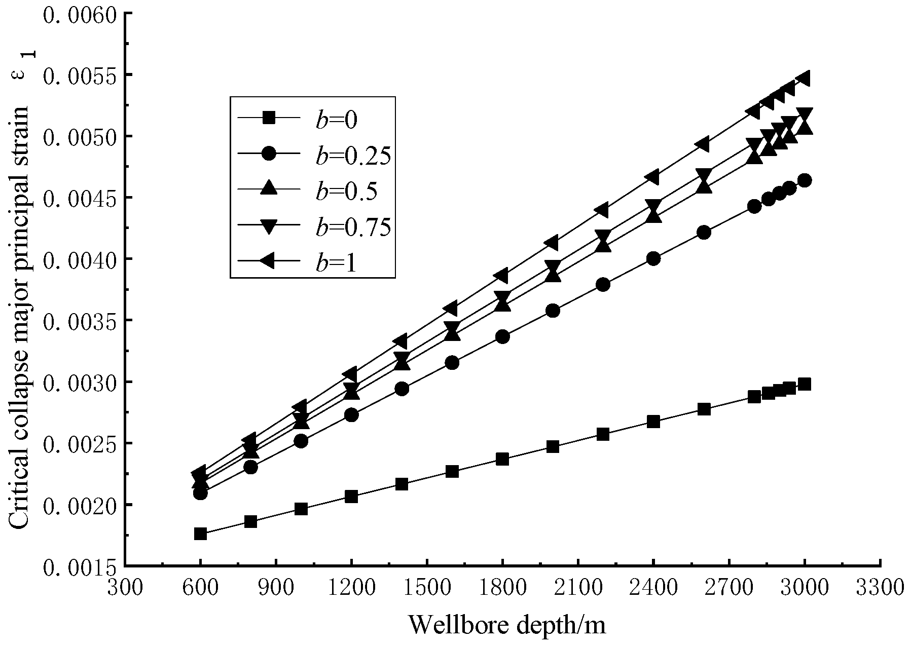
| 0 | 0.00176 | 0.00237 | 0.00298 | 22.1% | 38.8% | 45.5% | |
| 0.25 | 0.00209 | 0.00337 | 0.00464 | ||||
| 0.5 | 0.00218 | 0.00361 | 0.00505 | ||||
| 0.75 | 0.00220 | 0.00370 | 0.00519 | ||||
| 1 | 0.00226 | 0.00387 | 0.00547 | ||||
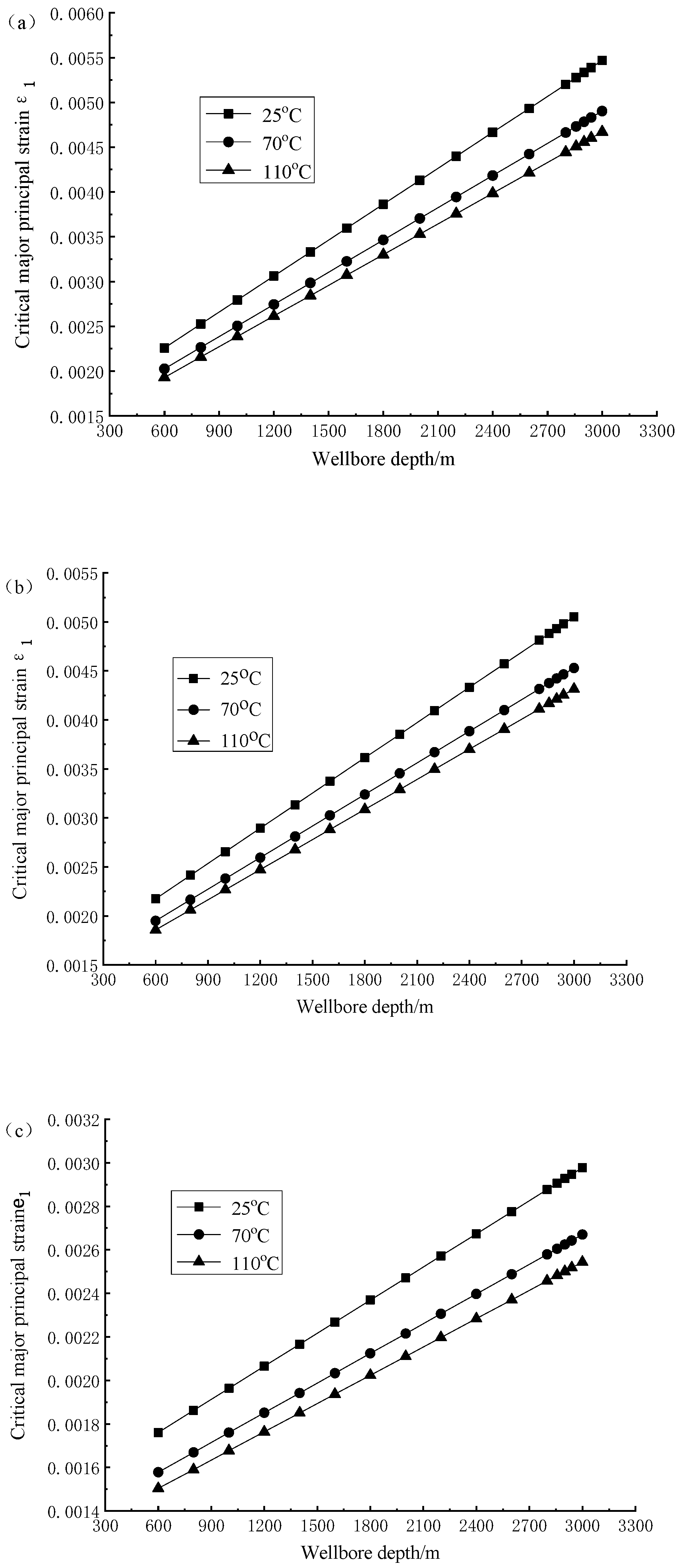
| Conditions | 25 °C | 70°C | 110°C | |||||||
| bValue | 600 m | 1800 m | 3000 m | 600 m | 1800 m | 3000 m | 600 m | 1800 m | 3000 m | |
| 0 | 0.00176 | 0.00237 | 0.00298 | 0.00158 | 0.00212 | 0.00267 | 0.00150 | 0.00202 | 0.00254 | |
| 0.5 | 0.00218 | 0.00361 | 0.00505 | 0.00195 | 0.00324 | 0.00453 | 0.00186 | 0.00309 | 0.00432 | |
| 1 | 0.00226 | 0.00386 | 0.00547 | 0.00203 | 0.00346 | 0.00490 | 0.00193 | 0.00330 | 0.00467 | |
| Conditions | Intermediate principal stress effect comparison | |||||||||
| bValue | 25°C | 70°C | 110°C | |||||||
| 0–1 | 22.1–45.5% | 22.2–45.5% | 22.3–45.6% | |||||||
Publisher’s Note: MDPI stays neutral with regard to jurisdictional claims in published maps and institutional affiliations. |
© 2022 by the authors. Licensee MDPI, Basel, Switzerland. This article is an open access article distributed under the terms and conditions of the Creative Commons Attribution (CC BY) license (https://creativecommons.org/licenses/by/4.0/).
Share and Cite
Cui, Y.; Qu, Z.; Wang, L.; Wang, P.; Fang, J. Twin Shear Unified Strength Solution of Shale Gas Reservoir Collapse Deformation in the Process of Shale Gas Exploitation. Energies 2022, 15, 4691. https://doi.org/10.3390/en15134691
Cui Y, Qu Z, Wang L, Wang P, Fang J. Twin Shear Unified Strength Solution of Shale Gas Reservoir Collapse Deformation in the Process of Shale Gas Exploitation. Energies. 2022; 15(13):4691. https://doi.org/10.3390/en15134691
Chicago/Turabian StyleCui, Ying, Zhan Qu, Liang Wang, Ping Wang, and Jun Fang. 2022. "Twin Shear Unified Strength Solution of Shale Gas Reservoir Collapse Deformation in the Process of Shale Gas Exploitation" Energies 15, no. 13: 4691. https://doi.org/10.3390/en15134691