Article

A Novel VSG Control Strategy for UPS Voltage Source Inverter with Impulsive Load

1
School of Electrical and Control Engineering, Henan University of Urban Construction, Pingdingshan 467036, China
2
College of Electrical Engineering & New Energy, China Three Gorges University, Yichang 443002, China
*
Author to whom correspondence should be addressed.
Energies 2022, 15(13), 4702; https://doi.org/10.3390/en15134702
Submission received: 29 May 2022 / Revised: 23 June 2022 / Accepted: 24 June 2022 / Published: 27 June 2022
(This article belongs to the Special Issue Advanced Grid Integration with Power Electronics)

Abstract

:
This paper proposes a novel control strategy to alleviate the impulsive current for Uninterruptible Power Supply (UPS), which is designed based on the theory of virtual synchronous generator (VSG) and dynamic switching method. The power quality of UPS will become distortion when the instantaneous impulsive load is imposed on UPS. Especially, the output current of UPS will increase quickly in short time. In order to maintain the uninterrupted output voltage and reduce the distortion of output voltage of UPS under the action of instantaneous impulse load, Dynamic switching method is proposed to resist impulse load with large scale impulse current, Meanwhile, the VSG control strategy is adopted to deal with the slow power switching and provide virtual inertia for the system, so that the output voltage of UPS can remain uninterrupted and stable. Finally, simulation and experimental results show that this method can effectively suppress the impulse current, reduce the output voltage distortion of UPS inverter, and ensure the good performance of On-line UPS under impulse load.

1. Introduction

Uninterruptible power supply (UPS), as an energy storage power supply, is widely used in medical, communication and industrial fields [1,2,3]. When the municipal power failure occurs, UPS immediately switches the working state, which can still ensure the sustainable operation of electronic equipment. According to the structure characteristics of UPS [4,5], it can be divided into dual conversion online UPS, backup UPS, online interactive UPS. Online UPS is composed of rectifier module and inverter module, which is widely used in high-power electrical equipment. When the municipal power is normal, the municipal power provides AC required by the load after the rectifier module and inverter module. When the power grid fails, the UPS battery pack provides the DC-side voltage to the inverter to realize the power supply of the inverter to the load; if the UPS system needs to repair, switch to the bypass mode automatically to power the load directly to realize UPS system uninterruptedly power supply to the load.
During the period of UPS operation of the nonlinear impulsive load, the output load current can reach 5–7 times of rated current. In fact, the maximum load current that the UPS inverter can bear is only three times the rated load current [6], so excessive output current can cause the UPS to run abnormally or even damaged. In this situation, UPS will automatically switch to the bypass mode to power the load through AC grid directly or supply power to the load through current conversion of battery and inverter.
In order to improve the over-current generated by UPS inverter with impulsive load, in recent years, there have been many studies on UPS in terms of anti-impulsive current. There are two main methods: hardware blocking current limiting method [7] and instantaneous current limiting method [8]. The hardware blocking current limiting method is that the driving pulse is at a low level when the UPS output current is greater than the set value. When the output current returns to normal, the driving pulse returns to normal. The instantaneous current limiting method forces the current reference value to be lowered or all pulses closed when the pulse current appears. However, these two methods will both cause distortion or interruption of output voltage and current.
The inverter control strategy based on virtual synchronous generator technology can fully simulate the operation characteristics of synchronous generator and has made great progress in many fields. In reference [9], the voltage and angular frequency of the distributed generators units (DGs) based on the traditional VSG control strategy are easily affected by the power fluctuations and high-frequency noises, and the adjustment of the power is also easily affected by the coupling of the DGs. An improved VSG control strategy combing coupling compensation, improved torque governor and excitation control is proposed. In reference [10], the wind farm is equivalent to a virtual synchronous generator (VSG) by configuring energy storage battery on the AC side of the wind farm, and then proposes a virtual synchronous machine control technology for energy storage system to realize the power balance of the regulation system, which can not only maintain the voltage stability of the power grid, but also realize the parallel expansion of multiple machines. Reference [11] aims at the problem of small capacity and low voltage level of the traditional battery energy storage system (BESS), a single-stage cascaded H-bridge with energy spring (ES) which can eliminate the secondary pulsating current injecting into the battery. In addition, the virtual synchronous generator (VSG) control strategy is adopted for the grid-friendly integration of the BESS. Reference [12] presents a method of charge of electric vehicles based on synchronous inverter, which realizes the adaptive adjustment of active power and reactive power input and output of charging station and improves the stability and reliability of power grid. Reference [13] focuses on the research of virtual synchronous generator technology and its application in marine micro-grid, then physical and mathematical models of inertia and damping parameters are given, and their setting methods are discussed.
At present, there are few references on the combination of VSG control strategy and UPS with impulsive load. In order to improve the operation characteristics of UPS under impulse load, the contributions of this paper are as follows: the VSG control strategy is applied to UPS voltage source inverter to provide virtual inertia for UPS system; Combined with a method of dynamic switching sequence of UPS, the power supply is quickly switched when the pulse load is connected to UPS to protect the UPS inverter from damaged. The operation status of UPS with impulsive load is described and analyzed in detail. Finally, the simulation and experimental results verify the effectiveness of the proposed strategy to ensure the good operation of UPS.

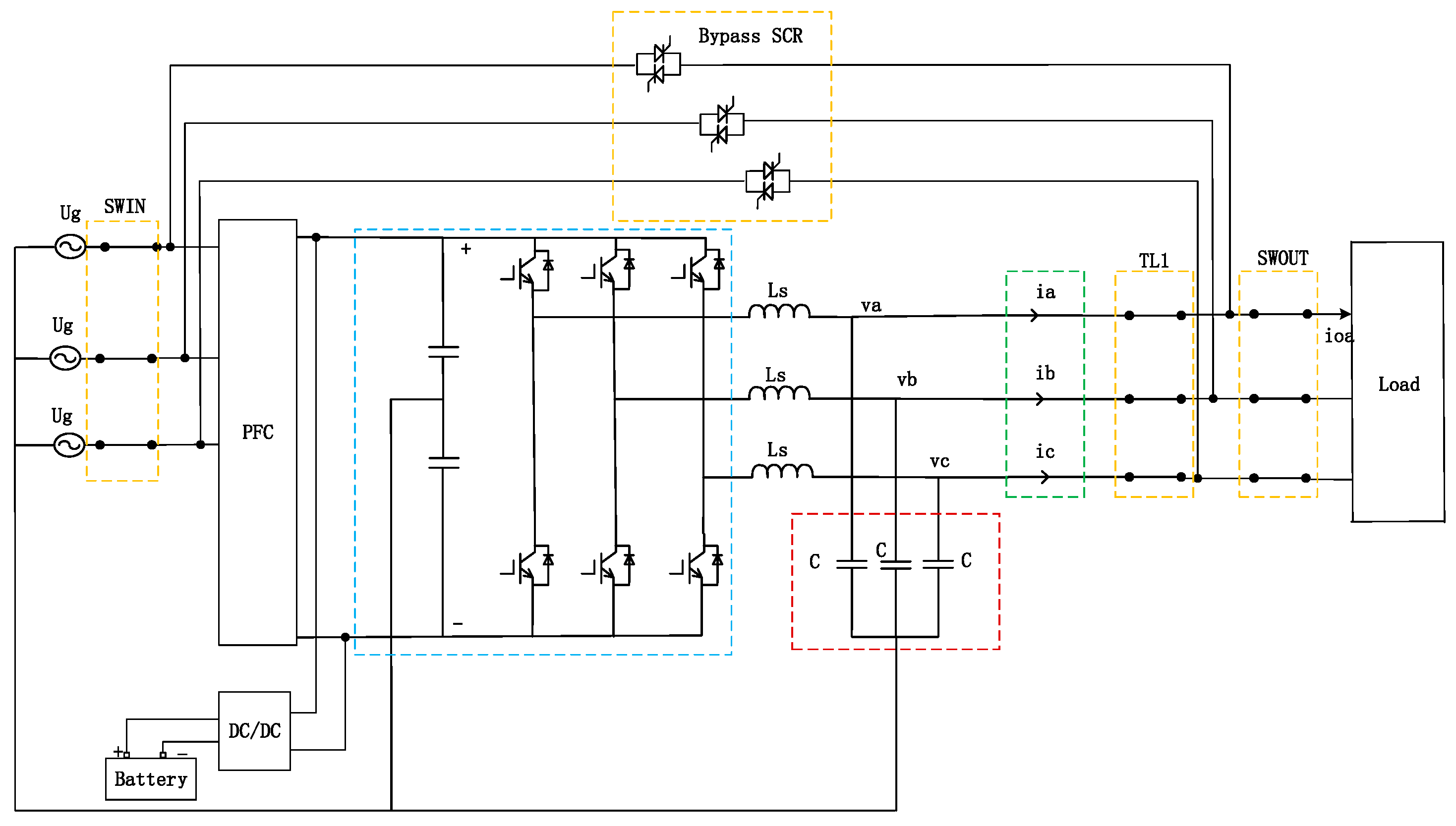
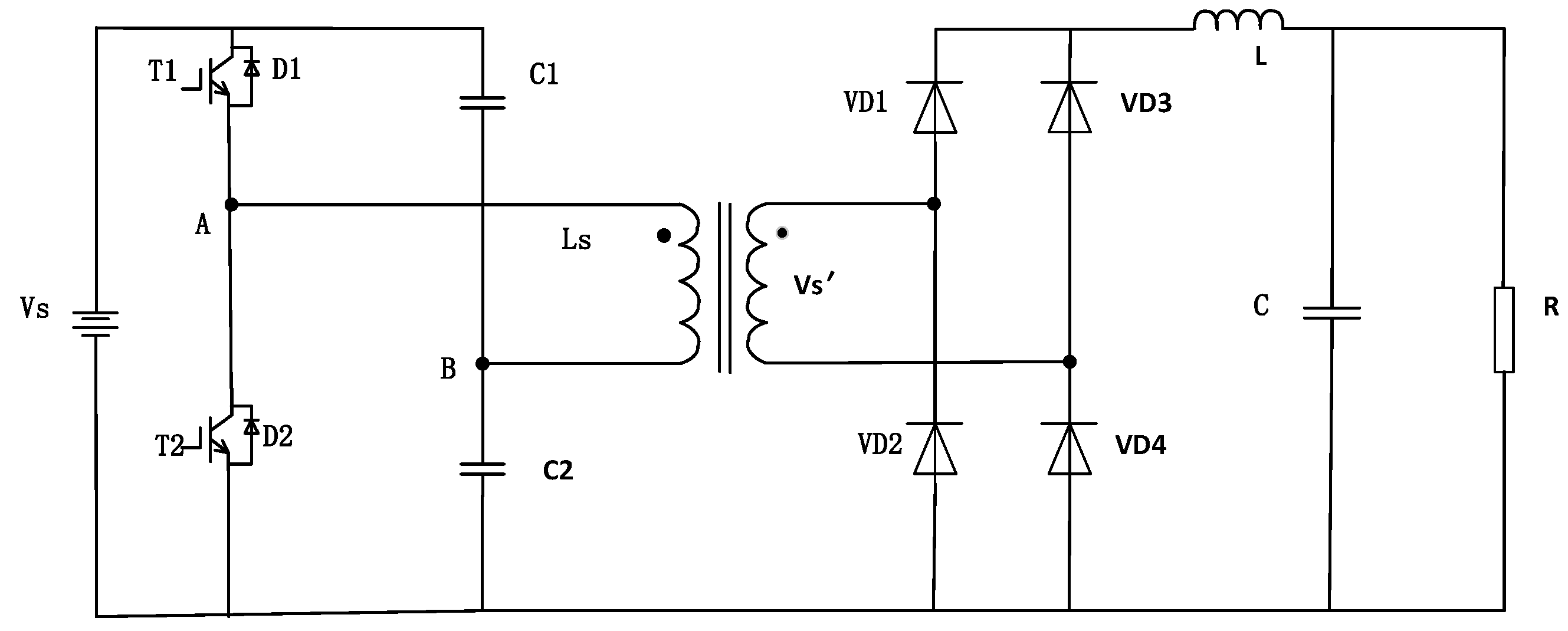
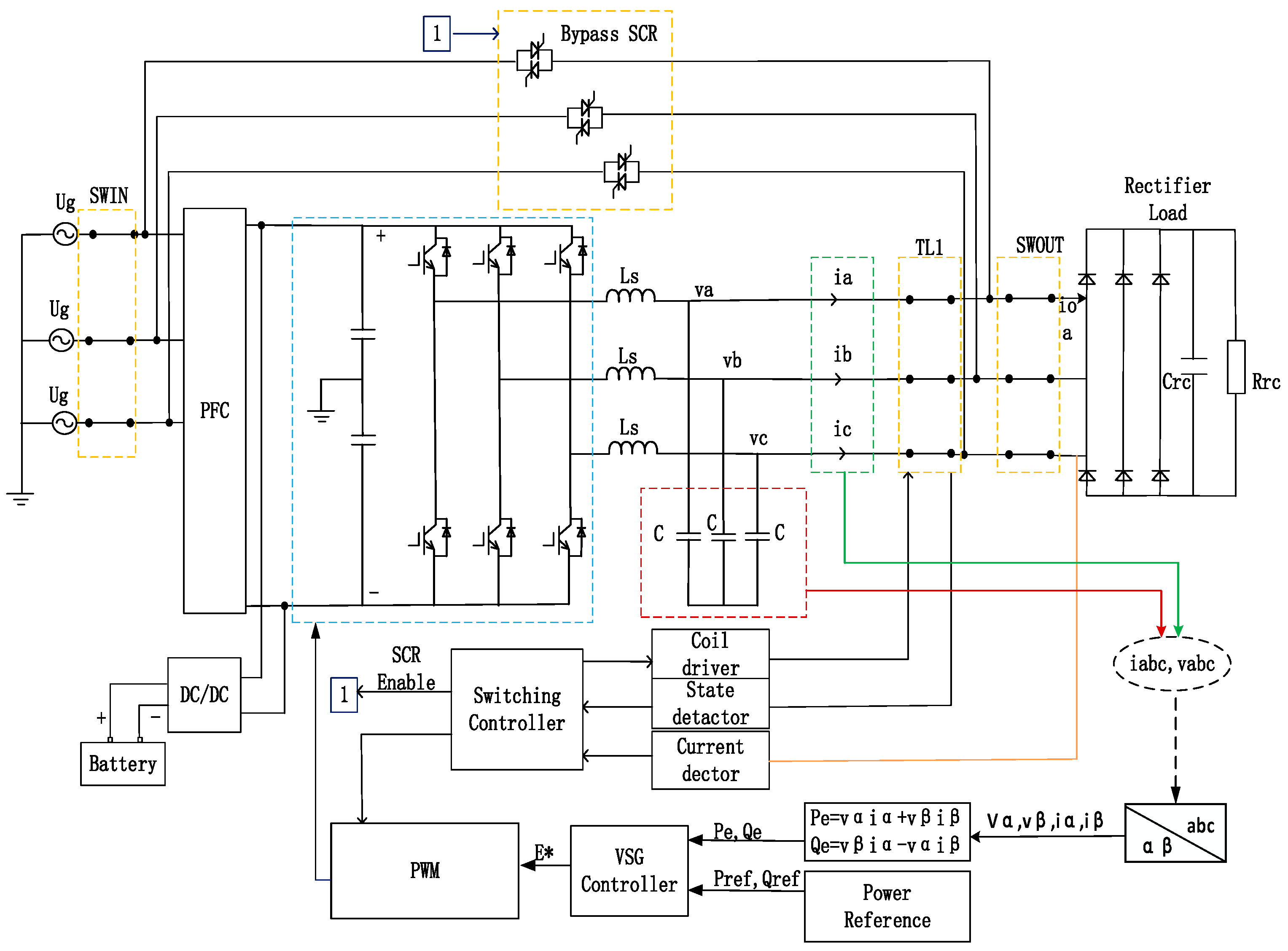
2. System Topology Analysis and Design

The topology of on-line UPS is shown in Figure 1.
It can be seen from Figure 1, UPS includes power factor correction (PFC) circuit, by directional DC/DC, energy storage part, inverter, contactor TL1, switch SWIN, switch SWOUT, and bypass silicon-controlled rectifier (SCR). Three-phase four wire half bridge topology is adopted in UPS, which can realize independent control between each phase.
When UPS works normally, AC power provided by grid can be converted into DC power by PFC. Then the DC power is converted into AC power output on the one hand, on the other hand, the DC power is converted by directional DC/DC that charge the battery which be regarded as energy storage device. When grid fails, the energy storage device can be used as the power source of the load. The On-line UPS uses the battery to provide energy for the inverter, and then the inverter continues to provide high-quality sine wave AC for the load. The battery voltage is converted to a higher DC voltage by a DC/DC converter for use by the inverter.
In this paper, half bridge DC/DC converter with isolation function is selected. Figure 2 shows the design process of DC side voltage control system. Half bridge DC/DC converter is composed of half bridge inverter, high frequency transformer and output rectifier filter circuit. The power transistor T1 and T2 form one bridge arm, and the two equal capacitors C1 and C2 form the other bridge arm. The midpoint AB of the two bridge arms is an indirect high-frequency transformer. Since the capacitors C1 and C2 are large, the potential at point B remains unchanged and is equal to 1/2   U s . The working principle of half bridge DC/DC converter is as follows. When T1 is on, the voltage on the primary coil of the transformer is 1/2   U s . The “•” end of the winding induced electromotive force is of “positive” polarity, and the “•” end of the secondary winding is also of “positive” polarity. Therefore, the diodes VD1 and VD4 are turned on, and the output filter inductance current increases; When T1 is turned off, the inductive current cannot change abruptly, so the induced electromotive force on the primary coil of the transformer prevents the current from decreasing. The voltage polarity between AB is reversed, and the point A is “negative” and the point B is “positive”. The induced electromotive force passes through the capacitor C2 and the freewheeling diode D2 until the energy loss is completed, and the current becomes zero. Then T2 turns on, and its working principle is the same as that of T1.
UPS usually provides power to different loads, such as motor, rectifier device. When the impulsive load is imposed on UPS, it will inevitably affect the output current and voltage of UPS, and even damage the hardware of UPS. To achieve better performance of UPS, it is essential to discuss the control method of UPS with instantaneous impulsive load.

3. The Proposed Control Strategy

In this section, the basic concept of VSG is illustrated firstly, then the VSG control strategy and dynamic switching method are presented.

3.1. VSG Control Strategy
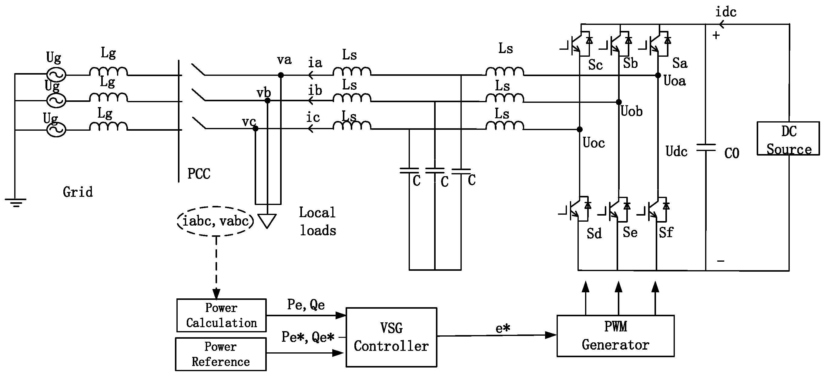
3.1.1. VSG Topology

In Figure 3, e a b c = [ e a   e b   e c ] T , u a b c = [ u a   u b   u c ] T , i a b c = [ i a   i b   i c ] T , P e , Q e are electromotive force, output voltage, output current, active power and reactive power of VSG, respectively. Rs and Ls are virtual resistance and virtual inductance, respectively. VSG is a converter that has the similar internal mechanism and external characteristics of the traditional synchronous generator. According to the requirements, the energy storage system can be configured on its DC bus side to provide inertia. VSG takes the mathematical model of traditional synchronous generator as its one, so it has the dynamic characteristic and synchronization mechanism of traditional synchronous generator. VSG automatically regulates the active and reactive power when voltage and frequency change, so as to participate in the regulation of grid voltage and frequency. VSG can also provide inertia and damping to the system and improve the stability of grid. Furthermore, the converter can also operate as synchronous rectifier [14,15].
In UPS system, the energy storage system on DC bus side can provide inertia support for UPS system when VSG control strategy is adopted. By VSG method, the voltage and frequency will not change abruptly, and stability of UPS will be improved. Moreover, it can improve the disturbance rejection performance of UPS, especially for UPS with impulsive load.

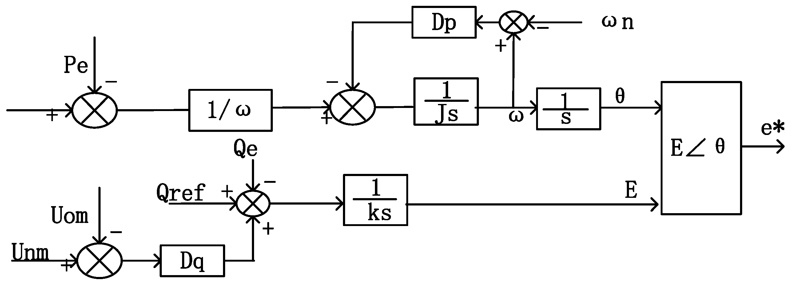
3.1.2. VSG Control Scheme

System modeling is to build the mathematical model of VSG according to traditional synchronous generator model with different orders. Different functions of VSG can be realized by mimicking traditional synchronous generators with different orders. At present, the second-order mathematical model of synchronous generator is mainly studied, including electromagnetic part and mechanical part.
According to the relationship between voltage and current on stator, electrical equation of synchronous generator can be obtained as follows:
U abc = R s i a b c L s d i a b c d t + e a b c
where U abc , i abc , L s , R s and e abc are stator voltage, stator current, stator inductance, stator resistance and electromotive force. The equation above reflects the external characteristics of generator, however, the electromagnetic relationship between the stator and the rotor can’t be represented. Considering the electromagnetic relationship between stator and rotor into consideration, electromotive force can be represented as follows [16]:
e a b c = M f i f θ 1 A + M f d i f d t B
where M f , i f , and θ 1   are mutual inductance, excitation current and rotor position, respectively. Vector A and B are defined as:
A = [ sin θ 1 sin ( θ 1 2 π 3 ) sin ( θ 1 + 2 π 3 ) ] , B = [ cos θ 1 cos ( θ 1 2 π 3 ) cos ( θ 1 + 2 π 3 ) ]
The mechanical equation of VSG is also called swing equation, which is mainly based on the rotor motion equation of generator. The rotor swing equation is obtained as [17]:
J θ = P m ω n P e ω n D p ( ω ω n )
where J, θ , P m , P e , D p , ω and ω n   are inertia constant, the generated rotation angle reference of inverter output voltage, reference value of active power produced by the governor, calculated active power, damping factor rotor angular frequency and nominal angular frequency, respectively.
The Q-V control method of VSG is to mimic the excitation regulation function of synchronous generator and realize the droop characteristic of reactive power and voltage amplitude. The Q-V control method mainly regulates the output voltage according to the voltage deviation value and the reactive power deviation value, and uses the voltage coefficient K to present the voltage regulation ability of VSG [18,19,20]. The droop mechanism of VSG can be written as:
K d E d t = Q r e f Q e + D q ( U n m U o m )
where Q r e f , Q e , U n m , U o m , D q , E, and K are given reactive power, calculated reactive power, reference voltage, amplitude of output voltage, droop coefficient, magnitude, reference voltage of VSG and integral coefficient. Then, the reference voltage e * could be written as E θ .
Based on the mathematical model established above, the schematic diagram of VSG can be presented as follows:
In Figure 4, VSG includes active power controller and reactive power controller. There are two reference signals P m , Q s e t , U n m   and   ω n need to be set before system operation. U o is measured signal. While P e , Q e are signal that calculated.
According to the current research results in [21,22], the calculation formula of active power P e and reactive power Q e   in VSG control system can be written as:
P e = v α i α + v β i β Q e = v β i α v α i β
where v α and v β , i α and i β are output voltage, output current of VSG in αβ frame.
Based on above analysis and VSG controller design, we can obtain the overall schematic of UPS with VSG strategy (See upper part of the next page for details). The schematic diagram of UPS includes power stage and VSG controller. Firstly, the output voltage and current of UPS are accumulated and converted to the corresponding signals in αβ frame by clark transformation, and the voltage and current signals in αβ frame are used to calculate the active power P e and reactive power Q e ; Then, the reference signal and its value which is calculated in last stage, are used to generate the angle and amplitude   E m of modulation signal by controller. Finally, the driving signals are gotten by pulse width modulator which are used to control the IGBT modules of inverter.

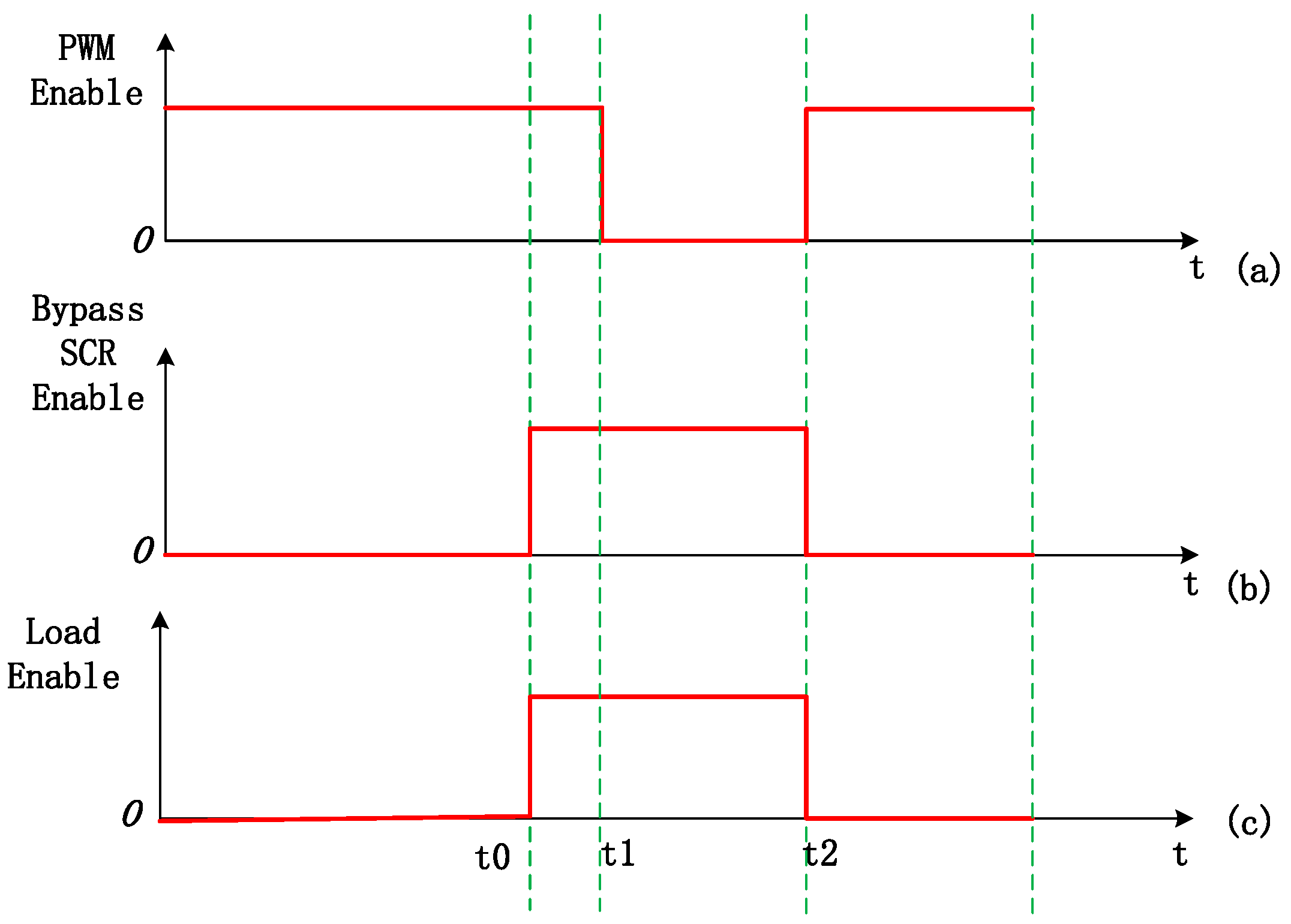
3.2. Dynamic Switching Method

When UPS is imposed on impulsive load, the output current will reach 5–7 times of the rated value. In order to effectively suppress the impact of instantaneous current, improve the stability of the output voltage and current, and protect the hardware of UPS, this paper proposes a dynamic switching method applied to UPS with impulsive load [23]. The switching sequence is shown in Figure 5.
Figure 5 shows the enable signal of PWM, Bypass SCR and the impulsive load. The high logic level indicates that they are on working, and the low logic level indicates that they are in locked state. The above figure shows the dynamic switching sequence of UPS inverter with pulse load. Assuming the UPS inverter operates under inverter mode till t 0 time. At t 0   time, the pulse load is connected to UPS, and the load enable is at high level. At the same time, the bypass SCR is also input, and the SCR enable is also at high level. During   t 0 to t 1 , UPS inverter supplies power to the load by the joint action of inverter and bypass SCR to resist large impulsive current; The PWM signal is disconnected at t 1   time, and during the period t 1 to t 2 , only the bypass SCR works, and the inverter does not work. After t 2 , the UPS inverter returns to the normal operation mode. The time period   t 0 to t 2 is the whole process of impulsive load switching.
The overall schematic diagram of UPS with proposed control scheme is shown in Figure 6.
Figure 6 presents the power stage of UPS, the dynamic switching controller and the VSG controller. The proposed control method in this paper includes dynamic switching control method and VSG control scheme. UPS is equipped with energy storage system, such as the battery in the figure above. Energy storage device can provide inertia for VSG system. The proposed strategy can effectively improve the performance of UPS with impulsive load.

4. The Simulation and Experimental Results

The simulation runs on the MATLAB/Simulink platform and adopts the typical equivalent system topology shown in Figure 6. The experiments results are verified by hardware in the loop experimental platform. The DC link voltage in the power converter is maintained at 1000 V by the front-end PFC, and the switching frequency of the converter is 10 kHz. The following are the design results of each parameter.

4.1. Simulation Parameters and Results

4.1.1. Simulation Parameters

Table 1 shows the simulation parameters of the main circuit of the system, select rated voltage, rated frequency, filter capacitor, inverter side inductance, switching frequency and load side inductance, respectively, are 220 V, 50 Hz, 80 × 10 6 F, 9 × 10 3   H and 10 kHz.
Table 2 shows the simulation parameters of the VSG, the controller parameters D p   , D q , J and K, respectively, are 5.1, 3.22, 0.04 and 0.001.

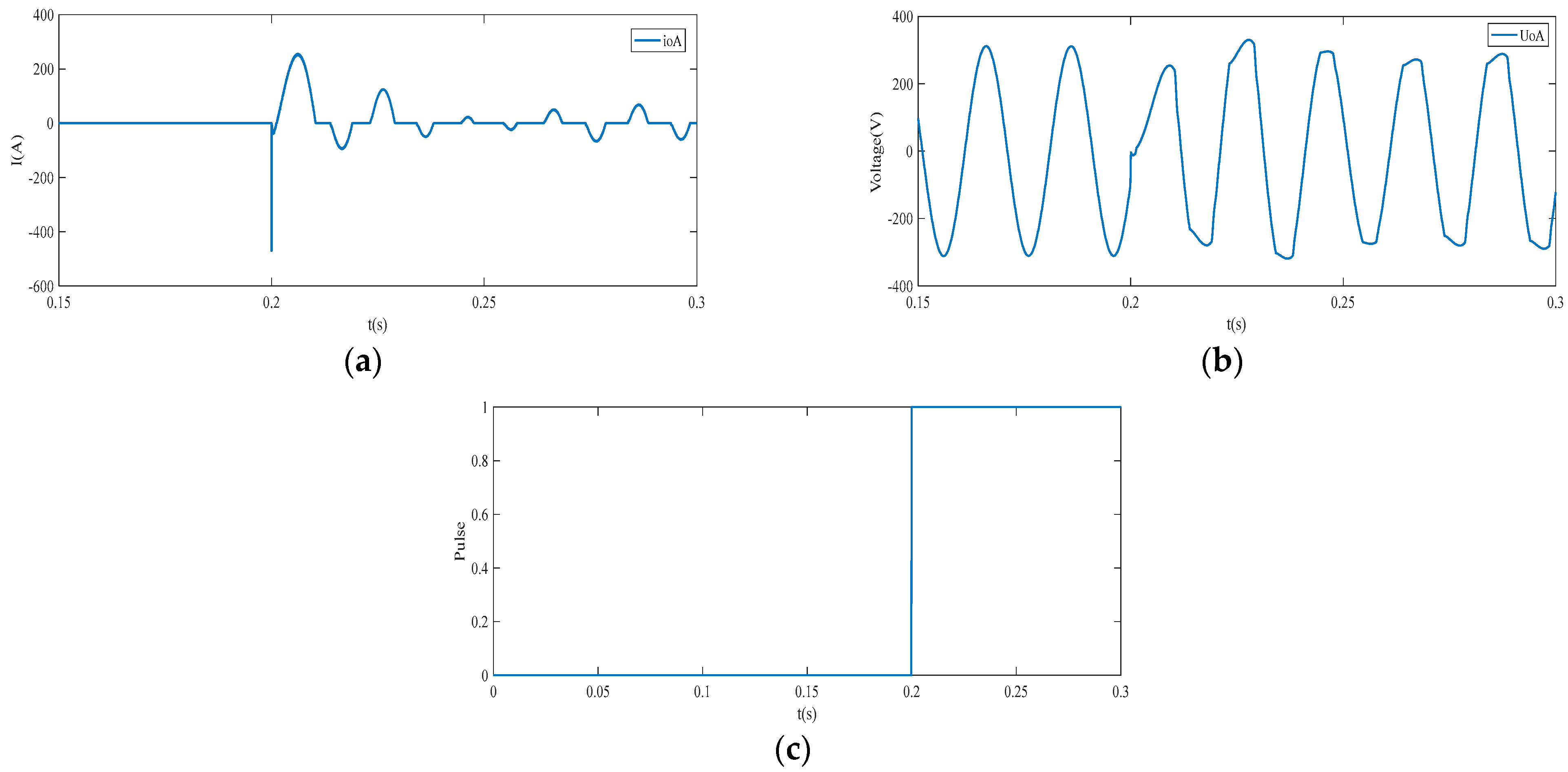
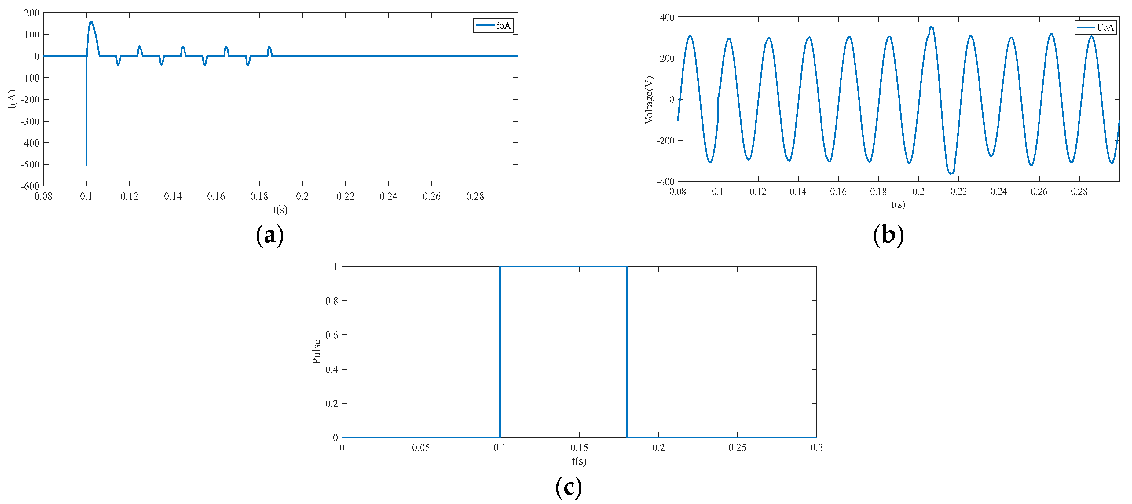
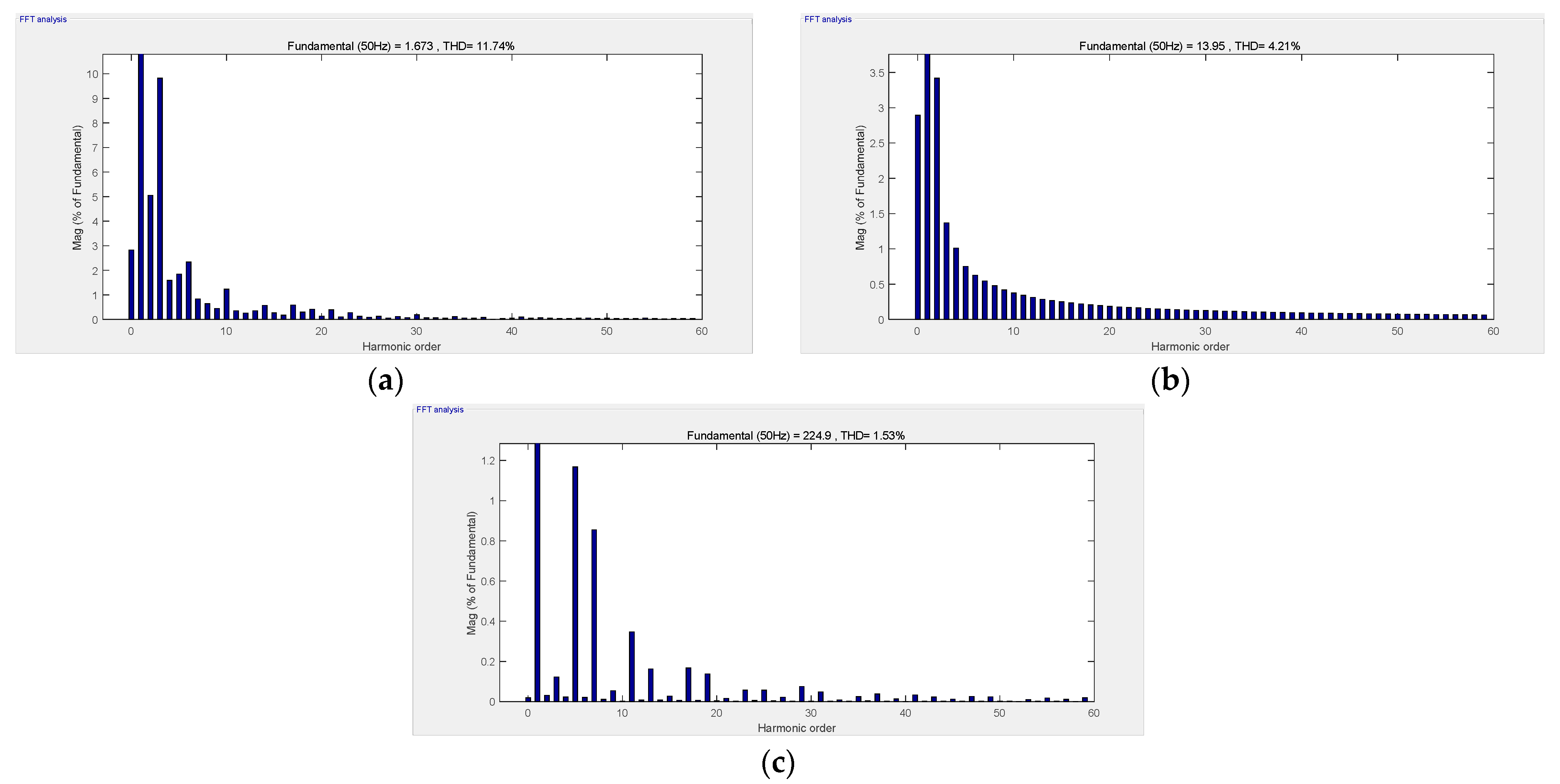
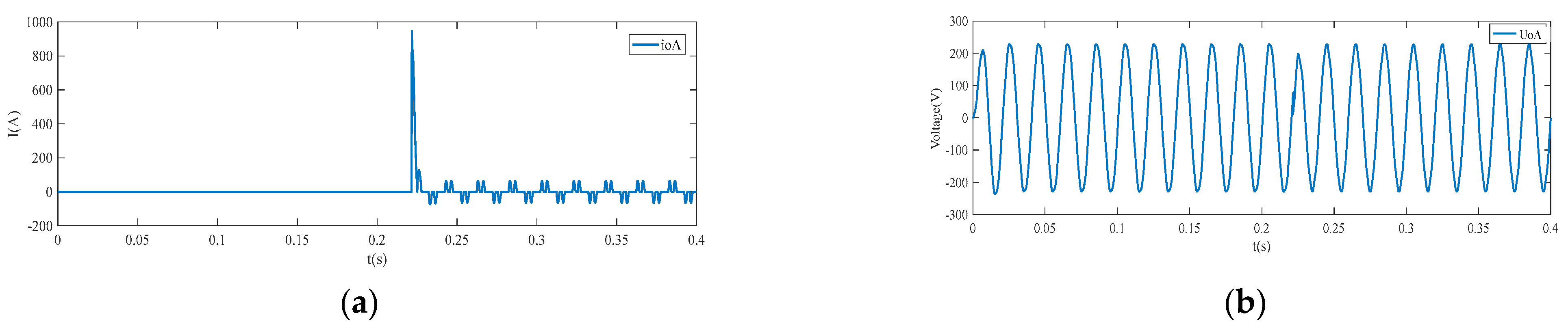
4.1.2. Simulation Results

In Figure 7a–c: output current of phase A i o A , output voltage of phase A U o A , pulse of load switch. At the time point t = 0.2 s, the UPS is imposed on rectifier load instantaneously: C r c = 2200 µF, R r c = 16 Ω. It can be seen that the current output is large and distorted, and the voltage is almost interrupted. This simulation results can be explained by current-limiting method: current-limiting method forces the driving pulses to be low when the impulsive current occurs and makes the driving pulses to be normal again after impulsive current.
In Figure 8a–c: output current of phase A i o A , output voltage of phase A U o A , pulse of load switch, at the time point t = 0.1 s, the UPS is imposed on instantaneous rectifier. Figure 8 shows that when UPS is applied to the instantaneous rectifier load, the output current decreases significantly and is relatively smooth; the output voltage waveform is obviously improved, which proves the effectiveness of the dynamic switching method.
Figure 9 shows the simulation results of UPS using VSG control strategy combined with dynamic switch method. The output of phase A of UPS inverter is selected as the analysis object. Figure 9a,b, load current of phase A i o A , load voltage of phase A U o A , At the time point t = 222 ms, the UPS is imposed on instantaneous rectifier load: C r c = 2200 µF, R r c = 16 Ω. It can be seen that the dynamic switching method will work immediately when the impulse current occurs. The output voltage of UPS could maintain uninterrupted, and the waveform is smooth.
In Figure 10a–c, THD of output voltage of UPS with current limiting method, dynamic switching method and VSG control strategy combined with dynamic switching method. The THD of UPS output voltage with current limiting method is 11.74%, the THD of UPS output voltage with separate dynamic switching method is 4.21%, while the THD of UPS output voltage with VSG control strategy combined with dynamic switching method is only1.53%, This simulation results can be explained by control method: good steady state of UPS can be achieved by VSG control strategy.
Compare with Figure 9, Figure 11 and Figure 12 present the simulation results of UPS with rectifier load in case of different capacitances, and other parameter settings are the same as those in Figure 9. In Figure 11, at the time point t = 222 ms, the UPS is imposed on instantaneous rectifier load, C r c = 5500 µF, R r c = 16 Ω. In Figure 12, at the time point t = 222 ms, the UPS is imposed on instantaneous rectifier load, C r c = 9900 µF, R r c = 16 Ω. It is obvious that when the pulse type load is input, the current waveform does not change significantly with the increase of load, while the smoothness of voltage waveform gradually decreases with the increase of load.

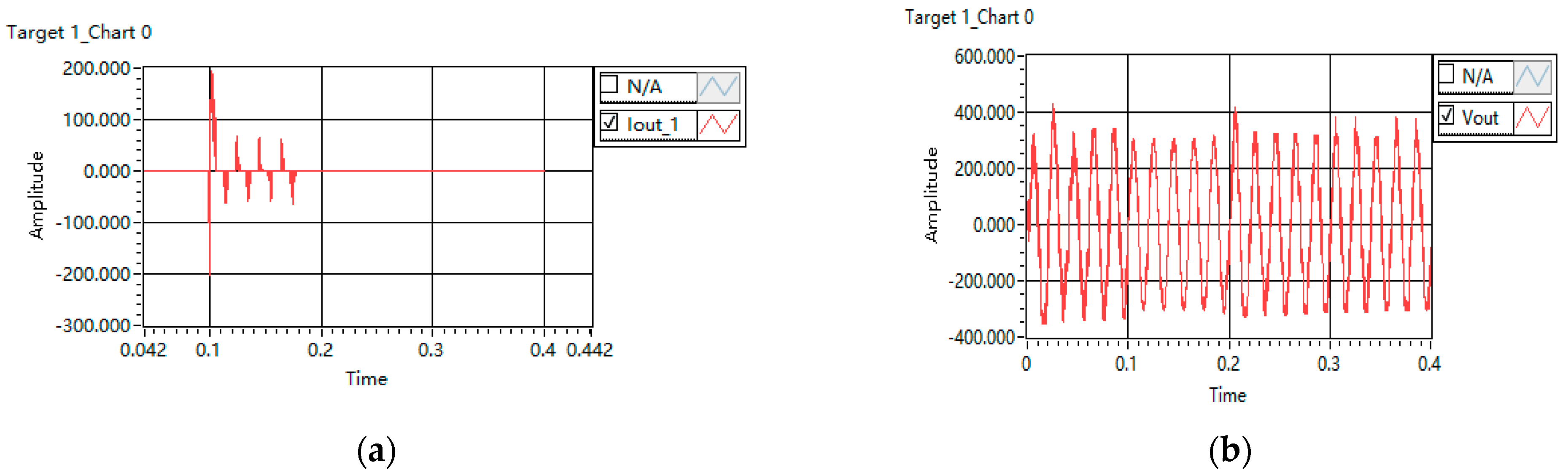
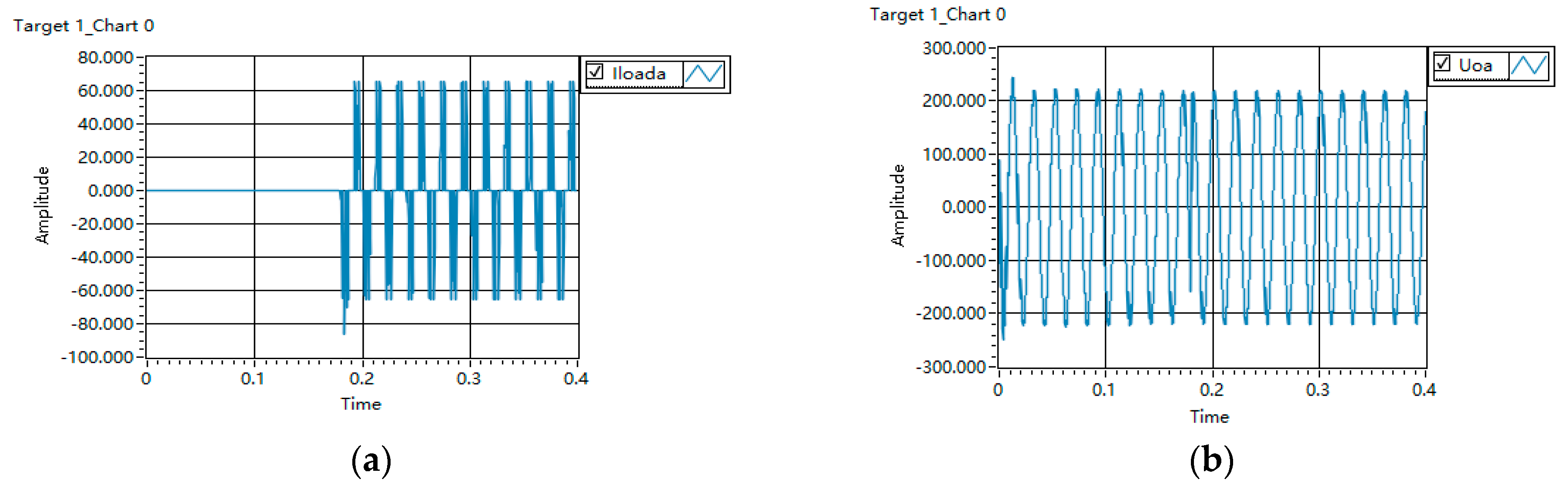
4.2. Experimental Results

The hardware in the loop real-time simulator is used in this experiment. As shown in Figure 13, the device includes the oscillograph, MT 6016 real-time simulator and DSP.
Figure 14 shows the waveforms of output current and output voltage which use current-limiting method when UPS is imposed on rectifier load.
In Figure 14a,b: output current of phase A i o A , output voltage of phase A U o A . At the time point t = 0.2 s, the UPS is imposed on rectifier load instantaneously: C r c = 2200 µ F, R r c = 16 Ω. It can be seen the current has severe distortion and the voltage becomes small and almost interruptible. The experimental results can be explained by current-limiting method: The current-limiting method by instantaneous current will force the reference value of current to be lowered or turn off all pulses when impulsive current occurs.
Figure 15 presents the experimental results of UPS which only uses the proposed dynamic switching method in this paper when the UPS is imposed on rectifier load.
In Figure 15a,b: output current of phase A i o A , output voltage of phase A U o A . At the time point t = 0.1 s, the UPS is imposed on instantaneous rectifier load: C r c = 2200 µ F, R r c = 16 Ω. It can be seen dynamic switching method will work immediately when the impulsive current occurs. The experimental results can be explained by the proposed control strategy: dynamic switching method improves the dynamic property of on- line UPS.
Figure 16 shows the waveforms of UPS output voltage which uses VSG control strategy combined with dynamic switching method when UPS is imposed on rectifier load. From top to bottom: output load current of phase A, output load voltage of phase A. At first, the UPS operates with steady state, At the time point t = 180 ms, the UPS is applied to instantaneous rectifier load: C r c = 2200 µF, R r c = 16 Ω. It can be seen that the waveforms of output voltage is smooth. The experimental results can be explained by the proposed dynamic control strategy: At the time point t = 180 ms, the UPS is imposed on instantaneous rectifier load, the huge impulsive current is sensed by the DSP and the supplying power to the load is switched from inverter to bypass power according to the dynamic switching sequence.

5. Conclusions

This paper presents an On-line UPS with pulse load control scheme based on VSG control strategy and dynamic switching method. VSG control strategy can provide inertia for UPS system by simulating the traditional synchronous generator, and the dynamic switching method can protect the UPS inverter from the damage of impulsive load. The simulation and experimental results show that the control strategy can effectively suppress the impulsive current, reduce the distortion of the output voltage of UPS inverter, and ensure the good performance of On-line UPS under impulsive load.
In this paper, a dynamic switching strategy based on VSG control is proposed for UPS connected to pulsive load, and the effectiveness of the proposed control strategy is verified from simulation and experiment. However, this research still needs to be improved: due to the limitation of experimental equipment, this paper only carries out the hardware in the loop simulation experiment for UPS inverter connected to pulsive load, and the experimental results may be different in actual situations. In the simulation process, the selected parameters can be further optimized through experiments.

Author Contributions

Conceptualization, G.H. and L.Z.; data curation, G.H. and L.Z.; formal analysis, G.H. and L.Z.; funding acquisition, G.H.; investigation, Y.D.; methodology, G.H. and L.Z.; project administration, G.H.; resources, G.H.; software, G.H. and L.Z.; supervision, G.H.; validation, L.Z. and W.Z.; visualization, G.L.; writing–original draft, G.H. and L.Z.; writing—review and editing, G.H. and L.Z. All authors have read and agreed to the published version of the manuscript.

Funding

This research was funded by Natural Science Fund Project of Henan Province, China, grant number 222300420400. Project name is new energy inverter grid system DC component suppression research. Project host is He Guofeng.

Data Availability Statement

The data presented in this research study are available in this article.

Conflicts of Interest

The authors declare no conflict of interest.

References

  1. Wang, G.; Wang, P. Rotor loss analysis of PMSM in flywheel energy storage system as uninterruptable power supply. IEEE Trans. Appl. Supercond. 2016, 26, 1–5. [Google Scholar]
  2. Aamir, M.; Mekhilef, S. An online transformerless uninterruptible power supply (UPS) system with a smaller battery bank for low-power applications. IEEE Trans. Power Electron. 2017, 32, 233–247. [Google Scholar] [CrossRef]
  3. Guillardi Junior, H.; Amaral Serni, P.J. A review of project of the controllers for an UPS. IEEE Latin Am. Trans. 2018, 16, 314–321. [Google Scholar] [CrossRef]
  4. Wang, S.; Gao, K.; Ge, Y.; Shi, Y.; Zhao, J.; Ju, R.; Ji, H. Discussion on the relationship between UPS battery connection method and its reliability. In Proceedings of the 2018 9th International Conference on Intelligent Control and Information Processing (ICICIP), Wanzhou, China, 9–11 November 2018. [Google Scholar]
  5. Abaray, S.; Beaver, S.; Nguyen, C. How reliable is your ups? Eliminating single points of failure. In Proceedings of the 2017 Petroleum and Chemical Industry Technical Conference (PCIC), Calgary, AB, Canada, 18–20 September 2017. [Google Scholar]
  6. Wei, Y.; Xu, Y.; Zou, J.; Li, Y. Current limit strategy for BLDC motor drive with minimized DC-link capacitor. IEEE Trans. Ind. Appl. 2015, 51, 3907–3913. [Google Scholar] [CrossRef]
  7. Chen, B.; Hsu, C.; Lai, Y. Novel current limitation technique without current feedback for digital-controlled battery charger in UPS applications. In Proceedings of the 2010 IEEE Energy Conversion Congress and Exposition, Atlanta, GA, USA, 12–16 September 2010. [Google Scholar]
  8. Wei, B.; Marzàbal, A.; Perez, J.; Pinyol, R.; Guerrero, J.M.; Vásquez, J.C. Overload and short-circuit protection strategy for voltage source inverter-based UPS. IEEE Trans. Power Electron. 2019, 34, 11371–11382. [Google Scholar] [CrossRef]
  9. Zhu, F.; Peng, Z.; Hu, W.; Wang, H.; Zhang, C.; Zhao, Z.; Dai, Y. An improved VSG control strategy for microgrid. In Proceedings of the 2021 IEEE International Conference on Electrical Engineering and Mechatronics Technology (ICEEMT), Qingdao, China, 2–4 July 2021. [Google Scholar]
  10. Yang, Y.; Wang, X.; Wang, Z.; Dong, X.; Yang, W.; Gao, Y. Research on control strategy of virtual synchronous generator based on energy storage wind farm. In Proceedings of the 2021 IEEE 5th Advanced Information Technology, Electronic and Automation Control Conference (IAEAC), Chongqing, China, 12–14 March 2021. [Google Scholar]
  11. Shao, Y.; Yang, R.; Li, X.; Chen, G. Battery energy storage system with energy spring based on VSG control strategy. In Proceedings of the 2019 10th International Conference on Power Electronics and ECCE Asia (ICPE 2019-ECCE Asia), Busan, Korea, 27–30 May 2019. [Google Scholar]
  12. Liu, D.; Zhong, Q.; Wang, Y.; Liu, G. Modeling and control of a V2G charging station based on synchronverter technology. CSEE J. Power Energy Syst. 2018, 4, 326–338. [Google Scholar] [CrossRef]
  13. Jun, F.; Meng, J. Modeling and parameter design of marine micro-grid virtual synchronous generator. In Proceedings of the 2021 IEEE 4th Advanced Information Management, Communicates, Electronic and Automation Control Conference (IMCEC), Chongqing, China, 18–20 June 2021. [Google Scholar]
  14. Marin-Hurtado, A.J.; Escobar-Mejía, A.; Alzate-Gómez, A.; Gil-González, W. Adaptive virtual synchronous machine applied to four-leg three-phase VSC. In Proceedings of the 2021 IEEE Southern Power Electronics Conference (SPEC), Kigali, Rwanda, 6–9 December 2021. [Google Scholar]
  15. Younis, T.; Ismeil, M.; Orabi, M.; Sayed, M.A.; Takeshita, T. Single-phase virtual synchronous generator without a dedicated synchronization unit. In Proceedings of the 2015 IEEE International Telecommunications Energy Conference (INTELEC), Osaka, Japan, 18–22 October 2015. [Google Scholar]
  16. Mir, A.S.; Senroy, N. Self-tuning neural predictive control scheme for Ultra-battery to emulate a virtual synchronous machine in autonomous power systems. IEEE Trans. Neural Netw. Learn. Syst. 2020, 31, 136–147. [Google Scholar] [CrossRef] [PubMed]
  17. Wu, H.; Ruan, X.; Yang, D.; Chen, X.; Zhao, X.; Lv, Z.; Zhong, Q. Small-signal modeling and parameters design for virtual synchronous generators. IEEE Trans. Ind. Electron. 2016, 63, 4292–4303. [Google Scholar] [CrossRef]
  18. Li, X.; Hu, Y.; Shao, Y.; Chen, G. Mechanism analysis and suppression strategies of power oscillation for virtual synchronous generator. In Proceedings of the IECON 2017 43rd Annual Conference of the IEEE Industrial Electronics Society, Beijing, China, 29 October–1 November 2017. [Google Scholar]
  19. Meng, X.; Liu, J.; Liu, Z. A generalized droop control for grid-supporting inverter based on comparison between traditional droop control and virtual synchronous generator control. IEEE Trans. Power Electron. 2019, 34, 5416–5438. [Google Scholar] [CrossRef]
  20. Cai, W.; Du, C.; Shi, Q.; Wang, G.; Wang, A.; Chui, D. An improved voltage control strategy based on finite-time theory for virtual synchronous generator. In Proceedings of the IECON 2021-47th Annual Conference of the IEEE Industrial Electronics Society, Toronto, ON, Canada, 13–16 October 2021. [Google Scholar]
  21. Xu, H.; Zhang, X.; Liu, F.; Shi, R.; Yu, C.; Cao, R. A reactive power sharing strategy of VSG based on virtual capacitor algorithm. IEEE Trans. Ind. Electron. 2017, 64, 7520–7531. [Google Scholar] [CrossRef]
  22. Wu, W.; Chen, Y.; Zhou, L.; Luo, A.; Zhou, X.; He, Z.; Yang, L.; Xie, Z.; Liu, J.; Zhang, M. Sequence impedance modeling and stability comparative analysis of voltage-controlled VSGs and current-controlled VSGs. IEEE Trans. Ind. Electron. 2019, 66, 6460–6472. [Google Scholar] [CrossRef]
  23. He, G.; Xu, D.; Yu, W.; Chen, M. A novel dynamic control strategy on resisting impulsive load for uninterruptible power supply system. In Proceedings of the 2013 28th Annual IEEE Applied Power Electronics Conference and Exposition (APEC), Long Beach, CA, USA, 17–21 March 2013. [Google Scholar]
Figure 1. Topology of on-line UPS.
Energies 15 04702 g001
Figure 2. Circuit diagram of half bridge DC/DC converter.
Energies 15 04702 g002
Figure 3. Topology of VSG.
Energies 15 04702 g003
Figure 4. Block diagram of VSG scheme.
Energies 15 04702 g004
Figure 5. Dynamic switching sequence for impulsive load.
Energies 15 04702 g005
Figure 6. Overall schematic diagram of on-line UPS with proposed control Scheme.
Energies 15 04702 g006
Figure 7. Simulation results of UPS with rectifier load using current limiting method (a) output current of phase A, (b) output voltage of phase A, (c) load pulse.
Energies 15 04702 g007
Figure 8. Simulation results of UPS with rectifier load using dynamic switching method (a) output current of phase A, (b) output voltage of phase A, (c) load pulse.
Energies 15 04702 g008
Figure 9. Simulation results of UPS with rectifier load using VSG control strategy and dynamic switching method (a) load current of phase A i o A , (b) load voltage of phase A U o A , C r c = 2200 µF, R r c = 16 Ω.
Energies 15 04702 g009
Figure 10. THD of output phase A voltage of UPS (a) UPS with current-limiting method, (b) UPS with dynamic switching method, (c) UPS with VSG control and dynamic switching method.
Energies 15 04702 g010
Figure 11. Simulation results of UPS with rectifier load using VSG control strategy and dynamic switching method (a) load current of phase A i o A , (b) load voltage of phase A U o A , C r c = 5500 µF, R r c = 16 Ω.
Energies 15 04702 g011
Figure 12. Simulation results of UPS with rectifier load using VSG control strategy and dynamic switching method (a) load current of phase A i o A , (b) load voltage of phase A U o A , C r c = 9900 µF, R r c = 16 Ω.
Energies 15 04702 g012
Figure 13. Structure diagram of hardware in the loop real-time simulator.
Energies 15 04702 g013
Figure 14. Experimental results of UPS with current-limiting method (a) output current of phase A, (b) output voltage of phase A.
Energies 15 04702 g014
Figure 15. Experimental results of UPS with only dynamic switching method (a) output current of phase A, (b) output voltage of phase A.
Energies 15 04702 g015
Figure 16. Experimental results of UPS with VSG control strategy combined with dynamic switching method (a) output load current of phase A, (b) output load voltage of phase A.
Energies 15 04702 g016
Table 1. Main circuit simulation parameters.
Parameter NameParameter Value
rated voltage220 V
rated frequency50 Hz
filter capacitor 80   ×   10 6 F
inverter side inductance 9   ×   10 3 H
switching frequency10 kHz
load side inductance 3   ×     10 3 H
Table 2. VSG controller parameters.
Parameter NameParameter Value
D p 5.1
D q 322
J0.04
K0.001
Publisher’s Note: MDPI stays neutral with regard to jurisdictional claims in published maps and institutional affiliations.

