1. Introduction
With the development of clean energy, natural gas plays an increasingly important role in China’s economy. However, China has become the world’s largest natural gas importer because its output cannot meet demand. With the increase in natural gas imports year by year, the demand for liquefied natural gas (LNG) as one of the natural-gas import channels is also increasing year by year [
1,
2,
3,
4,
5]. Therefore, how to ensure the transportation safety of liquefied natural gas (LNG) has become an important research question.
LNG submerged pumps are usually used for LNG transportation. The temperature of LNG liquid is −161 °C, and the drive motor for the pump needs to be immersed in an environment of −161 °C. Therefore, the drive motor for the pump is also called a submerged cryogenic motor. The operational performance of submerged cryogenic motors directly affects the transportation safety of LNGs [
6,
7,
8]. Natural gas is flammable and explosive. During LNG transportation, if the operating temperature of the submerged cryogenic motor is too high, the LNG is vaporized, which causes safety hazards. Therefore, it is necessary to control temperature increases in motor operations, reduce LNG gasification, and ensure transportation safety. To control the temperature increase in motor operations, the primary consideration is how to control the motor loss.
Foreign experts and scholars conducted research on cryogenic motors relatively early. The authors of [
9] focused on the design of a cryogenic induction motor considering the variation in the resistivity of the stator windings and rotor bars. Furthermore, the distribution of the magnetic flux density and magnetic saturation effect on the steel core were analyzed by using the 2-D finite-element method for alternating current (ac) sinusoidal time varying excitations under the VLT. The authors of [
10] presented the induction motor design technique, considering the resistivity variation at very low temperature. To derive the analysis of motor characteristics, it uses FEM analysis to obtain each motor-torque characteristic curve. The authors of [
11] conducted a comprehensive magnetic core characterization at a low temperature to determine the core properties and support filter design at low temperatures. The research on cryogenic motors in China started late and comprises few relevant studies, but there are still experts and scholars who have carried out research on cryogenic induction motors and cryogenic synchronous motors. The authors of [
12] calculated the running and mechanical characteristics of the cryogenic induction motor, and confirmed that the performance of the cryogenic induction motor is better than that of the room-temperature motor, its revolving speed is close to the synchronous speed, and its load capability is improved by controlling the constant-voltage frequency ratio. The authors of [
13] optimized the design of stator-flow ducts, discussed the effects of stator-edge distances and flow-hole widths on motor yoke magnetic potential and air gap flux density, and obtained the change rules of the motor yoke magnetic potential and air-gap flux density with different stator-flow ducts. The authors of [
14] designed a cryogenic permanent magnet synchronous motor, established a multiphysics model coupled with electromagnetic, fluid, thermal, and stress to analyze the performance of the motor, and verified the accuracy of the design. In the existing body of research, there are few studies on the loss of the cryogenic motor, let alone the method through which to reduce this loss.
In this paper, a cryogenic permanent magnet brushless DC motor is taken as an example. First, low-temperature and room-temperature experiments were carried out on the materials used in the motor, and the material properties at different temperatures were compared and analyzed according to the experiment data. Next, based on the material properties of the motor, the loss of the motor under different power supply modes, different temperatures, and different rotor structures was analyzed to explore the methods through which to reduce the loss of the cryogenic motor.
2. Low-Temperature Material Experiment
A submerged cryogenic permanent magnet brushless DC motor was designed. Since the motor needs to work in LNG at −161 °C, it is necessary to understand the properties of the materials used in the motor in low-temperature environments, in order to ensure that the materials can be used normally in such environments.
In this paper, ta 50W310 silicon-steel sheet was experimented on at room temperature and at a low temperature. The experimental instrument was IWATSU SY-8258 hysteresis-loop measurement instrument. Since LNG is flammable and explosive, in order to ensure the safety of the experiment, the low-temperature experiment in this paper was completed in a liquid-nitrogen environment (−196 °C). The room temperature experiment was completed at 20 °C. The measurement devices used in the room-temperature and low-temperature experiments are shown in
Figure 1 and
Figure 2.
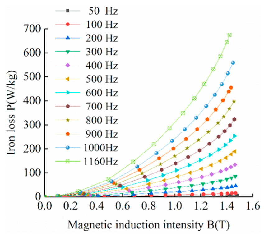
Firstly, the material properties of the 50W310 silicon-steel sheet were tested at room temperature. Next, the silicon-steel sheet was immersed in liquid nitrogen for one hour. After it became stable, the material properties at low temperatures were tested. The magnetization curve (BH curve) and iron-loss curve (BP curve) of 50W310 silicon-steel sheet are shown in
Figure 3,
Figure 4 and
Figure 5.
Figure 3 shows that the BH curve trends of 50W310 silicon-steel sheet at room temperature and low temperature are generally similar. The magnetic induction intensity B gradually increases with the increase in magnetic field intensity H and tends to gradually saturate. Under the same magnetic field intensity, the magnetic induction intensity of silicon-steel sheet at low temperature is always higher than that at room temperature. When the material is saturated, the magnetic induction intensity of the silicon-steel sheet at low temperature is 4.2% higher than that at room temperature.
Figure 4 and
Figure 5 show that the BP curve trends of 50W310 silicon-steel sheet at room temperature and low temperature are generally similar. The iron loss P increases gradually with the increase in magnetic induction intensity B. The iron loss P increases gradually with the increase in power supply frequency at the same temperature and magnetic induction intensity. By comparing the BP curves of silicon-steel sheet at room temperature and low temperature, it can be seen that the iron loss of silicon-steel sheet at low temperature is always higher than that at room temperature under the same power supply frequency and magnetic induction intensity. According to the experiment, the magnetic and conductive properties of 50W310 silicon-steel sheet are normal at low temperature. Therefore, 50W310 silicon-steel sheets can be used in this motor [
15].
According to relevant research, SmCo permanent magnet material does not lose magnetism in liquid nitrogen (−196 °C), and its remanence at low temperatures is slightly higher than at room temperature. It can be seen that SmCo permanent magnet material is less affected by low-temperature environments. Therefore, it can be used in this motor [
16]. In addition, the winding is another important component in the motor, and it is also one of the motor’s main heat sources. The relationship between copper conductivity
(S/m) and temperature
(°C) is:
Formula (1) shows that the conductivity of the winding increases with the decrease in the temperature. Therefore, the conductivity of the winding is better when the temperature is lower.
3. Cryogenic Permanent Magnet Brushless DC Motor
3.1. Parameters of Cryogenic Permanent Magnet Brushless DC Motor
In this paper, a 20-kilowatt submerged cryogenic permanent magnet brushless DC motor for LNG pumps is studied. The specific parameters are shown in
Table 1.
According to the parameters, a 2D model of the cryogenic permanent magnet brushless DC motor was established. The 1/4 model of the motor is shown in
Figure 6.
3.2. Power Supply Mode of Cryogenic Permanent Magnet Brushless DC Motor
There are two common power supply modes for permanent magnet brushless DC motors: three-phase inverter-circuit power supply (DC power supply) and PWM inverter-circuit power supply (PWM power supply).
The three-phase brushless DC motor system is shown in
Figure 7. The stator winding of the motor is three-phase star connection, and the position sensor is coaxial with the motor rotor. The control circuit generates the drive signal after the logical transformation of the position signal. After the drive signal is amplified by the drive circuit, it controls the power switch tube of the inverter to ensure that each phase winding of the motor works in a certain order. Different power supply modes have different control circuits. Each power supply mode can adjust the output voltage of the inverter circuit by changing the parameters of the control circuit.
The control circuit of the three-phase inverter circuit power supply is shown in
Figure 8, where
–
is a rectangular wave to provide a control signal and
–
is a voltmeter to measure the control signal.
–
, respectively, control
–
. When the control signal is positive, the corresponding power-switch tube is turned on. When the control signal is negative, the corresponding power-switch tube is turned off.
The control circuit of the PWM inverter-circuit power supply is shown in
Figure 9, where the modulation signal wave (
–
) is a sine wave, the carrier wave (
) is an isosceles-triangle wave, and
–
is a voltmeter to measure the control signal.
controls the on–off of
and
,
controls the on–off of
and
, and
controls the on–off of
and
. When the modulation signal wave is greater than the carrier wave, the control signal is positive, the power switch tube of the upper arm is turned on, and the power switch tube of the lower arm is turned off. When the modulation-signal wave is less than the carrier wave, the control signal is negative, the power switch tube of the lower arm is turned on, and the power switch tube of the upper arm is turned off. The waveform of the
phase-control circuit is shown in
Figure 10, where
is the modulation signal waveform,
is the carrier waveform, and
is the rectangular wave pulse providing the control signal.
4. Loss Analysis of Cryogenic Permanent Magnet Brushless DC Motor
In order to study the loss of each part of the cryogenic permanent magnet brushless DC motor, the motor in this paper adopted three-phase inverter-circuit power supply (DC power supply) and PWM inverter circuit power supply (PWM power supply) [
17], which were calculated at room temperature (20 °C) and at a low temperature (−196 °C).
The control circuits of the DC power supply and PWM power supply were set so that the control-circuit parameters of the same power supply mode under different temperatures were the same. After the finite element simulation calculation, when the DC power supply and PWM power supply were calculated, the loss data of each part of the motor under different temperatures were determined. They are shown in
Table 2.
In
Table 2, the rotor eddy current loss is the sum of each part of the eddy current loss of the rotor. Based on the data in
Table 2, the loss comparisons of each part of the motor under different power-supply modes and different temperatures are shown in
Figure 11.
As shown in
Figure 11, under the same power-supply mode, the stator iron losses of the motor at low temperatures are higher than that at room temperature, because the iron loss of the silicon-steel sheet at low temperatures is always higher than that at room temperature. Since the iron loss of the silicon-steel sheet is less affected by temperature under the motor operating frequency, the effect of the temperature on the stator iron losses is limited, and the difference values between the stator iron losses at different temperatures are controlled to within 20%. The rotor eddy current losses of the motor changes little at low temperatures and room temperature. Because the stator current harmonics and stator slot openings that cause the rotor eddy current loss are affected by temperature very little, the rotor eddy current losses are also affected by the temperature very little, and the difference values between the rotor eddy current loss at different temperatures are only within 2%. The winding copper losses of the motor at low temperatures are lower than at room temperature and change greatly. Because the resistivity of copper decreases with the decrease in temperature and is greatly affected by temperature, the winding copper loss is also greatly affected by temperature. The winding copper losses at room temperature are 6–8 times those at low temperatures.
As shown in
Figure 11, under the same temperature, the stator iron losses and the rotor eddy current losses of the motor under DC power supply are higher than those under PWM power supply and are greatly affected by the power-supply mode. The difference values between the stator iron loss and the rotor eddy current loss under different power supply modes are higher than 35%. The winding copper loss is less affected by the power-supply mode, and the difference values between the winding copper loss under different power-supply modes are within 20%.
The total losses of the motor at low temperatures are lower than at room temperature under the same power-supply mode. The total losses of the motor under DC power supply are higher than under PWM power supply at the same temperature. Therefore, PWM power supply can appropriately reduce motor loss and improve motor efficiency.
In this paper, the rotor eddy current loss of the motor is large, and the rotor eddy current loss is the largest under DC power supply. In order to reduce motor loss and motor temperature increase, we should mainly consider reducing the rotor eddy current loss.
5. Influence of Copper-Shielding Layer on Loss of Cryogenic Permanent Magnet Brushless DC Motor
5.1. Influence of Copper-Shielding Laye on Motor Loss
Since the rotor eddy current loss of the motor in this paper is large, and the rotor eddy current loss is highest under DC power supply, in order to reduce the rotor eddy current loss, the copper-shielding layer was added to the motor rotor. When adding the copper-shielding layer, it is necessary to keep the rotor outer diameter of motor and the thickness of the permanent magnet unchanged, and add the copper-shielding layer between the permanent magnet and the sleeve, in order for the increased thickness of the copper-shielding layer to be equal to the reduced thickness of the sleeve [
18,
19,
20]. Next, the rotor eddy current loss of motor with and without copper-shielding layer was compared and analyzed. DC power supply was adopted and the parameter setting of the control circuit was kept unchanged. The rotor eddy current density distribution cloud diagrams at room temperature (20 °C) and low temperature (−196 °C) are shown in
Figure 12 and
Figure 13.
Figure 12 and
Figure 13 show that after adding the copper-shielding layer to the rotor, the eddy current density on the sleeve and permanent magnet is greatly reduced, and the eddy current density on the copper-shielding layer is greatly increased. It can be seen that using a copper-shielding layer can effectively reduce the eddy current density of other parts of the rotor. The loss comparisons of each part of the motor with and without the copper-shielding layer at different temperatures are shown in
Table 3.
Figure 14 is based on the data in
Table 3.
As shown in
Figure 14, under the same temperature, the influence of the copper-shielding layer on the stator iron loss and the winding copper loss of the motor is very small and can be ignored. The copper shielding layer has a significant impact on the rotor eddy current loss of the motor. After using the copper-shielding layer, the rotor eddy current loss of the motor is greatly reduced. This is because the conductivity of the copper used in the shielding layer is greater than that of the sleeve and permanent magnet materials, so a large eddy current is generated in the copper-shielding layer, which can shield the sleeve and permanent magnet and reduce the rotor eddy current loss. After using the copper-shielding layer, the rotor eddy current loss at room temperature is reduced by 63.9%, and the rotor eddy current loss at low temperature is reduced by 89.6%. Due to the influence of the copper-shielding layer on the rotor eddy current loss, the total loss of the motor is also reduced. After using the copper-shielding layer, the total loss of the motor at room temperature is reduced by 25.2%, and the total loss of the motor at low temperature is reduced by 51.3%. It can be seen that the copper-shielding layer has a good inhibitory effect on the rotor eddy current loss of the motor, and can greatly reduce the rotor eddy current loss and the total loss of the motor. At the low temperature, the copper-shielding layer has a stronger inhibitory effect on the rotor eddy current loss, which can further reduce the rotor eddy current loss and the total loss of the motor.
5.2. Influence of Temperature on Copper-Shielding Layer
Since the copper-shielding layer has different inhibitory effects on the rotor eddy current loss at room temperature (20 °C) and at a low temperature (−196 °C), to further understand the influence of temperature on the copper-shielding layer, we calculated and analyzed the motor loss at temperatures of 20 °C, 0 °C, −10 °C, −40 °C, −70 °C, −100 °C, −130 °C, −161 °C, and −196 °C [
21]. In order to ensure the accuracy of the comparative analysis, a DC power supply was adopted and the parameter setting of the control circuit was kept unchanged. The loss comparisons of each part of the motor when the temperature changed after using the copper-shielding layer are shown in
Table 4.
Figure 15 is based on the data in
Table 4.
Figure 15 shows that after using the copper-shielding layer, the stator iron loss of the motor increases with the decrease in temperature, but the change range is small, which is due to the iron loss of the silicon-steel sheet increase with the decrease in temperature. The winding copper loss decreases with the decrease in temperature, which is due to the copper resistivity decreases in line with the decrease in temperature. With and without the copper-shielding layer, the changes in the stator iron loss and winding copper loss with temperature are practically the same, which is not repeated here. After using the copper-shielding layer, the rotor eddy current loss of the motor is the most affected by temperature.
Figure 16 shows that the copper conductivity increases with the decrease in temperature. When the temperature decreases, the conductivity difference values between the copper-shielding layer and other parts of the rotor increase gradually, which generates more eddy currents in the copper-shielding layer, resulting in a better shielding effect on other parts of the rotor. Therefore, the rotor eddy current loss of the motor decreases with the decrease in temperature. Since the rotor eddy current loss and winding copper loss of the motor decrease with the decrease in temperature, and the change range is large, the total loss of the motor also decreases with the decrease in temperature.
Figure 15 shows that the stator iron loss and the winding copper loss of the motor change approximately linearly with the temperature, while the rotor eddy current loss of the motor changes nonlinearly with the temperature. In order to facilitate the numerical calculation of the loss of each part of the motor at different temperatures, the curves of the stator iron loss, winding copper loss, and rotor eddy current loss in
Figure 15 are fitted to obtain the loss-fitting formula of each part of the motor.
Stator-iron loss-fitting formula:
Winding-copper loss-fitting formula:
Rotor-eddy-current loss -fitting formula:
where
PFe is the stator iron loss,
PCu is the winding copper loss,
Pe is the rotor eddy current loss, and
T is the temperature. The above formula is applicable to temperatures between 20 °C and −200 °C, and the error of the fitting formula is controlled to within 3.5%.
5.3. Influence of Shield Thickness on Motor Loss
In order to further explore the influence of the copper-shielding layer on the motor loss, the thickness of the copper-shielding layer was changed without changing the outer diameter of the rotor and the thickness of the permanent magnet, so that the increased thickness of the copper-shielding layer was equal to the reduced thickness of the sleeve. We calculated and analyzed the motor loss with copper-shielding thicknesses of 0.25 mm, 0.5 mm, 0.75 mm, 1 mm, 1.25 mm, 1.5 mm, and 1.75 mm [
22]. In order to ensure the accuracy of the comparative analysis, the DC power supply was adopted and the parameter setting of the control circuit was kept unchanged. When the thickness of the copper-shielding layer changed, the loss comparisons of each part of the motor at room temperature (20 °C) and at a low temperature (−196 °C) are shown in
Table 5 and
Table 6.
Figure 17 and
Figure 18 are based on the data in
Table 5 and
Table 6.
Figure 17 and
Figure 18 show that the stator iron loss and winding copper loss of the motor are not affected by the thickness of the shielding layer, while the rotor eddy current loss of the motor is greatly affected by the thickness of shielding layer. At room temperature and at a low temperature, the rotor eddy current loss of the motor first decreases in line with the increase in the shielding-layer thickness, and then increases in line with the increase in the shielding-layer thickness. However, at room temperature, the inflection point appears when the thickness of the copper-shielding layer is 1 mm, and the thickness of the copper-shielding layer is equal to that of the sleeve. At a low temperature, the inflection point appears when the thickness of the copper-shielding layer is 0.75 mm, and the thickness of the copper-shielding layer is 0.6 times the thickness of the sleeve. It can be seen that the thickness of the motor shielding layer should not be too large or too small. The thickness of the shielding layer should be 0.3–1.7 times the thickness of the sleeve at room temperature, and the thickness of the shielding layer should be 0.3–1 times the thickness of the sleeve at low temperature.
6. Conclusions
In this paper, the design of a cryogenic permanent magnet brushless DC motor was presented, and the motor loss was studied from the perspectives of power-supply mode, temperature, and shielding layer. The following conclusions were obtained:
Under the same power-supply mode, the total loss of the motor at a low temperature is lower than that at room temperature. Under the same temperature, the total loss of the DC power supply is higher than that of the PWM power supply;
The copper-shielding layer has a good inhibitory effect on the rotor eddy current loss of the motor, and can greatly reduce the rotor eddy current loss and the total loss of the motor. At the low temperature, the copper-shielding layer has a stronger inhibitory effect on the rotor eddy current loss, which can reduce the rotor eddy current loss and the total loss of the motor more significantly;
After using the copper-shielding layer, the stator iron loss and the winding copper loss of the motor change approximately linearly with the temperature, while the rotor eddy current loss of the motor changes nonlinearly with temperature. The calculation formulas of the stator iron loss, winding copper loss, and rotor eddy current loss are obtained by curve fitting;
The motor-shielding layer should not be too thick or too thin. The thickness of the shielding layer should be 0.3–1.7 times the thickness of the sleeve at room temperature, and the thickness of the shielding layer should be 0.3–1 times the thickness of the sleeve at low temperature.
The motor is a submerged cryogenic motor, which is mainly used for LNG transportation. Through this study, it was found that using an appropriate power-supply mode and shielding layer can effectively reduce the motor loss and control the motor-temperature increase, so as to reduce LNG gasification and improve transportation safety.
Author Contributions
Formal analysis, S.L.; Funding acquisition, B.G.; Investigation, D.T.; Methodology, S.L.; Project administration, Y.W. (Yue Wang); Supervision, P.H.; Validation, Y.W. (Yong Wang); Writing—original draft, S.L. All authors have read and agreed to the published version of the manuscript.
Funding
The article is based on the study funded by the National Basic Research Program.
Institutional Review Board Statement
Not applicable.
Informed Consent Statement
Not applicable.
Data Availability Statement
Not applicable.
Conflicts of Interest
The authors declare no conflict of interest.
References
- Zhou, S.; Zhu, J.; Shan, T.; Fu, Q.; Zhang, D.; Wang, J. Development status and outlook of natural gas and LNG industry in China. China Offshore Oil Gas 2022, 34, 1–8. [Google Scholar]
- Xia, X. Review of global gas market in 2021 and prospect for 2022. Int. Pet. Econ. 2022, 30, 28–35. [Google Scholar]
- Li, W.; Wang, Y. The development trend and impact of global carbon-neutral LNG trade. Int. Pet. Econ. 2022, 30, 72–79. [Google Scholar]
- Animah, I.; Shafuee, M. Application of risk analysis in the liquefied natural gas (LNG) sector: An overview. J. Loss Prev. Process Ind. 2020, 63, 103980. [Google Scholar] [CrossRef]
- Al-Kuwari, O.; Schnfisch, M. The Emerging Hydrogen Economy and its Impact on LNG. EWI Work. Pap. 2022, 47, 2080–2092. [Google Scholar] [CrossRef]
- Wood, D.A.; Kulitsa, M. Weathering/Ageing of Liquefied Natural Gas Cargoes During Marine Transport and Processing on Floating Storage Units and FSRU. J. Energy Resour. Technol. 2018, 140, 102901. [Google Scholar] [CrossRef]
- Luo, T.; Yu, C.; Liu, R.; Li, M.; Zhang, J.; Qu, S. Numerical simulation of LNG release and dispersion using a multiphase CFD model. J. Loss Prev. Process Ind. 2018, 56, 316–327. [Google Scholar] [CrossRef]
- Ai, C.; Huang, Y.; Wang, H.; Gu, G. Development of the Cryogenic Electrical Motor for the Submerged Liquid Natural Gas Pump and Its Key Technologies. Proc. CSEE 2014, 34, 2396–2405. [Google Scholar]
- Kim, H.M.; Lee, K.W.; Kim, D.G.; Park, J.H.; Park, G.S. Design of Cryogenic Induction Motor Submerged in Liquefified Natural Gas. IEEE Trans. Magn. 2018, 54, 1–4. [Google Scholar]
- Kim, B.J.; Lee, K.W.; Park, G.S. Design of a Very Low Temperature Induction Motor for Liquid Nitrogen Gas Pump. In Proceedings of the 2013 International Conference on Electrical Machines and Systems, Busan, Korea, 26–29 October 2013. [Google Scholar]
- Chen, R.; Dong, Z.; Zhang, Z.; Gui, H.; Niu, J.; Ren, R.; Wang, F.; Tolbert, L.M.; Blalock, B.J.; Costinett, D.J.; et al. Core Characterization and Inductor Design Investigation at Low Temperature. In Proceedings of the 2018 IEEE Energy Conversion Congress and Exposition, Portland, OR, USA, 23–27 September 2018. [Google Scholar]
- Ai, C.; Huang, Y.; Wang, H.; Gu, G. Research on the Operating Performance of an Inverter-driven Cryogenic Induction Motor for a Submerged LNG Pump. Trans. China Electrotech. Soc. 2015, 30, 138–145. [Google Scholar]
- Huang, Y.; Ai, C.; Wang, H. Optimization Design of Flow Ducts in Submerged Liquefied Natural Gas Pump Cryogenic Motor. Proc. CSEE 2015, 35, 6535–6542. [Google Scholar]
- Guo, C.; Huang, S.; Wang, J.; Feng, Y. Research of Cryogenic Permanent Magnet Synchronous Motor for Submerged Liquefified Natural Gas Pump. IEEE Trans. Energy Convers. 2018, 33, 2030–2039. [Google Scholar] [CrossRef]
- Lv, X.; Sun, D.; Sun, L. Determination of Iron Loss Coefficients of Ferromagnetic Materials Used in Cryogenic Motors. In Proceedings of the 2019 22nd International Conference on Electrical Machines and Systems, Harbin, China, 11–14 August 2019. [Google Scholar]
- Guo, C.; Huang, S.; Wang, J.; Feng, Y. Design and Characteristic Research of Submerged Cryogenic Permanent Magnet Synchronous Motor. Trans. China Electrotech. Soc. 2019, 34, 3769–3777. [Google Scholar]
- Xie, E.; Liu, W.; Luo, L.; Wang, P. Influence of PWM on Rotor Eddy-Current Losses in Brushless DC Motor. Trans. China Electrotech. Soc. 2013, 28, 117–125. [Google Scholar]
- Zhang, Z.; Deng, Z.; Sun, Q.; Xu, Z.; Li, K. Influences of Copper Shield on Eddy-current Loss and Stress for a Rotor of High-speed PM BLDC Motor. Proc. CSEE 2018, 38, 2476–2486. [Google Scholar]
- Zhou, F.; Shen, J.; Fei, W.; Lin, R. Study of Retaining Sleeve and Conductive Shield and Their Inflfluence on Rotor Loss in High-Speed PM BLDC Motors. IEEE Trans. Magn. 2006, 42, 3398–3400. [Google Scholar] [CrossRef]
- Shen, J.; Han, T.; Yao, L.; Wang, Y. Is Higher Resistivity of Magnet Beneficial to Reduce Rotor Eddy Current Loss in High-Speed Permanent Magnets AC Machines. Trans. China Electrotech. Soc. 2020, 35, 2074–2077. [Google Scholar]
- Zhuo, L.; Sun, L.; Shi, D.; Sun, R.; Zou, J. Semi-analytical Model and Experimental Verification of Rotor Eddy Current Loss of High Temperature High Speed Permanent Magnet Machine Considering Temperature Change. Proc. CSEE 2021, 41, 8305–8314. [Google Scholar]
- Han, T. Influence of Various Rotor Structures on Rotor Eddy Current Loss in High-Speed PM Brushless Motor; Zhejiang University: Hangzhou, China, 2020. [Google Scholar]
Figure 1.
Material measurement device in room-temperature environment.
Figure 1.
Material measurement device in room-temperature environment.
Figure 2.
Material measurement device in low-temperature environment.
Figure 2.
Material measurement device in low-temperature environment.
Figure 3.
BH curves of 50W310 silicon-steel sheet at different temperatures.
Figure 3.
BH curves of 50W310 silicon-steel sheet at different temperatures.
Figure 4.
BP curve of 50W310 silicon-steel sheet at 20 °C.
Figure 4.
BP curve of 50W310 silicon-steel sheet at 20 °C.
Figure 5.
BP curve of 50W310 silicon-steel sheet at −196 °C.
Figure 5.
BP curve of 50W310 silicon-steel sheet at −196 °C.
Figure 6.
2D model diagram of cryogenic permanent magnet brushless DC motor.
Figure 6.
2D model diagram of cryogenic permanent magnet brushless DC motor.
Figure 7.
The three-phase brushless DC motor system.
Figure 7.
The three-phase brushless DC motor system.
Figure 8.
The control circuit of three-phase inverter-circuit power supply.
Figure 8.
The control circuit of three-phase inverter-circuit power supply.
Figure 9.
The control circuit of PWM inverter-circuit power supply.
Figure 9.
The control circuit of PWM inverter-circuit power supply.
Figure 10.
The waveform of the VS1 phase-control circuit.
Figure 10.
The waveform of the VS1 phase-control circuit.
Figure 11.
Comparison diagram of motor loss under different power-supply modes and different temperatures.
Figure 11.
Comparison diagram of motor loss under different power-supply modes and different temperatures.
Figure 12.
The rotor eddy current-density distribution cloud diagram at room temperature.
Figure 12.
The rotor eddy current-density distribution cloud diagram at room temperature.
Figure 13.
The rotor eddy current-density distribution cloud diagram at low temperature.
Figure 13.
The rotor eddy current-density distribution cloud diagram at low temperature.
Figure 14.
Comparison diagram of motor loss with and without shielding layer at different temperatures.
Figure 14.
Comparison diagram of motor loss with and without shielding layer at different temperatures.
Figure 15.
Comparison diagram of motor loss at various temperatures.
Figure 15.
Comparison diagram of motor loss at various temperatures.
Figure 16.
Variation diagram of copper conductivity with temperature.
Figure 16.
Variation diagram of copper conductivity with temperature.
Figure 17.
Comparison diagram of motor loss with different shielding-layer thicknesses at 20 °C.
Figure 17.
Comparison diagram of motor loss with different shielding-layer thicknesses at 20 °C.
Figure 18.
Comparison diagram of motor loss with different shielding-layer thicknesses at −196 °C.
Figure 18.
Comparison diagram of motor loss with different shielding-layer thicknesses at −196 °C.
Table 1.
Cryogenic permanent magnet brushless DC motor parameters.
Table 1.
Cryogenic permanent magnet brushless DC motor parameters.
| Design Parameter | Value |
|---|
| Rated power/kW | 20 |
| Rated voltage/V | 380 |
| Rated speed/rpm | 10,000 |
| Stator outter diameter/mm | 133 |
| Stator inner diameter/mm | 76 |
| Rotor outter diameter/mm | 60 |
| Rotor inner diameter/mm | 30 |
| PM thickness/mm | 4.5 |
| Rotor-Sleeve Thickness/mm | 2 |
| Stator slot number | 24 |
| Number of pole pairs | 2 |
Table 2.
Motor-loss data under different power-supply modes and different temperatures.
Table 2.
Motor-loss data under different power-supply modes and different temperatures.
| Parameter | Value | Value | Value | Value |
|---|
| Power-supply mode | DC | DC | PWM | PWM |
| Temperature (°C) | −196 | 20 | −196 | 20 |
| Output Power (kW) | 20.8 | 21.5 | 20.2 | 19.37 |
| Torque (N·m) | 19.9 | 20.5 | 19.3 | 18.51 |
| Stator iron loss (W) | 381.5 | 347.8 | 281.1 | 238.7 |
| Rotor eddy current loss (W) | 599.9 | 591.9 | 411.6 | 403.7 |
| Winding copper loss (W) | 65.7 | 502.3 | 66.5 | 423 |
| Total loss (W) | 1047.1 | 1442 | 759.2 | 1065.4 |
Table 3.
Motor-loss data with and without shielding layer at different temperatures.
Table 3.
Motor-loss data with and without shielding layer at different temperatures.
| Parameter | Value | Value | Value | Value |
|---|
| Power-supply mode | DC | DC | DC | DC |
| Shielding layer thickness (mm) | 0 | 0.5 | 0 | 0.5 |
| Temperature (°C) | 20 | 20 | −196 | −196 |
| Output Power (kW) | 21.5 | 21.4 | 20.8 | 20.4 |
| Torque (N·m) | 20.5 | 20.4 | 19.9 | 19.5 |
| Stator iron loss (W) | 347.8 | 349 | 381.5 | 381.7 |
| Rotor eddy current loss (W) | 591.9 | 213.7 | 599.9 | 62.3 |
| Winding copper loss (W) | 502.3 | 516.3 | 65.7 | 66.3 |
| Total loss (W) | 1442 | 1079 | 1047.1 | 510.3 |
Table 4.
Motor-loss data at various temperatures.
Table 4.
Motor-loss data at various temperatures.
| Parameter | Value | Value | Value | Value | Value | Value | Value | Value | Value |
|---|
| Power supply mode | DC | DC | DC | DC | DC | DC | DC | DC | DC |
| Shielding layer thickness (mm) | 0.5 | 0.5 | 0.5 | 0.5 | 0.5 | 0.5 | 0.5 | 0.5 | 0.5 |
| Temperature (°C) | 20 | 0 | −10 | −40 | −70 | −100 | −130 | −161 | −196 |
| Output Power (kW) | 21.4 | 21.3 | 21.3 | 21.1 | 21 | 20.8 | 20.7 | 20.6 | 20.4 |
| Torque (N·m) | 20.4 | 20.3 | 20.3 | 20.2 | 20 | 19.9 | 19.8 | 19.7 | 19.5 |
| Stator iron loss (W) | 349 | 352 | 353.2 | 357.6 | 362.3 | 367 | 371.7 | 376.5 | 381.7 |
| Rotor eddy current loss (W) | 213.7 | 202.7 | 197.2 | 180.4 | 162.8 | 143.7 | 122.6 | 96.6 | 62.3 |
| Winding copper loss (W) | 516.3 | 476.1 | 454.5 | 392.7 | 330.9 | 266.9 | 204.1 | 139.2 | 66.3 |
| Total loss (W) | 1079 | 1030.8 | 1004.9 | 930.7 | 856 | 777.6 | 698.4 | 612.3 | 510.3 |
Table 5.
Motor-loss data with different shielding-layer thicknesses at 20 °C.
Table 5.
Motor-loss data with different shielding-layer thicknesses at 20 °C.
| Parameter | Value | Value | Value | Value | Value | Value | Value |
|---|
| Power-supply mode | DC | DC | DC | DC | DC | DC | DC |
| Shielding-layer thickness (mm) | 0.25 | 0.5 | 0.75 | 1 | 1.25 | 1.5 | 1.75 |
| Temperature (°C) | 20 | 20 | 20 | 20 | 20 | 20 | 20 |
| Output Power (kW) | 21.6 | 21.4 | 21.4 | 21.3 | 21.3 | 21.3 | 21.2 |
| Torque (N·m) | 20.6 | 20.4 | 20.4 | 20.4 | 20.3 | 20.3 | 20.3 |
| Stator iron loss (W) | 349.3 | 349 | 349.4 | 349.3 | 349.3 | 349.4 | 349.4 |
| Rotor eddy current loss (W) | 302.6 | 213.7 | 186.5 | 181.5 | 192.9 | 220.3 | 266.8 |
| Winding copper loss (W) | 520.6 | 516.2 | 515.8 | 515.5 | 515.9 | 516.8 | 518.1 |
| Total loss (W) | 1172.5 | 1078.9 | 1051.7 | 1046.3 | 1058.1 | 1086.5 | 1134.3 |
Table 6.
Motor-loss data with different shielding-layer thicknesses at −196 °C.
Table 6.
Motor-loss data with different shielding-layer thicknesses at −196 °C.
| Parameter | Value | Value | Value | Value | Value | Value | Value |
|---|
| Power supply mode | DC | DC | DC | DC | DC | DC | DC |
| Shielding layer thickness (mm) | 0.25 | 0.5 | 0.75 | 1 | 1.25 | 1.5 | 1.75 |
| Temperature (°C) | −196 | −196 | −196 | −196 | −196 | −196 | −196 |
| Output Power (kW) | 20.5 | 20.4 | 20.5 | 20.5 | 20.5 | 20.6 | 20.6 |
| Torque (N·m) | 19.6 | 19.5 | 19.5 | 19.6 | 19.6 | 19.7 | 19.7 |
| Stator iron loss (W) | 381.6 | 381.7 | 381.8 | 382 | 382.3 | 382.5 | 382.7 |
| Rotor eddy current loss (W) | 89.2 | 62.3 | 61.4 | 72.1 | 89.7 | 113.1 | 142.9 |
| Winding copper loss (W) | 66.3 | 66.3 | 66.4 | 66.7 | 67.2 | 68 | 68.4 |
| Total loss (W) | 537.1 | 510.3 | 509.6 | 520.8 | 539.2 | 563.6 | 594 |
| Publisher’s Note: MDPI stays neutral with regard to jurisdictional claims in published maps and institutional affiliations. |
© 2022 by the authors. Licensee MDPI, Basel, Switzerland. This article is an open access article distributed under the terms and conditions of the Creative Commons Attribution (CC BY) license (https://creativecommons.org/licenses/by/4.0/).


