Abstract
This paper presents the design, modeling, and control of a hybrid multi-degree-of-freedom motor (HMDOF motor) that can be applied to unmanned aerial vehicles, such as drones. The HMDOF motor has a rotating motor and tilting motors separately and enables multi-DOF movement by driving each motor. In addition, owing to its structural characteristics, it is designed to allow a 3- or 6-DOF movement in only one motor. In this study, the control performance of an HMDOF motor was verified using simulated and experimental results. The position control performance for the rotation speed of the rotating motor was verified, and the control performance of the motor under the speed of the rotating motor and disturbance on tilting motors were analyzed.
1. Introduction
In recent years, there has been widespread usage of equipment incorporating multi-degree-of-freedom (DOF) drive systems, such as cameras gimbals, drones, or robot arms. Additionally, work processes using multi-DOF systems are more sophisticated, in comparison to normal. Generally, multi-DOF systems comprise of many connected motors with gears and frames, i.e., as many as the DOF number. Therefore, they are larger and heavier because of the additional motors and have the disadvantage of mechanical loss caused by the gears [1,2,3].
For example, a quadcopter has six DOFs for controlling the thrust of the four rotors. The size of the quadcopter can be designed to be compatible with that of the system; however, there is a limit to size minimization because four or more rotors are necessary. Additionally, as the four rotors rotate organically to control the quadcopter, complete breakdown of even a single rotor makes it is very difficult to control the remaining rotors. Therefore, a system in which each rotor can move independently has been developed by using tilting rotors or flexible frames [4,5,6,7,8,9].
Research has been conducted on realizing a system capable of driving multi-DOF motors [10,11,12,13,14,15]. One such study on driving a multi-DOF system involves a spherical motor. A spherical motor can rotate with a tilted shaft unlike the fixed axis rotation of a conventional motor. Therefore, research is being actively conducted to implement a multi-DOF system with a spherical motor. However, owing to the spherical shape of the motor, it is very difficult to manufacture a spherical stator and to wind a coil around it.
In this paper, a hybrid multi-DOF motor (HMDOF motor) is presented for driving a multi-DOF system [16,17,18]. Unlike a spherical motor, in which all coils are responsible for the tilting and rotational motion, an HMDOF motor is designed with a ‘rotating motor’ in charge of rotating motion and ‘tilting motors’ in charge of tilting motion, respectively. However, as the entire tilting motor is surrounded by a rotating motor, it appears as if a single motor is rotating and tilting. This motor is called the “hybrid” type because the rotating motor can be easily detached and changed into a structure that can only be tilted. The motor shaft can be tilted to control the thrust of an attached propeller in the desired direction. A quadcopter with an HMDOF possesses 6-DOF movement using only one rotor. In addition, drones designed using two or more HMDOM motors have the advantage of being able to switch to fault-tolerant control, even if one rotor fails, because a single rotor can both tilt and rotate.
One of the characteristics of the HMDOF motor is that the mathematical modeling of the motor requires only simple rotational transformations. Assuming that the body frame of the motor is fixed, the coordinate systems of the HMDOF motor can be divided into fixed-body, tilting plane, and rotating motor coordinate frames, respectively. The description of each coordinate system is discussed in detail in Section 3.1. Assuming that the centers of all coordinate systems are designed to be the same, system modeling is possible using simple transformation matrices.
Torque characteristics according to the shape of the tilting motor were compared in the previous study [16]. In the reference [16], voice coil and SPMSM type tilting motors were designed and manufactured, and the holding torque (tilting torque) was compared without the rotating motor. Therefore, this paper shows the control performance with the SPMSM type tilting motors through simulation and experiment when the rotating motor is rotating at a constant speed.
In this paper, the structure details of an HMDOF motor are introduced, and the system modeling is presented. First, the coordinate system set by the parts of the HMDOF and the system values in each coordinate system were defined and system dynamic equations represented. Owing to the shaft of this motor tilting and rotating simultaneously, it was essential to consider the torque due to the gyro effect in the motion equation, so that the modeling of the motor incorporated the torque equations as well. In addition, a control algorithm was designed based on the modeling of the motor, and the position control results were verified and compared through simulations and experiments. Moreover, the control robustness was verified through an experimental test to apply the disturbances. Finally, position control tests of the motor were performed at varying rotation speeds to demonstrate the position control performance of the motor.
2. Structure and Design of the HMDOF Motor
2.1. Structure of the HMDOF Motor
Figure 1a shows the entire HMDOF motor, which is divided into inner and outer structures [16,17]. The inner structure includes the tilting motors responsible for the tilting movement and frames with a universal joint and the outer structure includes a rotating motor responsible for the rotational movement.
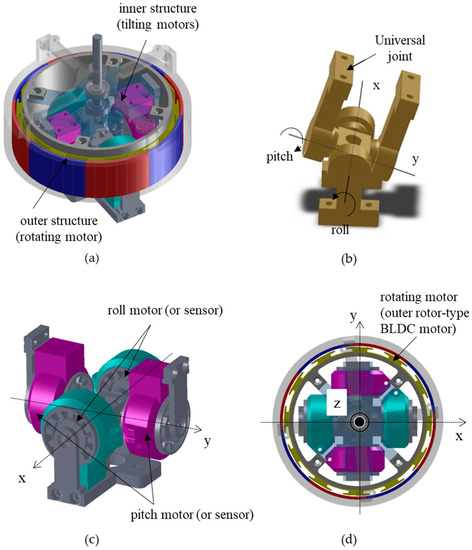
Figure 1.
Structure of the HMDOF motor: (a) The whole structure; (b) The universal joint; (c) The inner structure; (d) The top view of the whole structure.
Figure 1b shows the universal joint, which is a key part of the inner structure. In Figure 1b, the roll is the rotating angle about the x-axis and yaw is the rotating angle about the y-axis. Figure 1c shows the entire inner structure, including the tilting motors for roll and pitch rotation, position sensors for motors, and the universal joint. In addition, a motor mounted in the roll and pitch direction is called a ‘roll motor’ and a ‘pitch motor’, respectively, and the two motors are called ‘tilting motors’. The part of the roll motor that can be fixed to the ground is called ‘the fixed inner structure’, and the movable part with the pitch-axis motor is called ‘the moving inner structure’. Each part had two frames for mounting the motors or position sensors and had two identical tilting motors to generate twice the torque. However, in this study, only one tilting motor and one position sensor were used for precision position control using vector control.
Figure 1d shows the top view of the HMDOF motor, wherein the rotating motor is designed as an outer rotor-type brushless DC (BLDC) motor so that it can be installed around the inner structure. Therefore, although there are three motors, the overall size of the motor can be optimized. The stator of the rotating motor is fixed to the upper plane of the universal joint, called ‘the tilting plane’, and the rotor of the rotating motor is connect-ed to a bearing, such that it can rotate based on the center of the tilting plane’.
Meanwhile, as shown in Figure 1b,c, the roll motor is fixed to the ground, and the structure, including the pitch motor, is rotated by the roll motor rotation. Moreover, the tilting angle of the tilting plane about the ground was determined by the rotation of the tilting motors.
2.2. Details of the Tilting Motor
Figure 2 shows the inner structure of the HMDOF motor, which includes a universal joint, tilting motors, resolvers, and a tilting plane (the upper plane of the inner structure). A surface permanent magnet synchronous motor (SPMSM) was selected for the tilting motor. It is important to design the inner structure to have an appropriate tilting angle and torque motor’s target, as the tilting angle range is limited by the size of the inner structure. Although the design process of the tilting motor is similar to that of conventional motors, the design goal of the tilting motor is to obtain the maximum holding torque for position control rather than the rotating speed or torque. Additionally, size minimization and weight is an additional design goal of the multi-DOF motor for optimizing the system size and weight.
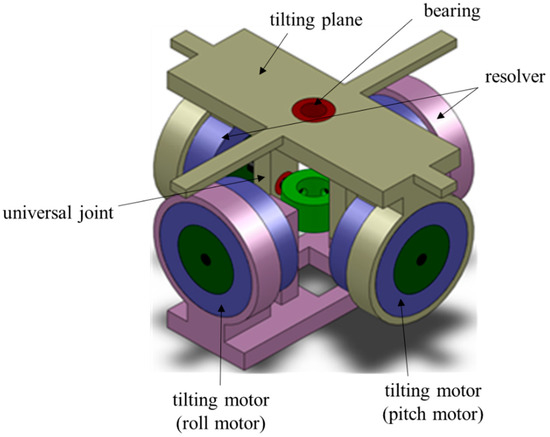
Figure 2.
Inner structure of the HMDOF motor.
The specifications of the designed tilting motor are presented in Table 1. The SPMSM for the tilting motor was designed as a three-phase motor with 8 poles and 12 slots. Details of the SPMSM are presented in Table 1. The SPMSM had an outer diameter of 30 mm and a stacking of 15 mm. The rated voltage was 12 V, and the designed operating angle ranged from −30° to 30°. However, the actual operating range was only −15° to 15°.

Table 1.
SPMSM specifications for tilting motors.
2.3. Details of the Rotating Motor
Figure 3 shows the rotating motor. It was designed as an outer rotor-type BLDC motor with a hollow center to match the size of the inner structure. The stator of the rotating motor was installed on the tilting plane of the moving inner structure, and the shaft was connected to the center of the tilting plane with a bearing.
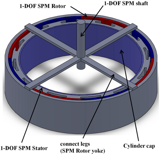
Figure 3.
Rotating motor of the HMDOF motor.
The rated output of the rotating motor was 0.5 Nm at 3000 rpm. Unlike a tilting motor designed for precise position control, the goal of a rotating motor is to control the rotation-al speed. For speed control, sensorless control for the BLDC motor using 120° conduction mode was selected [19,20,21]. Moreover, in the case of this motor design, the rotating motor design process was constrained by the inner diameter, as it initiated only after the size of the inner structure was predetermined. The voltage limit of the rotating motor was set to 12 V, so that the same power supply that drove the tilting motors could be used.
The rotating motor was designed as a three-phase motor with 28 poles and 24 slots, with the details listed in Table 2. The motor had an outer diameter of 107.5 mm and a stacking of 20 mm. In addition, the inner diameter of the motor was 90 mm, and the inner structure could be inserted into the hollow of the rotating motor. For the rotating motor, the shaft was connected to the inner structure to support the rotor of the rotating motor. Therefore, to maintain a constant air gap, it was important to assemble the entire structure carefully.
Table 2.
Motor specifications for the rotating motor.
3. Modeling for HMDOF Motor Simulation
3.1. Coordinate System of the HMDOF Motor
Assuming that the ‘fixed inner structure’ of the HMDOF motor is fixed in a specific position and does not move, the coordinate system of the motor can be divided into three categories as follows: the fixed body reference coordinate system (F-frame), ‘the moving inner structure’ reference coordinate system (T-frame), and the coordinate system of the rotor of the rotating motor (R-frame).
The F-frame indicates the coordinate system based on the fixed inner structure, and the roll-axis motor is driven based on the F-frame. Assuming that the fixed inner structure does not rotate or move, it is the same as that in the ground coordinate system. The T-frame represents a coordinate system based on a moving inner structure. The pitch motor was driven based on the T-frame. The R-frame represents a coordinate system based on the rotor of the rotating motor. The stator of the rotating motor was fixed to the T-frame. Assuming that the origins of the three coordinate systems are the same, the physical quantities of the HMDOF motor on the three coordinate systems can be represented on any frame through transformations, using only the rotation matrices.
Figure 4a shows the roll () pitch (), and yaw () direction of the HMDOF motor. It assumed the rotating motor is rotating with the speed of . Additionally, the relation of F- and T-Frames is shown in Figure 4b, wherein the shaft of the rotating motor moves from the solid red arrow to the dotted red arrow. The T-frame is moved with the shaft. Additionally, the shaft position of the rotating motor is represented in the Euler angle, as shown in Figure 4b. The coordinate systems are described in detail following equations.
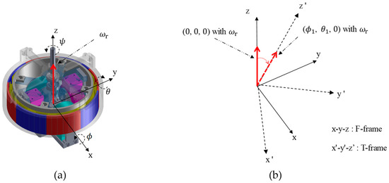
Figure 4.
Coordinate systems of the HMDOF motor: (a) Euler angles of the HMDOF; (b) The relationship of F- and T- frame.
The rotation matrix for converting the physical quantities of the T-frame to the F-frame coordinate system is defined by Equations (1) and (2), according to the Euler transformation [22,23,24,25,26].
where are the Euler angles on F-frame.
The angular velocity based on the F-frame is derived as Equation (3) using the derivative of the Euler angles.
In Equation (3), is the Euler angles on F-frame and is a matrix that converts the derivative of Euler angles on the F-frame to the angular velocity of the T-frame, as shown in Equation (4).
3.2. Torque Equations of the HMDOF Motor
The equation of motion for the HMDOF motor can be divided into the equations of motion for the tilting motors in the T-frame and the rotating motor in the R-frame, respectively. The equation of motion of the tilting motors is given by Equation (5) in the T-frame [22,23,24,25,26].
where is the total torque of the tilting motors and is the rotational speed of the moving inner structure. Additionally, considering that the tilting motors are driven symmetrically along the x- and y-axes in the T-frame, and the rotating motor only rotates about the z-axis, the moment of inertia of the HMDOF motor, including the rotating motor (), can be expressed as .
Moreover, as the rotating motor rotates is based on the z-axis in the T-frame, the equation of motion by the rotating motor in the T-frame can be given in the following Equation (6) as
where is the torque of the rotating motor, is the moment of inertia of the rotor of the rotating motor, and is the rotational speed of the rotating motor. Since is a constant and , Equation (6) can be rewritten as Equation (7):
In Equation (7), the rotating motor rotates along the z-axis in the T-frame, wherein the gyroscopic effect must be considered. The equation of motion owing to the gyro effect in the T-frame is given by Equation (8) as
where denotes the angular momentum of the rotating motor. The rotating motor has only the z-component of the angular momentum, and the rotating motor, including the moving inner structure, can be tilted along the roll and pitch directions. Therefore, and are given by Equation (9) as
Equation (10) is written using Equations (8) and (9) as
Considering Equation (10), Equation (5) is rewritten as Equation (11) as
Equation (12) is the torque equation in the F-frame, which can be obtained by con-verting Equation (11) using the transformation matrices of Equations (2) and (3),
Finally, the equation of motion for the HMDOF motor was obtained in the F-frame. In the next section, we derive the torque equation of the motor from the voltage equation of each motor, and the simulation was performed using the motion equation of the HMDOF motor, based on Equation (12).
3.3. Torque Equation of the Tilting Motor
As mentioned above, tilting and rotating motors were designed as SMPSM. Additionally, the tilting motors, including the roll and pitch motors, were controlled using vector control for precise position control. To use vector control, the rotor position was measured by the resolver, and the current values of the three phases were measured using cur-rent transducers. Therefore, position control was precise and efficient, as it was possible to determine the exact position of the rotor of the tilting motors and generate the desired torque.
The following shows the process of deriving the d–q-axis voltage equation from the three-phase voltage equation for one of the tilting motors and represents the torque equation from the q-axis current. First, the voltage equation of the three-phase SPMSM can be expressed as Equation (13).
where is the phase voltage, is the phase current, is the phase resistance, and is the permanent magnet flux linking the stator winding. In addition, is the self-inductance of the stator winding in Equation (14)
Equation (13) can be converted into the voltage equation of the d–q-axis in Equation (16) using the transformation matrix in Equation (15).
where are the d–q-axis voltages, and are the d–q-axis currents. Equation (16) can be rewritten as Equation (17) as
where is the derivative operator, is the motor speed, and the equivalent inductance. Equation (18) shows the torque of the motor obtained using Equation (17) as
Based on the motion equation of the tilting motors in Section 3.2 and the voltage equation of the tilting motors in Section 3.3, the simulation model of the tilting motors was developed, as explained in the following section.
4. Simulation and Experiment of the HMDOF Motor Control
4.1. Simulation of the HMDOF Motor Control
Mathematical modeling of the motor is required to simulate the HMDOF motor control. Therefore, a simulation model of the HMDOF motor was developed using the motion equations and voltage of the HMDOF motor obtained in Section 3. The rotating motor was controlled at the desired speed, and there was no disturbance in the rotating motor, except for the gyroscopic effect. Therefore, in this simulation, we focused on the gyroscopic effect that occurs in the position control of the tilting motors, and the result of the currents flowing in the tilting motors.
The overall block diagram for position control of the HMDOF motor is shown in Figure 5a. It includes the position control of roll and pitch directions and the speed control of the rotating motor. In this figure, the subscripts ‘d’ and ‘q’ mean the d- and q-axis, the subscripts ‘a’, ‘b’, ‘c’ mean its phase, and the subscripts ‘x’, ‘y’, ‘z’ mean the variables for ‘roll motor’, ‘pitch motor’, and ‘rotating motor’, respectively. In addition, the superscript ‘*’ means the command and the other variables without superscript are measured or estimated values. Therefore, for example, means the command of d-axis current for roll motor.
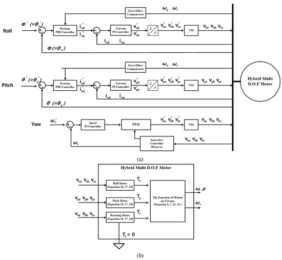
Figure 5.
Block diagrams for the simulation: (a) Block diagram of position control for the HMDOF motor; (b) Block diagram of the HMDOF motor.
The block diagram of the HMDOF motor is shown in Figure 5b, wherein the equations for the modeling of the motor is shown. In this simulation, the mathematical model, HMDOF, is developed with the equations in Section 3 and the parameters in Table 3.
Table 3.
Specifications for tilting motor.
Table 3 shows the specifications of tilting motor for this simulation. The DC-link voltage for controlling the tilting motors was 20 V, considering the maximum voltage of the motor in Table 1 and the phase current was limited to 3 A. Moreover, the operating angle range was limited to ±15, and it is reduced for considering the motion of the manufactured motor. The resistance, inductance, and PM linkage flux are noted in Table 3, and they are applied for the modeling of tilting motors and the control algorithm.
The inputs of the position controller of the tilting motors in Figure 5a were the command angle of the motor and the feedback measured by the resolver. The outputs of the controller were the d–q axis currents of the tilting motors, calculated using the PID controller. The gains of the PID controller were set as follows: Kp = 10, Ki = 10, and Kd = 5, respectively. It is common to implement the speed controller after the position controller; however, in an HMDOF motor, the speed controller is omitted because the operating range is small. The output of the position controller is set to the command of the q-axis current controller, which is proportional to the motor torque. Finally, the sampling frequency of the position controller is set to 1 kHz.
The current controllers in Figure 5a were developed to independently control the d- and q-axes. The feedback of the d–q-axis currents was converted from the measured three-phase currents of the motor. Meanwhile, the command of the d-axis current was set to zero because the tilting motors were not driven in the field-weakening control for high-speed operation. Therefore, only the q-axis current command was proportional to the output of the position controller. Although each current controller included a PI controller, the q-axis current controller has a feed-forward compensator to compensate for the gyroscopic effect. The gains of the PI current controller were set as Kp = 10 and Ki = 5, and the feed-forward gain was set to 20.
The block diagram of the HMDOF motor in Figure 5b was developed according to the motion and voltage equations described in Section 3. The equations for modeling the motor are from Equations (16)–(18). From these equations, the d–q axis voltages and currents can be calculated and the motor torque is also calculated with parameters in Table 3. Additionally, the motion of the HMDOF motor is developed from Equations (3), (7), (11), and (12). The tilting angles are calculated from the equation of motion with the torque. Referring to the experimental setup in Section 4.2, the HMDOF is fixed on the ground. Therefore, there is no motion in yaw direction of the entire HMDOF, and it is described as in Figure 5b. However, the rotating torque only for rotating motor is noted as . As shown in Figure 5a, the tilting and rotating motors were independently controlled for the desired torque, speed, and position. The simulation in Figure 5 shows the results of the position control of the tilting motors when the speed of the rotating motor () was 1000 RPM. Additionally, position control was simulated when the roll angle command () was zero and the pitch angle command () was changed from 0° to 5°.
Figure 6 shows the results of the position control. It includes the angle commands and feedback in the roll and pitch directions and the q-axis current commands and feedback of the tilting motors. In Figure 6a,b, and denote the q-axis currents of the roll and pitch motors, respectively, and and denote the roll and pitch angles, respectively. Figure 6c shows the trajectory of the tilting motors on the plane. As shown in Figure 6a,b, the position command of the pitch motor is changed, but the position command of the roll motor maintains zero; however, the position feedback of the roll motor is notched by approximately 0.2° by the gyroscopic effect. The torque of the roll motor is generated to overcome the movement due to the gyroscopic effect, which can be confirmed by the command and feedback in Figure 6a. In addition, it shows that zero-degree control of the roll motor is well performed according to the test results. In particular, the q-axis maximum current of the roll motor was approximately 1.5 A (0.15 Nm). In Figure 6b, the q-axis current and angle results of the pitch motor are shown. The q-axis maximum current of the pitch motor was approximately 2.5 A (0.3 Nm). The maximum angle feedback of the pitch motor was 5.8° for a command of 5°, and the settling time of the pitch motor control was approximately 1.2 s.
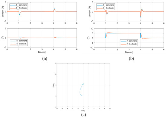
Figure 6.
Simulation results for the position control of the HMDOF motor at the rotating motor speed of 1000 RPM: (a) The control results of the roll motor; (b) The control results of the pitch motor; (c) The trajectory of the tilting motors on the plane.
The modeling and coordinate system settings of the HMDOF motor were confirmed through simulation results. Owing to the gyroscopic effect, the control results of the unidirectional motor affected the motion of the other motor. Therefore, the control algorithm of the manufactured motor was implemented by considering the torque of the gyroscopic effect. Additionally, the PID position controllers and the PI current controllers have been constructed in the simulation, and their control gains have been set up. The period and gains of the controllers for the experiments are implemented by referring to the simulation result.
4.2. Experimnets on the HMDOF Motor Control
This section describes the experimental results obtained using the manufactured HMDOF motor. As in the previous simulation, the results of the position control test of the tilting motors with the rotation of the rotating motor are shown in following figures; with Figure 7 showing the HMDOF motor and its experimental configuration. For tilting control, each direction of the inner structure had one SPMSM and one resolver, and the d-q vector control was performed with the position of the rotor measured by the resolver.
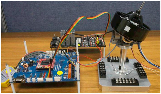
Figure 7.
The experiment configuration for the position control of the HMDOF motor.
As mentioned in Section 2, the rotating motor surrounding the inner structure was manufactured as a three-phase outer rotor-type BLDC motor and the stator of the rotating motor was fixed to the moving inner structure. Additionally, an inertial measurement unit (IMU) was implemented on the moving inner structure and used to measure the tilting angle of the HMDOF motor. The position angle commands of the tilting motors were calculated using the attitude angles of the HMDOF motor from the IMU data.
The motor control board for the experiment included Texas Instruments TMS320F28335. Three sets of three-phase inverters using an IGBT were implemented for the control experiments.
To set a test condition similar to that of the simulation, the DC link voltage for motor control was set to 20 V, and the maximum current value from the inverter was limited to 3 A. In addition, considering the mechanical interference of the moving inner structure, the operating angle range of the tilting motors was limited to ±15°. The control period and gains are set up by referring to the simulation.
Figure 8 and Figure 9 show the results of the position control when the speed of the rotating motor was 1120 RPM. As in the previous simulation, a feedforward compensator considering the gyroscopic effect was applied to the position controller. The PID control gains were set to be the same as those in the simulation. However, the gain of the feedforward compensator was set to 0 in Figure 8, and to 20 in Figure 9.
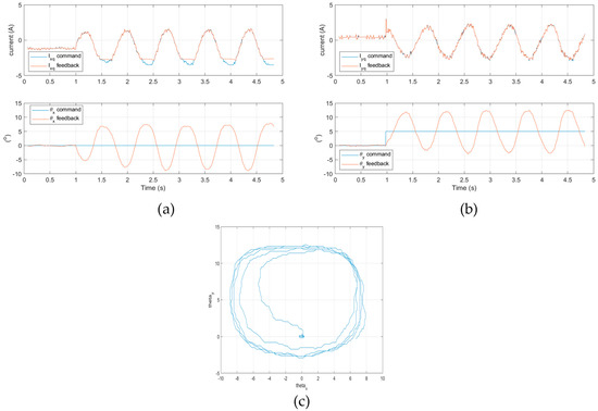
Figure 8.
The experiment results for the position control of the HMDOF motor at the rotating motor speed of 1120 RPM (without feedforward compensator): (a) the control results of the roll motor; (b) the control results of the pitch motor; (c) the trajectory of the tilting motors on the plane.
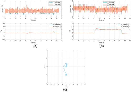
Figure 9.
The experiment results for the position control of the HMDOF motor at the rotating motor speed of 1120 RPM (with feedforward compensator): (a) the control results of the roll motor; (b) the control results of the pitch motor; (c) the trajectory of the tilting motors on the plane.
Position control was performed when the position command in the roll direction was set to 0° and the pitch angle command was changed to 0° ➔ 5° ➔ 0°. Figure 8 and Figure 9 show the q-axis current and the angle data of the roll and pitch motors, respectively.
In Figure 8 and Figure 9, and denote the q-axis currents of the roll and pitch motors, respectively, and θx and θy denote the roll and pitch angles, respectively. Figure 8c and Figure 9c show the trajectories of the tilting motors on the plane.
In Figure 9, the position control with the compensator performs better than the results in Figure 8. In Figure 9a,b, when the pitch axis command was changed, the q-axis current of the roll motor was notched by approximately 1.62 A. The tilt angle of the roll motor had an overshoot of 1.5°. The q-axis maximum current of the pitch motor was measured by 2.7 A. Moreover, the maximum angle of the pitch motor was measured to be about 6.8°, and the settling time was measured to be about 1.7 s. In Figure 9c, the trajectory of the HMDOF motor converges in a clockwise direction. We determined the similarity of the results between the simulation and the experiment. According to the simulation and experimental results, the gyroscopic effect occurs in the position control of the HMDOF, and the HMDOF motor modeling and control algorithm must consider this to control the desired position. Additionally, further research will be carried out to reduce the response time and improve the control algorithm based on these results.
Figure 10 shows the roll and pitch angles from the IMU data when a disturbance was intentionally injected. The disturbance is generated by randomly applying a weight load of approximately 100 g to the tilting motors while controlling their zero position for the tilting motors. According to the test results, it was determined that the position angle of the motor changed by at most 20° when the disturbance was applied, but the attitude angle of the HMDOF by the IMU data was maintained at less than 1°. Therefore, from this test result, it can be confirmed that precise control is performed even when a random disturbance is applied.
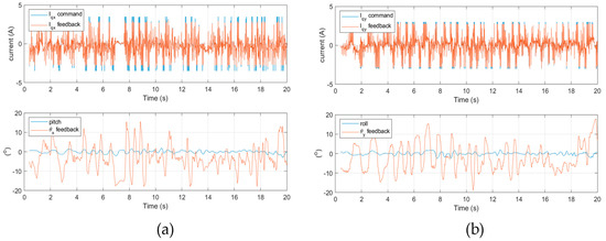
Figure 10.
The experiment results for the position control of the HMDOF motor with the disturbance: (a) the control results of the roll motor; (b) the control results of the pitch motor.
Figure 11 shows the results of verifying the position control performance at the rotating motor speed. For the test, the magnitude of the steady-state current and position angle of the tilting motors were measured at the speed of the rotating motor.
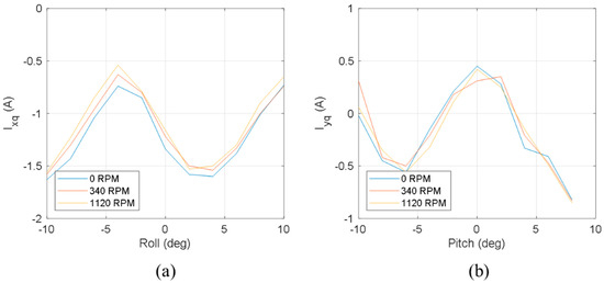
Figure 11.
Comparison of q-axis currents at the rotating speed and the tilting angle: (a) the control results of the roll motor; (b) the control results of the pitch motor.
Figure 11 shows the comparison result of the q-axis current of each motor at the position angle of the tilting motors while controlling the speed of the rotating motor to 0, 340, and 1120 RPM, respectively. From the results, it is observed that even if the speed of the rotating load were increased to 1120 RPM, the magnitude of the q-axis current flowing through the tilting motor during position control hardly differs. This implies that a similar torque for position control is required at different rotating speeds. However, owing to the cogging torque of the tilting motors, a difference in the current occurs, depending on the position angle. Moreover, as confirmed by the previous test results, the q-axis current is affected by the disturbance of the gyroscopic effect. Therefore, further research on optimizing the control algorithm should be conducted in the future to achieve faster and more precise response characteristics.
5. Conclusions
The HMDOF motor has both tilting motors and a rotating motor; therefore, it can be easily driven in multi-DOF. Loads of the HMDOF motor are divided into the weight of the motor and the speed of the rotating motor. The load weight is an important factor in the design of the motor size. However, the speed of the rotating motor affects the control performance of the motor. In this study, the performance of the motor was verified through simulations and experiments using an HMDOF motor with a specific speed of the rotating motor.
For the construction of mathematical models of the motor, the following were considered. First, the coordinate systems of the motor were defined along the tilting and rotating motions of the HMDOF motor. Second, the physical quantity of the motor was represented in each coordinate system. Finally, for the simulation, the torque equation was derived from the voltage equation of the motor, and the mathematical modeling of the motor was completed using the equation of motion and transformation matrices to a specific coordinate system. The HMDOF motor was simulated using mathematical modeling.
Position control tests were performed to verify the control performance of the manufactured HMDOF motor. The position control of the tilting motor was performed when the rotating motor was rotating at a specific speed. In the position control algorithm, the disturbance caused by the gyroscopic effect was considered for precision control, and the position control performance of the HMDOF motor was verified by controlling the tilting motor to the desired position. Moreover, the robustness of the control against disturbances applied to the motor was verified. Finally, the steady-state characteristics of the tilting motor were verified based on the speed of the rotating motor.
From the results of this study, it was confirmed that the HMDOF motor can be used in fields that require tilting control with rotating loads, particularly in drones with one or more rotors. In future studies, it will be possible to expand the range of utilization of multi-DOF motors, such as optimization of the size of the motor and improvement of the control algorithm for a fast response.
Author Contributions
Conceptualization, H.-J.P.; methodology, H.-J.P.; software, H.-J.P.; validation, H.-J.P., S.-C.G.; formal analysis, H.-J.P.; investigation, H.-J.P.; resources, H.-J.P.; data curation, H.-J.P.; writing—original draft preparation, H.-J.P.; writing—review and editing, H.-J.P., S.-C.G.; visualization, H.-J.P.; supervision, S.-C.G.; project administration, S.-C.G.; funding acquisition, S.-C.G. All authors have read and agreed to the published version of the manuscript.
Funding
This work was supported by the National Research Foundation of Korea (NRF) grant funded by the Korea government (MSIT) (No. 2020R1C1C1011001).
Institutional Review Board Statement
Not applicable.
Informed Consent Statement
Not applicable.
Data Availability Statement
The data presented in this study are available on request from the corresponding author. The data are not publicly available due to ongoing studies.
Conflicts of Interest
The authors declare no conflict of interest.
References
- Xia, K.; Xing, H.; Ding, L.; Gao, H.; Liu, G.; Deng, Z. Virtual decomposition based modeling for multi-DOF manipulator with flexible joint. IEEE Access 2019, 7, 91582–91592. [Google Scholar] [CrossRef]
- Cheng, J.; Bi, S.; Yuan, C.; Cai, Y.; Yao, Y.; Zhang, L. Dynamic Modeling Method of Multibody System of 6-DOF Robot Based on Screw Theory. Machines 2022, 10, 499. [Google Scholar] [CrossRef]
- Lee, D.G.; Seo, T.W. Lightweight multi-DOF manipulator with wire-driven gravity compensation mechanism. IEEE/ASME Trans. Mech. 2017, 22, 1308–1314. [Google Scholar] [CrossRef]
- Ryll, M.; Bülthoff, H.H.; Giordano, P.R. A novel overactuated quadrotor unmanned aerial vehicle: Modeling, control, and experimental validation. IEEE Trans. Control Syst. Technol. 2015, 23, 540–556. [Google Scholar] [CrossRef]
- Zheng, P.; Tan, X.; Kocer, B.B.; Yang, E.; Kovac, M. TiltDrone: A Fully-Actuated Tilting Quadrotor Platform. IEEE Robot. Autom. Lett. 2020, 5, 6845–6852. [Google Scholar] [CrossRef]
- Zhong, G.; Cao, J.; Chai, X.; Bai, Y. Design and Performance Analysis of a Triphibious Robot with Tilting-Rotor Structure. IEEE Access 2021, 9, 10871–10879. [Google Scholar] [CrossRef]
- Arakawa, A.; Hasegawa, T.; Watanabe, K.; Nagai, I. Control of Attitude Angle for a Tilted Quadrotor. In Proceedings of the 2018 IEEE International Conference on Mechatronics and Automation, Jilin, China, 5–8 August 2018. [Google Scholar]
- Elfeky, M.; Elshafei, M.; Saif, A.W.A.; Al-Malki, M.F. Quadrotor helicopter with tilting rotors: Modeling and simulation. In Proceedings of the 2013 World Congress on Computer and Information Technology, Sousse, Tunisia, 22–24 June 2013. [Google Scholar]
- Ahmed, A.M.; Katupitiya, J. Modeling and Control of a Novel Vectored-Thrust Quadcopter. J. Guid. Control Dyn. 2021, 44, 1399–1409. [Google Scholar] [CrossRef]
- Park, H.J.; Lee, H.J.; Cho, S.Y.; Ahn, H.W.; Lee, K.D.; Park, C.Y.; Won, S.H.; Lee, J. A Performance study on a permanent magnet spherical motor. IEEE Trans. Magn. 2013, 49, 2307–2310. [Google Scholar] [CrossRef]
- Jinjun, G.; Kim, D.H.; Son, H. Effects of Magnetic Pole Design on Orientation Torque for a Spherical Motor. IEEE/ASME Trans. Mech. 2013, 18, 1420–1425. [Google Scholar] [CrossRef]
- Li, Z. Robust Control of PM Spherical Stepper Motor Based on Neural Networks. IEEE Trans. Ind. Elec. 2009, 56, 2945–2954. [Google Scholar]
- Dehez, B.; Galary, G.; Grenier, D.; Raucent, B. Development of a spherical induction motor with two degrees of freedom. IEEE Trans. Magn. 2006, 42, 2077–2089. [Google Scholar] [CrossRef]
- Leve, F.A. Evaluation of Steering Algorithm Optimality for Single-Gimbal Control Moment Gyroscopes. IEEE Trans. Cont. Syst. Tech. 2014, 22, 1130–1134. [Google Scholar] [CrossRef]
- Sakaidani, Y.; Hirata, K.; Niguchi, N.; Maeda, S. Experimental verification of feedback control of a 2-DOF spherical actuator. IEEE Trans. Magn. 2014, 50, 8204404. [Google Scholar] [CrossRef]
- Lee, H.J.; Liu, H.C.; Lee, J.J.; Lee, J.; Jung, D.H. Hybrid Multi-DOF Motor for Multi-Copter Unmanned Aerial Vehicle. IEEE Trans. Mag. 2019, 55. [Google Scholar] [CrossRef]
- Lee, H.J.; Ahn, H.W.; Lee, J.K.; Lee, J.; Won, S.H. Newly proposed hybrid type mutli-DOF operation motor for multi-copter UAV systems. In Proceedings of the 2015 IEEE Energy Conversion Congress and Exposition, Montreal, QC, Canada, 20–24 September 2015. [Google Scholar]
- Hong, H.S.; Won, S.H.; Lee, H.W.; Bae, J.N.; Lee, J. Design of Torque Actuator in Hybrid Multi-DOF System Considering Magnetic Saturation. IEEE Trans. Magn. 2015, 51. [Google Scholar] [CrossRef]
- Jang, G.H.; Kim, M.G. Optimal Commutation of a BLDC Motor by Utilizing the Symmetric Terminal Voltage. IEEE Trans. Magn. 2006, 42, 3473–3475. [Google Scholar] [CrossRef]
- Zhang, H.; Liu, G.; Zhou, X.; Zheng, S. High-Precision Sensorless Optimal Commutation Deviation Correction Strategy of BLDC Motor with Asymmetric Back EMF. IEEE Trans. Ind. Inform. 2021, 17, 5250–5259. [Google Scholar] [CrossRef]
- Yao, X.; Zhao, J.; Lu, G.; Lin, H.; Wang, J. Commutation error compensation strategy for sensorless brushless DC motors. Energies 2019, 12, 203. [Google Scholar] [CrossRef]
- Giernacki, W.; Gośliński, J.; Goślińska, J.; Espinoza-Fraire, T.; Rao, J. Mathematical modeling of the coaxial quadrotor dynamics for its attitude and altitude control. Energies 2021, 14, 1232. [Google Scholar] [CrossRef]
- Lyu, P.; Lai, J.; Liu, J.; Zhang, Q. A Thrust Model Aided Fault Diagnosis Method for the Altitude Estimation of a Quadrotor. IEEE Trans. Aerosp. Electron. Syst. 2018, 54, 1008–1019. [Google Scholar] [CrossRef]
- Azid, S.I.; Kumar, K.; Cirrincione, M.; Fagiolini, A. Robust motion control of nonlinear quadrotor model with wind disturbance observer. IEEE Access 2021, 9, 149164–149175. [Google Scholar] [CrossRef]
- Singh, K.; Mehndiratta, M.; Feroskhan, M. QuadPlus: Design, Modeling, and Receding-Horizon-Based Control of a Hyperdynamic Quadrotor. IEEE Trans. Aerosp. Electron. Syst. 2022, 58, 1766–1779. [Google Scholar] [CrossRef]
- Wu, Y.; Hu, K.; Sun, X. Modeling and control design for quadrotors: A controlled hamiltonian systems approach. IEEE Trans. Veh. Technol. 2018, 67, 11365–11376. [Google Scholar] [CrossRef]


Publisher’s Note: MDPI stays neutral with regard to jurisdictional claims in published maps and institutional affiliations. |
© 2022 by the authors. Licensee MDPI, Basel, Switzerland. This article is an open access article distributed under the terms and conditions of the Creative Commons Attribution (CC BY) license (https://creativecommons.org/licenses/by/4.0/).