Article

An LBM-Based Investigation on the Mixing Mechanism of Double Rows Film Cooling with the Combination of Forward and Backward Jets

1
College of Mechanical and Electrical Engineering, Hohai University, No. 1 Xikang Road, Nanjing 210098, China
2
State Key Laboratory for Strength and Vibration of Mechanical Structures, Xi’an Jiaotong University, No. 28 Xianning West Road, Xi’an 710049, China
*
Author to whom correspondence should be addressed.
Energies 2022, 15(13), 4848; https://doi.org/10.3390/en15134848
Submission received: 30 April 2022 / Revised: 23 June 2022 / Accepted: 28 June 2022 / Published: 1 July 2022

Abstract

:
Film cooling has been widely applied to the highly efficient thermal protection of gas turbines. By using the simplified thermal lattice Boltzmann method (STLBM), a series of large-scale simulations of film cooling are performed to dig up the mixing mechanism of double rows film cooling with the combination of forward and backward jets at the first attempt. The combination of an upstream row with forward jet and a downstream row with backward jet is considered. The Reynolds number is 4000. The blowing ratio of the upstream coolant jet is fixed as B R 1 = 0.5 . For the downstream coolant jet ( B R 2 ), five values ranging from 0.2–0.8 are considered. The inclination angles of forward jet and backward jet are 35° and 145°, respectively. The numerical results reveal that the performance of film cooling is greatly improved by backward downstream jet due to the suppression of counterrotating vortex pair (CVP). Moreover, the flow structure is changed with the blowing ratio of backward jet. An anti-CVP having the opposite rotational direction to CVP appears as the blowing ratio of backward jet is large. The special flow structure weakens the adverse effect of CVP and transports much coolant jet to the cooled wall. Correspondingly, the time-averaged film cooling effectiveness is increased and the fluctuation of film cooling effectiveness is decreased. All of these indicate that a backward downstream jet with a large blowing ratio improves film cooling performance. The results obtained in this work help to the optimization of film cooling scheme, which also benefit the promotion and application of STLBM in gas turbine engineering.

1. Introduction

Film cooling is one of the most widely used technology in gas turbine engine for cooling of high-temperature components [1,2]. In the film cooling process, coolant jet flow is introduced into hot crossflow through discrete holes drilled on the surface of high-temperature components of gas turbine and forms a coolant-film layer. The flow process of film cooling can be regarded as a basic configuration of jet in crossflow (JICF), which is firstly investigated by Kamotani and Greber [3]. The results showed that the counterrotating vortex pair (CVP) consisting of left and right vortex with opposite rotating direction was formed in the downstream because of the mixing between crossflow and jets. Due to the similarity in shape, it is popularly known as the kidney vortex. CVP is an important flow structure affecting the performance of film cooling significantly. The studies of Leylek et al. [4,5,6,7] pointed out that the appearance of CVP would lift the coolant jet from the wall surface and enhance the mixing of hot crossflow with coolant jet, having an undesirable effect on film cooling performance. Hence, CVP must be minimized or eliminated to maintain maximum coolant-film coverage of the cooled surface and improve the performance of film cooling.
In order to suppress the generation of CVP and weaken the associated undesirable effects, many kinds of active and passive control [8,9,10,11,12,13,14,15,16,17,18] have been proposed. Among the active control methods, the key parameters mainly include jet flow frequency [8,9], intensity of freestream turbulence [10,11], density ratio [11,12], and blowing ratio [13]. As for passive control, geometrical shape of film cooling hole [14,15,16] and geometrical parameters of upstream obstacle [17,18] receive lots of attention. The results indicate that the application of a shaped hole or upstream obstacle can suppress the generation of CVP, and hence, weaken the lift-off of coolant jet and its undesirable effect on film cooling performance. However, it also increases the complexity and cost of the cooling system by using a shaped hole or upstream obstacle, which is not a good choice for the optimal design of film cooling.
In the quest of decreasing the intensity of CVP and lift-off of coolant jet, while at the same time solving the design difficulties, many researchers have given insights into the application of backward injection in film cooling. Li [19] conducted a numerical study on film cooling with backward injection to explore its detailed flow structure and heat transfer behavior. It was found that the film cooling hole with backward injection provides higher film cooling effectiveness in the spanwise direction, by comparing with film cooling hole with forward injection. An experimental investigation on film cooling of a flat surface with forward and backward injection was carried out by Park et al. [20]. The results indicated that at a high blowing ratio, the enhancement and uniform distribution of film cooling effectiveness were produced by cylindrical holes with backward injection. Then, Singh et al. [21] performed the experimental and numerical study of film cooling on a flat plate with forward and backward injection. The inclination angle of the film cooling hole was varied from 30 ° to 60 ° in both forward and backward directions at five blowing ratios ranging from 0.25 to 3.0. It was found that film cooling effectiveness obtained with backward holes was much higher than that of forward holes, and the film cooling effectiveness with backward injection was less sensitive to the inclination angle of film cooling hole. Zhao et al. [22] numerically investigated the effect of cylindrical hole, expansion-shaped hole and fan-shaped hole with forward and backward injection on film cooling effectiveness. The results showed that the uniformity of film cooling effectiveness obtained by backward hole was higher than that of the hole with forward injection.
The improvement of the film cooling hole with backward injection is quite considerable, especially at a high blowing ratio. However, it should be noted that the streamwise coverage of the coolant-film layer obtained by backward jet is smaller than that of forward jet. A configuration composed of forward injection holes in one row and backward injection holes in another row may tackle this problem, and hence, becomes one of the research hotspots. However, its mixing mechanism is rarely considered. The performance of multi-row film cooling is dominated by the mixture of the coolant jets ejected from different rows, which is affected significantly by the interaction between hot crossflow and coolant jets. Thus, in order to design efficient film cooling scheme, better understandings of the interaction between crossflow and jets with forward and backward injection are in urgent demand.
The current work focuses on the interaction between crossflow and jets ejected from two rows with forward and backward injection, which can fill the gap in the understanding of multi-rows film cooling with the combination of forward and backward jets. A better understanding of the interaction between crossflow and jets with forward and backward injection would be conductive to the development of efficient film cooling schemes. It also has great significance for energy-saving.
It should be noted that film cooling is a three-dimensional turbulent flow and heat transfer process. There are a large number of coherent structures with various scales arising due to mixing between hot crossflow and coolant jets. The mixing mechanism of film cooling is extremely complicated and influenced by numerous factors. Therefore, the further understanding of the film-cooling mixing mechanism is extremely challenging. For numerical simulation, it is necessary to capture the instantaneous coherent structures with various scales and their interactions accurately. Capturing the instantaneous flow dynamics in turbulence simulation is a great challenge for computational methods and tools. An efficient and accurate computational method is urgently needed. Nowadays, most of the turbulence simulations of film cooling are conducted by using time-averaged method RANS. However, the research results indicate that the turbulence model based on RANS cannot calculate film cooling effectiveness accurately, while large eddy simulation (LES) can accurately predict film cooling effectiveness [23]. This is because that LES can accurately capture large-scale coherent structure which dominates the turbulent mixing. However, heavy computation load and long-time consumption are the bottleneck for LES. Duggleby et al. [24] performed a blind LES of film cooling with about 88.7 million meshes and obtained accurate results. Although a massively parallel solver was used, it took about two months to accomplish the simulation. This is principally because that the simulation is performed by solving the Navier–Stokes (N-S) equation. The N-S equation is a group of highly non-linear differential equations, whose solution is extremely difficult and parallelism is not very good. Therefore, the LES based on the N-S equation is time-consuming. The long computing period is not conductive to the optimized design of film cooling.
In order to tackle this issue, this work tries to dig up the mixing mechanism of film cooling with LES based on the lattice Boltzmann method (LBM). LBM is a kind of mesoscopic method, which shows the advantages of easy implementation of boundary conditions, simple programming, and fully parallel algorithms [25]. Significantly, the fully parallel algorithm of LBM makes it match perfectly with GPU, which greatly improves the computational efficiency. Therefore, the large-scale simulation based on LBM-GPU has the considerable potential to fulfill detailed turbulence investigation. However, to our knowledge, there are few numerical investigations on film cooling using LBM and GPU. This paper is a pioneer of the film-cooling investigation based on LBM-GPU. There is so much to explore. Although LBM is one of the ideal alternative methods for high-performance simulation and prevalent in the field of computational fluid dynamics (CFD), the numerical stability and accuracy still need to be improved. On the other hand, the large cost of virtual memory blocks the further application of LBM to high-performance simulation. In this paper, simplified thermal lattice Boltzmann method (STLBM) coupled with Smagorinsky subgrid-scale stress (SGS) model of LES is adopted to conduct the simulation on film cooling. STLBM is the extension of LBM directly updating the macroscopic variables without storing the distribution functions during the computational process. It can greatly lower the virtual memory cost, which can fulfill larger scale simulation with limited hardware resources. This is of great benefit to the further understanding of mixing mechanism in film cooling process. Moreover, STLBM shows nice performance in terms of numerical stability, and has been analytically proven to be unconditionally stable [26].
The influence of the backward downstream jet with various blowing ratios on the flow structure and heat-transfer features is mainly investigated in this paper. The film cooling holes are arranged in line because the in-line arrangement shows more significant interaction than that of staggered arrangement, which is conducive to obtain better understanding of the mixing mechanism. Moreover, the combination of an upstream row of forward-holes and a downstream row of backward-holes is the primary focus of current work. The paper is organized as follows: numerical methods (Section 2), results and discussion (Section 3), and conclusions (Section 4). In Section 2, a brief introduction of flow configuration for double rows film cooling with the combination of forward and backward jets is given, and the STLBM and LES-SGS model are provided. The flow field and heat transfer features resulted from the interaction between crossflow and jets from two rows with forward and backward injections are analyzed after the validation of the LES model and the grid sensitivity study of the simulation are performed in Section 3. Moreover, how the flow field and heat transfer features are influenced by blowing ratio of backward downstream coolant jets is studied. Finally, this paper gives recommendations for future studies on the basis of the conclusion in Section 4.

2. Numerical Methods

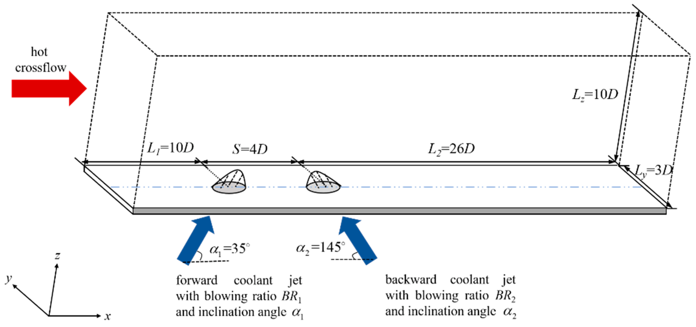
2.1. Computational Domain and Boundary Conditions

The flow configuration for double rows film cooling with the combination of forward and backward jets is shown in Figure 1, which includes a mainstream channel and two rows of film cooling holes. Seen from Figure 1, the upstream and downstream coolant jets inject into the mainstream channel through circular film cooling hole with forward and backward injection, respectively. The size of mainstream channel is 40 D × 30 D × 10 D in x-, y-, and z-directions. The upstream film cooling hole locates at the site L 1 = 10 D far from the mainstream inlet and the distance between the upstream and downstream holes is S = 4.0 D . Here, the original, the point with coordinates (0, 0, 0), is set at the center of upstream film cooling hole.   D is the diameter of film cooling hole. Blowing ratio is defined as B R = ρ j u j / ρ u . ρ j and ρ are the density of coolant jet and cross flow, respectively. u j and u are the velocity of coolant jet and crossflow, respectively. The blowing ratio of upstream coolant jet is fixed and set as B R 1 = 0.5 . As for the downstream coolant jet ( B R 2 ), five values of 0.2, 0.35, 0.5, 0.65, and 0.8 are taken into consideration. Table 1 illustrates the parameters list of simulation cases. There are six cases with different parameters of the inclination angle and blowing ratio being examined. To demonstrate the effect of the backward downstream coolant jet on film cooling characteristics, the case of double rows film cooling with forward injection holes (Case 1) is conducted to serve as a baseline issue. In Case 1, the double rows film cooling with a 35 ° forward injection and blowing ratio of 0.5 is carried out. For comparison, the double rows film cooling with a 35 ° upstream forward injection ( α 1 = 35 ° ) and a 35 ° downstream backward injection ( α 2 = 145 ° ), and the same combination of the blowing ratio ( B R 1 = B R 2 = 0.5 ) is set as Case 2. Moreover, to investigate the effect of blowing ratio of backward downstream jet ( B R 2 ), the differences among Cases 2–6 are in the blowing ratio of the backward downstream jet.
Except for the inclination angle and blowing ratio shown in Table 1, the Reynolds number based on crossflow velocity u and diameter of film cooling hole D is set as R e = ρ u D / ν = 4000 . The density of crossflow ρ is assumed to be the same as that of jet flow ρ j . The temperature ratio T j / T is set to 0.5. T and T j represent the hot crossflow temperature and coolant jet temperature, respectively. To evaluate the performance of film cooling, this work mainly focuses on the non-dimensional temperature θ = T a w T j / T T j and adiabatic film cooling effectiveness η = T T a w / T T j . Here, T a w is the temperature of the adiabatic bottom wall.
The computational boundary conditions are set as follows. For the inlet velocity boundary condition of the mainstream flow, a 1 / 7 power law velocity profile is adopted. The turbulent boundary layer thickness δ is assumed to be 2.0 D , and the crossflow velocity u is set as 25 m/s. The mass flow rate is fixed at the inlet of film cooling hole to ensure the corresponding value of blowing ratio. For the outlet boundary condition of mainstream flow, an atmospheric pressure is specified. Periodic boundaries are applied in a spanwise direction. As for the bottom wall, it is assumed to be adiabatic and non-slip. On the other hand, the calculation stops as the error is less than 10−6. The error formula used in the current work is shown as follows:
u u 0 2 + v v 0 2 + w w 0 2 < 10 6
where u , v , and w are the streamwise, spanwise, and wall-normal velocity of the present time-step, respectively, and u 0 , v 0 , and w 0 are the streamwise, spanwise, and wall-normal velocity of last time-step, respectively.

2.2. Solution Algorithm

In this work, STLBM coupled with the LES-SGS model is adopted to conduct the simulation on film cooling.

2.2.1. Simplified Thermal Lattice Boltzmann Method

The governing equation used in this paper is the lattice Boltzmann equation (LBE), which is shown below:
f i x + e i Δ t , t + Δ t f i x + e i Δ t , t + Δ t = Ω i f
g i x + e i Δ t , t + Δ t g i x + e i Δ t , t + Δ t = Ω i g
where f i and g i are the density distribution function and the internal energy distribution function along the i direction, respectively, e i is the discrete velocity, Δ t is the time-step, and Ω i is the collision term. Based on the BGK model applied in this paper, the collision terms are shown as follows:
Ω i f = 1 τ f f i f i e q
Ω i g = 1 τ g g i g i e q
where f i e q and g i e q are, respectively, the equilibrium density distribution function and the equilibrium internal energy distribution function along the i direction and τ f and τ g represent relaxation factors related to kinematic viscosity ν and thermal diffusivity α, respectively.
According to the basic formulation of STLBM shown in [26], the density ρ , velocity u , and temperature T of discrete particle can be calculated by the following two steps:
Predictor step:
ρ x , t = i f i e q x e i Δ t , t Δ t
ρ x , t u x , t = i e i f i e q x e i Δ t , t Δ t
T x , t = i g i e q x e i Δ t , t Δ t
Corrector step:
ρ x , t = ρ x , t
ρ x , t u x , t = ρ x , t u x , t + 1 1 τ f i e i f i n e q x e i Δ t , t + F E x , t Δ t
T x , t = T x , t + 1 1 τ g i g i n e q x e i Δ t , t
where the superscript * represents the intermediate value. The approximation of non-equilibrium distribution functions f i n e q and g i n e q is shown as follows [26]:
f i n e q x , t = τ f f i e q x , t f i e q x e i Δ t , t Δ t
g i n e q x , t = τ f g i e q x , t g i e q x e i Δ t , t Δ t
It should be noted that the equilibrium distribution functions f i e q and g i e q are calculated from the intermediate density ρ , velocity u , and temperature T obtained in the predictor step by according to the discrete velocity set used in the simulation. In this work, the D3Q19 discrete velocity set shown in Figure 2 is adopted to perform the simulation of flow and temperature field. According to the D3Q19 discrete velocity set, the equilibrium distribution functions are defined below:
f i e q x , t = ω i ρ 1 + e i · u c s 2 + e i · u 2 2 c s 4 u 2 2 c s 2
g i e q x , t = ω i T 1 + e i · u c s 2 + e i · u 2 2 c s 4 u 2 2 c s 2
Besides, according to the Boussinesq approximation [27], the external force term can be regarded as a buoyance force related to the temperature:
F E x , t = 0 ρ g β T x , t T 0 x , t
where g is the gravitational acceleration, β is the thermal expansion coefficient, and T 0 is the reference temperature.
In our preliminary works [28,29,30], the hybrid thermal lattice Boltzmann method (HTLBM) is applied to perform the film-cooling simulation. The multiple-relaxation-time (MRT) model was used to improve the numerical stability of the conventional single-relaxation-time (SRT) model, although the MRT model requires more complex calculation. One point worth emphasizing is that STLBM used in this work is proven to be unconditionally stable. Therefore, the SRT model is applied in this work to promote the computational efficiency.

2.2.2. Smagorinsky Subgrid-Scale Stress Model

To capture the details of turbulence shown in film cooling performance with the limited computational hardware, the LES method is applied. Among many computational models of the LES method, the SGS model, which was introduced to LBM by Hou et al. [30], is used. In the LES-SGS model, the molecular viscosity ν 0 is replaced by effective viscosity ν e f f to consider the comprehensive effect of molecular ν 0 and eddy viscosity ν t , and their relationship is shown below:
ν e f f = ν 0 + ν t = ν 0 + C S Δ 2 2 α , β S ¯ α β S ¯ α β
where Δ represents the filter length scale and S ¯ α β = β u ¯ α + α u ¯ β / 2 is the filtered strain rater tensor [31]. Note that the value of Smagorinsky constant C S is set as 0.13 by referring to our previous work [32]. Based on the opinion of Bardina et al. [33], the filter length scale used in LES-SGS model is chosen as the lattice spacing Δ = Δ x = 1 .
Analogously, the effect thermal diffusivity can be calculated by:
α e f f = α 0 + α t
The turbulent thermal diffusivity α t is related to the turbulent Prandtl number:
P r t = ν t α t
where the value of P r t is set to P r t = 0.87 by assuming that the fluid is an ideal gas [34].

3. Results and Discussion

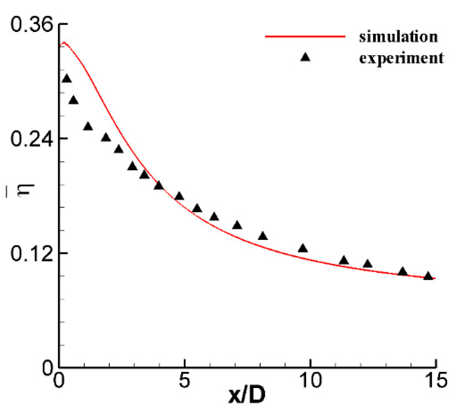
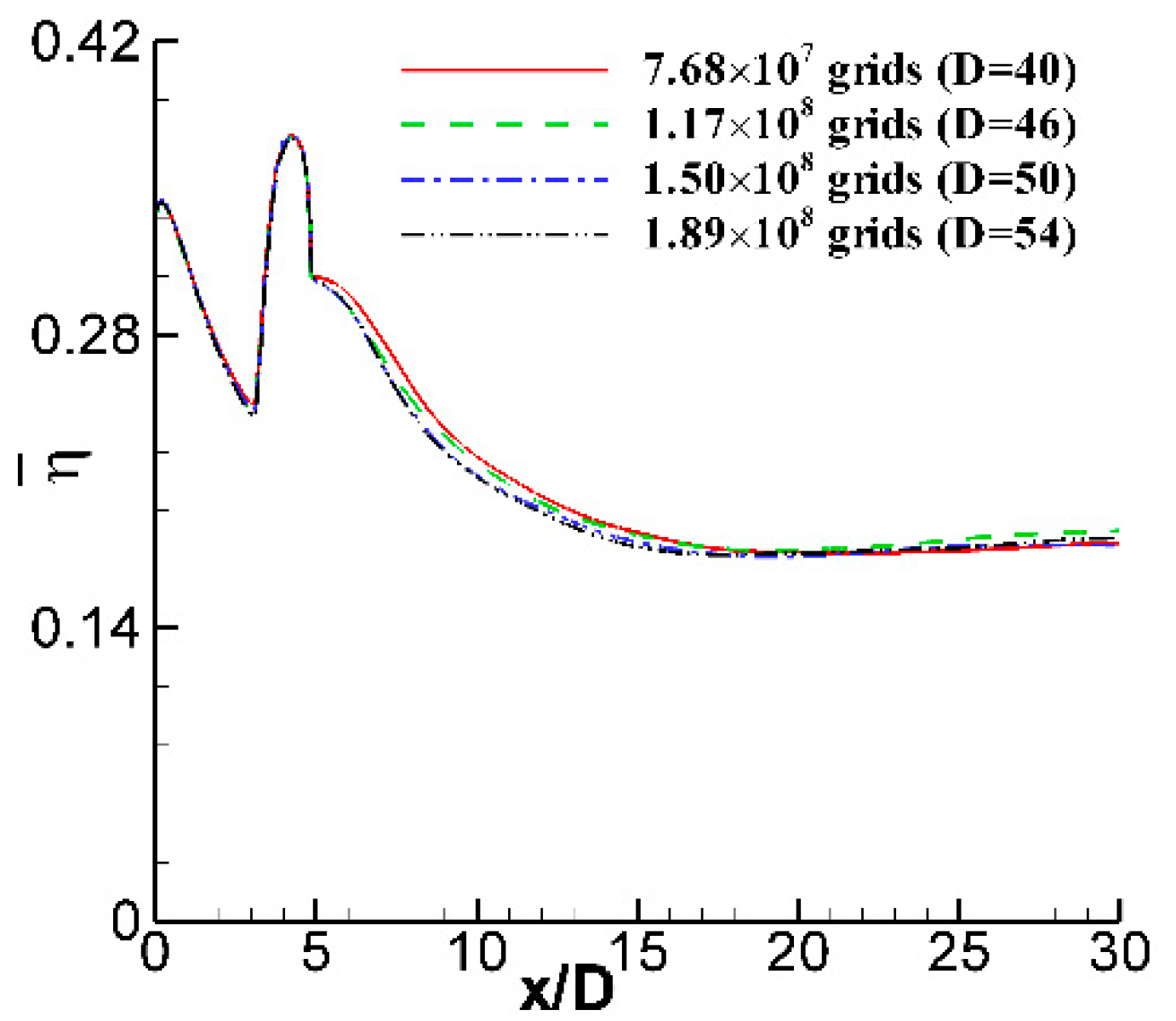
3.1. Validation of the Numerical Method and Grid Sensitivity Study

In this section, the validation of the numerical method is conducted before being adapted in the following simulations. The in-house STLBM-LES-GPUs code is validated by comparing the time-averaged temperature field with the experimental data of film cooling with cylindrical holes obtained by Chen et al. [35]. The numerical results of spanwise-averaged film cooling effectiveness with blowing ratio of 0.3 and inclination angle of 30 ° have been compared with the experimental data, which is shown in Figure 3. It should be noted that all the computational boundary conditions of the numerical simulation are set according to the experimental setup, except a slight difference in the inlet velocity boundary of coolant jet. In the simulation, the coolant is ejected from a delivery tube with 7.5 D length, while in the experiment, the coolant is supplied from a plenum with a hole length of 7.5 D . It can be seen from Figure 3 that the numerical results obtained with the in-house code are in good agreement with the experimental data, except for the region just at the trailing edge of the film cooling hole ( x / D 3.0 ). The mixing of the coolant jet with hot crossflow in this region is extremely intense and impacted significantly by the velocity distribution of the coolant jet. The difference of the boundary condition of the coolant jet would result in a discrepancy of the coolant jet velocity distribution [36]. Therefore, the authors believe that the deviations of spanwise-averaged film cooling effectiveness shown in the region downstream the trailing edge of film cooling hole mainly results from the difference of the boundary condition of the coolant jet. Meanwhile, to quantitatively compare the numerical and experimental results, the root-mean-square ( R 2 ) is employed to determine the error between them. R 2 is defined as follows:
R 2 = 1 i = 1 n a i b i 2 i = 1 n b i 2
where a i and b i represent the experimental and numerical value, respectively, n is the number of output data, and the R 2 value for spanwise-averaged film cooling effectiveness between the experimental and numerical results is 0.9926. Moreover, the relative error is less than 18%, which is acceptable for revealing the real turbine system. All of these indicate that the numerical method used in this work could well predict film-cooling characteristics.
Then, a grid sensitivity study is performed to make sure that all the results of current work are independent with the size of numerical grid. Figure 4 illustrates the results of Case 2 for four grid systems. In the four grid systems, 40, 46, 50, and 54 grids are respectively arranged for the length of 1.0 D . Since the uniform grid system is used, the total grid number of the four grid systems are 7.68 × 10 7 , 1.17 × 10 8 , 1.50 × 10 8 , and 1.89 × 10 8 , respectively. In the current work, two pieces of NVIDA Tesla P100 GPGPUs are applied to perform the simulation based on the CUDA 6.5 platform. With the grid number increasing from 7.68 × 10 7 to 1.89 × 10 8 grid nodes, the computational time ranges from 16 to 20 h when a certain evolution time-step of 1.50 × 10 4 is reached. It shows one of the advantages of LBM-GPUs in film-cooling investigation by achieving large-scale numerical simulation with low time-consumption. The results shown in Figure 4 indicate that when the grid number reaches to 50 of 1.0 D length, the influence of grid numbers on the simulation results can be ignored. Meanwhile, in order to meet the grid requirement of LES best, that is the mesh near the bottom wall satisfies to z + < 1 , 54 grids are arranged for the length of 1.0 D in all the simulations of the current work.

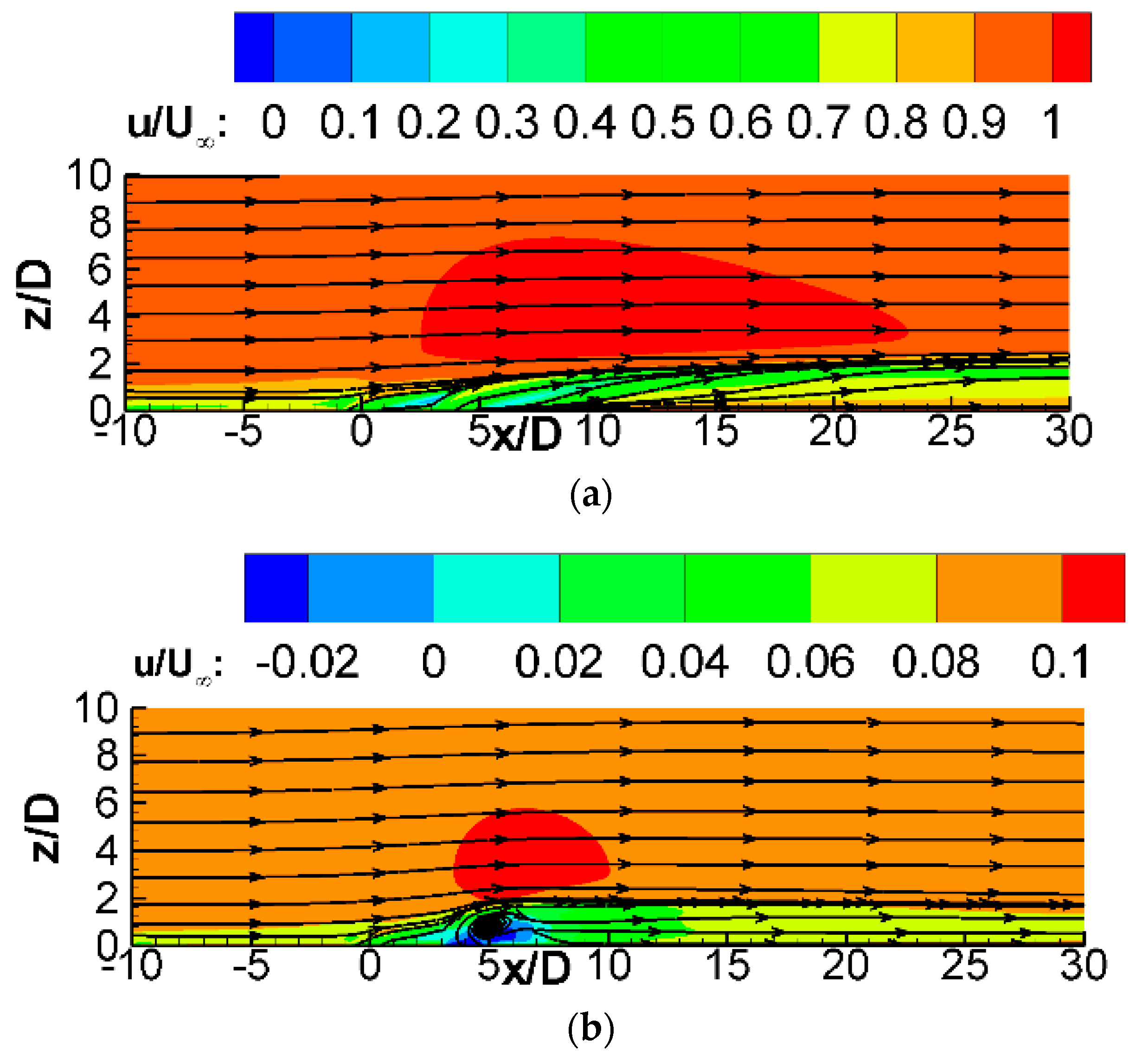
3.2. The Interaction between Crossflow and Double Rows Coolant Jets with Different Jet Orientations

In order to explore the effect of jet orientation on the interaction between crossflow and coolant jets ejected from upstream and downstream rows, the flow and heat-transfer features of double rows film cooling with forward (Case 1) and backward (Case 2) downstream jets are studied in this part.
Figure 5 shows the comparison of x-velocity profiles at (a) x / D = 2.0 and (b) x / D = 2.0 on the mid-span plane of Case 1 and Case 2. The x-velocity profiles at x / D = 2.0 and x / D = 2.0 on the mid-span plane can be regarded as the incoming boundary layers for the upstream and downstream film cooing hole, respectively. There is an inflection point can be clearly recognized both in the velocity profiles of x / D = 2.0 and x / D = 2.0 . According to the study of Wang et al. [37], the inflection point can be regarded as the boundary between mainstream and jet flow; inside the boundary is the low-velocity area and outside the boundary the velocity increases rapidly due to the shearing effect of mainstream. It can be observed that the jet orientation of downstream film cooling hole is almost no influence on the thickness of boundary layer; however, it impacts the magnitude of the velocity inside the boundary. In the case of double rows film cooling with forward and backward jets (Case 2), the velocity inside boundary is smaller than that of double rows film cooling with forward jets (Case 1). Therefore, the downstream coolant jet with backward injection could penetrate deeper into the hot crossflow, and low-velocity area after the backward downstream row is larger than that after the forward downstream row. These phenomena are reflected by the time-averaged x-velocity contour of mid-span plane in Case 1 and Case 2 shown in Figure 6.
Next, the coherent structures, which affect the details of flow field and heat transfer, are studied. Figure 7 displays the instantaneous coherent structures of (a) Case 1 and (b) Case 2. In Case 1 (Figure 7a), the horseshoe vortex generated from the leading edge of upstream film cooling hole migrates to two sides and can be clearly observed. However, the horseshoe vortex of the downstream film cooling hole is chaotic and hard to be identified. Moreover, a protrusion just appears above the upstream film cooling hole due to the strong blockage effect of coolant jet. Just in the rear of the protrusion, a pair of hanging vortices can be observed in the lateral sides of downstream film cooling hole. It is noted that a series of obviously presented hairpin vortices come out of the downstream film cooling hole and link with hanging vortices, while the coherent structures become more chaotic as the jet orientation of the downstream film cooling hole changes to be backward. There is no visible vortex in the gap between upstream and downstream film cooling hole in Case 2 (Figure 7b). Moreover, the hairpin vortices in the downstream of backward film cooling hole are hard to be identified, and the vortices dissipate into streaks quickly during the downstream evolution. These are both evidence for the strong suppression of CVP and intensive mixing between backward downstream coolant jet and hot crossflow. It is worth noting that the hairpin vortices of Case 1 are stronger than that of Case 2. The hairpin vortex rolls the hot crossflow to the bottom wall, and thus, reduces the coverage of the coolant-film layer. According to the time-averaged non-dimensional temperature on the bottom wall shown in Figure 8, the coolant-film layer coverage of Case 2 is much larger than that of Case 1. It is interesting that the coolant-film layer with low temperature (in dark blue) in Case 2 dissipates quickly just behind the downstream jet hole. This may be related to the chaotic coherent structures caused by the intensive mixing between the backward downstream coolant jet and hot crossflow. However, the spanwise coverage of coolant-film layer in Case 2 is much larger than that of Case 1. This indicates that the downstream jet with backward injection can help to suppress the penetration of coolant jet into hot crossflow, which is the negative effect of CVP on film-cooling performance. Therefore, the large coverage of the coolant-film layer is obtained.
Correspondingly, the comparison of spanwise-averaged film cooling effectiveness η ¯ of Case 1 and Case 2 is illustrated in Figure 9. The results show that jet orientation of downstream jet is almost no influence on the value of η ¯ in the immediate vicinity of upstream film cooling hole. However, downstream jet with backward orientation can significantly increase η ¯ in the region behind the downstream film cooling hole. Moreover, the growth rate of η ¯ becomes larger as the streamwise distance from the upstream film cooling hole x / D increases. It is good for the protection of the cooled wall from the direct contact of hot crossflow. All of these imply that a backward downstream jet can obviously improve film cooling performance because of the suppression of CVP. Therefore, the designer can think about the backward injection as setting the geometry of the film cooling hole.

3.3. Effect of the Blowing Ratio of the Backward Downstream Jet

The aforementioned results indicate that the jet orientation of the downstream film cooling hole has a significant impact on flow and heat-transfer characteristics of double rows film cooling. Except for jet orientation, blowing ratio is another key parameter that can influence film cooling characteristics. This part is performed to get detailed flow and heat transfer characteristics of double rows film cooling with various blowing ratios of backward downstream jet. Here, five blowing ratios, i.e., B R = 0.20 , 0.35 , 0.50 , 0.65 , 0.80 , are considered, which are set as Case 3, 4, 2, 5, and 6, respectively.
Figure 10 shows the comparison of x-velocity profiles at (a) x / D = 2.0 and (b) x / D = 2.0 on the mid-span plane of Case 2–6. The results indicate that the interaction among hot crossflow, upstream jet and downstream jet with various blowing ratio may not change the thickness of boundary layer of upstream film cooling hole; however, it affects that of the downstream film cooling hole. As the blowing ratio of downstream jet increases, the boundary thickness of downstream film cooling hole becomes thicker and the incoming velocity becomes smaller. The smaller velocity would lead to that the actual blowing ratio of downstream film cooling hole is higher than what is set, and thus, the mixing between hot crossflow and downstream coolant jet is enhanced. Correspondingly, the downstream coolant jet is lifted up.
The corresponding flow characteristics are demonstrated by the contours of instantaneous spanwise vorticity ω y on the mid-span plane of double rows film cooling with various backward-downstream-jet blowing ratios shown in Figure 11. The vorticity in spanwise direction is defined as ω y = w x u z , where u and w are the velocity in the direction of streamwise and wall-normal, respectively. As shown in Figure 11, the distributions of ω y in the region between the upstream and downstream film cooling hole are almost the same in all the cases, implying that the interaction between crossflow and coolant jets has little impact on this region. In addition, the length of coolant jet shear layer with positive value of spanwise vorticity (in red) in the windward side of downstream film cooling hole suggests that the intensity of interaction between hot crossflow and coolant jets. The results indicate the intense mixing between hot crossflow and coolant jets as the blowing ratio of backward downstream jet is large. Moreover, when the blowing ratio of downstream coolant jet is B R = 0.20 (Figure 11a), there is a chain of CVPs can be observed clearly. As the blowing ratio of backward downstream jet becomes large, the CVP is hard to be identified. It should be noted that the presence of CVP would quickly inhibit the film cooling efficiency in the downstream field of film cooling hole due to its entrainment. On the other hand, the recirculation zone formed in the region just at the downstream of backward coolant with large blowing ratio is larger than that with small blowing ratio. Therefore, more coolant can be entrained and transported to the lateral sides of the coolant jet.
Figure 12 shows the contours of time-averaged streamwise vorticity ω x on the cross sections of (i) x / D = 1.0 , (ii) x / D = 3.0 , and (iii) x / D = 5.0 of double rows film cooling with various backward-downstream-jet blowing ratios of (a) B R = 0.20 , (b) B R = 0.35 , (c) B R = 0.50 , (d) B R = 0.65 , and (e) B R = 0.80 . The streamwise vorticity is defined as ω x = v z w y . In the position of x / D = 1.0 (Figure 12i), which is just at the trailing edge of upstream film cooling hole, the CVP structure can be seen in all the cases, and the size of CVP decreases with the increase of the blowing ratio of the backward downstream jet. With the evolution of CVP on the cross section of x / D = 3.0 (Figure 12ii), the intensity of CVP is decreased as the blowing ratio of the backward downstream jet increases, especially for the cases of a backward downstream jet blowing ratio of B R = 0.50 (Case 2), B R = 0.65 (Case 5), and B R = 0.80 (Case 6). In these three cases, a pair of vortices having the opposite rotational direction to CVP appear above the CVP. Here, the special vortices are named as anti-CVP. Moreover, it can be observed that the intensity of anti-CVP increases with the blowing ratio of backward downstream jet. The anti-CVP can inhibit the entrainment of hot crossflow to the bottom wall resulted from CVP, which leads to more transportation of coolant covering the bottom wall and improves the film cooling efficiency. In the trailing edge of the downstream film cooling hole ( x / D = 5.0 ), the CVP is only shown up in the case of small blowing ratio of downstream jet (Case 3). It can be seen from Figure 12a(iii) that a vortex with counterclockwise direction appears between the two branches of CVP. This vortex can offset the lift-up of coolant jet resulted from CVP, which is conducive to the improvement of film cooling efficiency. In the other cases with a backward downstream jet large blowing ratio, the vortex structure on the cross sections of x / D = 5.0 is chaotic, which is closely related to the intense mixing between the crossflow and jets with forward and backward orientation. All of these imply that the backward downstream jet with large blowing ratio would contribute to the suppression of CVP.
To investigate the effect of the blowing ratio of the backward downstream jet on the heat-transfer features, Figure 13 displays the contours of time-averaged film cooling effectiveness η on the bottom wall of double rows film cooling with various backward-downstream-jet blowing ratios of (a) B R = 0.20 , (b) B R = 0.35 , (c) B R = 0.50 , (d) B R = 0.65 , and (e) B R = 0.80 . For all cases, the coverages of coolant-film layer in the region between upstream and downstream film cooling holes are almost equal, which means that the blowing ratio of the backward downstream jet has little effect on the heat-transfer features in the region between upstream and downstream film cooling holes. However, it significantly influences the coolant coverage of region behind the downstream film cooling hole. As the blowing ratio of the backward downstream jet increases, the area of the coolant-film layer with high film cooling effectiveness just behind the downstream film cooling hole ( 5.0 < x / D < 8.0 ) decreases; however, it increases in the far field region, which is in the downstream region of x / D = 10.0 . This phenomenon is resulted from the combination of the lift-up of downstream coolant jet and the suppression of CVP. The flow results shown before indicate that the backward downstream jet with large blowing ratio is lifted up obviously and it also shows a strong suppression of CVP. The obvious lift-up of the coolant jet would lead to the transportation of hot crossflow to the bottom wall, which reduces the area of coolant-film layer on the bottom wall surface at the immediate vicinity of downstream film cooling hole. Meanwhile, the strong suppression of CVP would weaken the dissipation of coolant jet flow at far field region, which improves the coolant-film coverage of the far field region.
Spanwise-averaged film cooling effectiveness η ¯ of Case 2–6 is shown in Figure 14. As suggested in Figure 11, the interaction between crossflow and coolant jets has almost no impact on the film cooling characteristics in the region between upstream and downstream film cooling hole ( 0 < x / D < 4.0 ), where it can be observed that the curves of η ¯ in all the cases are coincided with each other. In the region immediately behind the trailing edge of downstream film cooling hole ( 5.0 < x / D < 7.0 ), the value of η ¯ decreases with the increase of the downstream-jet blowing ratio. This phenomenon is closely related to the lift-up of coolant jet in various cases. The coolant jet lifts up obviously with the increase of the blowing ratio of the downstream jet. The obvious lift up of coolant jet leads to the decrease of η ¯ . Besides, it is interesting to note that the value of η ¯ increases with the increase of the downstream-jet blowing ratio in the far field region ( x / D > 10.0 ). Its rate of increase is especially high as the blowing ratio of the downstream jet increases from 0.2 to 0.35. We believe that this is connected to the strong suppression of CVP’s adverse effect in the case of a large blowing ratio of the downstream jet. The suppression of CVP results from the interaction of crossflow and coolant jets with forward and backward injection. As the blowing ratio of the backward downstream jet is large, the interaction is strong and the suppression of CVP is significant. In general, the heat-transfer results suggest that the large blowing ratio of the backward downstream jet would improve the film cooling performance significantly.
The strong lift-up of coolant jet and the CVP with enhanced intensity are widely accepted as two adverse influences on the performance of film cooling [38]. In addition, the intensive fluctuations of transient film cooling effectiveness, reflected by the large standard deviation (SD) value, is also a shortcoming for film cooling [39]. It could lead to the concentration of thermal stress within components, and hence, the large probability of local thermal damage. Therefore, the attention of unsteadiness of film cooling effectiveness is necessary. The SD of film cooling effectiveness at any point x , y on the bottom wall is acquired as:
S D x , y = i = 1 N η x , y η a v e x , y 2 / N
where η x , y represents the instantaneous film cooing effectiveness, η a v e x , y is the time-averaged film cooling effectiveness, and N = 2400 is set in the current work.
Figure 15 illustrates the spanwise-averaged SD of film cooling effectiveness of Case 2–6. In general, the value of SD of film cooling effectiveness with small downstream jet blowing ratio ( B R = 0.20 , Case 3) is smallest among Case 2–6. Moreover, when the downstream jet blowing ratio ranging from B R = 0.50 to B R = 0.80 , the value of SD of film cooling effectiveness in the far field region ( x / D 15.0 ) decreases with the increase of the blowing ratio. Notably, the value of SD of film cooling effectiveness in the three cases ( B R = 0.50 , B R = 0.65 , and B R = 0.80 ) shows a sharp drop in the far field region and its value with downstream jet blowing ratio of B R = 0.80 (Case 6) drops rapidly and falls below the value with blowing ratio of B R = 0.35 (Case 4) at the streamwise location about x / D = 17.4 . It seems that the high SD value of film cooling effectiveness near the trailing edge of the downstream film cooling hole has close relation with the strong lift-up of the coolant jet and the intensified interaction, while in the far field region, the strong suppression of CVP would lead to the quick decrease of the SD of the film cooling effectiveness. Overall, the large blowing ratio of backward downstream jet would increase the film cooling effectiveness and reduce the SD of the film cooling effectiveness, which is conductive to the improvement of the film cooling performance.

4. Conclusions

The current work first tries to employ STLBM and multi-GPUs to numerically investigate the mixing mechanism of double rows film cooling with the combination of forward and backward jets. The interaction between crossflow and coolant jets with different jet orientations and the effect of blowing ratio of backward downstream jet are studied. From the simulation results, it can be concluded that:
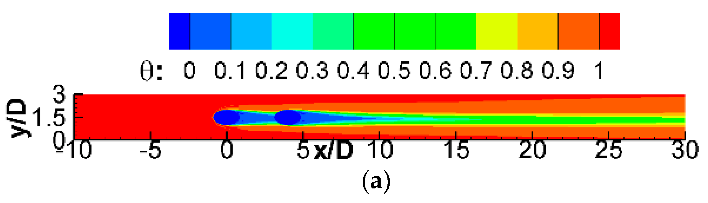
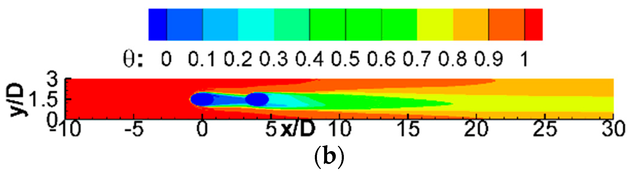
  • The jet orientation of downstream coolant jet has a significant effect on the magnitude of velocity inside the boundary layer. The backward downstream jet could penetrate deep into the hot crossflow and suppress the generation of CVP. Therefore, the hairpin vortices of double rows film cooling with the combination of forward and backward jets are too weak to be identified, which results in the large coverage of coolant-film layer and good improvement of film cooling efficiency of the region behind the downstream film cooling hole;
  • The effect of the blowing ratio of the backward downstream jet onflow structure and heat-transfer features is obvious. There is a pair of anti-CVP generating above the CVP when the blowing ratio of backward downstream jet larger than 0.5. The special vortices could offset the adverse effect of CVP and transport much coolant jet flow to cover the bottom wall. Hence, the large blowing ratio of backward downstream jet would increase the film cooling effectiveness and reduce the SD of the film cooling effectiveness, which is conductive to the improvement of film cooling performance.
The results obtained in current work would help to optimize the film cooling scheme. However, this work only investigates the influence of the backward downstream jet with various blowing ratios on the flow structure and heat-transfer features. Except for the blowing ratio, the inclination angle of the coolant jet is another main affect factor of the film-cooling performance. Therefore, the influence of the backward downstream jet with various inclination angles on the flow structure and heat-transfer features will be the subject of future work. Understanding these important effects by backward downstream jet on film cooling characteristics has an important significance for the study of the mixing mechanism of double rows film cooling with the combination of forward and backward jets.

Author Contributions

Y.S. designed and conducted the numerical analysis. F.C. guided the writing of the manuscript. All the authors discussed the results and commented on the manuscript. All authors have read and agreed to the published version of the manuscript.

Funding

This work was supported by the Research on Smart Operation Control Technologies for Offshore Wind Farms [Grant No. 2019YFE0104800], the Basic Research Program of Jiangsu Province [Grant No. BK20200182], the Natural Science Foundation of Jiangsu Province [Grant No. BK20201161], the Fellowship of China Postdoctoral Science Foundation [Grant No. 2020M671314], the Fundamental Research Funds for the Central Universities of China [Grant No. B210202128], the National Natural Science Foundation of China [Grant No. 51506043] and Open Projects of State Key Laboratory for Strength and Vibration of Mechanical Structures in Xi’an Jiaotong University [Grant No. SV-2020-KF-04].

Conflicts of Interest

The authors declare no conflict of interest.

References

  1. Bogard, D.G.; Thole, K.A. Gas turbine film cooling. J. Propuls. Power 2006, 22, 249–270. [Google Scholar] [CrossRef] [Green Version]
  2. Han, J.C.; Dutta, S.; Ekkad, S.V. Gas Turbine Heat Transfer and Cooling Technology; CRC Press: Boca Raton, FL, USA, 2000. [Google Scholar]
  3. Kamotani, Y.; Greber, I. Experiments on a turbulent jet in a cross flow. AIAA J. 1972, 10, 1425–1429. [Google Scholar] [CrossRef]
  4. Walters, D.K.; Leylek, J.H. A detailed analysis of film-cooling physics: Part I-Streamwise injection with cylindrical holes. J. Turbomach. 2000, 122, 102–112. [Google Scholar] [CrossRef]
  5. McGovern, K.T.; Leylek, J.H. A detailed analysis of film cooling physics: Part II-Compound-angle injection with cylindrical holes. J. Turbomach. 2000, 122, 113–121. [Google Scholar] [CrossRef]
  6. Hyams, D.G.; Leylek, J.H. A detailed analysis of film cooling physics: Part III-Streamwise injection with shaped holes. J. Turbomach. 2000, 122, 122–132. [Google Scholar] [CrossRef]
  7. Brittingham, R.A.; Leylek, J.H. A detailed analysis of film cooling physics: Part IV-Compound-angle injection with shaped holes. J. Turbomach. 2000, 122, 133–145. [Google Scholar] [CrossRef]
  8. Muldoon, F.; Acharya, S. DNS study of pulsed film cooling for enhanced cooling effectiveness. Int. J. Heat Mass Transf. 2009, 52, 3118–3127. [Google Scholar] [CrossRef]
  9. Sultan, Q.; Lalizel, G.; Fenot, M.; Dorignac, E. Influence of coolant jet pulsation on the convective film cooling of an adiabatic wall. J. Heat Transf. 2017, 139, 022201. [Google Scholar] [CrossRef]
  10. Wright, L.M.; McClain, S.T.; Clemenson, M.D. Effect of freestream turbulence intensity on film cooling jet structure and surface effectiveness using PIV and PSP. J. Turbomach. 2011, 133, 041023. [Google Scholar] [CrossRef]
  11. An, B.T.; Liu, J.J.; Zhou, S.J. Effects of mainstream turbulence intensity and coolant-to-mainstream density ratio on film cooling effectiveness of multirow diffusion slot holes. J. Heat Transf. 2019, 141, 122001. [Google Scholar] [CrossRef]
  12. Johnson, B.; Tian, W.; Zhang, K.; Hu, H. An experimental study of density ratio effects on the film cooling injection from discrete holes by using PIV and PSP techniques. Int. J. Heat Mass Transf. 2014, 76, 337–349. [Google Scholar] [CrossRef]
  13. Kelishami, M.K.; Lakzian, E. Optimization of the blowing ratio for film cooling on a flat plate. Int. J. Numer. Methods Heat Fluid Flow 2017, 27, 104–119. [Google Scholar] [CrossRef]
  14. Baek, S.I.; Ryu, J.; Ahn, J. Large eddy simulation of film cooling with forward expansion hole: Comparative study with LES and RANS simulations. Energies 2021, 14, 2063. [Google Scholar] [CrossRef]
  15. Liu, C.L.; Ye, L.; Zhang, F.; Huang, R.; Li, B. Film cooling performance evaluation of the furcate hole with cross-flow coolant injection: A comparative study. Int. J. Heat Mass Transf. 2021, 164, 120457. [Google Scholar] [CrossRef]
  16. Hang, J.; Zhang, J.Z.; Wang, C.H.; Shan, Y. Numerical investigation of single-row double-jet film cooling of a turbine guide vane under high-temperature and high-pressure conditions. Energies 2022, 15, 287. [Google Scholar] [CrossRef]
  17. Zhou, W.; Hu, H. Improvements of film cooling effectiveness by using Barchan dune shaped ramps. Int. J. Heat Mass Transf. 2016, 103, 443–456. [Google Scholar] [CrossRef] [Green Version]
  18. Zhao, M.J.; Bian, Y.F.; Xu, J.J.; Ye, T. Large eddy simulation of film cooling with different upstream obstacles. Int. J. Therm. Sci. 2021, 161, 106722. [Google Scholar] [CrossRef]
  19. Li, X.C. Numerical simulation on fluid flow and heat transfer of film cooling with backward injection. In Volume 5: Fuel Cells, Gas Turbines, Heat Pipes, Jet Impingement, Radiation, Proceedings of the ASME International Heat Transfer Conference-2010, Washington, DC, USA, 8–13 August 2010; American Society of Mechanical Engineers: New York, NY, USA, 2010; pp. 257–265. [Google Scholar]
  20. Park, S.; Jung, E.Y.; Kim, S.H.; Sohn, H.S.; Cho, H.H. Enhancement of film cooling effectiveness using backward injection holes. Int. J. Therm. Sci. 2016, 110, 314–324. [Google Scholar] [CrossRef]
  21. Singh, K.; Premachandran, B.; Ravi, M.R. Experimental and numerical studies on film cooling with reverse/backward coolant injection. Int. J. Therm. Sci. 2017, 111, 390–408. [Google Scholar] [CrossRef]
  22. Zhao, Z.C.; He, L.M.; Dai, S.J.; Shao, S. Computational research on film cooling performance of different shaped holes with backward and forward injection. AIP Adv. 2019, 9, 055009. [Google Scholar] [CrossRef] [Green Version]
  23. Galeazzo, F.C.C.; Donnert, G.; Cardenas, C.; Sedlmaier, J.; Habisreuther, P.; Zarzalis, N.; Beck, C.; Krebs, W. Computational modeling of turbulent mixing in a jet in crossflow. Int. J. Heat Fluid Flow 2013, 41, 55–65. [Google Scholar] [CrossRef]
  24. Duggleby, A.; Camp, J.L.; Laskowski, G. Evaluation of massively-parallel spectral element algorithm for LES of film-cooling. In Proceedings of the ASME Turbo Expo 2013: Turbine Technical Conference and Exposition, San Antonio, TX, USA, 3–7 June 2013; Paper No. GT2013-94281. [Google Scholar]
  25. Chen, S.Y.; Doolen, G.D. Lattice Boltzmann method for fluid flows. Annu. Rev. Fluid Mech. 1998, 30, 329–364. [Google Scholar] [CrossRef] [Green Version]
  26. Chen, Z.; Shu, C.; Tan, D. A simplified thermal lattice Boltzmann method without evolution of distribution functions. Int. J. Heat Mass Transf. 2017, 105, 741–757. [Google Scholar] [CrossRef]
  27. Succi, S. The Lattice Boltzmann Equation: For Fluid Dynamics and Beyond; Oxford University Press: Oxford, UK, 2001. [Google Scholar]
  28. Shangguan, Y.Q.; Wang, X.; Li, Y.M. Investigation on the mixing mechanism of single-jet film cooling with various blowing ratios based on hybrid thermal lattice Boltzmann method. Int. J. Heat Mass Transf. 2016, 97, 880–890. [Google Scholar] [CrossRef]
  29. Shangguan, Y.Q.; Wang, X.; Zhang, H.; Li, Y. Analysis on the mechanism of evolutionary process of counter-rotating vortex pair in film cooling based on hybrid thermal lattice Boltzmann method. Int. Commun. Heat Mass Transf. 2017, 87, 72–83. [Google Scholar] [CrossRef]
  30. Shangguan, Y.Q.; Wang, X.; Zhang, H.; Li, Y. Numerical study on the near-wall characteristics of compound angled film cooling based on hybrid thermal lattice Boltzmann method. Appl. Therm. Eng. 2018, 129, 1670–1681. [Google Scholar]
  31. Hou, S.; Sterling, J.; Chen, S.; Doolen, G.D. A lattice Boltzmann subgrid model for high Reynolds number flows. Fields Instit. Commun. 1994, 6, 151–168. [Google Scholar]
  32. Wang, X.; Shangguan, Y.Q.; Onodera, N.; Kobayashi, H.; Aoki, T. Direct numerical simulation and large eddy simulation on a turbulent wall-bounded flow using lattice Boltzmann method and multiple GPUs. Math. Probl. Eng. 2014, 2014, 742432. [Google Scholar] [CrossRef]
  33. Bardina, J.; Ferziger, J.H.; Rogallo, R.S. Effect of rotation on isotropic turbulence-computation and modelling. J. Fluid Mech. 1985, 154, 321–336. [Google Scholar] [CrossRef]
  34. Schlichting, H.; Gersten, K. Boundary-Layer Theory; Springer: Berlin, Germany, 2000. [Google Scholar]
  35. Chen, A.F.; Li, S.J.; Han, J.C. Film cooling for cylindrical and fan-shaped holes using pressure-sensitive paint measurement technique. J. Thermophys. Heat Transf. 2015, 29, 775–784. [Google Scholar] [CrossRef]
  36. Guo, X.; Schröder, W.; Meinke, M. Large-eddy simulation of film cooling flows with variable density jets. Comput. Fluids 2006, 35, 587–606. [Google Scholar] [CrossRef]
  37. Wang, L.; Li, X.Y.; Ren, J.; Jiang, H. The interaction between upstream and downstream film cooling rows in flow field and heat transfer. Int. J. Therm. Sci. 2020, 149, 106176. [Google Scholar] [CrossRef]
  38. Chen, A.F.; Shiau, C.C.; Han, J.C. Turbine blade platform film cooling with simulated swirl purge flow and slashface leakage conditions. J. Turbomach. 2017, 139, 031012. [Google Scholar] [CrossRef]
  39. Peng, D.; Wang, S.; Liu, Y. Fast PSP measurements of wall-pressure fluctuation in low-speed flows: Improvements using proper orthogonal decomposition. Exp. Fluids 2016, 57, 45. [Google Scholar] [CrossRef]
Figure 1. Flow configuration for double rows film cooling with the combination of forward and backward jets.
Energies 15 04848 g001
Figure 2. D3Q19 discrete velocity model.
Energies 15 04848 g002
Figure 3. Comparison of spanwise-averaged film cooling effectiveness η ¯ between the numerical results and the experimental data.
Energies 15 04848 g003
Figure 4. Comparison of the spanwise-averaged film cooling effectiveness η ¯ of Case 2 for four grid numbers.
Energies 15 04848 g004
Figure 5. Comparison of the x-velocity profiles at (a) x / D = 2.0 and (b) x / D = 2.0 on mid-span plane of Case 1 and Case 2.
Energies 15 04848 g005
Figure 6. Time-averaged x-velocity contour of mid-span plane in (a) Case 1 and (b) Case 2.
Energies 15 04848 g006
Figure 7. Instantaneous coherent structures of (a) Case 1 and (b) Case 2.
Energies 15 04848 g007
Figure 8. Time-averaged non-dimensional temperature on the bottom wall of (a) Case 1 and (b) Case 2.
Energies 15 04848 g008aEnergies 15 04848 g008b
Figure 9. The comparison of the spanwise-averaged film cooling effectiveness η ¯ of Case 1 and Case 2.
Energies 15 04848 g009
Figure 10. Comparison of x-velocity profiles at (a) x / D = 2.0 and (b) x / D = 2.0 on mid-span plane of Case 2–6.
Energies 15 04848 g010
Figure 11. The contours of instantaneous spanwise vorticity ω y on the mid-span plane of double rows film cooling with various backward-downstream-jet blowing ratios of (a) B R = 0.20 , (b) B R = 0.35 , (c) B R = 0.50 , (d) B R = 0.65 , and (e) B R = 0.80 .
Energies 15 04848 g011
Figure 12. The contours of time-averaged streamwise vorticity ω x on the cross sections of (i) x / D = 1.0 , (ii) x / D = 3.0 , and (iii) x / D = 5.0 of double rows film cooling with various backward-downstream-jet blowing ratios of (a) B R = 0.20 , (b) B R = 0.35 , (c) B R = 0.50 , (d) B R = 0.65 , and (e) B R = 0.80 .
Energies 15 04848 g012
Figure 13. The contours of the time-averaged film cooling effectiveness η on the bottom wall of double rows film cooling with various backward-downstream-jet blowing ratios of (a) B R = 0.20 , (b) B R = 0.35 , (c) B R = 0.50 , (d) B R = 0.65 , and (e) B R = 0.80 .
Energies 15 04848 g013
Figure 14. Spanwise-averaged film cooling effectiveness η ¯ of Case 2–6.
Energies 15 04848 g014
Figure 15. Spanwise-averaged standard deviation of the film cooling effectiveness of Case 2–6.
Energies 15 04848 g015
Table 1. Parameters list of simulation cases.
Cases α 1 ( ° ) α 2   ( ° ) B R 1 B R 2
Case 135350.50.5
Case 2351450.50.5
Case 3351450.50.2
Case 4351450.50.35
Case 5351450.50.65
Case 6351450.50.8
Publisher’s Note: MDPI stays neutral with regard to jurisdictional claims in published maps and institutional affiliations.

