Abstract
In the example of the aviation gas turbine engine the problem of monitoring metal wear particles of friction pairs in the oil systems of gas turbine power plants is considered. The solution based on using the multi-channel cluster single-coil eddy current sensor (CSCECS) with sensitive elements in the form of single circuits is proposed. The CSCECS provides the detection of ferromagnetic and non-ferromagnetic particles and their ranking by several size groups. The sensor is invariant to the size (inner diameter) of the monitored oil pipeline and has high throughput and identical sensitivity across all channels. Two variants of the hardware structure of the debris continuous monitoring system (DCMS) prototype implementing the proposed approach are suggested. The first variant is intended for engine bench tests and contains the CSCECS with integrated preamplifiers and forced air cooling of the electronic modules. The second variant of the DCMS prototype involves the use of the uncooled sensors without built-in electronics and it focuses on operation in autonomous mode not only in bench tests but also during the engine normal operation. A brief description of the DCMS operational algorithm is given. The algorithm is the same for both hardware versions but differs at the software implementation level. The correctness of the algorithm for the detection and size identification of the wear metal particles was verified during the laboratory experiments with a total duration of 5 h and 30 min. The DCMS prototype was also examined during the full-scale engine bench tests. The experiments indicated that the number, size, and magnetic properties of the particles detected by DCMS generally corresponded to the number, size, and magnetic properties of the particles fixed by the MetalSCAN oil debris monitoring system which was used for verification of the DCMS functional capability. The results were also confirmed through laboratory analysis of the wipe samples on the debris filters. However, unlike the existing approaches, the design of the CSCECS additionally made it possible to evaluate the oil flow features in the pipeline of the engine lubrication system.
1. Introduction
Gas turbine engines (GTE) for aviation, marine, and terrestrial applications are the typical representatives of the power plants [1]. The use of the engines in critical areas of industry and technology demands their high reliability and service life. It is known that the detection of the wear particles in the engines’ lubrication systems is one of the reliable methods to assess the state of the machines’ moving parts and mechanisms [2,3,4,5,6]. It is obvious that the concentration of wear particles in the oil is insignificant under the normal operating conditions of the power installation, and the particles themselves are of a small size [7]. As soon as the contacting elements are worn out or destroyed the concentration and sizes of the particles are increased like an avalanche. Wang X. et al. [8] with reference to studies in [9,10] indicate that the sizes of wear particles of the considered mechanical systems varied in the range from 1–20 μm in the engine’s regular operation mode to 50–100 μm at the beginning of the destruction process of its moving parts and further to sizes over 200 μm at the end of the product life cycle.
Various methods of on-line debris monitoring in the lubrication systems of power plants are currently known. They are based on optical, capacitive, inductive, ultrasonic, resistive, X-ray, and other principles [7,11,12,13,14,15,16,17,18]. Each of these approaches has its advantages and disadvantages. Nevertheless, the authors of the most up-to-date publications [7,8,17,19,20,21] agree that from a pragmatic standpoint the inductive methods have the best potential for solving the problems of monitoring the state of friction pairs of power plants. The main advantages of the inductive methods are the ability to determine the magnetic properties of the detected metal wear particles (ferromagnetic—Fe and non-ferromagnetic—NFe), which allows us to localize the place of the defect grows, and the insensitivity of the methods to the oil-air medium in the measurement zone. At the same time, the articles indicate the main disadvantage of the inductive methods associated with their low sensitivity to detectable particles (especially to NFe-particles). This situation limits the use of inductive technology in oil pipelines with an internal diameter of more than 20 mm [19,21,22].
Methods for increasing the sensitivity of the inductive debris sensors are well known and widely used. They mainly concern the use of two-dimensional (2D) planar coils or three-dimensional (3D) solenoids, as well as the “concentrators” of the electromagnetic field in the form of ferrite cores or dual excitation sources (synchronous generators with excitation along two axes) [20,23]. However, Wu S. et al. [20] note that such sensors have a small sensing zone and, therefore, a low throughput. «Enlarging the cross-sectional area of the sensor or increasing the flow velocity can improve the throughput…», but «…the sensitivity would be decreased at the same time» [20].
The solutions that provide an acceptable balance between sensors’ sensitivity and throughput are proposed in publications [20,24,25,26]. They are based on the use of multichannel sensors with parallel [25] or sequential [20,24,26] signal processing. However, as it is noted in [20], multichannel sensors with parallel signal processing cannot support the identical sensitivity of the channels to the detected wear particles due to different nominal values of the external capacitances which provide different resonant frequencies. This, together with the high cost and complexity of such systems is a significant limitation of their application. In turn, the sequential channels scanning leads to the loss of information, because it takes some time for the attenuation of the transient process in the elements of the measuring circuit (MC) when switching from channel to channel. The duration of the process is at least 5 μs/channel according to [20].
The article discusses the approach to the development of the continuous monitoring system of wear particles from friction pairs of high-power propulsion systems based on the cluster single-coil eddy current sensor (CSCECS) [1,21,22,27]. CSCECS, in fact, is a multichannel sensor with parallel signal processing. At the same time, the ideas embedded and implemented in the sensor’s design and the device for the conversion of its signals, ensure the high performance of CSCECS, including identical sensitivity across all channels, high throughput, and informativeness of the sensor and the monitoring system in general. All this in combination with the invariance of CSCECS to the size (inner diameter) of the monitored oil pipelines distinguishes it from the sensors considered in [20,24,25,26]. The description of the hardware structure and operational algorithm of the debris continuous monitoring system (DCMS) prototype and the results of its laboratory and bench tests are also presented.
2. The Proposed Approach
The main features of the proposed approach to detecting metal wear particles in the engines’ lubrication systems by applying the CSCECS are reflected with different degrees of detail in publications [1,21,22,27,28,29,30,31]. However, the understanding of the DCMS functioning, as well as the analysis of the test results is impossible without an explanation of the principles implemented in the system of the conversion of the CSCECS parameters. Therefore, the article will not be complete without a brief description of the methods which are used for obtaining information about the wear particles of the bearing assemblies in the lubrication systems of high-powered propulsion installations.
As already noted, the main idea of the proposed solution is the separation of the general oil stream on the input of the sensor into N independent streams with a smaller cross-section area (Figure 1) [28]. The cross-section area of each of the N streams is selected so that the wear particles will not be blocked in the stream (the sensor should not work as a debris filter), and the acceptable sensitivity of the sensor to the smallest of the detectable metal particles will be ensured. Concurrently, the overall cross-sectional area of all N streams should be roughly equal to the total oil flow area on the sensor’s input.
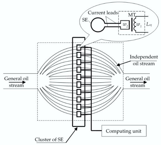
Figure 1.
Splitting of the general oil stream into N independent streams and placing the single-coil sensing elements in them [21].
The sensing elements (SE) are installed in each independent stream and form a cluster of SE. Every SE is connected to the individual MC using current leads and the matching transformer (MT). The changes of the MT’s equivalent inductance (Leq) are converted into electric signals in differential MC based on the Blumlein transformer measuring bridge. One leg of the bridge includes the working SE (SE1) and the other contains the similar compensation SE (SE2) which is installed in the same sensor’s oil channel with an axial shift by a specified distance h (Figure 2). When a channel is free of metal particles the MC is balanced and its output signal is about zero level. It should be noted that SE1 and SE2 are in the same temperature conditions and therefore the differential MC also allows to compensate for the temperature effect on the sensor [32].
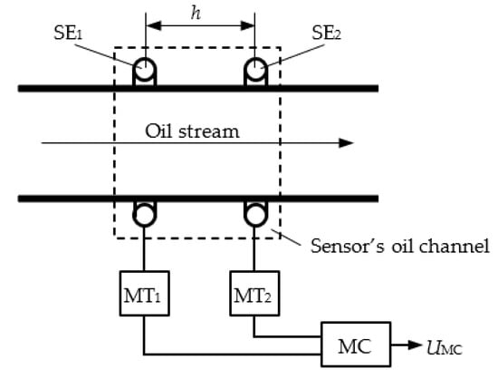
Figure 2.
SE1 and SE2 location in CSCECS oil channel.
Two consecutive voltage pulses of the opposite polarity are formed at the MC output when the metal particle moves sequentially through SE1 and SE2 contours (Figure 3). The amplitude of the pulses is determined by the chip’s size and its location in the plane of the contour—the larger the particle and the closer it is to the edge of the contour, the greater the signal amplitude. The polarity of the pulses reflects the chip’s magnetic property. As shown in Figure 3a the pulse at the MC output changes from positive to negative when a non-ferromagnetic particle passes through the SE1 and SE2 contours (Figure 3a). On the contrary, the pulse polarity changes from negative to positive when a ferromagnetic particle passes through the same SE1 and SE2 contours (Figure 3b).
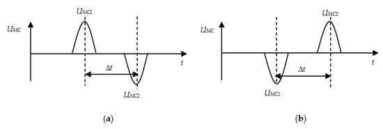
Figure 3.
Signals at the output of the differential MC when a non-magnetic (a) and magnetic (b) metal particles pass through SE1 and SE2 contours [21].
The existence of two consecutive pulses of the opposite polarity on the fixed distance when the particles pass through the oil channel of the sensor is also a good diagnostic property that makes it possible to uniquely identify a signal at the CSCECS output as a signal from a metal particle and to reduce the number of false alarms (type I errors).
Two SE installed in the same sensor’s oil channel at a fixed distance from each other also provide an assessment of the oil stream rate in the lubrication system of a power plant. The weight of the particles is assumed to be small, and it is accepted that they move at a stream rate. In this case, the oil stream rate is determined by calculating the time interval (Δt) between the amplitude values of the signal at the MC output (they correspond to the moments of the chip’s passage through the SE1 and SE2 contours) and the distance h between two SEs [29].
The size of the wear particle is defined by the amplitude value of the MC output signal (UMC1, UMC2, Figure 3). At the same time, the magnitude of the signal amplitude depends not only on the size of the detectable particle but also on its position (r) in the SE contour, and the dependence UMC(r) is purely nonlinear. It should be noted that in practice the determination of the exact size of the wear particles is often useless. To determine the defect nature in the bearing it is sufficient to assign a particle to a given size group. One of such methods is suggested in [30]. Its implementation requires the preliminary obtaining of the families of calibration characteristics of the DCMS measuring channels in the form of approximated dependences of voltages (more often digital codes) at the MC outputs on the position of the particle with given magnetic properties and size in the SE contour. For this purpose, a specialized graduation stand with a three-axial movement device is used. The casing funnel is removed from the sensor to provide the access to the SE. The probe with a calibrated particle of the specified size and magnetic property is fixed in the device and the dependences of the MC output voltages (digital codes) on the chip’s position in SE contour are taken. The movement of the probe in the SE contour is controlled by dial indicators with a resolution of 0.01 mm. The calibration experiment is repeated for a given number of particles with specified dimensions and magnetic properties. Each calibration characteristic is approximated by the polynomial function.
In DCMS operating mode, the magnitude of the measured voltage (the extreme of digital code) at the MC output is fixed when the metal particle passes through the SE contour. The assignment of the detected particle to a specified group is carried out on the basis of calibration characteristics under the assumption that the particle’s position in the SE contour is random and equally possible [30]. If the oil flow in the CSCECS channel can be considered as laminar and the oil stream velocity through the sensor is known (or can be measured), then the equivalent size of the metal particle can be determined with more accuracy [31]. However, it should be noted that such conditions are sooner an exception than a rule in the real operation of propulsion systems.
3. DCMS Prototype: Structure and Operational Algorithm
Figure 4 presents two variants of the hardware structure of the DCMS prototype implementing the discussed approach. The variants differ from each other in the sensors used and the tools of secondary information processing.
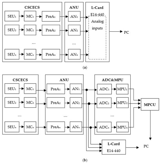
Figure 4.
Variants of the DCMS hardware structure with cooled (a) and uncooled (b) CSCECS.
Both variants of the DCMS prototype contain CSCECS with n identical oil channels. The total cross-sectional area of the channels is equal to the cross-sectional area of the oil stream at the sensor’s inlet. Each oil channel is covered by two SE (in Figure 4 they are defined as SE Units—SEU1 … SEUn), which are connected to the individual MC based on a differential circuit with the Blumlein transformer measuring bridge [32]. The MC’s output voltage is amplified (pre-amplification units PreA1 ... PreAn) and normalized to the level corresponding to the required input signal level of the selected ADC (amplification and normalization units AN1 ... ANn). At the same time, the pre-amplification electronic units (PreA1 ... PreAn) in the variant in Figure 4a are placed directly in the CSCECS body, and in the variant in Figure 4b they are removed from the sensor and placed in the amplification and normalization unit (ANU).
Each of the presented variants has its obvious advantages and disadvantages. In particular, the effect of the influence of parasitic parameters of the communication line between CSCECS and ANU on the conversion result is excluded in the case when the electronic pre-amplification units are embedded in the sensor (Figure 4a). However, this type of sensor’s design requires the forced air cooling of the electronic modules. It is possible in bench conditions but is unacceptable during DCMS operation on the engine. In turn, the removing of the electronic parts outside the CSCECS body (Figure 4b) degrades the characteristics of the measuring channels of the system and reduces, among other things, the signal-to-noise ratio. However, it allows for the uncooled design of CSCECS which is preferable from a practical point of view.
The hardware structures in Figure 4a,b also differ by means of analog-to-digital conversion and secondary processing of SCECS signals. The first variant of the DCMS prototype (Figure 4a) is applicable only in bench tests of power plants. Therefore, emphasis was placed here on the use of standard means of analog-to-digital conversion and signal processing under the control of a personal computer (PC). In particular, the external ADC module E14-440 of the L-Card company (Russia) was selected [33]. The module contains a 14-bit/400 kHz ADC for connecting up to 16 differential channels and has a software-controlled configuration of data acquisition parameters. In addition, the module has its own digital signal processor (DSP) ADSP-2185M [34], which makes it possible to implement specialized algorithms for real-time signal processing at the DSP programming level. The module is connected to other devices via the standard USB 2.0 and this ensures the module’s easy integration with the PC used to control the acquisition, processing, and visualization of the information about the wear particles in the engine’s lubrication system.
The second variant of the DCMS prototype (Figure 4b) is focused on operation in an autonomous mode without external control from a PC. At the same time, its possibilities are not limited to bench tests of propulsion systems only and they can also be extended to the normal operating conditions of the power plants. The “digital” part of this DCMS variant is based on the ADC and MPU units with individual analog-to-digital converters (ADC) and microprocessors (MPU) that provide the independent asynchronous acquisition and processing of the information from the measuring channels of the prototype. The separate microprocessor control unit (MPCU) is used to interact with external devices. MPCU provides firmware loading and configuring as well as the transmission of the recorded information about the detected wear particles to the engine’s health monitoring unit or (and) PC. Communication with external devices is carried out via ARINC 429 and RS-485 protocols, respectively. The standard means of data acquisition and data processing are also included in the structure presented in Figure 4b (ADC module E14-440). It allows us to use the previously developed software without additional customization and simplifies the debugging of the microprocessor part of the system.
As for the operational algorithms of the DCMS prototypes, they are conceptually identical for both variants of the hardware presented in Figure 4a,b. The difference appears only at the software implementation level where the hardware features should be considered. In general, the sequence of operations related to the acquisition and processing of the measuring information about wear particles in the power plant’s lubrication system can be represented by the following verbal algorithm:
- Memory areas in the form of a ring buffer are allocated in the RAM to accumulate the results of each CSCECS channel’s scanning.
- Continuous data input from the ADC (individual or E14-440 L-Card module) into the system RAM is carried out. When a part (usually a half) of the selected area is filled, an interrupt is generated, and a data fragment (“frame”) is transmitted for further processing. Data input from the ADC is carried out into the remaining memory area, ensuring the formation of the subsequent “frame”, etc. The pointer is set to its beginning when the end of the memory buffer is reached. The data acquisition process is repeated cyclically until the command “stop” is received or the system is turned off.
- Code arrays formed in the RAM are read within one “frame” on interruption from the CSCECS channel scanning subroutine. The informative component of the signal in each sensor channel is extracted. If the signal corresponding to a metal particle is detected, then data are processed to define the magnetic properties of the chip and to assign it to a specific dimension group. Data processing is performed sequentially in several stages:
- Filtration. The simple moving average (SMA) filter or band-stop filter (BSF) is used.
- Algorithmic correction of the temperature effect in the measuring area. It completes the hardware methods of automatic stabilizing of a signal’s constant component on the output of the measuring circuit. In accordance with the algorithm, the averaged code in the absence of the metal particles in the SE’s sensitivity zone is determined at each data processing cycle and then the digital codes in the array with scanning results are corrected by that amount. Two algorithms of calculation of the averaged code are provided. The first one is based on the construction of the codes distribution and selection of the most common code (histogram) and the second requires averaging a sample of codes of a given size with sliding boundaries.
- Signals’ amplitude detection. It allows to identify the informative signal against the background noise component and to determine its amplitude value. The procedure starts when a new code sample exceeds the “discrimination” zone defined by the maximum possible amplitude of the “noise” in the CSCECS measuring channels. The digital code corresponding to the amplitude value of the informative signal is determined using an “adaptive threshold algorithm” [35], which is more resistant to the extrema dispersion than the traditional approaches. The additional analysis of the system’s spurious alarms is carried out at the same stage. It is based on the diagnostic property of the existence of two identical in amplitude, but opposite in phase signals after the time corresponding to the passage of a metal particle of the distance between the working and the compensation SE. If the opposite signal has been detected, the previously determined value of the digital code is fixed in the system memory together with the time stamp of its appearance. Otherwise, the detection result is discarded as false.
- Determining the magnetic properties of the particle and its assignment to a dimension group. If the positive result of the informative signal’s detecting is obtained at the previous stage, then the procedure for determining the magnetic properties and assigning the particle to the specific dimension group is started. A particle is recognized as non-magnetic (NFe-particle) if the value of the digital code fixed in the system memory is greater than the zero level and magnetic (Fe-particle) if it is below it. Assignment of a particle to one or another dimension group is realized on the basis of preliminarily obtained families of calibration characteristics of the CSCECS using a probabilistic algorithm as it was described in Section 2 and in [30].
- The counters of detected wear particles are updated. The information is passed to the user or to the engine’s health monitoring unit for decision-making.
4. Experimental Testing of the DCMS Prototype
The functionality of the DCMS prototype was tested in laboratory conditions and on the JSC “UEC-Aviadvigatel” test bench with a connection to the GTE lubrication system. The variant of the DCMS prototype presented in Figure 4a with cooled CSCECS was used in both tests. CSCECS contained 6 oil channels with the inner diameter of each channel equal to 8 mm. The sensor’s dimensions were 210 mm × 76 mm × 92 mm (length × width × height) and its weight was 1.9 kg.
The goal of the laboratory experiments was to verify the correctness of the algorithms for the detection and size identification of the metal particles. For this purpose, a specialized installation was developed. It contained an adjustable DC source, a miniature DC motor, a system of guide rollers, a frame, and a set of non-conductive filaments (lines) with calibrated metal particles of specified sizes (0.3; 0. 5; 0.8 mm) and magnetic properties (Cu, Fe). CSCECS was installed on the frame and through one of its available oil channels, the filaments with particles were pulled. Power supply of a miniature DC motor set the filaments system in cyclic motion, which simulated the passage of the particles through the sensor channel. Regulation of the supply voltage made it possible to change the velocity of the filaments’ movement through the sensor’s channel, thereby simulating the different engine’s operation modes and the oil pumping volumes through the sensor associated with them.
The families of calibration characteristics of the CSCECS channels used in the experiments in the form of approximated dependences of the digital code (C) at the output of the 14-bit ADC L-Card E14-440 on the radial position (r) of magnetic and non-magnetic particles with the equivalent sizes of 0.3; 0.5; 0.8 mm in the plane of the SE contour are presented in Table 1.

Table 1.
Approximated families of calibration characteristics of the CSCECS channels.
The experiment consisted of 3 series with a total duration of 5 h and 30 min. In the first experiment (Test 1), the filaments with two metal particles, magnetic (Fe) and non-magnetic (Cu), 0.5 mm in size, glued into them were used. In the second experiment (Test 2), the filaments with magnetic and non-magnetic particles of 0.8 mm were used. Additionally, finally, in the third experiment (Test 3), the filaments with 4 particles—two magnetic and non-magnetic of 0.5 and 0.8 mm, were used. The speed of particle movement through the sensor was set to 1.0 m/s in the experiments. The maximum possible amplitude of the “noise” signal in the CSCECS measuring channels, which defines the “discrimination” zone in signals’ amplitude detection procedure and in fact is the sensitivity threshold used to determine the presence or absence of the informational signal at the MC output, was about 30 digital code units. Laboratory-determined SNR for the informational signal from the NFe(Cu)-particle with the equivalent diameter of 0.3 mm was 9.5 dB.
Summarized results of the experiments are given in Table 2. It contains the total number of the detected particles and the results of their ranking by dimension groups according to the algorithms implemented in the DCMS prototype.
Table 2.
Results of the DCMS laboratory experiments.
As can be seen from the presented data, the number of the detected magnetic and non-magnetic particles in each test is almost the same. Insignificant downward differences in the number of the detected non-magnetic particles are primarily due to the lower sensitivity of the CSCECS to them. For the first and second experiments (Test 1 and Test 2), the correctness of the algorithm of particles ranking into specified dimension groups was also evaluated. It was identified that for magnetic particles with an equivalent size of 0.5 mm the maximum error in referring to the incorrect dimension group was 3.14% and for magnetic particles with an equivalent size of 0.8 mm the same error reached 0.33%. In turn, all detected non-magnetic particles with an equivalent size of 0.5 mm were correctly assigned to their dimension group, and the percentage of incorrectly detected non-magnetic particles with an equivalent size of 0.8 mm did not exceed 0.4%.
During the full-scale tests of the DCMS prototype under the operating conditions the CSCECS was built into the regular oil line of GTE installed on the test bench of JSC “UEC-Aviadvigatel”. The inner diameter of the pipeline was 20 mm. The working medium in the engine’s lubrication system was the type II synthetic aviation oil with a viscosity of 5 mm2/s (cSt) according to the MIL-PRF-23699 and SAE AS 5780 specifications. DCMS readings were verified by the MetalSCAN oil debris monitoring system (GasTops, Canada) [12], whose sensor was installed in the same oil line just before CSCECS (Figure 5a). The rest of the DCMS equipment, including the amplification and normalization unit (AUN), power supply unit (PSU), L-Card ADC module, etc. (Figure 5b) was located on an individual rack at 8 m from SCECS. The operation of the system was controlled, and the readings were monitored using an additional remote workstation located in the operator’s cabin of the bench at a distance of 40 m.
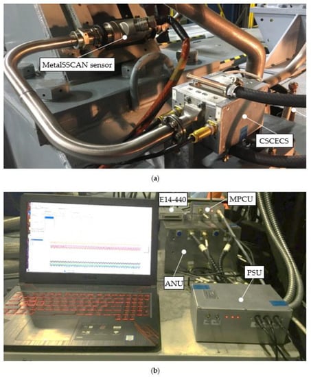
Figure 5.
Installation of the DCMS equipment on the test bench of JSC “UEC-Aviadvigatel”: CSCECS and MetalSCAN sensor (a), DCMS units (b).
By analogy with laboratory experiments, the maximum possible amplitude of the “noise” signal in the CSCECS measuring channels was defined under bench conditions before DCMS tests. The determined SNR for the informational signal from the same NFe(Cu)-particle with the equivalent diameter of 0.3 mm deteriorated to 5.1 dB but it was still sufficient to detect the informational signal. The “discrimination” zone (sensitivity threshold) in the signals’ amplitude detection procedure was changed to 50 digital code units for bench tests.
DCMS was tested in all GTE operating modes—from idle to take-off. In a number of the experiments, the laboratory analysis of the oil filters for the chips’ presence was carried out in addition to comparing the results of metal particles detection by DCMS and MetalSCAN.
The bench tests indicated that the number, size, and magnetic properties of the particles detected by DCMS generally corresponded to the number, size, and magnetic properties of the particles fixed by MetalSCAN oil debris monitoring system. This was also confirmed by laboratory analysis of the wipe samples on the debris filters. At the same time, the cluster design of the CSCECS additionally made it possible to evaluate the oil flow features in the pipeline of the GTE lubrication system.
Figure 6 demonstrates the distribution of the metal particles fixed by the DCMS over the oil channels of the CSCECS during the test period. The absolute number of the detected particles in each specific channel of the CSCECS is marked by numerals, and the filling indicates a relative frequency of their appearance in the channel (the darker tone corresponds to more often detection of the particles in the sensor’s channel). As shown in Figure 6, the great bulk of the particles passes through the oil channels number 1, 4, and 5. Assuming that the mass of each particle was small and the velocity of its movement along the oil channel can be taken equal to the velocity of the oil flow in the pipeline, such distribution of the particles over the CSCECS channels indicates that the oil stream was twisted and pressed against the lower left wall of the oil pipeline.
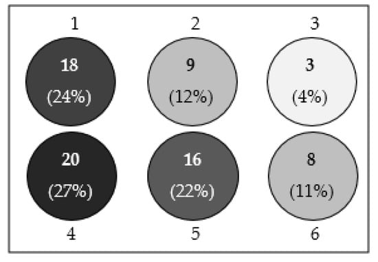
Figure 6.
Distribution of the metal particles over the oil channels of the CSCECS.
In turn, the analysis of signal amplitudes corresponding to the movement of a single particle sequentially through SE1 and SE2, located in the same oil channel of the CSCECS (see Figure 2), allows us to conclude that the oil flow in the channel is uneven. The oscillogram in Figure 7a demonstrates that the amplitude of the pulse corresponding to the movement of the metal particle through SE1 is greater than the amplitude of the pulse corresponding to the movement of the same particle through SE2. This indicates that the monitored particle moved from the wall of the oil channel to its center during the passage of the distance between the SEs.
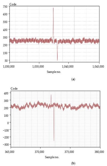
Figure 7.
Displacement of a metal particle inside CSCECS oil channel: from the wall to the center of the channel (a) and from the center of the channel to its wall (b).
In addition, conversely, Figure 7b shows the oscillogram of the MC output signal where the amplitude of the pulse corresponding to the movement of the metal particle through SE1 is lower than the amplitude of the pulse corresponding to the passage of the same particle through SE2. This means that the particle shifted from the middle of the oil channel to its wall while passing from one SE to another.
5. Conclusions
The prototype of the system for continuous monitoring of the wear particles of friction pairs in the oil systems of gas turbine power plants proposed in the article has been experimentally tested in laboratory and bench conditions. The goal of the laboratory experiments was to verify the correctness of the algorithms for the detection and size identification of the metal particles. During the tests, it was identified that for magnetic particles with an equivalent size of 0.5 mm the maximum error in referring to the incorrect dimension group was 3.14%, and for magnetic particles with an equivalent size of 0.8 mm the same error reached 0.33%. In turn, all detected non-magnetic particles with an equivalent size of 0.5 mm were correctly assigned to their dimension group, and the percentage of incorrectly detected non-magnetic particles with an equivalent size of 0.8 mm did not exceed 0.4%.
The full-scale tests of the DCMS prototype under the operation conditions on the JSC “UEC-Aviadvigatel” bench have confirmed the feasibility of the adopted approach and the main technical characteristics of the system prototype. The experiments indicated, among others, that the number, size, and magnetic properties of the particles detected by DCMS generally corresponded to the number, size, and magnetic properties of the particles fixed by the MetalSCAN oil debris monitoring system which was used for verification of the DCMS functional capability. The results were also confirmed through laboratory analysis of the wipe samples on the debris filters. However, the multichannel design of CSCECS makes it possible not only to detect the metal particles in the engine lubrication system, but also, under certain assumptions, to evaluate the features of the oil flow in the pipelines, which increases the information content of the monitoring process.
At the same time, it was established during the bench tests that the signals’ amplitude detection algorithm is sensitive to constant interference or to a group of contiguous interferences which leads to false chips registration. So, the direction of further research is to increase the noise protection of the system and its individual components and to improve the algorithms of signal detection and particle recognition.
6. Patents
Patent RF, no. 2646520, 2018: Method for detecting metal wear particles in the oil stream of a running gas turbine engine.
Patent RF, no. 2668513, 2018: Method for detecting metal particles in the oil of the friction unit lubrication system and determining the oil flow.
Patent RF, no. 2674577, 2018: Method for detecting metal particles in the lubrication system of friction units of power plants with the grouping of the particles by size.
Patent RF, no. 2724309, 2020 Method for detecting and evaluating the size of single metal particles in the system for lubricating friction pairs in power plants.
Author Contributions
Conceptualization, S.B., A.S. and Y.S.; methodology, S.B. and Y.S.; data curation, S.B. and Y.S.; investigation, A.B., S.B., F.M., M.L. and P.P.; resources, A.B., M.L. and F.M.; software, V.B. and P.P.; validation, A.B., S.B., A.S. and Y.S., writing—original draft preparation, S.B.; writing—review and editing, S.B., A.S. and Y.S. All authors have read and agreed to the published version of the manuscript.
Funding
The research was funded by the Ministry of Science and Higher Education of the Russian Federation, R&D registration number 122032400128-7 and JSC «UEC-Aviadvigatel», contract number №00000000020956181023/6.
Institutional Review Board Statement
Not applicable.
Informed Consent Statement
Not applicable.
Data Availability Statement
Not applicable.
Conflicts of Interest
The authors declare no conflict of interest.
Abbreviations
| ADC | analog-to-digital converter |
| AN | amplifier-normalizer |
| ANU | amplification and normalization unit |
| BSF | band-stop filter |
| CSCECS | cluster single-coil eddy current sensor |
| DC | direct current |
| DCMS | debris continuous monitoring system |
| DSP | digital signal processor |
| GTE | gas turbine engine |
| MC | measuring circuit |
| MPCU | microprocessor control unit |
| MPU | microprocessor unit |
| MT | matching transformer |
| PC | personal computer |
| PreA | preamplifier |
| PSU | power supply unit |
| RAM | random-access memory |
| SE | sensing element |
| SEU | sensing elements unit |
| SMA | simple moving average |
| SNR | signal-to-noise ratio |
References
- Blinov, A.; Borovik, S.; Luchsheva, M.; Muhutdinov, F.; Sekisov, Y. Monitoring the state of power plants’ friction pairs on the basis of single-coil eddy-current sensors. J. Phys. Conf. Ser. 2021, 1891, 012053. [Google Scholar] [CrossRef]
- Miller, J.; Kitaljevich, D. In-line oil debris monitor for aircraft engine condition assessment. IEEE Aerosp. Conf. Proc. 2009, 6, 49–56. [Google Scholar]
- Inozemtsev, A.A.; Nihamkin, M.A.; Sandratskiy, V.L. Fundamentals of the Design of Aircraft Engines and Power Plants. Vol. 5: Automation and Control of Aircraft Engines and Power Plants; Mashinostroeniye: Moscow, Russia, 2008; p. 185. [Google Scholar]
- López de Calle, K.; Ferreiro, S.; Roldán-Paraponiaris, C.; Ulazia, A. A context-aware oil debris-based health indicator for wind turbine gearbox condition monitoring. Energies 2019, 12, 3373. [Google Scholar] [CrossRef] [Green Version]
- Gryadunov, K.I.; Kozlov, A.N.; Nemchikov, M.L.; Melnikova, I.S. Diagnostics of aircraft engines by the content of metals in oil. Civ. Aviat. High Technol. 2019, 22, 35–44. [Google Scholar] [CrossRef]
- Shaporova, E.A.; Stoyko, S.O. Technical diagnostics of aircraft engines. In Proceedings of the V International Scientific and Practical Conference «Aviation: History, Modernity, Development Prospects», Minsk, Belarus, 22 October 2020. [Google Scholar]
- Wu, X.; Zhang, Y.; Li, N.; Qian, Z.; Liu, D.; Qian, Z.; Zhang, C. A New inductive debris sensor based on dual-excitation coils and dual-sensing coils for online debris monitoring. Sensors 2021, 21, 7556. [Google Scholar] [CrossRef] [PubMed]
- Wang, X.; Sun, H.; Wang, S.; Huang, W. Cross-correlation algorithm-based optimization of aliasing signals for inductive debris sensors. Sensors 2020, 20, 5949. [Google Scholar] [CrossRef] [PubMed]
- Edmonds, J.; Resner, M.S.; Shkarlet, K. Detection of precursor wear debris in lubrication systems. In Proceedings of the 2000 IEEE Aerospace Proceedings, Big Sky, MT, USA, 25–25 March 2000. [Google Scholar]
- Tucker, J.E.; Reintjes, J.; Galie, T.R.; Schultz, A.; Lu, C.; Tankersley, L.L.; Sebok, T.; Holloway, C.; Howard, P.L. Lasernet fines optical wear debris monitor: A Navy shipboard evaluation of CBM enabling technology. In Proceedings of the 54th Meeting of the Society for Machinery Failure Prevention Technology, Virginia Beach, VA, USA, 1–4 May 2000. [Google Scholar]
- Myshkin, N.K.; Markova, L.V. Methods and Instruments for Condition Monitoring of Lubricants. In On-line Condition Monitoring in Industrial Lubrication and Tribology. Applied Condition Monitoring; Haddar, M., Bartelmus, V., Chaari, F., Zimroz, R., Eds.; Springer: Cham, Switzerland, 2018; Volume 8, p. 241. [Google Scholar]
- Haliullin, V. Oil system is under continuous monitoring. Inf. Tech. Bull. Perm Gas Turbines 2012, 22, 46–48. [Google Scholar]
- Bogue, R. Sensors for condition monitoring: A review of technologies and applications. Sens. Rev. 2013, 33, 295–299. [Google Scholar] [CrossRef]
- Wu, T.; Wu, H.; Du, Y.; Peng, Z. Progress and trend of sensor technology for on-line oil monitoring. Sci. China Technol. Sci. 2013, 56, 2914–2926. [Google Scholar] [CrossRef]
- Hamilton, A.; Cleary, A.; Quail, F. Development of a novel wear detection system for wind turbine gearboxes. IEEE Sens. J. 2014, 14, 465–473. [Google Scholar] [CrossRef]
- Gebarin, S. On-line and In-line Wear Debris Detectors: What’s Out There? Available online: http://www.machinerylubrication.com/Read/521/in-line-wear-debris-detectors (accessed on 30 May 2022).
- Cassidy, K. Qualification of an On-Line Bearing and Gear Health Monitoring Technique for In-Service Monitoring of Aircraft Engines and Helicopter Transmissions. Available online: http://www.gastopsusa.com/knowledge_center_documents/1/MetalSCAN_ISHM07.pdf (accessed on 30 May 2022).
- Harkemanne, E.; Berten, O.; Hendrick, P. Analysis and testing of debris monitoring sensors for aircraft lubrication systems. Proceedings 2018, 2, 461. [Google Scholar]
- Xiao, H.; Wang, X.; Li, H.; Luo, J.; Feng, S. An inductive debris sensor for a large-diameter lubricating oil circuit based on a high-gradient magnetic field. Appl. Sci. 2019, 9, 1546. [Google Scholar] [CrossRef] [Green Version]
- Wu, S.; Liu, Z.; Yuan, H.; Yu, K.; Gao, Y.; Liu, L.; Pan, X. Multichannel inductive sensor based on phase division multiplexing for wear debris detection. Micromachines 2019, 10, 246. [Google Scholar] [CrossRef] [PubMed] [Green Version]
- Borovik, S.; Sekisov, Y. Single-coil eddy current sensors and their application for monitoring the dangerous states of gas-turbine engines. Sensors 2020, 20, 2107. [Google Scholar] [CrossRef] [PubMed] [Green Version]
- Borovik, S.Y.; Sekisov, Y.N.; Blinov, A.V.; Muhutdiniv, F.I. Transformation of the information in the monitoring system of wear-and-tear particles of friction pairs on the basis of the group of single-coil eddy-current sensitive elements. Turbiny Dieseli 2017, 73, 10–17. [Google Scholar]
- Zeng, L.; Yu, Z.; Zhang, H.; Zhang, X.; Chen, H. A high sensitive multi-parameter micro sensor for the detection of multi-contamination in hydraulic oil. Sens. Actuators A Phys. 2018, 282, 197–205. [Google Scholar] [CrossRef]
- Du, L.; Zhe, J. A high throughput inductive pulse sensor for online oil debris monitoring. Tribol. Int. 2011, 44, 175–179. [Google Scholar] [CrossRef]
- Du, L.; Zhe, J. Parallel sensing of metallic wear debris in lubricants using undersampling data processing. Tribol. Int. 2012, 53, 28–34. [Google Scholar] [CrossRef]
- Zhu, X.; Du, L.; Zhe, J. A 3x3 wear debris sensor array for real time lubricant oil conditioning monitoring using synchronized sampling. Mech. Syst. Signal Process. 2017, 83, 296–304. [Google Scholar] [CrossRef] [Green Version]
- Borovik, S.Y.; Sekisov, Y.N.; Blinov, A.V.; Luchsheva, M.V.; Mukhutdinov, F.I. Tools for diagnostics and assessment of remaining lifetime of friction units at operation of gas turbine engines. Optoelectron. Instrument. Proc. 2021, 57, 675–682. [Google Scholar] [CrossRef]
- Borovik, S.Y.; Korshykov, I.G.; Sekisov, Y.N.; Belosludtsev, V.A. Method for Detecting Metal Wear Particles in the Oil Stream of a Running Gas Turbine Engine. Patent RF 2646520, 5 March 2018. [Google Scholar]
- Borovik, S.Y.; Korshykov, I.G.; Sekisov, Y.N.; Belosludtsev, V.A. Method for Detecting Metal Particles in the Oil of the Friction Unit Lubrication System and Determining the Oil Flow. Patent RF 2668513, 1 October 2018. [Google Scholar]
- Borovik, S.Y.; Korshykov, I.G.; Belosludtsev, V.A.; Sekisov, Y.N. Method for Detecting Metal Particles in the Lubrication System of Friction Units of Power Plants with Grouping of the Particles by Size. Patent RF 2674577, 11 December 2018. [Google Scholar]
- Belopukhov, V.N.; Borovik, S.Y.; Korshykov, I.G.; Sekisov, Y.N. Method for Detecting and Evaluating the Size of Single Metal Particles in the System for Lubricating Friction Pairs in Power Plants. Patent RF 2724309, 22 June 2020. [Google Scholar]
- Sekisov, Y.N.; Skobelev, O.P.; Belenki, L.B.; Borovik, S.Y.; Raykov, B.K.; Slepnev, A.V.; Tulupova, V.V. Methods and Tools for Measuring Multidimensional Displacements of Structural Components of Power Plants; Sekisov, Y.N., Skobelev, O.P., Eds.; Izd. SamNTs RAN: Samara, Russia, 2001; p. 188. [Google Scholar]
- Module E-440. Technical Description and Operating Instructions; CJSC «L-Card»: Moscow, Russia, 2003; p. 91.
- DSP Microcomputer ADSP-2185M. Available online: https://www.analog.com/media/en/technical-documentation/data-sheets/ADSP-2185M.pdf (accessed on 30 May 2022).
- Belpukhov, V.N.; Malov, A.N.; Podvigin, V.N. Device for Fixing the Moment When the Back Edge of the Pulse Passes a Given Level. Author’s certificates of the USSR. no. 4332427/24-21. 1990. Available online: https://patentdb.ru/patent/1550608 (accessed on 30 May 2022).
Publisher’s Note: MDPI stays neutral with regard to jurisdictional claims in published maps and institutional affiliations. |
© 2022 by the authors. Licensee MDPI, Basel, Switzerland. This article is an open access article distributed under the terms and conditions of the Creative Commons Attribution (CC BY) license (https://creativecommons.org/licenses/by/4.0/).