1. Introduction
Keeping the wind energy conversion systems (WECS) connected to the grid during short-term faults has been a major requirement from the grid operators, especially in the wake of higher penetration of wind into the grid. The WECS are now expected to behave as an equal partner to conventional power generating plants and provide the enhanced control of wind turbines (WT) that keeps the grid afloat even during disturbances. Fault ride-through (FRT) has now become an important requirement for the power providers to manage diverse grid conditions, which may include a terminal voltage limit and active/reactive power recovery. The requirements listed under wind farm transmission grid codes for different countries have been described in [
1]. These grid codes include the importance of fault ride-through during severe grid faults.
Among the variable and fixed speed WECS, variable speed WECS are preferred, because of their various advantages, viz., efficient operation at various wind speeds, decreased mechanical stress, and the possibility of being used as direct (gearless) drive systems [
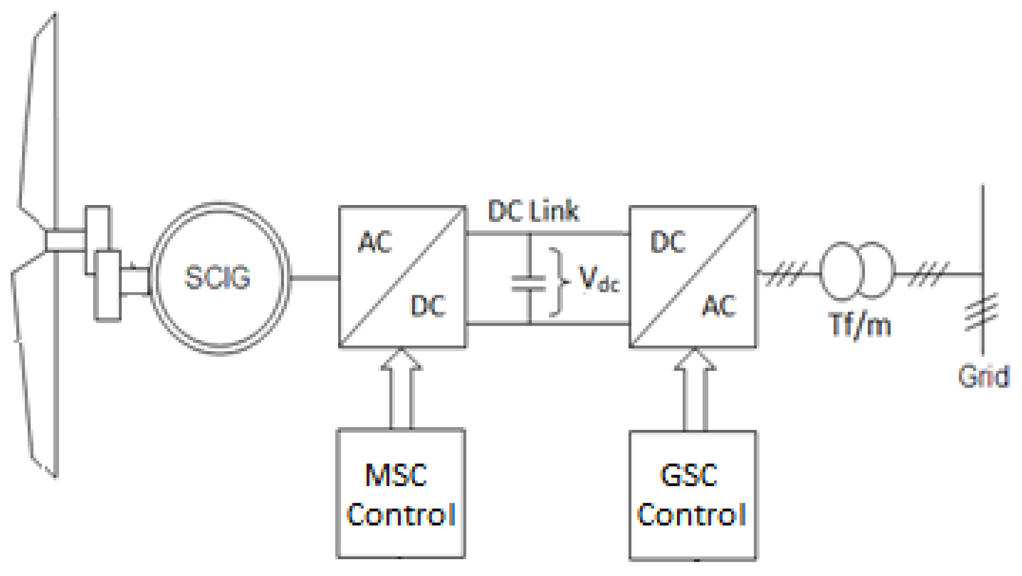
2]. In variable speed, the WECS configured with a squirrel cage induction generator (SCIG) uses a set of two full-rated converters (FRC) that provide the interface between generator and grid. SCIG’s ease of availability at low cost, ability to operate in harsh environments, and decreasing cost of power electronics make it a lucrative option to be used for WECS [
3]. In [
4,
5], it is established that STATCOM, dynamic voltage restorers (DVRs), and the static VAR compensators are capable of improving the FRT potential of WECS. In [
6], a non-linear controller is incorporated with the grid side converter (GSC) controller that limits the current rise within the safe value and also the power transfer to the grid. In [
7], the use of a controlled, but static, braking resistor is presented. The braking resistor is placed in the dc-link, which dissipates the extra energy produced during lower voltages, in a PMSG-based WECS. Paper [
8] has presented an effective strategy using a DVR, in series between the generator and the grid. During grid faults, the dc-link voltage is controlled by the energy storage system while the grid side converter is used as STATCOM. Paper [
9] gives a review of conventional and state-of-the-art methods for analyzing the dynamic stability of WECS. Different transient models are simulated for various WT generator configurations, under different grid conditions. In [
10], a voltage source converter with sinusoidal PWM of the STATCOM is used to provide the ride through of faults occurring at the point of common coupling, between the generator and the grid. The use of external devices such as STATCOM, static VAR compensators, DVR, etc., adds to the complexity, and raises the overall expense of the system [
11].
A study, in [
12], explains a variable speed wind system that uses a different type of power electronic converter (PEC) at the machine side and the grid side, for providing grid synchronization, maintaining power quality, and operation at a unity power factor. Khan et al. [
13] have described the LVRT of WECS by suppressing the overvoltage appearing at the dc-link and the active power limitation during an unbalanced fault. The authors, however, did not discuss the oscillations occurring during the unsymmetrical faults. A generalized discussion about the control of WECS is provided for operation under unbalanced network conditions. Sánchez et al. [
14] discussed the maximum power point tracking of the WECS. The technique described is a tip speed ratio, which is used for the smaller rating turbine. The correct measurement of wind speed is required to implement an efficient control in the practical scenario. Nasiri et al. [
15] have used the sliding mode controllers in the machine side converter (MSC). The authors have used GSC for controlling the dc-link voltage and providing the optimal operation, respectively. An energy shaping controller is described in [
16], to alleviate the sub-synchronous control interaction (SSCI) incidents that happen during the asymmetrical exchange of power between the grid and the wind farm. To ensure the asymptotical stability, the insertion of damping in the controller dynamics is proposed. A non-linear controller, which is based on the feedback linearization technique and sliding mode control, is proposed in [
17], to mitigate the SSCI in wind farms based on a doubly fed induction generator. A self-regulating control of active plus reactive power, in a distributed generating system, has been presented using the current control of GSC [
18]. During the severe voltage drop conditions, the coordinated control becomes active and fixes the rotor speed at its upper limit, so that the input power of MSC is reduced. The surplus power is taken by the super capacitor energy storage system. Ahuja et. al. [
19] have presented a coordinated control strategy for both real and reactive powers during grid faults. Considerable research has been carried out in innovating different strategies to enhance the FRT capabilities of WECS. The majority of FRT strategies deal with the fault conditions on the grid by adding extra hardware, which adds to the cost and complexity of the system. Though such strategies are designed to deal with the faults on the grid, they are not able to address the issues related to unbalanced grid conditions effectively. During grid faults, there occurs a difference between power generated and power consumed. It is because the grid is not able to send away the power generated. The voltage at dc-link, therefore, rises due to this imbalance. The situation becomes more complicated when the fault is unsymmetrical, resulting in the appearance of dual-frequency oscillations at the dc-link. The WECS needs to have comprehensive control of the active power as well as the reactive power handling.
This paper proposes a coordinated control strategy for a variable speed SCIG-based WECS with back-to-back connected VSCs between SCIG and grid. The novel features of the proposed strategy include: (i) droop control through MSC, to handle the imbalance in power; (ii) active power control through reconfigurable reference current selection; (iii) injection of reactive power to support the grid during faults; and (iv) removal of dual-frequency oscillations arising in the dc-link voltage as well as the active power via GSC. A dual current controller based on positive and negative components is designed for GSC. This controller is also capable of dealing with unsymmetrical faults. The results achieved through MATLAB/SIMULINK simulations for the proposed control strategy are presented, and compared with the conventional method, to analyze the effectiveness of the control. Aspects of machine modeling and vector control are extracted from textbooks [
20,
21,
22,
23,
24]. The proposed control strategy is employed on a 1.5 MW WECS using an SCIG, which exhibits effective control during balanced and unbalanced grid conditions, for different wind speeds.
3. The Coordinated Control Strategy and the Proposed Controller
A WECS includes three main stages of power conversion, viz., Aerodynamic Control for high winds, Generator Control for optimal operation, and Grid converter control for power conditioning and grid synchronization. These control stages also provide control during abnormal conditions. For a WECS to be capable of providing an effective FRT, these three stages of power conversion should work simultaneously and in coordination. As described in
Section 2, the traditional systems provide the optimal operation through MSC and the active and reactive power control through GSC. The GSC also provides the grid synchronization and ride-through of faults at the grid side, particularly the symmetrical faults. The traditional GSC controller is only capable of providing the positive sequence control during faults and fails to suppress the oscillations that arise during unsymmetrical faults. The traditional GSC controller does not have separate control over positive and negative sequences of currents that arise during the unsymmetrical faults.
To improve the performance during FRT of unsymmetrical faults, a positive–negative sequence-based controller is used in GSC. This controller separates out the two sequences and generates the active and reactive power references depending on the severity of the fault. The references are selected such that active power reference is reduced as per the capacity of the grid to absorb power, and reactive power reference is enhanced to support the grid voltage from going further down. In addition, the oscillations arising in the active power and the dc-link are suppressed by the individual control of positive and negative sequences.
The coordinated control strategy is further implemented by sensing the dc-link by MSC, which is not featured in traditional systems. This dc-link voltage, at MSC, initiates the action of the droop controller as described in the following sub-section. When the control targets assigned to MSC and GSC are met and the fault is still persistent, the pitch mechanism is actuated by sensing the speed of the generator.
3.1. The Droop Control Action of the Machine Side Converter
In addition to the traditional MSC control described in
Section 2, a de-loading droop as illustrated and highlighted in
Figure 4 is used. This de-loading droop provides the coordinated control and is used to adjust the torque to shed power during the fault conditions at the grid side. During grid faults, it is observed that an imbalance occurs in the power generated (
Pgen) and supplied to the grid (
Pgrid). This happens because the grid is not capable of taking power, while the WT keeps on generating the power. Due to this imbalance of power, the voltage at the dc-link rises. The rate of rise in the dc-link voltage depends on the difference between the power generated by WT, and the power supplied to the grid via GSC. To prevent the excessive dc-link voltage, droop control is used to reduce the WT power so that
Pgen becomes equal to
Pgrid [
32]. The droop controller facilitates the rapid decrease in power through de-loading of the generator by reducing the torque linearly. The torque is reduced until the
Pgen becomes equal to
Pgrid. The rate of decrease in torque will depend upon the severity of the fault and the difference in power between the grid and the generator. The generator speed sensing is constantly performed to send a signal to Pitch actuators of the WT during an increase in speed beyond a defined value of 1.2 in the proposed work.
3.2. The Proposed GSC Controller
When the fault occurs at the grid, the GSC controller controls the active power based on a reconfigurable reference current selector and instantly injects the reactive power for better grid support. In the event of grid unbalancing, the controller also eliminates the dual-frequency oscillations that appear in the active power and the dc-link voltage.
The active power (
P) and reactive power (
Q), delivered to the grid, are expressed in terms of d-q components of voltages (
Vd and
Vq) and currents (
Id and
Iq) [
33] as given below:
To eliminate Vq in the above equations, the d-axis of the reference frame is aligned with the stator voltage phasor. The constant supply voltage (or constant Vd) makes P and Q proportional to Id and Iq, respectively, in (4) and (5).
The controller has to deal with the positive sequence currents only during the symmetrical faults. However, during unsymmetrical faults, the negative sequence components of the current appear. The interaction of positive and negative components leads to the development of dual-frequency oscillations in P and Q, which navigate to the entire system. The oscillation in active power produces ripples in the dc-link voltage, leading to the malfunctioning of the PLL in providing the right estimation of phase angle (θ). This ‘θ’ is required for abc-dq transformation. This erroneous estimation of ‘θ’ results in incorrect transformation, due to which the synchronization of VSI output with the grid is badly affected. These oscillations further affect the control of GSC by the generation of non-sinusoidal current references. These non-sinusoidal references deteriorate the power quality and pilot the tripping of over-current protection. To accurately estimate θ, a low pass notch filter-based PLL is used.
The control scheme proposed in this work mainly derives from the source current references. These reference currents are required by the PWM controller. The control is developed by using a decoupled-dual synchronous reference frame current controller, facilitating the unbalanced current injection. The dual current controller provides decoupled control of positive sequence currents and negative sequence currents. In this proposed work, the required positive and negative sequence components are detected by a positive and negative-sequence control (PNSC) strategy based on a second-order generalized integrator (SOGI) [
34]. This system offers the best solution for grid synchronization even during grid faults.
With the unbalanced voltages at the input side, the
P and
Q can be written as [
35]
where
Po and
Qo are the average values of instantaneous active and reactive power associated with the MSC.
Pc2,
Ps2,
Qc2, and
Qs2 are the active and reactive power oscillation terms caused by the voltage unbalance. The amplitude of these powers is calculated as
Here, the direct and quadrature axis voltages, and the currents are denoted positive by using superscript “+”, and negative using superscript “−”. As four degrees of freedom exist in the currents (+ and − of
Id and
Iq) to be injected by the GSC, only four of the total six power magnitudes defined by the above equations can be controlled for the given grid voltages (+ and − of
Vd and
Vq). The four power coefficients, neglecting the higher-order reactive power oscillation terms, are therefore considered. The voltage at the dc link is determined by the real power balance, power received, and delivered to the grid. If the active power varies with time, then
Pc2 and
Ps2 in Equations (9) and (10) will not be equal to zero; therefore, the dc-link voltage will fluctuate and a dual-frequency ripple will appear. The coefficients
Pc2 and
Ps2 must therefore be nullified to keep the dc level constant. After nullifying the higher-order active power coefficients and dropping the higher-order reactive power coefficients, the current references may be deduced as
where
and
.
Under the usual operating conditions at the grid, and when its voltage has dropped to no more than 20% of its nominal value,
Qo is maintained as zero and the active power component
Po is calculated as
where
Vdc represents the dc-link voltage while
represents the reference dc-link voltage,
Kp and
Ki are the proportional and integral controller gains, respectively. The power is transferred to the grid at the unity power factor (UPF). For limiting the converter current to a safer value, the maximum value of ‘
Po’ is made equal to
3V+IN. Here ‘
IN’ represents the rms current of the grid side converter. For the grid voltages ranging 15–80% of its nominal value, the maximum limit of
Po is set to
where
Qo is calculated as
The control scheme of GSC, considering the above mathematical modeling, is illustrated in
Figure 5. When the voltage at the grid falls below 15%, the
Po is brought to zero, and
Qo is set as
3V+IN. The current limitation, as implemented above, causes an imbalance of power on the dc-link during fault conditions and, therefore, the dc-link voltage tends to rise. In such a case, the de-loading mechanism of MSC is activated, which controls the generated power as explained in
Section 3.1.
Figure 5 depicts the structure of the proposed controller placed as the GSC. Separate and decoupled controllers for the positive and negative sequences are used. The positive and negative sequences are controlled in positive and negative controllers, respectively.
4. Fault Ride-Through Results
The WECS using an SCIG is simulated in MATLAB/Sim Power Systems. A 1.5 MW, 3-phase generator of 690 V is connected to the 11 kV, 50 Hz grid through a transformer. The SCIG parameters considered are as follows:
Rs (Resistance of the stator winding) = 0.007 pu,
Rr (Resistance of the rotor winding) = 0.0072 pu,
Ls (Self Inductance of the stator winding) = 0.18 pu,
Lr (Self Inductance of the stator winding) = 0.16 pu, and
Lm (Mutual Inductance) = 3.2 pu.
The WECS is analyzed for a 3-phase line-to-line (LLL) fault and double line-to-ground (LL-G) fault at the grid (refer to
Figure 1) for a duration of half a second. The circuit breaker operation time, located close to the fault, may vary from a half cycle to 25 cycles in the case of a 50 Hz system. Hence, the fault duration of maximum 0.5 s (25 cycles) is considered to observe the absolute response and analyze the effectiveness of the proposed controller.
In this section, the simulation results of WECS during the fault, and the pre and post-conditions of faults are presented for a conventional controller, i.e., without FRT and with the proposed controller. The analysis is carried out for comparing the performance of the proposed control strategy with the conventional strategy at 8.5 m/s and 10.5 m/s wind speeds.
The two wind speeds are specifically chosen to present the issues arising at rated and lower wind speeds.
Figure 6 and
Figure 7 shows the fault behavior of the system during a symmetrical (LLL) fault, with the proposed and the conventional controller for the above-mentioned two wind speeds. Before the occurrence of a fault, the voltage and current at the point of generator-grid interconnection (GGI), dc-link voltage, generator speed, and the active power delivered to the grid are observed approximately to 1 pu.
A symmetrical (LLL) fault was initiated at 1.5 s for a duration of 0.5 s, i.e., till 2.0 s. During the fault, the voltage at GGI is reduced below 0.1 pu (refer to
Figure 6a) indicating the severity of the stress on the grid.
Figure 6b illustrates that the generator current during a symmetrical (LLL) fault, without FRT, increases to around 3 pu, which is highly detrimental for the power converters. The currents are increased due to the inability of the grid to absorb the generated power. This increase in current is associated with the accumulation of power at the DC link. During the dip in voltage at the grid, the active power transferred to the grid is reduced in proportion to the dip in voltage, as observed in
Figure 7b.
The generated power, however, remains the same; therefore, an imbalance in active power is seen as the rise in dc-link voltage. The SCIG speed remains more or less the same, as seen in
Figure 6d. The voltage at the dc-link rises approximately to 1.85 and 1.55 pu for the wind speeds, 10.5 m/s and 8.5 m/s, respectively, as depicted in
Figure 7a.
This abnormal rise in dc-link voltage indicates a power insertion in the dc-link capacitor, and this power is not able to evacuate to the grid. In some conventional systems, this rise is provided using a crow-bar to dissipate the excess power, which is highly criticized in the literature.
Referring to
Figure 7a, the dc-link voltage starts rising during the three-phase (LLL) fault. The proposed controller incorporates a de-loading controller that becomes actuated during the fault and reduces the generator torque, causing the generator speed to rise, as seen in
Figure 6d. The rise in speed activates the pitch control mechanism to limit the generator speed to its bounded value of 1.2 pu (
Figure 6d). The pitch control of WT increases the pitch angle to shed the power. The reduction in torque, through the droop controller, regulates the generator power, which causes a reduction in current. For a wind speed of 10.5 m/s, as shown in
Figure 6c, converter current is controlled within the safe limit to nearly 1.5 pu. The dc-link voltage is maintained at a constant of 1.2 pu by activating the de-loading droop within 0.06 s. The combined effect of the droop controller in MSC and the pitch control of WT ensures a power balance between the WECS and the grid.
The effect of the fault on active and reactive powers is illustrated in
Figure 7b,c.
Figure 7b exemplifies that the active power during the LLL fault drops to nearly zero, as the grid is not capable of accepting power. It could be seen from
Figure 7c that reactive power remains zero during the fault and the system takes more than 0.5 s to regain after fault clearance without FRT. With FRT, active power is further reduced, and required reactive power is supplied to the grid during the fault. The injected reactive power supports the grid voltage and helps the grid to regain a faster stability (approx. 0.2 s). The reactive power injection during the fault shows that the GSC works in STATCOM mode during faults.
This section further thrashes out the behavior of SCIG-based WECS under an LL-G fault, with conventional controls as well as a proposed control. During unsymmetrical faults, the presence of negative sequence components and a drop in grid voltage causes the current magnitude at the grid to rise significantly. The de-loading droop and pitch mechanism acts to control the current magnitude as in previous cases, while delivering nearly the same amount of average power in this case.
The results in
Figure 8 and
Figure 9 demonstrate the generator speed, voltage at the dc-link, active and reactive power during the fault, pre-fault, and after applying the unsymmetrical (LL-G) fault. The results are illustrated for both the wind speeds (8.5 m/s and 10.5 m/s), with the conventional as well as the proposed controls. The double frequency oscillations are observed in the dc-link voltage, active power, and reactive power during unsymmetrical faults, as revealed in
Figure 8b and
Figure 9a,b. The major problems observed during the symmetrical fault include the increase in dc-link voltage and the converter current. A long time to regain system stability is also observed. Double frequency oscillations in the dc-link voltage and power (both P and Q) are observed as the major issues in the case of an unsymmetrical (LL-G) fault.
De-loading control provided through MSC effectively limits the dc-link voltage to 1.2 pu. VA of the converter is limited to 1.5 pu, thereby limiting the active and reactive powers. When the generator speed rises, the pitch control mechanism is activated, thereby limiting the generator speed within a safer value, which is set as 1.2 pu.
As observed in
Figure 9a,b, during unsymmetrical faults, the second harmonic oscillations in active power and the dc-link voltage are totally suppressed by the decoupled control of positive and negative sequence components of currents. With the proposed control scheme, the double frequency oscillations in active power have been completely eliminated (
Figure 9a). Though the oscillations are observed in reactive power during the fault, the system is seen regaining faster with FRT being implemented (
Figure 9b). The ripples in dc-link voltage have also been eliminated along with active power, as shown in
Figure 8b.
Overall, a system with a double current control scheme is suggested, which uses two synchronous reference frames rotating at 50 Hz, but in opposite directions. As the negative and positive sequences appear as dc in their own frames, each can be measured separately by using a 100-Hz notch filter. The currents of negative sequence and positive sequences are controlled independently. The independent control of the sequences regulates the active power completely and helps to achieve a constant dc-link voltage.


