Abstract
In this paper, a full-order terminal sliding-mode control method is proposed for the rectifier side and the inverter side of the soft open point (SOP). The rectifier-side DC voltage control system consists of the voltage- and current-loops with controllers which are designed using full-order sliding-mode (FOSM) to enhance the dynamic performances and anti-disturbance. The integral type virtual control signal without chattering is designed to compensate for the unmatched uncertainties including external disturbances and some parameter perturbations. The full-order terminal sliding-mode (FOTSM) controller for the current-loop can force the current response to track its reference in finite time. The inverter side power control system is designed to regulate the power. The FOTSM controller for the power-loop ensures the power-tracking accuracy under a disturbed condition. Finally, the simulations demonstrate the effectiveness of the proposed controllers for the rectifier and inverter sides in the soft open point (SOP).
1. Introduction
Soft open point is a power electronic device which can flexibly connect different voltage-level feeders and provide flexible and accurate power regulation to networks [1,2]. Thanks to the great real-time power controllability, it has been widely used to replace the normal open points in the electricity distribution networks [3,4].
The back-to-back voltage source converter (VSC) is a typical topology of the SOP, including the rectifier-side, the inverter-side, and the DC-side components [5,6]. The one-side VSC works in -Q mode to ensure the stability of the DC-side voltage [7]. The other VSCs work in P-Q mode to realize the power exchange of several AC feeders [8]. The mathematical model of the SOP is a class of nonlinear system with matched and unmatched uncertainties [9]. The uncertainties contain external disturbance and parameter perturbation, which bring a huge challenge to the controller design [10].
At present, model predictive control (MPC) is widely used for the current-loop and power-loop controller design in the power electronic converters, owing to its simple algorithm and excellent dynamic performance [11,12]. To enhance the dynamic performance, a model predictive controller is proposed in [13] to replace the PI controller of the current-loop. In [14], a three-vector-based MPC is proposed to reduce the current ripple in SOP. However, MPC is a type of control method that depends on the model, which has unavoidable sensitivity to the parameter perturbation of the SOP [15]. Thus, the requirements of the current- and power-tracking accuracy may not be satisfied under the condition of parameter variation [16]. In practice, the most popular control methods for the outer-loop are PI control [17]; however, the PI controller is also sensitive to the parameter perturbation and will result in large overshoot or extended response time [18]. Therefore, some advanced control methods such as sliding-mode control (SMC) are utilized to enhance the anti-disturbance of the SOP control system [19]. In [20], a linear sliding-mode controller is designed for the SOP. Although the SMC method brings strong robustness to the control system, it has irreducible chattering which may cause an unmodeled dynamic in the control loop. In [21], a quasi-sliding-mode controller is proposed for the outer loop. However, this method attenuates the chattering by sacrificing precision of the DC voltage and power tracking. A disturbance–observer-based sliding-mode controller is proposed in [22]; however, the control method can only weaken the chattering but not eliminate that. Therefore, the chattering-free control performance of SMC needs to be further improved.
The conventional sliding-mode control can only compensate for the matched uncertainties existing in the same channel with the control input [23]. However, the uncertainties may not satisfy the so-called matched condition, which becomes a challenge for sliding-mode-controller design [24]. To compensate for the unmatched uncertainties, many improved SMC methods have been proposed, such as integral-sliding-mode control (ISMC) [25], disturbance–observer-based sliding-mode control (DOBSMC) [26] and backstepping [27]. In [28], the high-frequency-switching gain in ISMC can force the system states to converge to the equilibrium in the case of unmatched uncertainties. However, the integral action brings large overshoot and long setting time to the control system. In [29], the disturbance observer is designed to deal with the parameter variation in the SOP. Nevertheless, these methods can only suffer a class of time-invariant or slow-time-varying uncertainties [30].
According to the above analysis, the main problems in the control system of the SOP can be summarized as follows:
- 1.
- The influence of the parameter perturbation in the SOP is not considered completely in the existing controller design.
- 2.
- The uncertainties in the SOP control system cannot be compensated for by the existing control methods such as PI and MPC. Therefore, the PI and MPC controllers cannot satisfy the requirements of power and voltage control precision.
- 3.
- The conventional sliding-mode controller in the SOP control system cannot compensate for the unmatched uncertainties, and the inherent chattering problem may stimulate the unmodeled dynamic of the system.
To enhance the robustness and dynamic performance of the SOP control system, this paper proposes a novel virtual-control-technique-based full-order sliding-mode (FOSM) controller for the rectifier side to establish the DC-side voltage. In addition, a full-order terminal sliding-mode (FOTSM) controller is designed for the inverter side to ensure the stabilization of the power exchange. The main contributions of the paper can be summarized as follows:
- 1.
- The precision, rapidness and robustness of the SOP control system are improved by adopting the full-order sliding-mode control method.
- 2.
- On the premise that the anti-disturbance of the SMC is kept, the chattering in the conventional sliding-mode controller is eliminated by the integral-type control law; thus, the smoothed outputs of the controller can be obtained.
The paper is organized as follows: Section 2 introduces the mathematical model of the soft open point and the outer-loop and the inner-loop subsystem. Section 3 and Section 4 present the FOTSM controllers for the rectifier side and the inverter side. Section 5 gives the simulation results. Finally, the conclusion is shown in Section 6.
Notations: Let and be the sets of real matrices and m-dimensional Euclidean space, respectively. For a vector , denoting the 2.norm of the vector , and . In addition, for a square matrix , denoting the 2.norm of the vector , and .
The back-to-back voltage source converter is a typical topology of the SOP. Each port of the SOP consists of a three-phase voltage source converter which is connected to the common DC bus. With its excellent real-time power controllability, the SOP has been widely used in electricity distribution networks to deal with the problems caused by the access of distributed power generation equipment to the distribution network. The related work about the model and control strategy of the soft open point can refer to [14], and the related work about the sliding-mode control methods can refer to [31].
2. Preliminary
2.1. Dynamic Model of the SOP
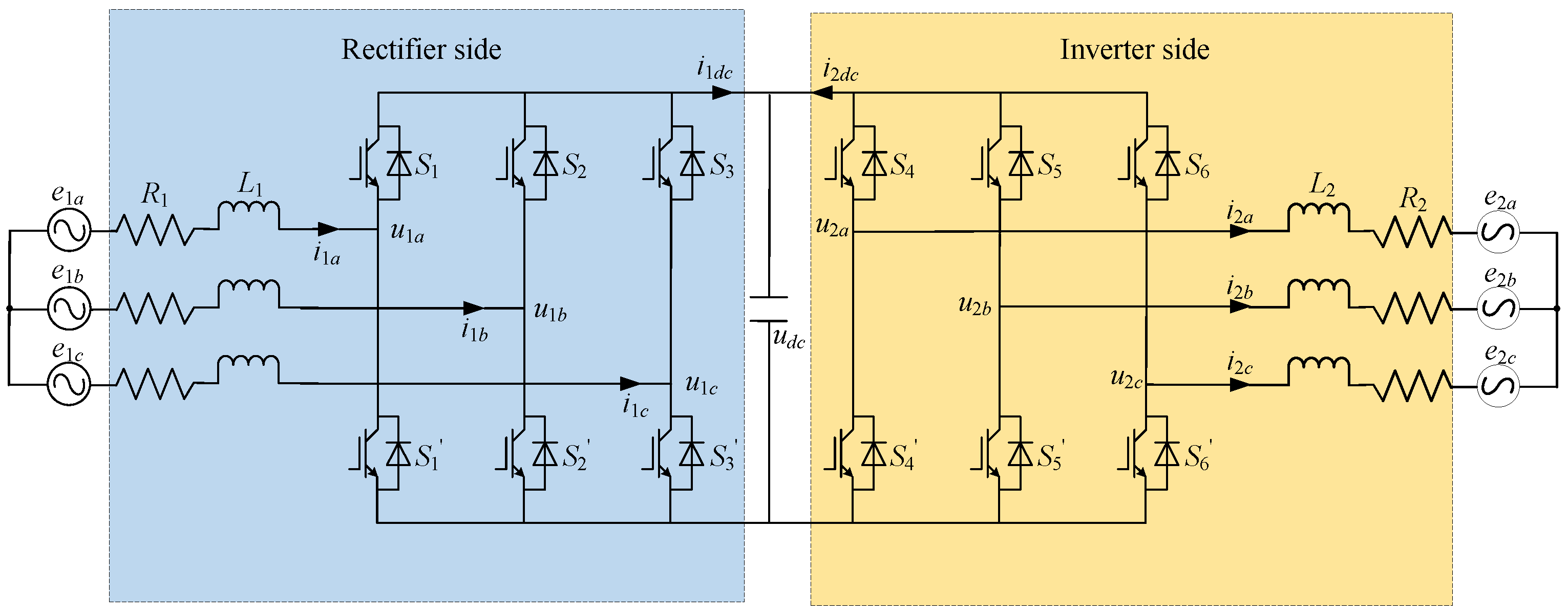
The structure of the two-port SOP is displayed in Figure 1 [32], where the rectifier side and the inverter side are interconnected by the capacitance of the DC side.
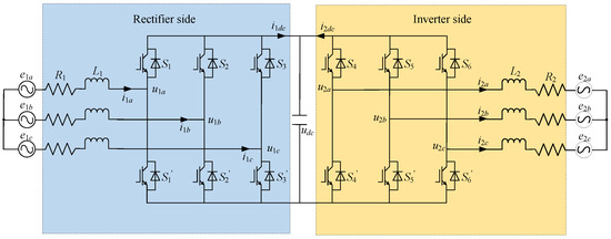
Figure 1.
Structure of the two-port SOP with the rectifier side and the inverter side.
The mathematical model of the rectifier side and the inverter side in the stationary coordinates can be obtained by
where e is the gird voltage, i the current, u the voltage, the subscript represents states in abc-axes, represents the input states from the rectifier side and the output states of the inverter side, and the inductance of the rectifier side and the inverter side, respectively, and the resistance of the rectifier side and the inverter side, respectively.
The switching states are defined as follows
Then, the voltages of each converter can be calculated by
where is the capacitor voltage of the DC link.
The current of the DC side in the d-q coordinates can be expressed as
where and are the currents in the DC side from the rectifer side and the inverter side, respectively, and the input currents of the rectifier side in d- and q-axes, respectively, and the output currents of the inverter side in d- and q-axes, respectively, and the switching states of the rectifier side in d- and q-axes, and the switching states of the inverter side in d- and q-axes.
Since the structure of each port of the SOP is the same, in this paper, one port of the VSC is selected to build the mathematical model. The dynamic mathematical model of the SOP in the d-q coordinates can be represented by
where is the rectifier-side current vector in d- and q-axes, the angular speed of the grid voltage, the rectifier-side voltage vector in d- and q-axes, the rectifier-side grid voltage vector in d- and q-axes.
2.2. Proposed Model of the SOP
2.2.1. Outer-Loop Subsystem
The outer-loop subsystem of the rectifier side in the SOP is the DC-side voltage control subsystem. The parameter variation results in the unmatched uncertainties in the outer-loop subsystem. The voltage controller uses as the input and as the output to establish the reference value of , which is designed to stabilize the DC-side voltage. According to the aforementioned mathematical model of the SOP, the tracking error dynamic of the DC-side voltage can be expressed by
Due to being adopted as the current control strategy, substituting the switching states and into the above, (7) can be rewritten as
Considering the variation of the parameters caused by the change of temperature and frequency in the SOP, the resistance, the inductance and the capacitance can be expressed by
where and represent the nominal and the changed value of the parameters.
The above parameter perturbations can be assumed to be bounded as follows
where , and are positive constants
Therefore, considering the parameter perturbation and the external disturbance, the error dynamics of the DC-side voltage can be rewritten as
where is the external disturbance which can be upper-bounded as .
The virtual control signal is defined as , where , and , the d-axis current tracking reference value can be calculated by .
Define the d-axis current tracking error as follows
To simplify the equation, let , where . Then, the tracking error dynamic of the DC-side voltage can be represented by
where is defined as the lumped unmatched uncertainty in the rectifier-side system of the SOP, +.
To analysis the lumped unmatched uncertainty , the following uncertainties are defined as
According to (10), the aforementioned uncertainties (14) can be upper-bounded as
where , , , , , and are positive constants.
Hence, the lumped unmatched uncertainty satisfies
where satisfies . The lumped unmatched uncertainty and its derivative are bounded by and .
2.2.2. Inner-Loop Subsystem
The inner-loop subsystem of the rectifier side in the SOP is the current-control subsystem. To ensure independent dynamic characteristics of the d-q currents, a feedforward compensation designed as is used to achieve dynamic decoupling and avoid the interaction effect of the coupled voltage.
There is no longer external disturbance but only parameter variation in the inner-loop subsystem, which belongs to the matched uncertainties. The current controllers use as the input and as the output to generate the SVPWM modulation signals. According to the aforementioned mathematical model of the SOP, the inner-loop subsystem can be obtained by
Considering the parameter variation, the inner-loop subsystem can be rewritten as
where , , and the lumped matched uncertainty and satisfies .
Introducing the feedforward compensation into (18) yields
where the lumped matched uncertainty and its derivative can be upper-bounded as and .
Lemma 1
([33]). Consider a system , , , if there exists a positive definite continuous function : , real numbers and , and an open neighborhood of the origin such that , , and then can approach zero in a finite-time, .
3. Full-Order Sliding-Mode Control for the Rectifier Side
Let and combine the outer-loop voltage subsystem and the decoupled inner-loop current subsystem, the mathematical model of the SOP can be summarized as a second-order system with matched and unmatched uncertainties in the following form.
where is the virtual control signal of the outer-loop subsystem.
In this section, a novel virtual-control-technique-based full-order sliding-mode controller is proposed for the rectifier side of the SOP. The virtual control signal is designed to deal with the unmatched uncertainties and force the DC-side voltage tracking error to converge to zero. In addition, the actual control signal is designed to compensate for the matched uncertainties and make the rectifier-side input current vector track its reference accurately.
3.1. Voltage Controller Design for the Outer-Loop
A full-order sliding-mode manifold is designed for the outer-loop subsystem with the form as follows
where is a positive constant.
Theorem 1.
If the sliding manifold is selected as (21) and the virtual control law ϕ is designed as follows, the outer-loop voltage-tracking error dynamics can be regulated to reach the ideal manifold in a finite time , thereafter remaining on it and converging to an equilibrium point asymptotically after the current tracking error and its derivative converge to zero.
where and are defined by (14a) and (16), is the upper bound of the derivative of the equivalent virtual control law (23), and is a positive constant.
Proof of Theorem 1
Substituting the error dynamic of the DC-side voltage (13) into the sliding manifold (21), yields
According to the designed virtual control law (22), the derivative of the sliding manifold can be represented by
defined by a Lyapunov function as . The derivative of can be obtained by
Substituting the integral-type switching-control law (24) into the above, gives
Then, the derivative of the Lyapunov function satisfies
where is the upper bound of .
If the switching gain satisfies , it yields
According to Theorem 2, the inner-loop tracking error and its derivative can be forced to converge to zero in finite time. Then, the above becomes
According to Lemma 1, if the current-tracking error and its derivative can converge to zero in finite time, the DC-side voltage tracking error dynamic will be forced to reach the ideal sliding manifold (21) in a finite time under the designed virtual control law (22). In addition, the system trajectory will converge to zero asymptotically along the sliding manifold. It is obvious that the integral-type control law can compensate for the unmatched uncertainties completely and make the control signal smooth. This completes the proof. □
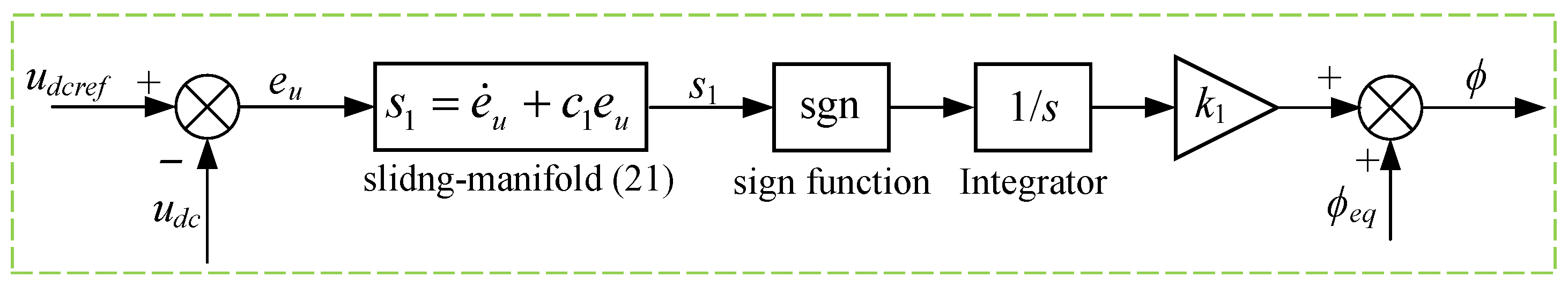
The calculation flowchart of the FOSMC is depicted in Figure 2.
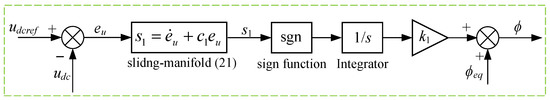
Figure 2.
Calculation flowchart of the full-order sliding-mode control method.
3.2. Current Controller Design for the Inner-Loop
The current tracking error is defined as . According to the current subsystem (), the error dynamic of the rectifier-side current can be obtained by
A full-order terminal sliding-mode manifold is designed for the inner-loop subsystem to have the form of [33]
where ; is the positive diagonal matrix, and are positive constants and q and p are odds and satisfy .
Theorem 2.
Based on the designed sliding surface (34), the virtual control law (22) and the following actual control law, the inner-loop current-tracking error dynamics can be regulated to reach the sliding surface in finite time . Then, the inner-loop tracking error and its derivative can converge to zero along the ideal sliding manifold in finite time [31].
where the known , , and are defined by (15), (16) and (19), respectively; represents the upper bound of the equivalent actual control signal , which satisfies ; and are assumed as the upper bound of the known function and its derivative, which satisfy , .
Proof of Theorem 2
Substituting the current tracking error dynamic (33) into the sliding manifold (34), yields
Considering the designed virtual control law (22), the above becomes
Substituting the actual control law (35) into the above, then we obtain
and the derivative of the sliding manifold (34) can be calculated by
We define a Lyapunov function as , and its derivative is expressed as
Substituting (37) into the above gives
assume , and , considering the upper bounds of the lumped uncertainties (16) and (19), the above becomes
If the switching gain satisfies , the derivative of the Lyapunov function satisfies
According to Lemma 1, the above means that the error dynamic can approach the ideal sliding manifold in a finite time . Thereafter, the tracking error of the rectifier-side input current and its derivative will converge to the equilibrium point in a finite time . This completes the proof. □
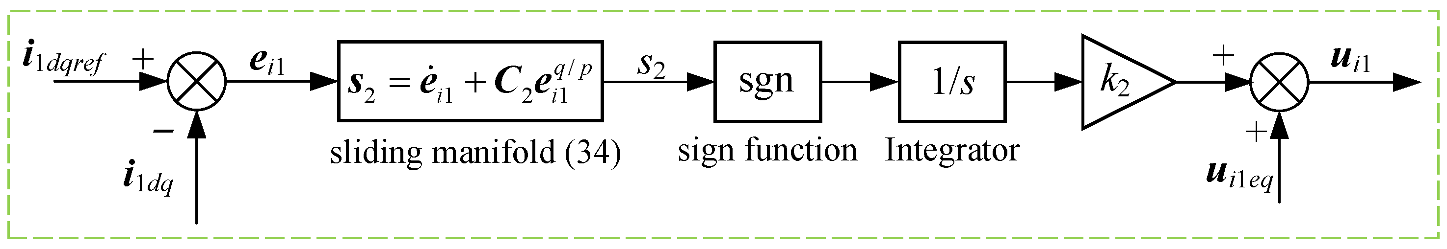
The calculation flowchart of the FOTSMC is depicted in Figure 3.
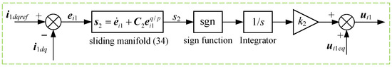
Figure 3.
Calculation flowchart of the full-order terminal sliding-mode control method.
4. Full-Order Sliding-Mode Control for the Inverter Side
The controller for the inverter side is designed to control the output active power and reactive power of the load power grid. The output active power and the reactive power of the inverter side in the d-q coordinates can be expressed by
where and are the inverter side grid voltages in the d- and q-axes, and the output currents of the inverter side in the d- and q-axes.
Aligning the voltage vector of the AC system with the d-axis of the rotating coordinate system, can be obtained, and is a constant, then
which illustrates that the power output from the inverter side to the grid can be controlled independently by controlling the inverter-side output currents and . Therefore, the design of the current controllers can refer to Theorem 2.
The tracking error of the output power can be defined as . According to the inner-loop subsystem (20), the error dynamic can be represented by
where , the decoupled control signal with the form as following
where is the external disturbance which can be upper-bounded as , and the lumped uncertainties , which satisfy . The lumped uncertainty and its derivative can be upper-bounded as and .
A full-order terminal sliding manifold is designed as follows
where is the positive diagonal matrix, and are positive constants q and p are odds and satisfy .
Theorem 3.
If the sliding manifold is selected as (50), the output-power-tracking error dynamics can approach the sliding manifold in finite time. The system trajectory will remain on sliding manifold and converge to zero under the designed control law as follows.
where the known and are defined by (14b) and (49), respectively, and represents the upper bound of the equivalent actual control signal , which satisfies .
Proof of Theorem 3
According to the output-power-tracking error dynamic (48), the sliding manifold (50) can be rewritten as
Substituting the control law (51) into the above, yields
Thus, the derivative of the sliding manifold (50) can be calculated by
We define a Lyapunov function as , and the derivative is
Substituting (53) into the above gives
assuming . Then, it can be obtained from the designed switching gain (54) that
which illustrates that the output-power-tracking error dynamic can be forced to reach the sliding manifold in a finite time. Thereafter, the system trajectory will converge to zero along the sliding manifold in finite time. This completes the proof. □
According to Theorems 1–3, the block diagram of the control scheme of the SOP is shown in Figure 4. The phase-locked loop (PLL) is used to obtain the angular speed of the grid voltage which is omitted here for space due to its simplicity.
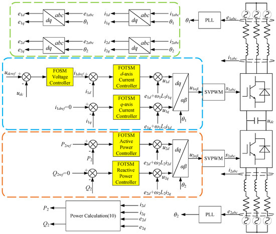
Figure 4.
Block diagram of the control scheme of the SOP.
5. Simulations
5.1. Empirical Research Methodology
To demonstrate the effectiveness of the proposed method under a serious condition, a model predictive control (MPC), a linear sliding-mode control (LSMC) and a full-order sliding-mode control (FOSMC) were used to design the controllers for performance comparison in MATLAB/Simulink. The parameters of the SOP are listed in Table 1 [14], and the controllers design parameters of the rectifier side and the inverter side are listed in Table 2 and Table 3, respectively.

Table 1.
The parameters of the SOP.
Table 2.
Controller design parameters for the rectifier side.
Table 3.
Controller design parameters for the inverter side.
5.2. Simulation Results
5.2.1. Start-up Response in the Case of Parameter Perturbation
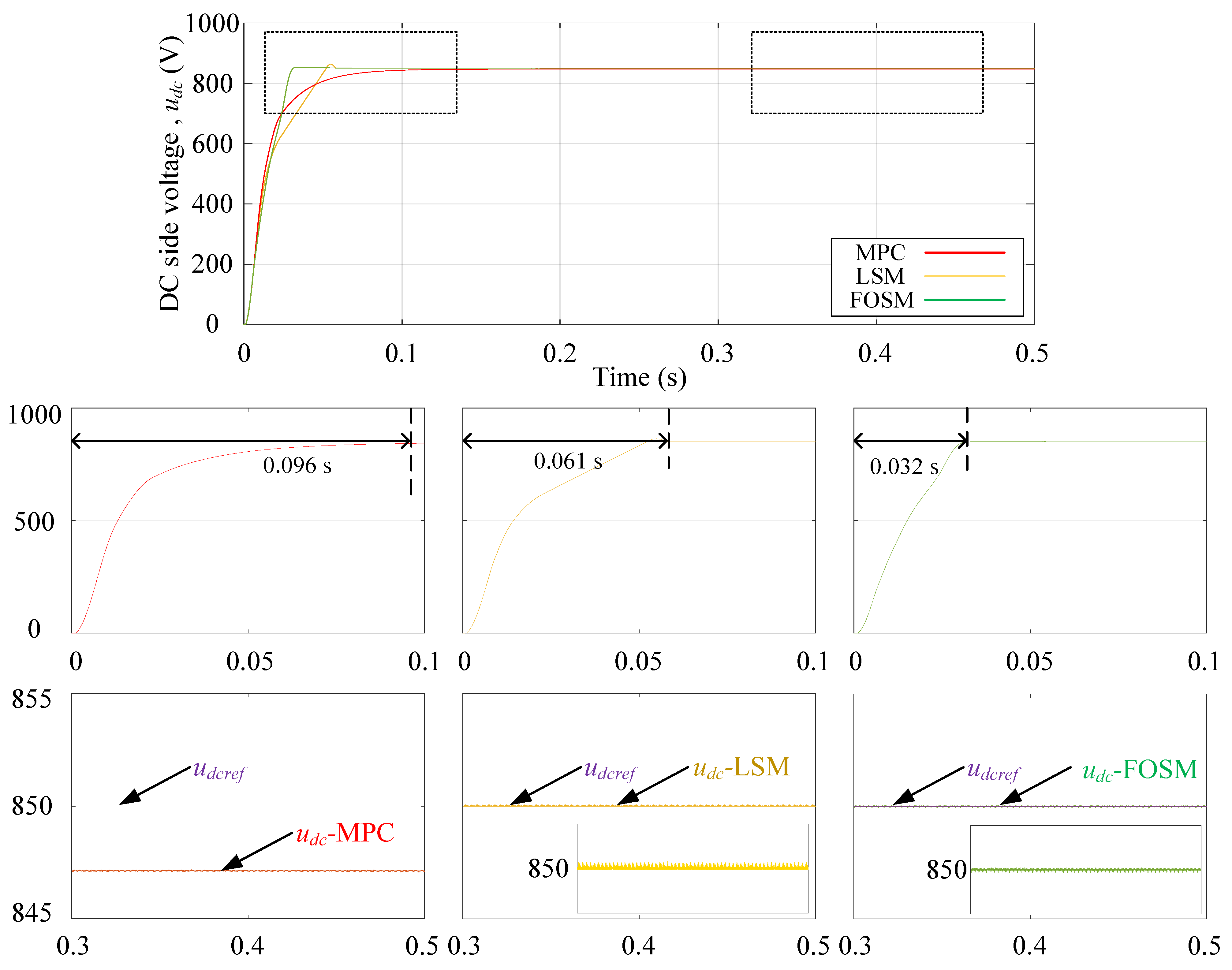
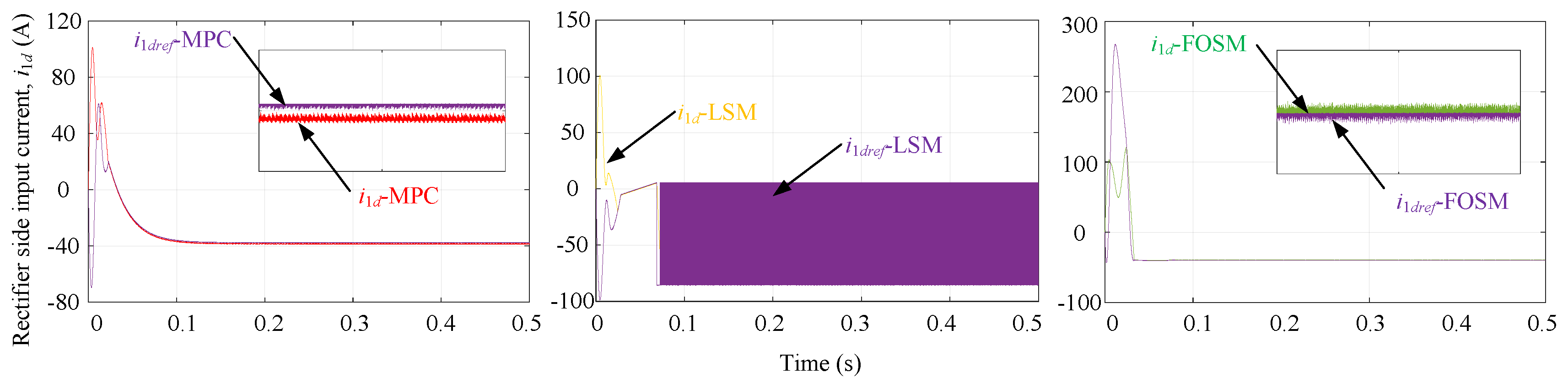
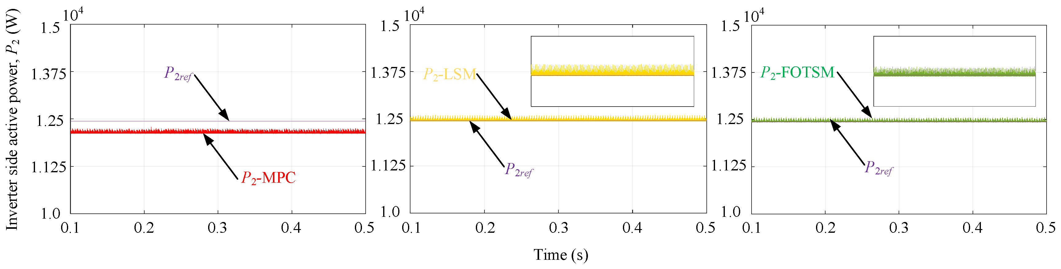
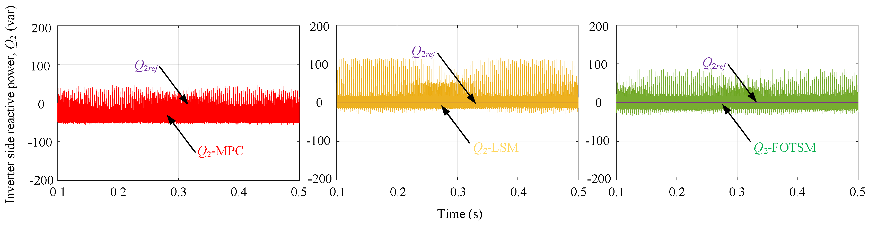
To characterize the parameter perturbation, the resistances and inductances in the rectifier and inverter sides are set to of the original value, and the capacitance in the DC side is set to of the original value. The simulation starts at 0 s and runs for 0.5 s in total. The reference value of the DC-side voltage and the load grid current are 850 V and 40 A, respectively. The DC-side voltage response under the the MPC, the LSM and the FOTSM controllers is depicted in Figure 5. It can be seen from Figure 5 that the settling time of the DC-side voltage under the MPC, the LSM and the FOTSM is s, s and s, respectively, which means that the proposed FTSM controller has the most rapid dynamic response. The DC-side voltage response under the MPC controller cannot be forced to reach the reference value and has a steady-state error of V. The MPC controller cannot satisfy the control requirements in the SOP. Figure 6 shows the d-axis current response in the rectifier side. The voltage response under the MPC controller fails to track the reference value in the case of parameter perturbation due to the controller’s characteristics of model dependance. This also results in the steady-state error in the DC-side voltage response. In Figure 5, it is obvious that the DC-side voltage response under the LSM and the FOSM tracks the reference value. This demonstrates that the two controllers can compensate for the uncertainties caused by the parameter perturbation. It can be seen from Figure 6 that the output of the LSM controller contains chattering, and the output of the FOSM controller is smooth thanks to the integral-type control law. The load grid active and reactive power responses are shown in Figure 7 and Figure 8. In the case of parameter perturbation, the MPC controllers cannot force the active and reactive power-tracking errors to converge to zero. It is evident that the ripple of the active and reactive power under the FOSM controller is smaller than the LSM controller in Figure 7 because of the integral-type control law and the adaptive switching gain.
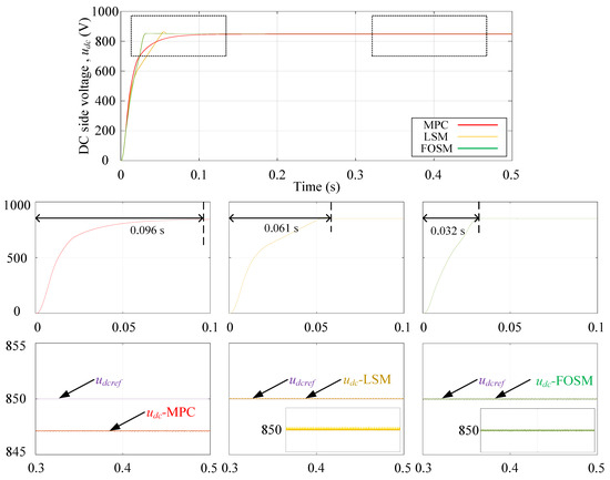
Figure 5.
The DC-side voltage responses under the MPC, the LSM and the FOSM.
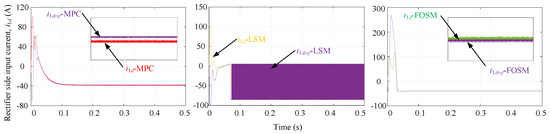
Figure 6.
Therectifier side d-axis current responses under the MPC, the LSM and the FOSM.
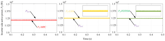
Figure 7.
The load grid active power responses under the MPC, the LSM and the FOTSM.

Figure 8.
Theload grid reactive power responses under the MPC, the LSM and the FOTSM.
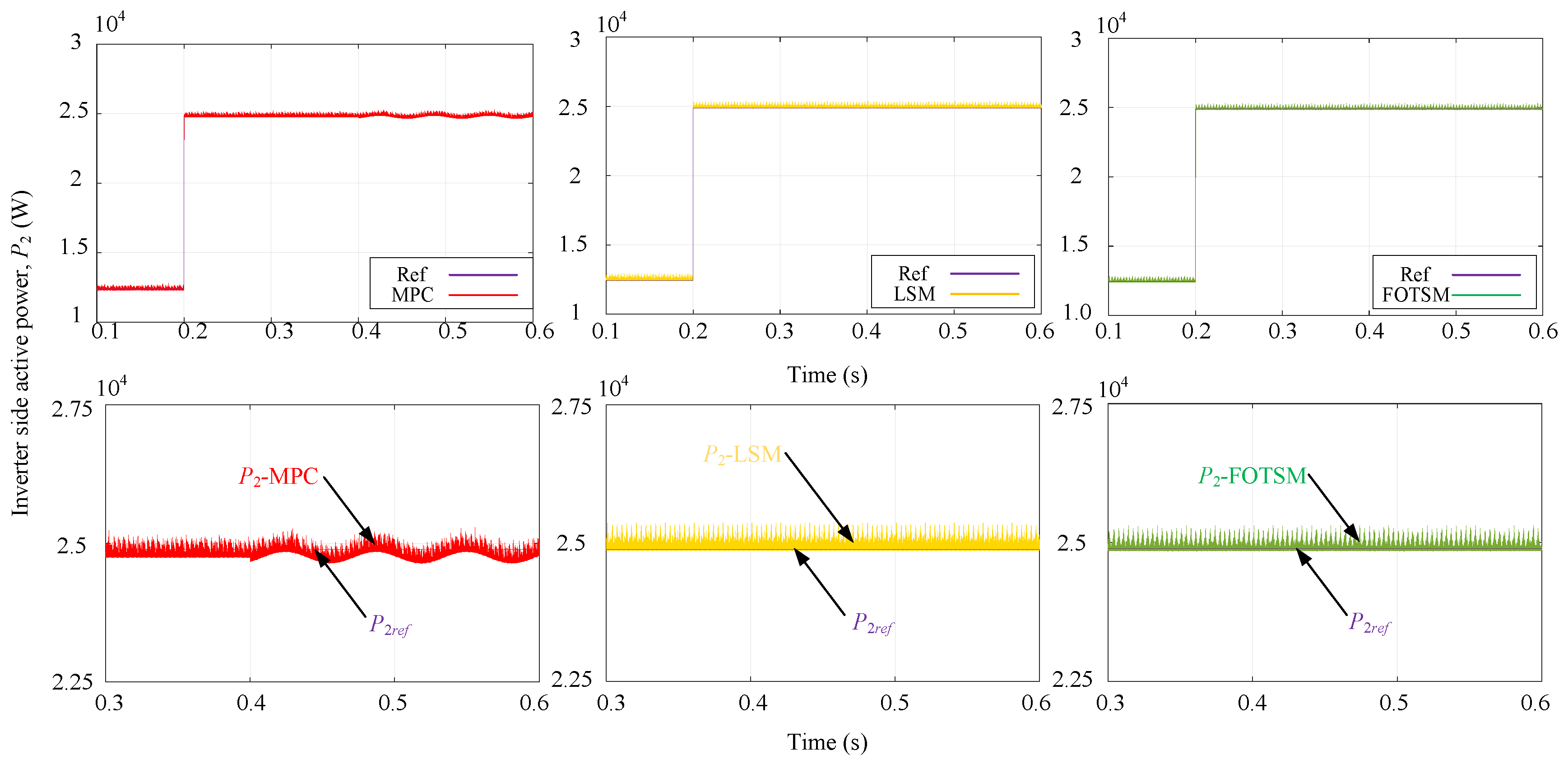
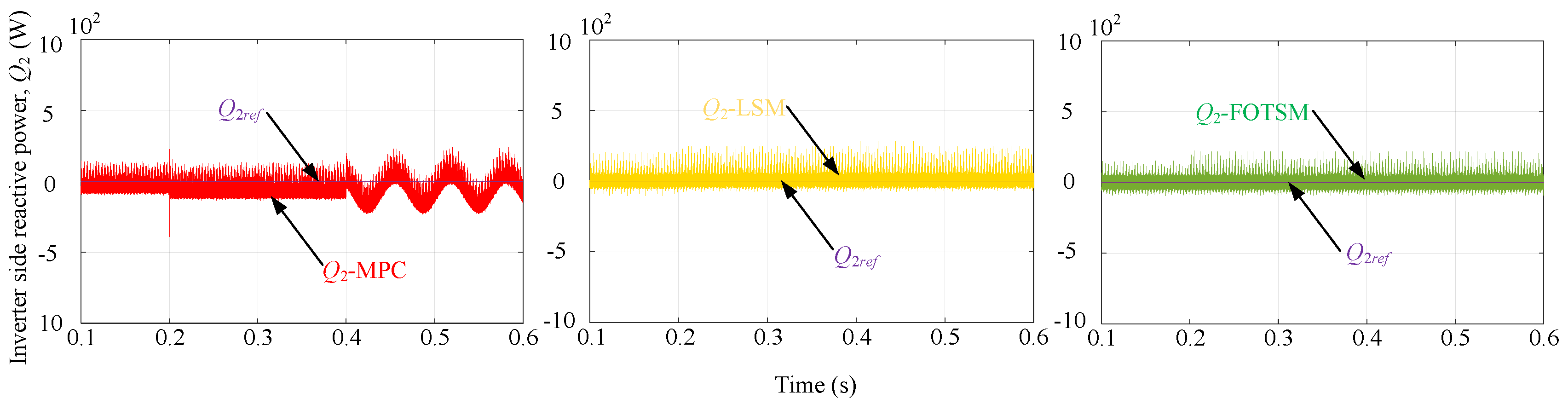
5.2.2. Load-Adding Response in the Case of External Disturbance
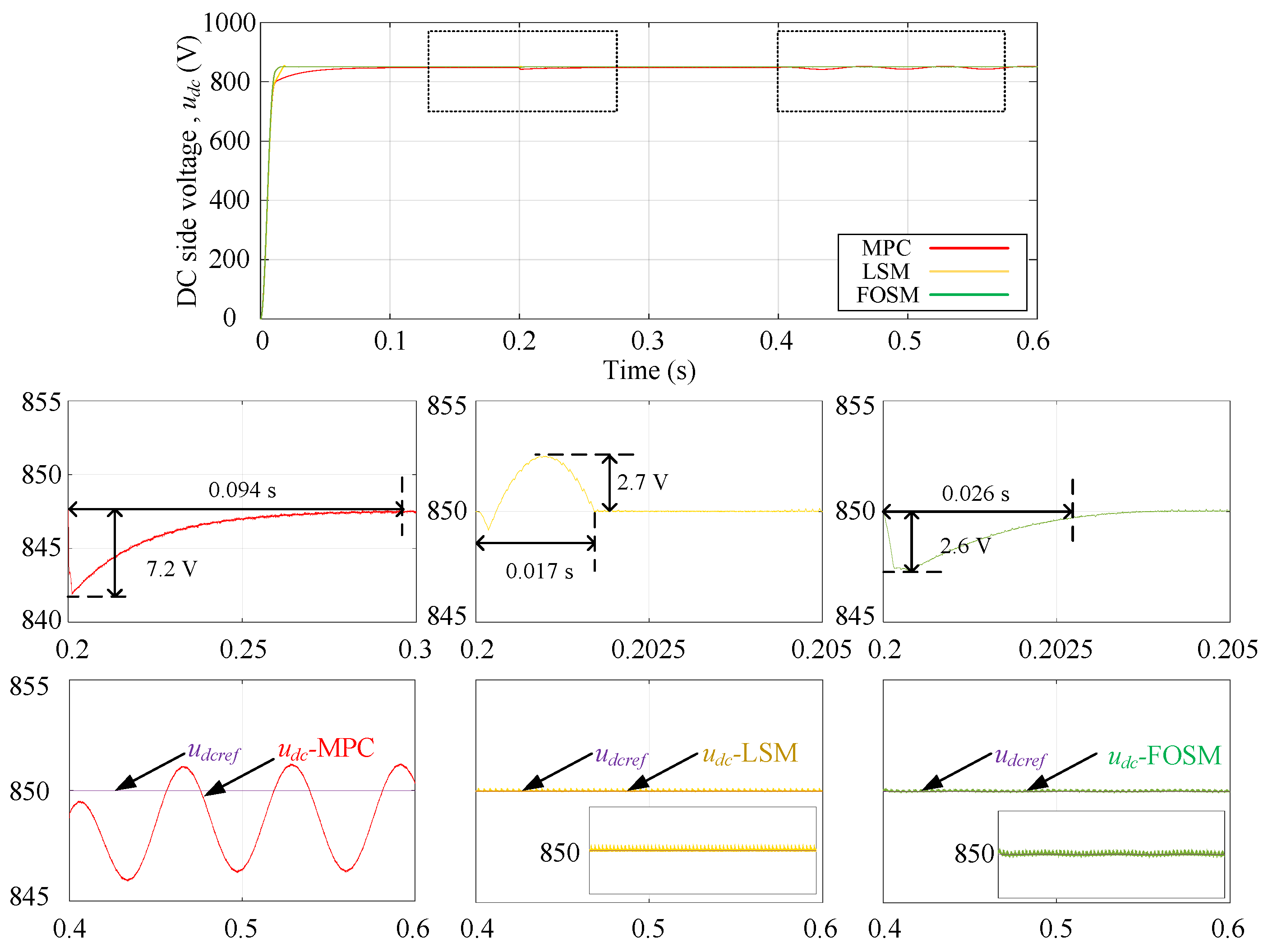
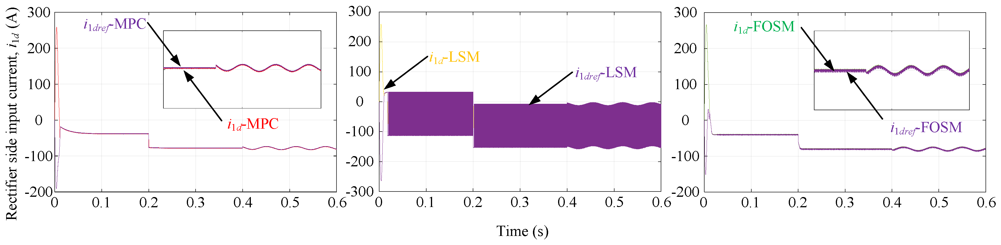
To attest the excellent dynamic performance and robustness of the proposed control method, the load grid current is changed from 40 A to 80 A at s, and the external disturbance and are added at s. The parameters of the resistances, inductances and capacitance are set to the original value. The simulation starts at 0 s and runs for s in total. From Figure 9, the setting time of the DC-side voltage response under the MPC, the LSM and the FOSM are s, s and s, respectively. Moreover, the DC-side voltage drop under the three control methods are V, V and V, which means that the proposed FOSM controller has a better dynamic performance in anti-disturbance and rapidness. After the external disturbance is added at s, it is obvious that the outer-loop PI controller cannot suffer the external disturbance in the form of sinusoid. The FOSM controller can deal with the added external disturbance and force the DC-side voltage-tracking error to converge to zero owing to the integral-type virtual control law. The LSM controller can also eliminate the external disturbance; however, the irreducible chattering exists in the control signal as shown in Figure 10. Figure 11 and Figure 12 show the load grid active and reactive power response under the three control methods. It can be seen that the MPC controller fails to deal with the sinusoidal disturbance , which results in the tracking error after the external disturbance is added at s. The LSM and FOTSM controllers compensate for the external disturbance completely and force the tracking error to converge to zero. However, the chattering still exists in the control law of the LSM and leads to a larger rippler than the FOTSM in the active and reactive power responses as shown in Figure 10 and Figure 11.
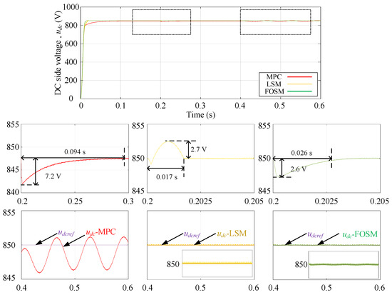
Figure 9.
The DC-side voltage responses under the MPC, the LSM and the FOTSM.
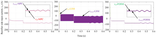
Figure 10.
Therectifier-side d-axis current responses under the MPC, the LSM and the FOTSM.
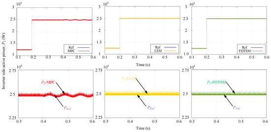
Figure 11.
The load grid active responses under the MPC, the LSM and the FOTSM.
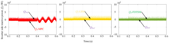
Figure 12.
The load grid reactive power responses under the MPC, the LSM and the FOTSM.
6. Discussion
In this paper, a full-order sliding-mode control algorithm is designed in -Q and P-Q working modes, and a corresponding simulation verification is carried out. However, the dynamic process of switching between different working modes is not taken into account. Combined with the dynamic process of the SOP, it will be the aim of a future work to verify the control effect of the proposed method in an electricity distribution network.
7. Conclusions
In this paper, a full-order terminal sliding-mode control theory is proposed to enhance the rapidness and robustness of the rectifier-side and the inverter-side controllers in a soft open point converter. The matched and unmatched uncertainties in the control system including external disturbances and parameter perturbation are considered in detail. The main contributions of the paper can be summarized as: (1) The proposed virtual-control-techinique-based full-order sliding-mode control method can improve the dynamic performance and anti-disturbance of the SOP control system with matched and unmatched uncertainties. (2) The integral-type control law eliminates the chattering and guarantees the current references and smooth responses. Finally, the simulations have demonstrated the effectiveness of the proposed full-order sliding-mode controllers.
Author Contributions
M.Z.: Conceptualization, algorithm innovation, methodology, writing and original draft; H.S.: data and formal analysis, investigation, software, simulation, writing and original draft. H.Z.: conceptualization, simulation, investigation, methodology, original draft; L.W.: investigation, review and editing; Y.L.: formal analysis, writing and editing; H.Y.: data and formal analysis, software, simulation. All authors have read and agreed to the published version of the manuscript.
Funding
This work is supported by the National Natural Science Foundation of China under Grant (62073095); by the National Key Research and Development Program of China (U21A20145); by the Heilongjiang Industrial Revitalization Major Project on Engineering and Science (2019ZX02A01).
Institutional Review Board Statement
Not applicable.
Informed Consent Statement
Not applicable.
Data Availability Statement
Data sharing not applicable.
Acknowledgments
This research was funded by New Energy Motor System and Key Materials Innovation Center in Harbin University of Science and Technology.
Conflicts of Interest
The authors declare no conflict of interest. The funders had no role in the design of the study; in the collection, analyzes, or interpretation of data; in the writing of the manuscript; nor in the decision to publish the results.
Abbreviations
The following abbreviations are used in this manuscript:
| SOP | Soft open point |
| VSC | Voltage source converter |
| AC | Alternating current |
| DC | Direct current |
| LSM | Linear sliding-mode |
| FOTSM | Full-order terminal sliding-mode |
| FOSM | Full-order sliding-mode |
| PI | Practical proportional-integral |
| MPC | Model predictive control |
| SMC | Sliding-mode control |
| ISMC | Integral sliding-mode control |
| DOBSMC | Disturbance observer-based sliding-mode control |
| SVPWM | Signals of space vector pulse width modulation |
| PLL | Phase look loop |
References
- Jiang, X.; Zhou, Y.; Ming, W.; Yang, P.; Wu, J. An Overview of Soft Open Points in Electricity Distribution Networks. IEEE Trans. Smart Grid 2022, 13, 1899–1910. [Google Scholar] [CrossRef]
- Liu, Z.; Wang, L. A Robust Strategy for Leveraging Soft Open Points to Mitigate Load Altering Attacks. IEEE Trans. Smart Grid 2022, 13, 1555–1569. [Google Scholar] [CrossRef]
- Sun, F.; Ma, J.; Yu, M.; Wei, W. Optimized Two-Time Scale Robust Dispatching Method for the Multi-Terminal Soft Open Point in Unbalanced Active Distribution Networks. IEEE Trans. Sustain. Energy 2021, 12, 587–598. [Google Scholar] [CrossRef]
- Wang, J.; Zhou, N.; Chung, C.Y.; Wang, Q. Coordinated Planning of Converter-Based DG Units and Soft Open Points Incorporating Active Management in Unbalanced Distribution Networks. IEEE Trans. Sustain. Energy 2020, 11, 2015–2027. [Google Scholar] [CrossRef]
- Ding, T.; Wang, Z.; Jia, W.; Chen, B.; Chen, C.; Shahidehpour, M. Multiperiod Distribution System Restoration With Routing Repair Crews, Mobile Electric Vehicles, and Soft-Open-Point Networked Microgrids. IEEE Trans. Smart Grid 2020, 11, 4795–4808. [Google Scholar] [CrossRef]
- Ji, H.; Wang, C.; Li, P.; Ding, F.; Wu, J. Robust Operation of Soft Open Points in Active Distribution Networks With High Penetration of Photovoltaic Integration. IEEE Trans. Sustain. Energy 2019, 10, 280–289. [Google Scholar] [CrossRef]
- Ouyang, S.; Liu, J.; Yang, Y.; Chen, X.; Song, S.; Wu, H. DC Voltage Control Strategy of Three-Terminal Medium-Voltage Power Electronic Transformer-Based Soft Normally Open Points. IEEE Trans. Ind. Electron. 2020, 67, 3684–3695. [Google Scholar] [CrossRef]
- Yang, X.; Xu, C.; Zhang, Y.; Yao, W.; Wen, J.; Cheng, S. Real-Time Coordinated Scheduling for ADNs With Soft Open Points and Charging Stations. IEEE Trans. Power Syst. 2021, 36, 5486–5499. [Google Scholar] [CrossRef]
- Liang, X.; Saaklayen, M.A.; Igder, M.A.; Shawon, S.M.R.H.; Faried, S.O.; Janbakhsh, M. Planning and Service Restoration Through Microgrid Formation and Soft Open Points for Distribution Network Modernization: A Review. IEEE Trans. Ind. Appl. 2022, 36, 1843–1857. [Google Scholar] [CrossRef]
- Huo, Y.; Li, P.; Ji, H.; Yan, J.; Song, G.; Wu, J.; Wang, C. Data-Driven Adaptive Operation of Soft Open Points in Active Distribution Networks. IEEE Trans. Ind. Appl. 2021, 17, 8230–8242. [Google Scholar] [CrossRef]
- Zheng, L.; Kandula, R.P.; Divan, D. Robust Predictive Control for Modular Solid-State Transformer With Reduced DC Link and Parameter Mismatch. IEEE Trans. Power Electron. 2021, 36, 14295–14311. [Google Scholar] [CrossRef]
- Zhang, Z.; Fang, H.; Gao, F.; Rodríguez, J.; Kennel, R. Multiple-Vector Model Predictive Power Control for Grid-Tied Wind Turbine System With Enhanced Steady-State Control Performance. IEEE Trans. Power Electron. 2017, 64, 6287–6298. [Google Scholar] [CrossRef]
- Pamshetti, V.B.; Singh, S.; Thakur, A.K.; Singh, S.P. Multistage Coordination Volt/VAR Control With CVR in Active Distribution Network in Presence of Inverter-Based DG Units and Soft Open Points. IEEE Trans. Ind. Appl. 2021, 57, 2035–2047. [Google Scholar] [CrossRef]
- Wang, Z.; Zhou, H.; Huo, Q.; Hao, S. Three-Vector-Based Low Complexity Model Predictive Control for Soft Open Point. Math. Probl. Eng. 2022, 2022, 1526676. [Google Scholar] [CrossRef]
- Ivic, D.R.; Stefanov, P.C. An Extended Control Strategy for Weakly Meshed Distribution Networks With Soft Open Points and Distributed Generation. IEEE Access 2021, 9, 137886–137901. [Google Scholar] [CrossRef]
- Sarantakos, I.; Zografou-Barredo, N.-M.; Huo, D.; Greenwood, D. A Reliability-Based Method to Quantify the Capacity Value of Soft Open Points in Distribution Networks. IEEE Trans. Power Syst. 2021, 36, 5032–5043. [Google Scholar] [CrossRef]
- Jia, L.; Lakshmikanthan, S.; Li, X.; Liu, Y. New Modeling Method and Design Optimization for a Soft-Switched DC–DC Converter. IEEE Trans. Power Electron. 2018, 33, 5754–5772. [Google Scholar] [CrossRef]
- Fuad, K.S.; Hafezi, H.; Kauhaniemim, K.; Laaksonen, H. Soft Open Point in Distribution Networks. IEEE Access 2020, 8, 210550–210565. [Google Scholar] [CrossRef]
- Li, B.; Liang, Y.; Wang, G.; Li, H.; Ding, J. A control strategy for soft open points based on adaptive voltage droop outer-loop control and sliding mode inner-loop control with feedback linearization. Int. J. Electr. Power Energy Syst. 2020, 122, 106205. [Google Scholar] [CrossRef]
- Repecho, V.; Biel, D.; Olm, J.M.; Fossas, E. Robust sliding mode control of a DC/DC Boost converter with switching frequency regulation. J. Frankl. Inst. 2018, 355, 5367–5383. [Google Scholar] [CrossRef]
- Liu, X.; Shan, Z.; Li, Y. Dynamic boundary layer based neural network quasi-sliding mode control for soft touching down on asteroid. Adv. Space Res. 2017, 59, 2173–2185. [Google Scholar] [CrossRef]
- Kumar, V.; Mohanty, S.R.; Kumar, S. Event Trigger Super Twisting Sliding Mode Control for DC Micro Grid With Matched/Unmatched Disturbance Observer. IEEE Trans. Smart Grid 2020, 11, 3837–3849. [Google Scholar] [CrossRef]
- Zheng, X.; Li, P.; Li, H.; Ding, D. Adaptive backstepping-based NTSM control for unmatched uncertain nonlinear systems. J. Syst. Eng. Electron. 2015, 26, 557–564. [Google Scholar] [CrossRef]
- Sánchez, B.; Cuvas, C.; Ordaz, P.; Santos-Sánchez, O.; Poznyak, A. Full-Order Observer for a Class of Nonlinear Systems With Unmatched Uncertainties: Joint Attractive Ellipsoid and Sliding Mode Concepts. IEEE Trans. Ind. Electron. 2020, 67, 5677–5686. [Google Scholar] [CrossRef]
- Zhang, Y.; Zhang, Q.; Zhang, J.; Wang, Y. liding Mode Control for Fuzzy Singular Systems With Time Delay Based on Vector Integral Sliding Mode Surface. IEEE Trans. Fuzzy Syst. 2020, 28, 768–782. [Google Scholar] [CrossRef]
- Elkayam, M.; Kolesnik, S.; Kuperman, A. Guidelines to Classical Frequency-Domain Disturbance Observer Redesign for Enhanced Rejection of Periodic Uncertainties and Disturbances. IEEE Trans. Power Electron. 2019, 34, 3986–3995. [Google Scholar] [CrossRef]
- Yueneng, Y.; Ye, Y. Backstepping sliding mode control for uncertain strict-feedback nonlinear systems using neural-network-based adaptive gain scheduling. J. Syst. Eng. Electron. 2018, 34, 580–586. [Google Scholar]
- Rubagotti, M.; Estrada, A.; Castanos, F.; Ferrara, A.; Fridman, L. Integral Sliding Mode Control for Nonlinear Systems With Matched and Unmatched Perturbations. J. Syst. Eng. Electron. 2011, 56, 2699–2704. [Google Scholar] [CrossRef]
- Yang, J.; Li, S.; Yu, X. Sliding-Mode Control for Systems With Mismatched Uncertainties via a Disturbance Observer. IEEE Trans. Ind. Electron. 2013, 60, 160–169. [Google Scholar] [CrossRef]
- Ding, Z. Consensus Disturbance Rejection With Disturbance Observers. IEEE Trans. Ind. Electron. 2015, 62, 5829–5837. [Google Scholar] [CrossRef]
- Feng, Y.; Zhou, M.; Zheng, X.; Han, F.; Yu, X. Full-order Terminal Ssliding-mode Control of MIMO Systems with Unmatched Uncertainties. J. Frankl. Inst. 2018, 335, 653–674. [Google Scholar] [CrossRef]
- Wang, Z.; Sheng, L.; Huo, Q.; Hao, S. An Improved Model Predictive Control Method for Three-Port Soft Open Point. Math. Probl. Eng. 2021, 2021, 9910451. [Google Scholar] [CrossRef]
- Feng, Y.; Han, F.; Yu, X. Chattering Free Full-order Slidng-mode Control. Automatica 2014, 50, 1310–1314. [Google Scholar] [CrossRef]

Publisher’s Note: MDPI stays neutral with regard to jurisdictional claims in published maps and institutional affiliations. |
© 2022 by the authors. Licensee MDPI, Basel, Switzerland. This article is an open access article distributed under the terms and conditions of the Creative Commons Attribution (CC BY) license (https://creativecommons.org/licenses/by/4.0/).