Article

Seepage Law of Nearly Flat Coal Seam Based on Three-Dimensional Structure of Borehole and the Deep Soft Rock Roadway Intersection

1
College of Energy Engineering, Xi’an University of Science and Technology, Xi’an 710054, China
2
Shaanxi Shanmei Huangling Mining Group Co., Ltd., Yan’an 727307, China
3
College of Safety Science and Engineering, Xi’an University of Science and Technology, Xi’an 710054, China
4
Information Research Institute of the Ministry of Emergency Management, Beijing 100029, China
*
Author to whom correspondence should be addressed.
Energies 2022, 15(14), 5012; https://doi.org/10.3390/en15145012
Submission received: 23 May 2022 / Revised: 1 July 2022 / Accepted: 7 July 2022 / Published: 8 July 2022

Abstract

:
Exploring the evolution characteristics of gas seepage between boreholes during the drainage process is critical for the borehole’s layout and high-efficiency gas drainage. Based on the dual-porous medium assumption and considering the effect of stress redistribution on coal seam gas seepage characteristics, a coal seam gas seepage model with a three-dimensional roadway and borehole crossing structure has been established and numerically calculated, concluding that the coal seam is between the drainage boreholes. The temporal and spatial evolution characteristics of gas pressure and permeability help elucidate the gas seepage law of the nearly flat coal seam associated with the deep soft rock roadway and borehole intersection model. The results indicate that: (1) The roadway excavation results in localized stress in some areas of the surrounding rock, reducing the strength of the coal body, increasing the expansion stress, and increasing the adsorption of gas by the coal body. (2) Along the direction of the coal seam, the permeability decreases initially and then increases. The gas pressure in the coal seam area in the middle of the borehole is higher than the pressure in the coal seam around the borehole, and the expansion stress and deformation increase, reducing the permeability of the coal body; when near the next borehole, the greater the negative pressure, the faster the desorption of the gas attracts the matrix shrinkage effect and causes the coal seam permeability rate to keep increasing. (3) The improvement of gas drainage with the overlapping arrangement of two boreholes firstly increases and then decreases as time goes on. (4) When the field test results and numerical simulation of the effective area of gas extraction are compared, the effectiveness of the model is verified. Taking the change of the porosity and the permeability into the model, it is able to calculate the radius of gas drainage more accurately.

1. Introduction

Gas drainage is the major approach for mine gas prevention and control. The drainage of gas boreholes efficiently is critical for mine gas control [1]. To optimize high-efficiency gas drainage, the coal seam permeability must be increased, allowing for gas to flow to the boreholes and enter the drainage system under negative pressure [2]. In order to increase the efficiency of gas drainage, the coupling model of coal seam deformation and gas seepage was established [3]. It was suggested that borehole drainage efficiency and coal seam permeability are inextricably linked [4]. At the moment, one of the primary factors affecting coal seam permeability is the local stress concentration of coal rock caused by engineering disturbance [5,6]. The gas seepage equation of the low-permeability outburst coal seam was proposed, and the permeability of raw coal was calculated, which is in good agreement with the field-measured data [7]. Numerical calculations on the gas flow field surrounding a two-dimensional gas drainage borehole were carried out and found that both the gas pressure and fracture permeability distribution were “8-shaped” [8]. When the stress environment of the coal body changes, the permeability varies as well, affecting the drainage efficiency of borehole gas [9,10,11]. However, their relationship is complex, poorly connected, and susceptible to changes in a borehole with-in external stress conditions. So, the study of the “stress-permeability” mechanism of a borehole structure will become particularly important [12,13,14]. Except for the stress, the structure of the coal seam also has a great effect on the permeability. A coupled coal and gas flow model with the dual medium characteristics of coal was established to improve the permeability [15]. However, the shortcoming of traditional empirical equations was pointed out and suggested that we should pay more attention to the evolution of the coal seam pore structure [16] and the matrix expansion [17,18] during the methane extraction process. Another feature that we cannot neglect is the Klinkenberg effect, which needs to be considered in the relationship between porosity and gas pressure [19]. Besides, according to the hysteresis of reversible permeability with the relationship between the desorption rate and the development of coal fractures, a gas outburst model was proposed [20]. Following that, a simulating of the change process of permeability and strain was performed to verify the hysteresis [21].
The aforementioned theories are vital for guiding the development of mine gas drainage projects. These studies serve as a foundation for an in-depth examination of the effect of coal seam gas seepage on drilling efficiency. However, because most of their research focuses exclusively on in-situ stress, they overlook the critical factor of the surrounding rock stress redistribution induced by roadway drainage. The majority of their models are two-dimensional, resulting in discrepancies between the model and the field.
Thus, based on the premise of the stress redistribution in the surrounding rock space caused by the drainage process, this paper proposes a three-dimensional intersection model of a roadway and a gas drainage borehole. With the assumption of dual porous media and the near-real stress distribution of the surrounding rock after roadway excavations and considering the coal-rock stress concentration factors, a multi-field coupled seepage model between the tunnel and borehole has been established. This model includes the effective stress, matrix shrinkage, Klinkenberg effect stress field, and desorption-diffusion mass source exchange field. The objective is to determine the temporal and spatial evolution characteristics of coal seam gas pressure and permeability between boreholes during the gas drainage process, as well as the temporal and spatial distribution characteristics of effective drainage areas at various borehole positions, to acknowledge the coal seam gas seepage law and to strengthen scientific gas drainage.

2. Materials and Methods

Huangling No.1 Coal Mine, located northwest of Diantou town, belongs to Huangling county of the Shannxi Province [22]. The average buried depth of the coal seam is 350 m, and the mining depth is about 312~417 m. The roof of the coal seam is sandstone and mudstone interbedded, and the floor is mudstone. The dip angle of the coal seam is 3°~5°, which can be regarded as a flat seam. The mechanical model of the borehole and roadway intersection is shown in Figure 1.
The formation of the three-dimensional spatial structure at the intersection of the gas drainage borehole and the roadway is divided into two steps: the first step is to subject the coal seam to in-situ stress and then redistribute the spatial stress of the surrounding rock via the excavation roadway; the second step is to drill a drainage hole in the surrounding rock coal seam to redistribute the stress. The roadway excavation is bound to break the original stress field equilibrium and results in an imbalanced gas pressure field. During the readjustment of the internal space stress of the surrounding rock, stress concentration occurs in local areas. Figure 2 depicts the stress distribution affecting the gas drainage borehole, namely the three-dimensional spatial structure of the intersection of the gas drainage borehole and the roadway, forming a stress reduction area, a stress concentration area, and an original rock stress area. These three areas of stress correspond to the stress distribution presented in [23].
One of the cores of studying coal and gas outbursts is to pay close attention to the stress state of the coal seam [21,24]. When the coal seam is located above the original in-situ stress, regeneration cracks and plastic deformation occur. Based on the assumption of dual porous media, the equivalent effective stress of gas-bearing coal under the combined action of external stress, pore gas pressure, and expansion stress can be expressed as:
σ i j e = σ i j ( β f p f + β m p m + σ a ) δ i j P w
where σ i j e is the effective stress, MPa; σ i j is the external stress of the coal body, MPa; pf and pm are, respectively, the gas pressures in the fractures and pores of the coal body, MPa; δij is the Kronecker delta tensor; βf and βm are the Biot effective stress coefficients of cracks and pores, respectively, and σa is the adsorption expansion stress. Equation (1) also can be expressed as:
σ i j e = σ i j P w
where Pw is the sum of the pore-crack gas pressure and expansion stress.
According to the Mohr–Coulomb strength theory, the shear failure strength condition of a gas-containing coal body is:
| τ f | = τ 0 + σ i j e tan φ
where τ0 is the internal friction force of gas-containing coal; φ is the internal friction angle of gas-containing coal.
After applying the equivalent effective stress, the center position and the stress circle radius of Mohr’s circle are:
σ i j e = 1 2 ( σ i j 1 + σ i j 2 ) = 1 2 ( σ 1 + σ 3 ) P w = σ m P w
τ i j m = 1 2 ( σ i j 1 σ i j 2 ) = 1 2 ( σ 1 σ 2 ) = τ m
As seen in Figure 3, the size of the molar stress circle remains constant when the coal seam contains gas, but the coordinates of the center of the circle move to the left by Pw. It demonstrates that the stress intensity of a gas-containing coal is reduced Indeed, the roadway disturbance produces areas of high-stress concentration, where the coal strength decreases more obviously, the expansion stress (pore pressure) increases, and the coal absorbs more gas, which is also a key area for coal and gas outburst accidents [25].

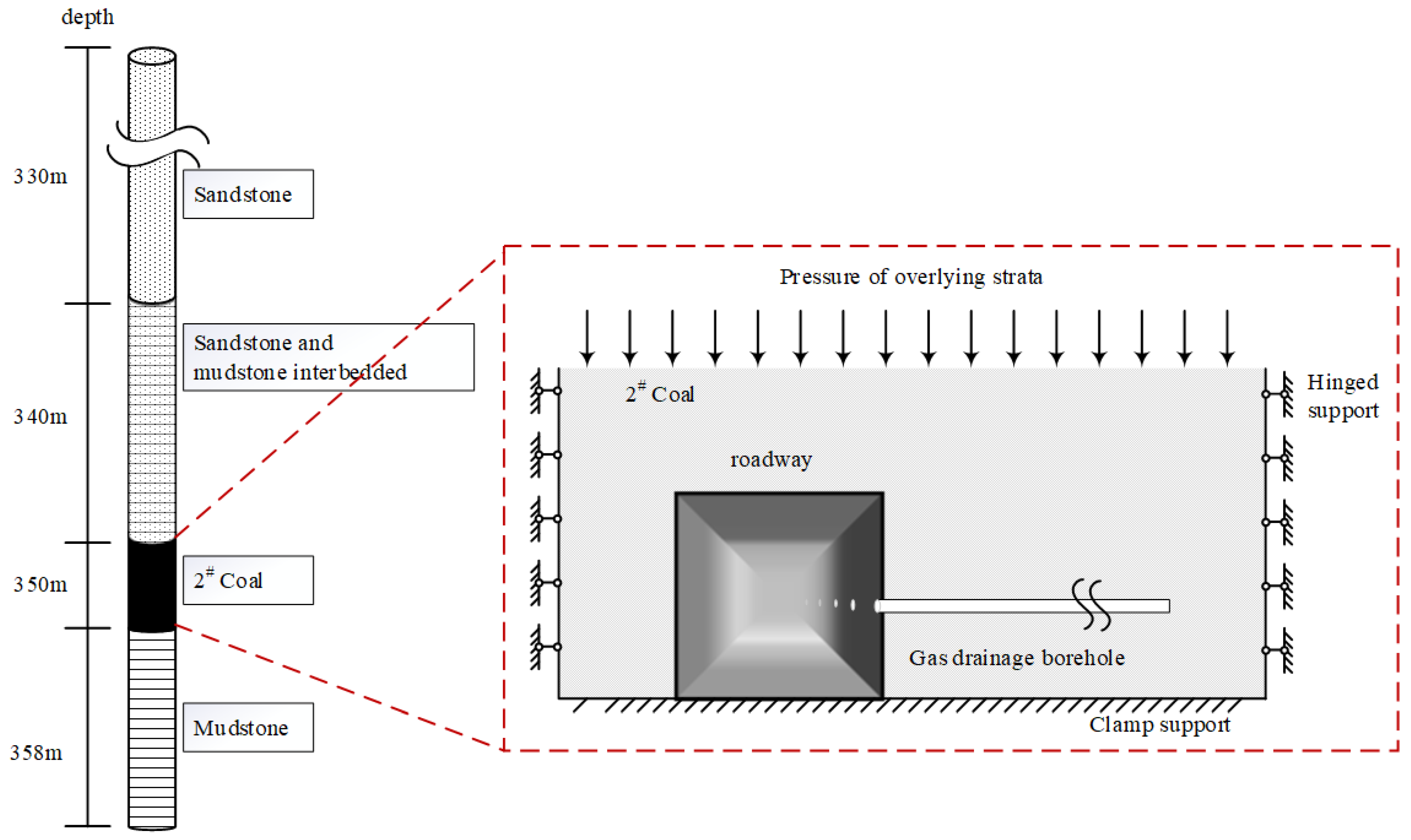
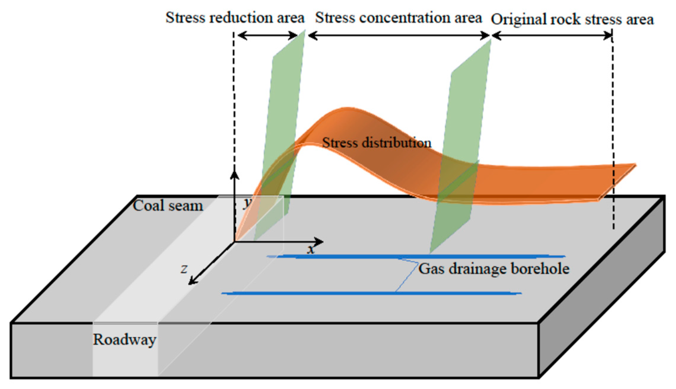
2.1. Gas–Solid Coupling Physical Model of the Gas-Bearing Coalbed

The gas migration pattern in the coal seam is highly dependent on its pore structure, and the pore-fracture dual medium model regards the coal seam gas migration process as a series relationship [15].
Migration process: First, the gas diffuses into the fractures, and then the gas seeps into the drainage boreholes or roadways via the fractures, completing the diffusion process into the seepage. The coal seam gas migration process is shown in Figure 4.

2.2. Principle of Effective Stress of the Gas-Bearing Coal Body

The effective stress equation of the gas-bearing coal body is shown in Equation (1), where σa is the adsorption expansion stress [26], which can be obtained from the following formula:
σ a = a ρ s R T ln ( 1 + b p p ) V m
where a is the limit adsorption capacity, cm3/g; ρs is the true density of coal, kg/m3; R is the gas constant, of which the value is 8.3143 J/(mol*K); T is the temperature, K; b is the adsorption equilibrium constant, MPa−1; Vm is the gas molar volume, the value of which is 22.4 L/mol.
The deformation equation of a gas-bearing coal rock consists of three parts: the stress balance equation, geometric equation, and constitutive equation:
(1) According to the law of conservation of momentum for multiple media, the equilibrium equation is:
σ i j , j + F i = 0
(2) The geometric equation of gas-bearing coal rock is:
ε i j = 1 2 ( μ i , j μ j , i )
where εij is the strain tensor; μj,i and μi,j are the displacement tensors.
The tensor form is:
ε i j = 1 + μ E σ i j + μ E σ ν δ i j
According to the generalized Hooke’s law:
σ i j = 2 G ε i j + 2 G ν 1 2 ν ε v δ i j
By associating (8) with (10), we can obtain the linear elastic deformation equation in Navier for the coal body, considering the mechanical effect of the pore pressure and adsorption effect, as shown in Equation (11):
2 G ε i j + 2 G ν 1 2 ν ε v δ i j β f p f β m p m σ a + F i = 0
where G is the shear modulus, MPa; ν is Poisson’s ratio; εV is the volumetric strain; Fi is the volume force, MPa.

2.3. Dynamic Evolution Equations of Coal Porosity and Permeability

From the previous research [27] considering effective stress and matrix shrinkage, a theory based on single pore–pore elasticity was established, in which the change of the fracture pore with effective stress satisfies the following conditions:
d ϕ f = [ 1 M ( 1 ϕ f ) f γ ] ( d σ β d p ) + [ K M ( 1 ϕ f ) ] γ d p [ K M ( 1 ϕ f ) ] α t d T
where f is the proportional coefficient, ranging from 0 to 1; γ is the skeleton compression coefficient (Pa−1); αt is the skeleton thermal expansion coefficient (F-1); M is the restrained axial modulus (MPa); Φf is the crack porosity (%); p is the coal seam gas pressure (MPa); β is the effective stress coefficient; T is the coal seam temperature (K). For coal with a pore-crack dual medium, it is necessary to calculate the change of the fracture porosity with effective stress by solving, namely,
d ϕ f = 1 M ( d σ β f d p f β m d p m d σ a ) ( 1 ϕ f ) f γ ( d σ β f d p f β m d p m d σ a ) + [ K M ( 1 ϕ f ) ] γ ( β f d p f β m d p m d σ a ) [ K M ( 1 ϕ f ) ] α t d T
The fracture porosity of the coal body is Φf << 1. Although the coal body is disturbed by the roadway and top load, it is in a state of equilibrium, that is, = 0. At the same time, the coal matrix is incompressible, as γ = 0 [15], which yields:
α d T = d d p m ( ε L p m p m + P L ) d p m
where εL is the limit adsorption expansion deformation of the coal body; PL is the Langmuir pressure constant (MPa); then, Equation (13) can be simplified as:
d ϕ f = 1 M ( β f d p f + β m d p m + d σ a ) ( K M 1 ) d d p m ( ε L p m p m + P L ) d p m
Expand and reorganize Equation (15) into the full differential form of the partial differential equation:
d ϕ f ( p f , p m , p ρ ) = β f M d p f + [ β m M + ( K M 1 ) d d p m ( ε L p m p m + P L ) ] · d p m + a ρ R T ln ( 1 + b p ρ ) V m
Solving Equation (16), we can get
ϕ f ϕ f 0 = β f M ( p f p f 0 ) + β m M ( p m p m 0 ) + ε L ( K M 1 ) [ p m p m + P L p m 0 p m 0 + P L ] + a ρ s R T M V m ln 1 + b p p 0 1 + b p p
where Φf0 is the fracture porosity (%), which can be simplified to
ϕ f ϕ f 0 = 1 + β f M ϕ f 0 ( p f p f 0 ) + β m M ϕ f 0 ( p m p m 0 ) + ε L ϕ f 0 ( K M 1 ) [ p m p m + P L p m 0 p m 0 + P L ] + a ρ s R T M ϕ f 0 V m ln 1 + b p p 0 1 + b p p
The variation relationship of the fracture porosity with time can be obtained from Equation (17):
ϕ f t = 1 M ( β f p f t + β m p m t ) + ε L P L ( p m + P L ) 2 ( K M 1 ) p m t
Due to the cubic law relationship between coal permeability and fracture porosity [28], and the addition of the Klinkenberg effect, the control expression for coal permeability is as follows:
k / k 0 = ( ϕ f / ϕ f 0 ) 3 = { 1 + 1 M ϕ f 0 [ β f ( p f p f 0 ) + β m ( p m p m 0 ) ] + ε L ϕ f 0 ( K M 1 ) ( p m p m + P L p m 0 p m 0 + P L ) + a ρ s R T M V m ln 1 + b p p 0 1 + b p p } 3 · ( 1 + b p f )
where k 0 is the initial absolute permeability of the coal body, m2; k is the absolute permeability of the coal body, m2; b is the Klinkenberg coefficient (a coefficient related to the pore structure of porous media and the mean free path of gas molecules), Pa. The calculation formula is:
b = α k k 0.36
where αk is the fitting coefficient, obtained by testing 100 groups of samples with permeabilities ranging from 0.1 to 1000 md, and is 0.251 in this paper [29].

2.4. Diffusion Equation of Gas in Coal

The gas migration process in the gas drainage process can be divided into the following: the fracture gas enters the borehole through seepage, and the matrix gas resolves and enters the fracture via diffusion. The mass exchange between the matrix and the fractures in the coal body can be expressed as [30]:
Q m = D 0 χ ( c m ρ g )
where Qm is the mass exchange between the coal pores and cracks, kg/(m3 s); D0 is the gas diffusion coefficient, m2/s; χ is the matrix shape factor, χ = 3π2/L2; L is the crack spacing, m; cm is the gas concentration in the coal matrix, kg/m3; ρg is the gas density in the crack, kg/m3:
c m = M c R T p m
ρ g = M c R T p f
where MC is the molar mass of methane, kg/mol; R is the universal gas constant, J/(mol·K).
The gas content in the unit coal matrix can be calculated from the Langmuir equation:
m p = a b p p ρ c M C ( 1 + b p p ) V m + φ p M C p p R T
where mp is the gas content of the coal matrix per unit mass, kg/m3; ρc is the apparent coal density, kg/m3; φp is the matrix porosity, %.
The difference in the amount of gas in the matrix is equivalent to the amount diffused into the cracks:
m p t = Q m
Substitute Equations (22) and (23) into Equation (24), and the gas pressure change control equation of the matrix pores is:
p m t = V m ( p p p f ) ( p m + P L ) 2 χ D 0 V L R T P L ρ c + ϕ m V m ( p m + P L ) 2

2.5. Gas Seepage Equation
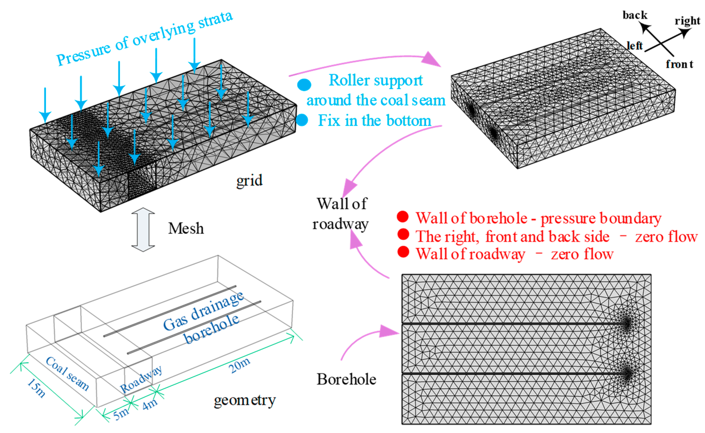
After gas extraction disrupts the gas pressure balance in the coal seam, the gas in the matrix diffuses into the fracture system, as the matrix system is equivalent to the internal mass source of the gas diffusion. According to the law of conservation of mass, we obtain the following for a unit volume of coal body:
t ( ϕ f ρ g ) = ( ρ g V ) + Q s ( 1 ϕ f )
where V is the gas seepage velocity in the crack (m/s). The gas seepage in the cracks conforms to Darcy’s law, and the seepage velocity is:
V = k e μ p f
By substituting Equations (22) and (23) into Equation (26), one obtains that, once the coal seam gas pressure balance is broken, the governing equation for the free gas pressure in the fracture with the dynamic change is as follows:
ϕ f p f t + p f ϕ f t = ( k e μ p f p f ) + 1 τ ( 1 ϕ f ) ( p m p f )

2.6. Model Settings

In this paper, finite element numerical simulation software is used, along with the built-in partial differential equation (PDE), to complete the modeling and solve the established fluid-structure coupling field. Figure 5 depicts a three-dimensional model of the roadway and borehole. As the borehole is under the pre-mining drainage stage, the mining pressures have little effect on the coal around the borehole, with a small fluctuation [31]. Thus, the effect of the overlying strata was equivalent to the constant pressure.
First, a tunnel excavation was carried out to truly restore the stress state of the coal seam, followed by the addition of gas drainage holes. The size of the mining roadway was 4.6 m × 2.8 m, and the average thickness of the coal seam was 3.91 m. The interval of two gas drainage boreholes was 5~15 m, and the length of the open-cut-off was 100~200 m. The model was aimed at the section with the two boreholes that were 15 m in width. To avoid mesh distortion and misconvergence, the model is five times smaller than its real world in length [32]. The length, width, and height are 20 m, 15 m, and 4 m, respectively. The pressure of the overlying strata σv was [33]:
σ v = 0.027 H
where H is burial depth.
As the mechanical parameter of the coal seam changes dramatically, to guarantee the representativeness of the parameters selected, the value was based on the previous research [19,34,35]. The relevant parameters used in the model are shown in Table 1.

3. Results and Discussion

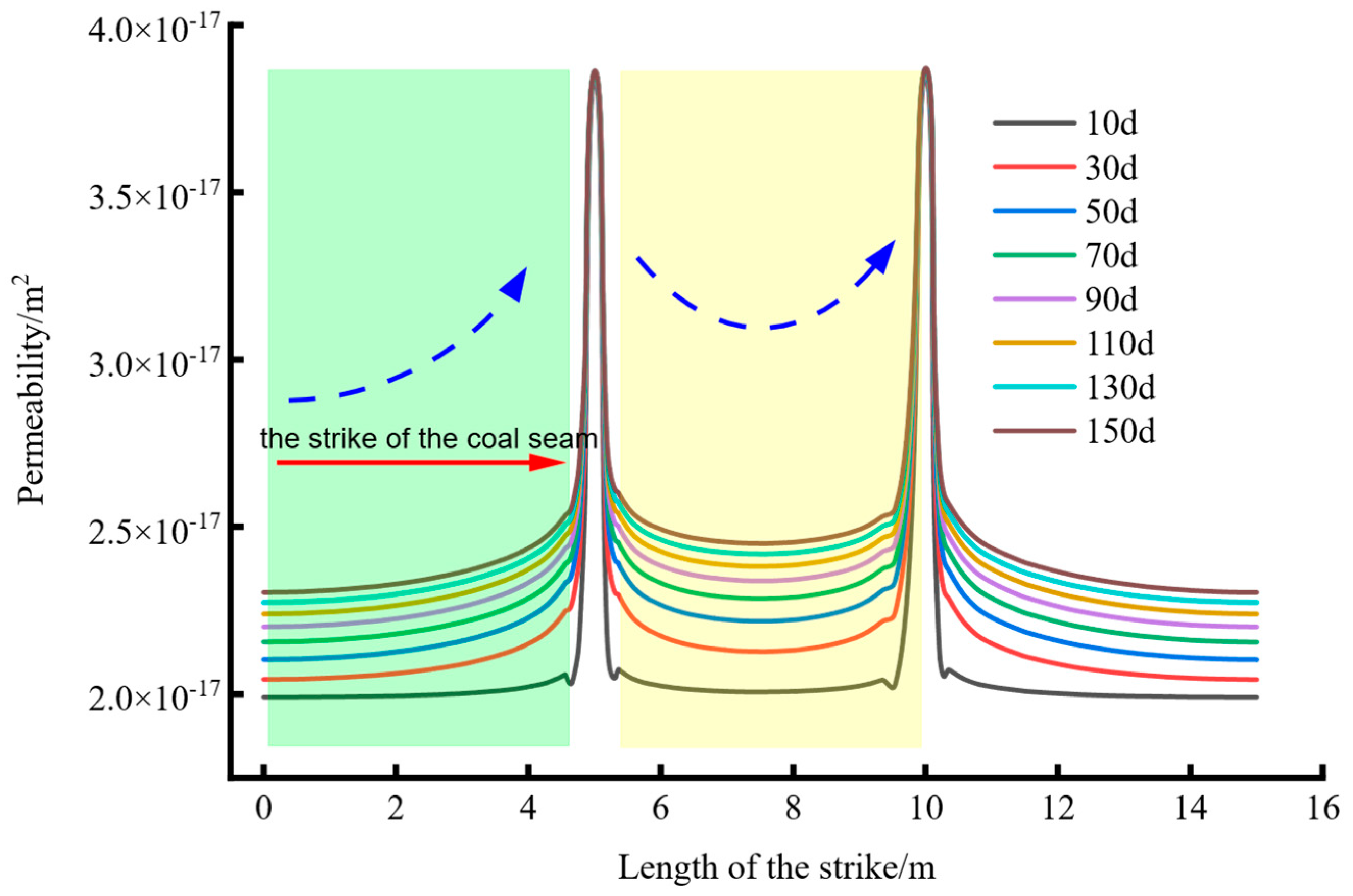
3.1. Characteristics of the Spatiotemporal Evolution of Coal Seam Permeability

According to the permeability evolution equation, the reason for the variation of the coal seam permeability is the change in the fracture gas pressure and matrix gas pressure coupling effect. Figure 6 depicts the evolution law of permeability along the strike of the coal seam. Around the borehole, the permeability of the coal seam increases while it decreases between the double holes and the distance from the borehole.
Figure 6 is divided into two sections for analysis: Area I and Area II. The permeability increases continuously along the strike in Zone I. This is because the negative pressure increases the closer you get to the borehole, and the rapid desorption of gas attracts the matrix shrinkage effect, which leads to the permeability of the coal seam continuously increasing. The distance between the two holes and the drainage holes decreases along Strike Zone II, and the permeability decreases first and then increases. This is because the gas pressure in the coal seam in the middle of the borehole is greater than the pressure in the coal seam around the hole. The greater the expansion stress, the greater the expansion deformation, resulting in a reduction in the permeability of the coal seam. The reason for the gradual increase is the same as in Region I.

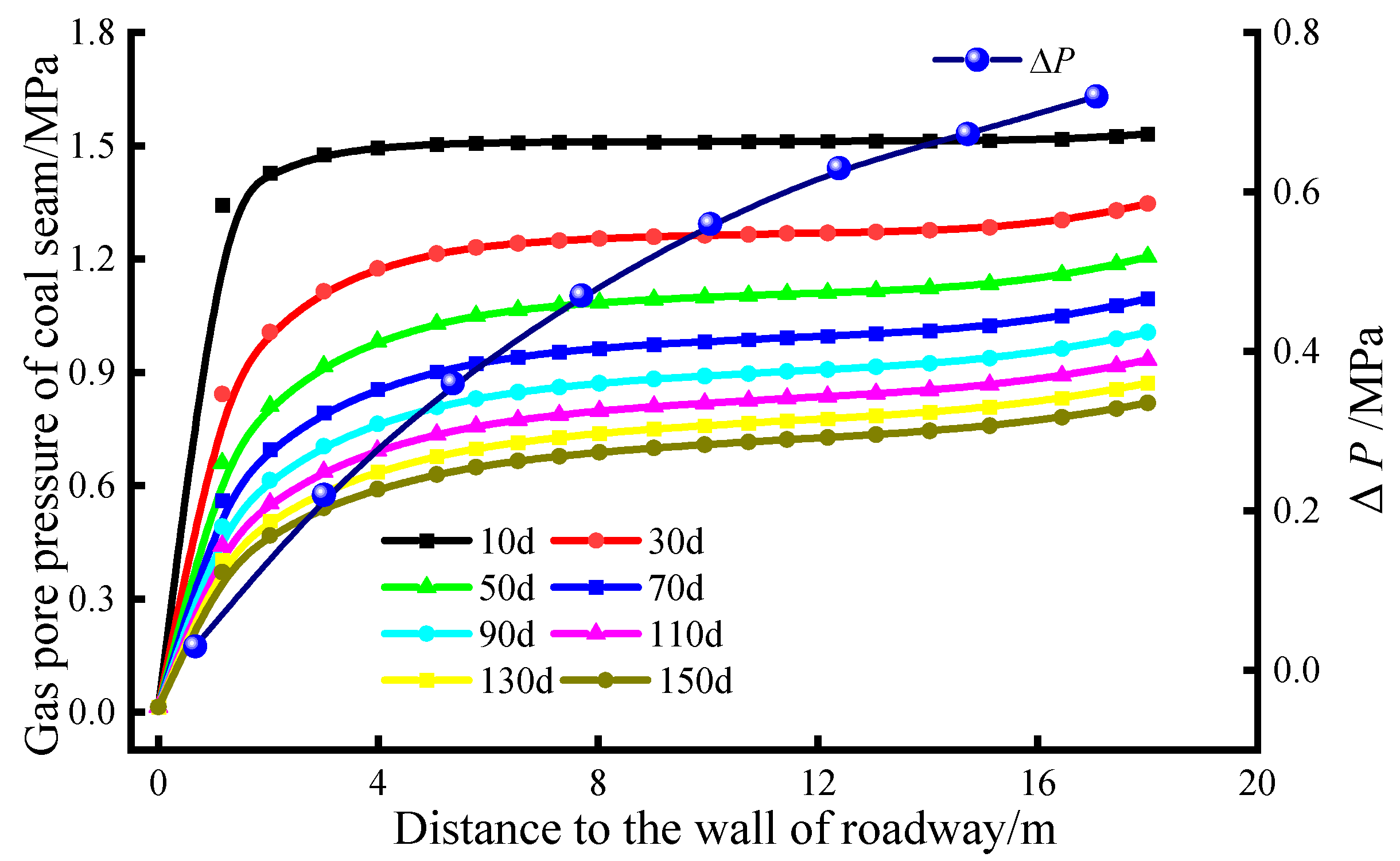
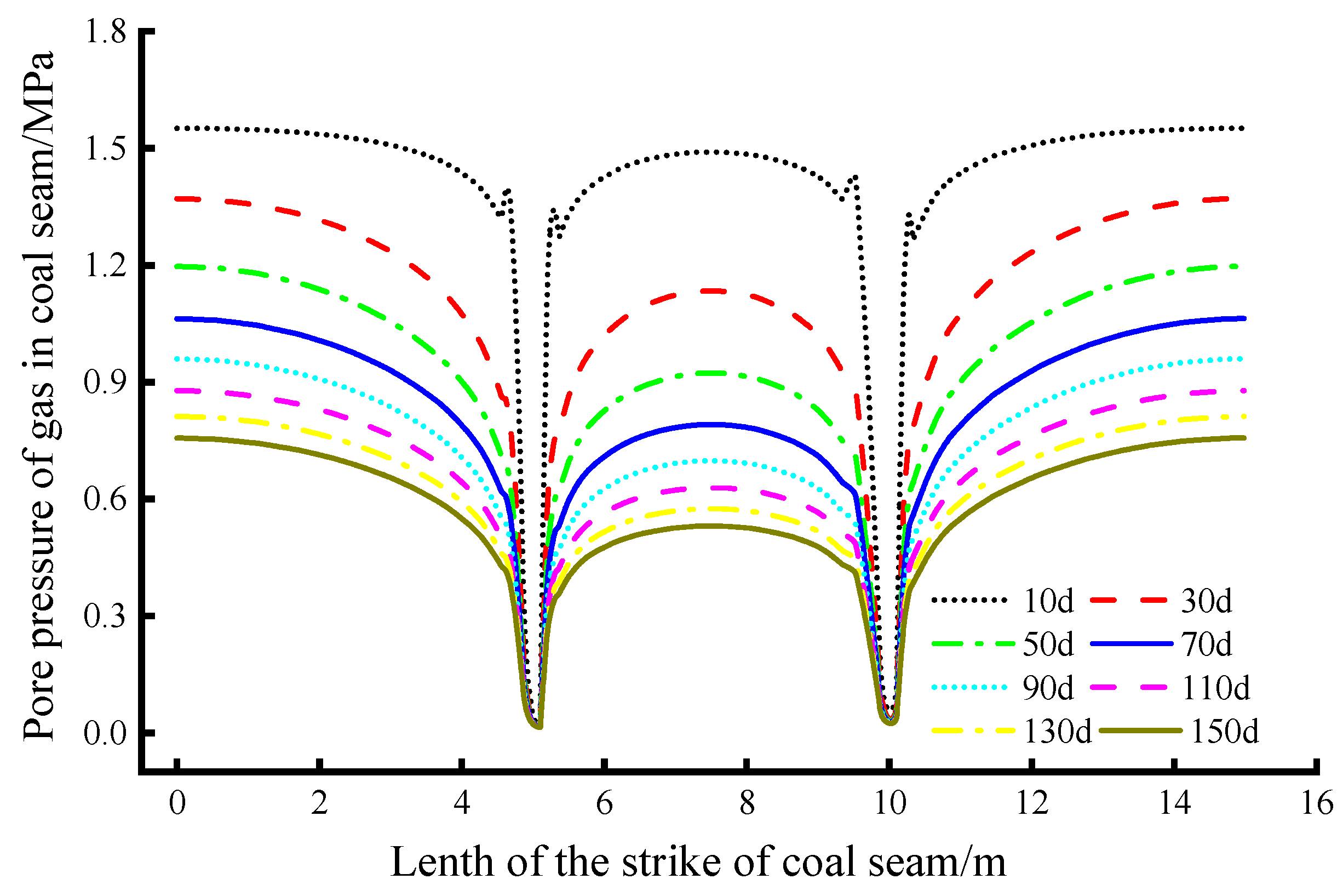
3.2. Time and Space Evolution of Coal Seam Gas Pressure

Most of the gas (the free state and adsorbed state) in the coal seam is stored in the pores of the coal seam [15], and there is little difference in the pressure of the matrix gas and fracture gas in the later stages of the drilling process [32], so focusing on gas pressure in the pores makes sense. Figure 7 illustrates the gas pressure distribution of the coal seam with the boreholes in the intersection model of the roadway and the boreholes for 90 days. The direction of the arrow in the figure represents the distribution pattern of the gas flow field. The roadway excavation resulted in extremely high permeability of the surrounding rock. In Area A (the broken area) of the figure, the closer it is to the drainage hole, the more obvious the decline in the gas concentration is.
The left side of Figure 7 shows the coal seam gas pressure section at various distances from the roadway, indicating that the area of the effective drainage area gradually decreases as the distance from the roadway increases. The first reason is the influence of the surrounding rock on the roadway; when the roadway is disturbed, the permeability and porosity of the surrounding rock increase, and the gas pressure of the coal seam decreases significantly; the second reason is the loss of negative drainage pressure. Careful observation revealed that the gas pressure distribution of the coal seam around the borehole at the cut plane 6 m from the surrounding rock of the roadway did not center on the borehole, implying a state of “eccentric circle.” The drainage area at the bottom of the borehole demonstrates the pressure distribution of coal seam gas with the borehole as the center. This situation is very likely to be affected by another drainage borehole. Additionally, it proves that as the hole gets closer to the roadway, the negative pressure increases, and the negative pressure at the bottom of the hole has little effect on the coal seam gas pressure due to the loss of negative drainage pressure.
In order to further clarify the flow law of gas pressure in the coal seam with the boreholes, Figure 8 depicts the time-dependent change in the coal seam gas pressure. The difference between the coal seam pore gas pressure and initial gas pressure was 0.03 MPa after 10 d, 0.16 MPa after 30 d, 0.6 MPa after 110 d, and 0.72 MPa after 150 d of extraction, respectively. The gas concentration decreased as the extraction time increased. The gas concentration decreased by 0.24 MPa in 30~50 d and 0.05 MPa in 130~150 d, indicating that the gas drainage concentration slowed gradually throughout the drilling process.
Figure 9 depicts the evolution process of the coal seam gas pressure along the strike. The closer you get to the borehole, the more noticeable the drop in the gas pressure is. On the one hand, during the initial stage of the extraction, which was less than 50 days [36], the drilling project caused cracks in the coal and rock mass surrounding the hole [5], and the new cracks connected with the existing cracks, forming an ideal gas flow path. On the other hand, the pressure difference between the borehole and the coal seam is relatively obvious, and the gas in the coal-rock matrix around the borehole rapidly desorbed, flowed into the fissures, and merged into the borehole.
As the extraction time increased, the pressure difference between the borehole and the coal-rock fractures around the borehole reduced, weakening the negative pressure. However, as the coal-rock matrix desorbed around the hole during the early stages of the extraction, the hole shrunk, and the permeability of the coal seam increased. Therefore, the reason for the decrease in gas concentration at this stage is the shrinkage effect of the matrix. On the other hand, the gas pressure between the boreholes was higher than the gas pressure around the boreholes. When combined with the mass source of Formula (2), it showed that the exchangeable gas volume between the holes was greater than the gas volume around the holes. As illustrated in Figure 3, the coal body stress was highly concentrated in this area, and when combined with Formula (1), the expansion deformation increased, the porosity decreased, and a certain bottleneck effect formed between the boreholes.
According to Figure 9, the pressure difference between the left and right side and the middle reflects the improvement of gas drainage relative to the one borehole, which is listed in Table 2. The max difference reached 0.2740 MPa at 50 d, with a 17.56% improvement. Since the max value, the difference was gradually decreased until, at 150 d, the ratio of improvement was about 14.48%.

3.3. Field Test and Analysis

The purpose of this paper is to establish a coal seam gas seepage model with a three-dimensional roadway and borehole crossing structure based on the actual situation of the drilling arrangement along the bed of the 814 air inlet roadway in the Huangling No. 1 Coal Mine and in the parameters of the study [15], as well as the double porous medium. The construction scenario of first excavating the roadway and then drilling makes the model more realistic.
In order to further illustrate the consistency between the model and the field, the method based on the residual gas content was tested to determine the effective extraction radius in the No.8 borehole of the 814 air inlet in the well. It should be noted here that the measurement procedure is designed to measure the residual gas content of multiple groups.
Figure 10 shows the matching results of the effective drainage radius of the borehole by a numerical calculation and the field test. As illustrated in the figure, the field test and numerical simulation both follow the same law, with the effective radius increasing as the drainage time increases. After a certain period of time, the effective radius becomes relatively stable, implying that the coal seam gas seepage model with a three-dimensional roadway and borehole crossing structure can more accurately recreate the actual extraction process.

4. Conclusions

This paper proposes a three-dimensional intersection model of a deep soft rock roadway and a gas drainage borehole to explore the spatial evolution characteristics of the gas pressure and permeability of the coal seam around the boreholes. With the assumption of dual porous media, the near-real stress distribution, and the concentration factors of the surrounding rock after the roadway excavation, a multi-field coupled seepage model between tunnel and borehole has been established. Through the calculation and field test, we found that:
(1) The roadway excavation causes localized stress in some areas of the surrounding rock, reducing the strength of the coal body, increasing the expansion stress, and increasing the gas adsorption capacity of the coal body.
(2) As the distance between the drainage boreholes decreases along the strike of the coal seam, the permeability decreases first and then increases in the condition of the deep soft rock roadway. The gas pressure in the coal seam area in the center of the borehole is greater than the pressure in the coal seam around the boreholes; the greater the expansion stress and deformation, the lower the permeability of the coal seam. When approaching the next borehole, the greater the negative pressure, the faster the gas desorbs, attracting the matrix shrinkage effect and leading to an increasing coal seam permeability rate.
(3) The improvement of gas drainage with the overlapping arrangement of the two boreholes firstly increases and then decreases as time goes on. On the 50 d, the ratio of improvement reached a maximum of 17.56%.
(4) When the field test results and numerical simulation of the effective area of gas extraction are compared, the effectiveness of the model is verified. Taking the change of the porosity and the permeability into the model, it is able to calculate the radius of gas drainage more accurately.

Author Contributions

Conceptualization, L.Z. and C.J.; methodology, C.J.; software, L.Z.; validation, L.Z. and R.B.; investigation, R.B.; writing—original draft preparation, C.J.; writing—review and editing, L.Z. and T.Z.; visualization, C.J.; project administration, S.L. and T.Z.; funding acquisition, L.Z and R.B. All authors have read and agreed to the published version of the manuscript.

Funding

This work was supported by the National Natural Science Foundation of China [grant numbers 52104216, 52104225] and the China Postdoctoral Science Foundation [grant numbers 2020M683680XB].

Institutional Review Board Statement

Not applicable.

Data Availability Statement

Not applicable.

Acknowledgments

Thanks for the help of Jinyu Wu in translating.

Conflicts of Interest

The authors declare no conflict of interest.

References

  1. Yuan, L. Theory and practice of integrated coal production and gas extraction. Int. J. Coal Sci. Technol. 2015, 2, 3–11. [Google Scholar] [CrossRef]
  2. Pang, M.; Zhang, T.; Meng, Y.; Ling, Z. Experimental study on the permeability of crushed coal medium based on the ergun equation. Sci. Rep. 2021, 11, 23030. [Google Scholar] [CrossRef] [PubMed]
  3. Xia, T.; Zhou, F.; Liu, J.; Hu, S.; Liu, Y. A fully coupled coal deformation and compositional flow model for the control of the pre-mining coal seam gas extraction. Int. J. Rock Mech. Min. Sci. 2014, 72, 138–148. [Google Scholar] [CrossRef]
  4. Frank, H.; Ting, R.; Naj, A. Evolution and application of in-seam drilling for gas drainage. Int. J. Min. Sci. Technol. 2013, 23, 543–553. [Google Scholar] [CrossRef]
  5. Zhang, T.; Jing, C.; Zhang, L.; Ji, X.; Pan, H. Strain localization characteristics of perforation failure of perforated specimens. Meitan Xuebao/J. China Coal Soc. 2020, 45, 4087–4094. [Google Scholar]
  6. Zhang, T.; Zhang, L.; Li, S.; Liu, J.; Pan, H.; Song, S. Stress inversion of coal with a gas drilling borehole and the law of crack propagation. Energies 2017, 10, 1743. [Google Scholar] [CrossRef] [Green Version]
  7. Hu, G.Z.; Wang, H.T.; Tan, H.X.; Fan, X.G.; Yuan, Z.G. Gas seepage equation of deep mined coal seams and its application. J. China Univ. Min. Technol. 2008, 18, 483–487. [Google Scholar] [CrossRef]
  8. Lin, B.; Song, H.; Zhao, Y.; Liu, T.; Kong, J.; Huang, Z. Significance of gas flow in anisotropic coal seams to underground gas drainage. J. Pet. Sci. Eng. 2019, 180, 808–819. [Google Scholar] [CrossRef]
  9. Junxiang, Z.; Bo, L.; Yuning, S. Dynamic leakage mechanism of gas drainage borehole and engineering application. Int. J. Min. Sci. Technol. 2018, 28, 505–512. [Google Scholar] [CrossRef]
  10. Connell, L.D. Coupled flow and geomechanical processes during gas production from coal seams. Int. J. Coal Geol. 2009, 79, 18–28. [Google Scholar] [CrossRef]
  11. Connell, L.D.; Sander, R.; Camilleri, M.; Heryanto, D.; Pan, Z.; Lupton, N. Nitrogen enhanced drainage of co 2 rich coal seams for mining. Int. J. Min. Sci. Technol. 2017, 27, 755–761. [Google Scholar] [CrossRef]
  12. Celik, E.; Hoang, L. Maximum estimates for generalized forchheimer flows in heterogeneous porous media. J. Differ. Equ. 2017, 262, 2158–2195. [Google Scholar] [CrossRef] [Green Version]
  13. Bukowski, P. Water hazard assessment in active shafts in upper silesian coal basin mines. Mine Water Environ. 2011, 30, 302–311. [Google Scholar] [CrossRef] [Green Version]
  14. Davarpanah, A.; Mirshekari, B. Experimental investigation and mathematical modeling of gas diffusivity by carbon dioxide and methane kinetic adsorption. Ind. Eng. Chem. Res. 2019, 58, 12392–12400. [Google Scholar] [CrossRef]
  15. Liu, Q.; Cheng, Y.; Wang, H.; Zhou, H.; Liang, W.; Wei, L.; Liu, H. Numerical assessment of the effect of equilibration time on coal permeability evolution characteristics. Fuel 2015, 140, 81–89. [Google Scholar] [CrossRef]
  16. Wei, X.; Wang, G.G.X.; Massarotto, P.; Golding, S.D.; Rudolph, V. A review on recent advances in the numerical simulation for coalbed-methane-recovery process. SPE Reserv. Eval. Eng. 2007, 10, 657–666. [Google Scholar] [CrossRef] [Green Version]
  17. Liu, J.; Chen, Z.; Elsworth, D.; Miao, X.; Mao, X. Evaluation of stress-controlled coal swelling processes. Int. J. Coal Geol. 2010, 83, 446–455. [Google Scholar] [CrossRef]
  18. Seomoon, H.; Lee, M.; Sung, W. Analysis of sorption-induced permeability reduction considering gas diffusion phenomenon in coal seam reservoir. Transport. Porous Media 2015, 108, 713–729. [Google Scholar] [CrossRef]
  19. Zhu, W.C.; Liu, J.; Sheng, J.C.; Elsworth, D. Analysis of coupled gas flow and deformation process with desorption and klinkenberg effects in coal seams. Int. J. Rock Mech. Min. Sci. 2007, 44, 971–980. [Google Scholar] [CrossRef]
  20. Wang, S.; Elsworth, D.; Liu, J. Permeability evolution during progressive deformation of intact coal and implications for instability in underground coal seams. Int. J. Rock Mech. Min. Sci. 2013, 58, 34–45. [Google Scholar] [CrossRef]
  21. Xue, Y.; Gao, F.; Gao, Y.; Cheng, H.; Liu, Y.; Hou, P.; Teng, T. Quantitative evaluation of stress-relief and permeability-increasing effects of overlying coal seams for coal mine methane drainage in wulan coal mine. J. Nat. Gas Sci. Eng. 2016, 32, 122–137. [Google Scholar] [CrossRef]
  22. Cheng, Y.; Huo, A.; Zhang, J.; Lu, Y. Early warning of meteorological geohazard in the loess plateau: A study in huangling county of shaanxi province in china. Environ. Earth Sci. 2015, 73, 1057–1065. [Google Scholar] [CrossRef]
  23. Tang, W.; Zhai, C.; Yu, X.; Xu, J.; Sun, Y.; Cong, Y.; Zheng, Y.; Li, Y. Numerical study on the effect of sudden change in coal property on coal and gas outburst during roadway excavation. Environ. Earth Sci. 2022, 81, 328. [Google Scholar] [CrossRef]
  24. Durucan, S.; Edwards, J.S. Effects of stress and fracturing on permeability of coal. Min. Sci. Technol. 1986, 3, 205–216. [Google Scholar] [CrossRef]
  25. Ma, Y.-K.; Nie, B.-S.; He, X.-Q.; Li, X.-C.; Meng, J.-Q.; Song, D.-Z. Mechanism investigation on coal and gas outburst: An overview. Int. J. Miner. Metall. Mater. 2020, 27, 872–887. [Google Scholar] [CrossRef]
  26. Guo, P.; Cao, S.-G.; Zhang, Z.-G.; Luo, F.; Liu, Y. Theoretical study of deformation model of coal swelling induced by gas adsorption. Yantu Lixue/Rock Soil Mech. 2014, 35, 3467–3472. [Google Scholar]
  27. Palmer, I.; Mansoori, J. How permeability depends on stress and pore pressure in coalbeds: A new model. SPE Reserv. Eng. 1998, 1, 539–543. [Google Scholar] [CrossRef]
  28. Zhao, Y.; Hu, Y.; Zhao, B.; Yang, D. Nonlinear coupled mathematical model for solid deformation and gas seepage in fractured media. Transp. Porous Media 2004, 55, 119–136. [Google Scholar] [CrossRef]
  29. Wu, Y.-S.; Pruess, K.; Persoff, P. Gas flow in porous media with klinkenberg effects. Transp. Porous Media 1998, 32, 117–137. [Google Scholar] [CrossRef]
  30. Mora, C.A.; Wattenbarger, R.A. Analyst and Verification of Dual Porosity and CBM Shape Factors. In Proceedings of the Canadian International Petroleum Conference, CIPC 2006, Calgary, AB, Canada, 13–15 June 2006. [Google Scholar]
  31. Haifeng, W.; Yuanping, C.; Lei, W. Regional gas drainage techniques in Chinese coal mines. Int. J. Min. Sci. Technol. 2012, 22, 873–878. [Google Scholar] [CrossRef]
  32. Zhang, T.-J.; Pang, M.-K.; Jiang, X.-K.; Peng, W.-Q.; Ji, X. Influence of negative pressure on gas percolation characteristics of coal body in perforated drilling hole. Yantu Lixue/Rock Soil Mech. 2019, 40, 2517–2524. [Google Scholar]
  33. Brown, E.T.; Hoek, E. Trends in relationships between measured in-situ stresses and depth. Int. J. Rock Mech. Min. Sci. Geomech. Abstr. 1978, 15, 211–215. [Google Scholar] [CrossRef]
  34. Xia, T.; Zhou, F.; Liu, J.; Gao, F. Evaluation of the pre-drained coal seam gas quality. Fuel 2014, 130, 296–305. [Google Scholar] [CrossRef]
  35. Liu, Q.; Cheng, Y.; Li, W.; Jin, K.; He, T.; Zhao, W. Mathematical model of coupled gas flow and coal deformation process in low-permeability and first mined coal seam. Yanshilixue Yu Gongcheng Xuebao/Chin. J. Rock Mech. Eng. 2015, 34, 2749–2758. [Google Scholar]
  36. Liu, T.; Lin, B. Time-dependent dynamic diffusion processes in coal: Model development and analysis. Int. J. Heat Mass Transf. 2019, 134, 1–9. [Google Scholar] [CrossRef]
Figure 1. Mechanical model of the borehole and roadway intersection. (2# represents the second layer of coal which is a sample differentiation symbol to indicate different coal seams.)
Energies 15 05012 g001
Figure 2. Three-dimensional spatial structure of gas drainage borehole and roadway crossing.
Energies 15 05012 g002
Figure 3. Schematic diagram of effective stress and coal body strength of coal containing gas.
Energies 15 05012 g003
Figure 4. Coal seam gas migration process.
Energies 15 05012 g004
Figure 5. The establishment of the tunnel and borehole cross model.
Energies 15 05012 g005
Figure 6. Permeability evolution characteristics of the coal seam along the strike.
Energies 15 05012 g006
Figure 7. The pore gas cloud map of the 90 d coal seam was extracted.
Energies 15 05012 g007
Figure 8. Evolution process of the coal seam gas pressure with time.
Energies 15 05012 g008
Figure 9. Coal seam gas pressure evolution process along the strike.
Energies 15 05012 g009
Figure 10. Comparison of the effective extraction radius between a numerical calculation and field test.
Energies 15 05012 g010
Table 1. Model-related parameter.
ParameterValueParameterValue
Initial permeability of coal/mD0.02Coal seam initial temperature/K293.14
Initial porosity of coal matrix0.06Limiting Adsorption Swell Variable A0.004
Initial gas pressure of coal fractures/MPa1.56Limiting Adsorption Swell Variable B0.008
Initial gas pressure of coal matrix/MPa1.56Elastic modulus of coal/MPa2713
Initial coal gas diffusion coefficient/m2·s−13.48 × 10−11Coal Matrix Elastic Modulus/MPa8139
Coal apparent density/kg·m31300Klinkenberg coefficient/kPa10
Gas dynamic viscosity/Pa·s1.84 × 10−5The amount of gas adsorbed per unit mass of coal, a/m3·kg−10.015
Coal Poisson’s ratio0.35Adsorption constant of coalb/MPa−16.11
Table 2. Improvement of gas drainage.
Time of gas drainage (day)1030507090110130150
Max difference of pressure (MPa)0.06120.23070.27400.26180.26150.24930.23710.2258
The ratio of improvement (%)3.94%15.19%17.56%16.78%16.76%15.98%15.20%14.48%
Publisher’s Note: MDPI stays neutral with regard to jurisdictional claims in published maps and institutional affiliations.

