Article

Analysis of Impact of a Novel Combined Casing Treatment on Flow Characteristics and Performance of a Transonic Compressor

School of Chemical Engineering and Technology, Xi’an Jiaotong University, Xi’an 710049, China
*
Author to whom correspondence should be addressed.
Energies 2022, 15(14), 5066; https://doi.org/10.3390/en15145066
Submission received: 15 May 2022 / Revised: 13 June 2022 / Accepted: 21 June 2022 / Published: 11 July 2022

Abstract

:
To reduce the negative impacts of stall and surge on compressor performance, a novel combined casing treatment (CCT) structure with axial skewed slots and injection groove is proposed in this paper. The aerodynamic performance, as well as the mechanisms of loss generation, of a transonic axial compressor with NASA Rotor 67 are investigated numerically. The simulation results indicate that, compared with individual casing treatment method, the CCT works effectively with regard to operation performance. The stall margin (SM) is increased by 14.7% with 1.12% decrease in the peak efficiency. The interaction of axial skewed slots and injection groove can be explained by the enhancement of exchange flow in slots and axial motion of fluid. As a result, the leakage flow near the blade tip is eliminated and the flow separation is further suppressed. What is more, an analysis of entropy generation is also conducted. The results reveal that the effect of CCT on loss reduction mainly concentrates in the tip part of the blade, with the loss decrease about 14.46% compared with the original rotor. The best control effect can be expected by appropriate match between geometrical parameters of axial skewed slots and mass flow rate of injection from the parameter analysis.

1. Introduction

With the development of aerospace, energy and chemical industries, higher requirements for compressors are proposed as the increasing of stage loading. However, the insufficient stability resulting in rotating stall and surge limited its further application [1]. Casing treatments (CTs), as one of the most effective techniques used for extending stall margin (SM) and improving operation stability, have gained a lot of interest in recent years. Generally speaking, the casing treatments method can be broadly classified into two categories: active and passive [2]. The former includes vortex generator jets [3], synthetic jet [4] and boundary layer suction [5], while the latter includes blade bending and sweeping [6], end-wall slotting [7] and geometric deformation of the passage [8].
The active methods are able to provide stability improvement in varied operating conditions. The passive methods, on the contrary, are always accompanied with reduced efficiency despite their compactness and simpleness. For active methods, steady injection can be adopted to suppress or even eliminate the flow separation by adding energy into the low-velocity fluid near the boundary layer. Benhegouga et al. [9] introduced a generator located at the top of the blade leading edge for injection. As a result, the total pressure ratio and the SM were increased by about 0.5% and 6.4%, respectively, which contributed to the decrease in unstable low-velocity fluid at the blade tip. Mao et al. [10] simulated the flow field of compressor cascade with different injection angles and mass flow rates. The results indicated that the end-wall injection attenuated the separation in the corner and reduced the flow loss effectively. However, the inverse pressure gradient in the middle span of the blade increased. Li et al. [11] investigated the effect of tip injection on a three-stage axial compressor. They found that the stall resulted from the unsteady tip leakage flow caused by tip radial distortion. In addition, the injection device negatively impacted the compressor performance with the increase in injected momentum ratios. The effect of an injection device with different numbers and mass flow rates on a centrifugal compressor was studied experimentally by Yang et al. [12]. They found that the stability enhancement was explained by the reduction in flow angle. In addition, the optimal performance of compressor was achieved when the injection rate was set as 4.5% of design mass flow with four holes. In addition, the effect could be further improved with lower rotating speed.
As a popular passive flow control method, end-wall slotting is simple and widely utilized for recovering SM during the starting phase of a compressor. The basic idea for employing slots is to attenuate the tip leakage vortex. Wilke et al. [13] studied the effect of axial slots on the transonic compressor efficiency, as well as the inherent mechanism of SM improvement. The result revealed that the extension of stable operating range owed to the occurrence of counterclockwise vortex in the slots. Florian et al. [14] found that the intensity of the shock was reduced due to the reinjected flow in the slots. However, the load of the blade near the hub was increased, where the corner separation became critical for aerodynamic stability. Zhang et al. [15] investigated the influence of the position of axial skewed slots, and the best stabilization effect was obtained when the center of the slots and the rotor blade row coincided in axial position. On the other hand, the stability enhancement effect weakened as the vortex in the slot, the so-called exchange flow, was attenuated. The feasibility of slotting was also verified by Cravero et al. [16] in a centrifugal compressor. The results showed that the operating range could be extended significantly by 11% at the expense of operation efficiency. The mechanism could be explained by the recirculation of the low momentum fluid. He et al. [17] applied a self-recirculation CT device in a high-pressure ratio centrifugal compressor. The results indicated that the surge was constrained by proposed CT devices through eliminating the vortex structures. In addition, considering the drawback of reducing the choke mass flow, the active methods were recommended for further development.
Actually, some efforts have been made to attain satisfactory overall performance by combining two kinds of methods together considering their complementary features. Zhang et al. [18] added tangent injection generators to the circumferential grooves. The simulation result indicated that the original ability of circumferential groove to suck or blow the boundary layer in the tip area was enhanced as the radial-induced velocity increased by tangent injection. Kim et al. [19] combined the injection structure with casing groove. A better performance of the SM and peak efficiency increase by 6.08% and 0.6%, respectively, was obtained. The results also indicated that the stall was delayed due to the suppressed region of low speed. However, no significant improvement at the blade root was observed. Furthermore, a hybrid multi-objective evolutionary algorithm was adopted by Kim et al. [20] to optimize the proposed CT structure. Three parameters, including length and height of the grooves and the injection mass flow rate, were chosen as variables. The peak adiabatic efficiency was found to decrease as a high SM was obtained, and vice versa. A final optimal design is obtained with the stall margin and peak adiabatic efficiency increased by 8.59% and 0.96%, respectively. A new combined CT consisting of grooves, tip injection and ejection was proposed by Dinh et al. [21]. The loss of the total pressure ratio was further decreased compared with the case-equipped casing groove and injection only. In addition, the geometry of grooves rather than mass flow rate was recommended to be optimized through parameter analysis.
On the other hand, the utilization of CT may bring significant efficiency penalty [22], outbalancing the benefit of SM extension. In order to design an efficiency-friendly CT structure, many efforts have been made in revealing the loss mechanism. Koch et al. [23] evaluated four types of losses, including profile loss, end-wall loss, shockwave loss and part-span shroud loss in low-speed axial compressors. However. significant error exists in the analysis of loss sources and magnitudes because of the simplifying assumptions. Sun et al. [24] quantified the flow loss based on the second law of thermodynamics and identified the main loss region in a transonic compressor. The results indicated that the largest losses came from the boundary layers due to the interaction between the main flow and the shock wave, followed by the tip leakages, wakes and core flow. Xi et al. [25] studied the spatial distribution of entropy generation and quantitated the local losses. The result showed the efficiency was gradually increasing as the tip gap vanished, and leakage flow and shock wave were two dominant contributors to the total loss.
In short, although the combination of CTs is expected to achieve a better performance, the current combined CT structures mostly integrate slots and injection at the blade tip. On the other hand, there is a lack of literature associated with the flow separation in the lower half of the blade, which is also of great importance for compressor stability [14,26]. What is more, challenges arise for analyzing the loss mechanisms of the more complicated flow process when adopting combined CT. Motivated by the above, a novel combined CT structure is proposed on the basis of axial skewed slots at the blade tip and a circumferential injection groove at the blade root. By means of numerical simulation, the combined CT proved effective for stability enhancement with little efficiency penalty. The details of the flow field were also investigated to explore the flow control mechanism of the combined structure. Furthermore, the flow loss was quantified for loss mechanism analysis, and key parameters for the combined CT were also examined about the effects on the local loss generation.

2. Model Description

The compressor rotor studied in this paper is NASA rotor 67 due to its typical stall phenomena when operated close to surge. The number of blades is 22, the design speed is 16043 r/min, and the design pressure ratio is 1.63. Detailed geometric data can be obtained from the report by Strazisar et al. [27], and the schematic diagram is shown in Figure 1.
The axial skewed slots are adopted in this study according to the results of Liu et al. [28], and the main parameters are listed in Table 1. In addition, the injection groove is introduced to the lower end-wall to inhibit the flow separation in the corner area. The groove is placed at 90% of the chord length with 1mm width. In addition, the geometry of combined CT is shown in Figure 2.
The computational domain is shown in Figure 3 and a single blade passage mode with inlet and outlet axial co-ordinates is adopted since Du et al. [29] have verified that the characteristics for all the blade passages are identical while the self-induced unsteadiness is captured in the transonic compressor. A structured grid system is constructed using the software Turbo Grid in ANSYS Workbench 17.0, in which the mesh of blades is covered by the O-blocks near the blade surfaces and H/J/C/L-blocks in other regions. The near-wall grid is adjusted to keep the dimensionless parameter, y+, below 3. The total number of grids inside the passage, inlet and outlet is 1.5 × 10⁶, 1.3 × 10⁵ and 4.5 × 10⁵, respectively. What is more, the structured and unstructured grids of the axial skewed slots and injection groove are created by the individual block meshing tool ICEM, resolved with 2 × 10⁴ and 1.5 × 10⁴ grids.
The shear stress transport (SST) k-ω model is used for turbulence, and the energy equation is solved at the same time, considering the Mach numbers (Ma) are greater than 1 during operation. The simulation is carried out in the CFX solver for steady state, since steady flow distribution is also crucial for evaluating the effect of a CT structure [30]. The physical time step is 5 × 10⁻⁴ s with the residual target of 1 × 10⁻⁶. The working fluid is considered as ideal gas herein, and the total pressure and temperature at inlet are set to 101,325 Pa and 288.15 K. The mass flow rate of the outlet is set as designed valve, i.e., 33.25 kg/s. The “frozen rotor” is used for the rotor-to-stator interface. Nonslip and adiabatic conditions were imposed on all solid walls. What is more, the numerical model for the single rotor and the grid independence of the computations were validated previously [31]; as shown in Figure 4, the last stable point is obtained through increasing back pressure until the calculation cannot converge. The results agree well with the experimental data with a relative error within 3%, proving the ability for the following analysis.
It is worth noting that, since part of the fluid is injected into the passage by groove, the effect of the excess fluid on the overall performance of the compressor should be considered. Following the derivation procedure by Wang et al. [32], the modified formula considering the injection is obtained as:
η i n = W a W = ( P o u t P i n ) γ 1 γ 1 ( T o u t T i n ) ( m i m o u t ) ( T i T i n + m i n / m i )
where W a is the required isentropic compression work, W is the actual work done, P o u t is the outlet pressure, P i n is the inlet pressure, γ is the specific heat ratio, T i n is the inlet temperature, T o u t is the outlet temperature, T i is the temperature of the injection, m i n is the mass flow rate of inlet, m o u t is the mass flow rate of outlet and m i is the mass flow rate of injection.

3. Results

3.1. Effect of Combined CT on Transonic Compressor

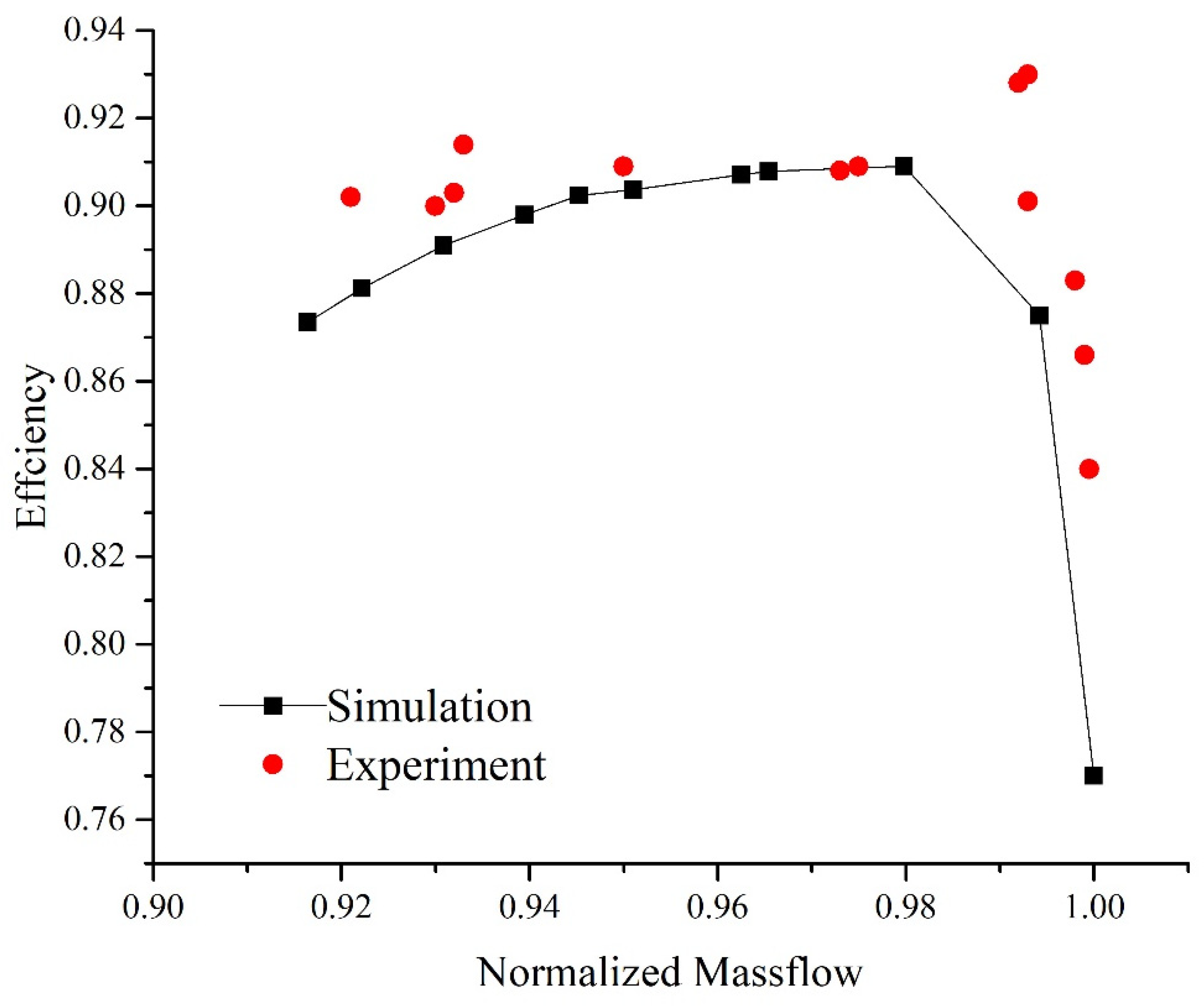
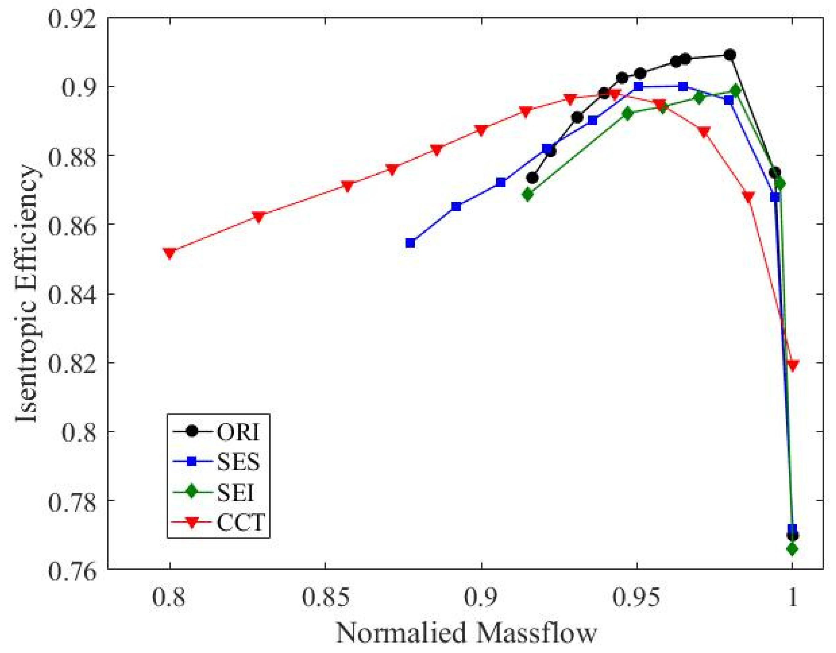
3.1.1. Overall Performance

The ability of the stability improvement of CTs can be evaluated using SM, and it is defined as follows:
S M = ( π N S * m N P E * π N P E * m N S * 1 ) × 100 %
where π N S * and m N S * represent the pressure ratio and mass flow rate near the stall point; π N P E * and m N P E * represent the pressure ratio and flow rate near the peak efficiency point.
The performance curves of the original NASA 67 rotor (ORI), the rotor with single end-wall slots (SES) or single end-wall injection (SEI), and the rotor with newly proposed combined CT (CCT) are shown in Figure 5. The simulations were carried out at the design rotational speed of ORI scheme and the mass flow rate has been normalized. It is obvious that the axial skewed slots enlarge the stable operating range of rotor significantly in SES with the peak efficiency lower than that in ORI by 0.91%. The curve of SEI is almost the same as ORI in regard of stable operating range. However, the efficiency penalty even increases to 1.06%. Most notably, the CCT scheme displays a broad stable operating range, with the peak efficiency decreasing by about 1.12%. The results of SM also illustrate this point that the SM of ORI, SES, SEI and CCT schemes are 10.8%, 16.2%, 10.9% and 25.5%, respectively. In general, the stable operating range of the compressor is expected to be extended with SES at the cost of decreasing the compressor efficiency [33], and the effect of injection is far from satisfactory in terms of the performance curve. The CCT scheme shows the best comprehensive performance considering both stability and efficiency.

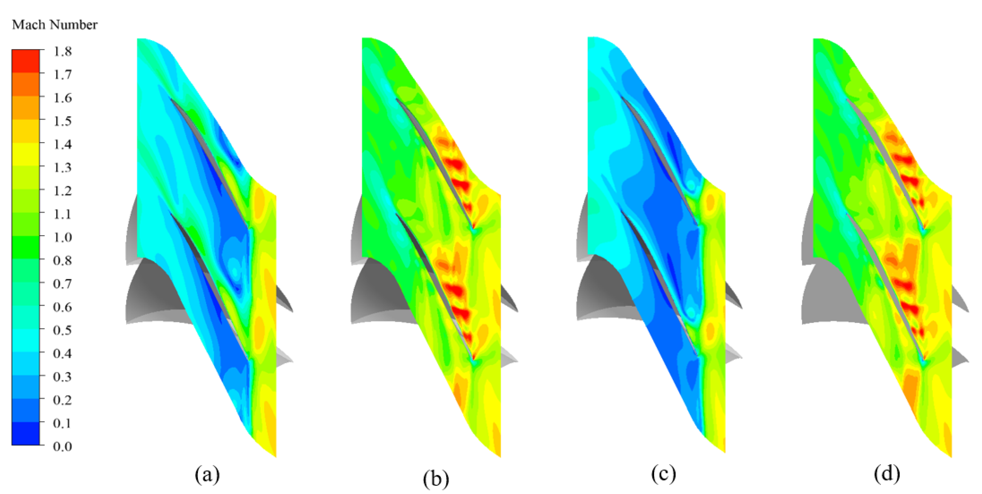
3.1.2. Flow Field Characterization

Since the mechanism of stall in NASA rotor 67 can be explained by the unsteadiness of tip leakage flow [29], to explain the distinctions in performance curves, it is necessary to study the flow characteristics at the blade in different schemes. The streamlines at the blade tip and the Ma contours at 98% span under near-stall condition of ORI scheme are shown in Figure 6 and Figure 7. Two types of vortices can be observed near the blade tip in Figure 6a, i.e., leakage vortex and separation vortex. The leakage flow at the leading edge crosses the tip, rolls up to form the leakage vortex, and the center portion of the vortex trajectory becomes perpendicular to the axial direction. On the other hand, the low-velocity fluid on the suction surface accumulates at the trailing edge of the tip, where separation vortex forms under the shear action of the wall boundary layer and detaches from the suction side. Since the leakage flow is formed, as Figure 7a shows, the mixing loss increases. Meanwhile, the outlet flow in the tip channel decreases, which tends to cause the blockage and enhance the instability.
In Figure 6b, the leakage vortex is significantly restrained, manifested in the disappearance of the circumferential flow at the leading edge. The overall velocity of the passage is increased from Figure 7b, and no low-velocity region appears, reducing the intensity of interaction between leakage vortex and shock wave. The leakage vortex is hard to break [34], further illustrating that the stall inception can be delayed by improving the flow in the rotor tip region.
In Figure 6c, obvious circumferential flow is observed at the leading edge and the intensity of the leakage vortex increases significantly. That is to say, single injection will aggravate the instability at the blade tip. As seen in Figure 7c, the low-velocity region almost covers the whole flow passage due to the enhanced leakage flow; hence, the blockage becomes worse with larger efficiency loss.
In Figure 6d, the flow field shown is almost identical with SES, indicating that the combination still retains the fundamental mechanism of axial skew slots. However, since the injection increases the momentum along the radial direction, the growth of the separation vortex at the trailing edge is restrained. In addition, in Figure 7d, the overall velocity in the passage increases and the separation subjected to the sudden pressure rise can be suppressed accordingly [35]. Therefore, compared with axial skewed slots, the combination of CTs can further improve the stability by weakening the effect of the separation vortex.
In order to verify the influences of low-energy flows, Figure 8 shows the contour of relative total pressure coefficient, which is defined as:
C r e f = 2 ( P r t P r e f ) ρ U t i p 2
where P r t is relative total pressure, P r e f is reference pressure, ρ is the density of the fluid and U t i p is the speed of the blade tip.
The region influenced by the tip leakage flow can be identified by low C r e f area, since no shaft work is taken. The contours of C r e f are given to clearly distinguish the interface of tip leakage flow and main flow. In Figure 8a, it can be observed that there emerges a local low C r e f region, indicating that the fluid is dominated by the leakage flow at the leading edge and then moving downstream after the interface. Since this interface is likely to stretch all the way across the blade passage, the compressor is close to stall. In Figure 8b, the passage is nearly occupied by low C r e f region. The incoming main flow can barely go through the blade passage and the blockage occurs accordingly. It can be explained that the fluid is expected to accumulate at the blade tip due to the excess fluid from the groove. Then, the blockage in the circumferential direction occurs and hinders the improvement of SM. In Figure 8c,d, the interface of tip leakage flow and main flow almost disappears, indicating the fluid is dominated by the main flow without blockage. What is more, the area of high C r e f region in CCT scheme penetrates further down along the downstream, which is attributed to the further restraint of leakage flow. Hence, it is not surprising that the stability of the rotor is enhanced with the stall caused by leakage flow delay.
To further investigate the influence of CCT on the flow field from a three-dimensional flow point of view, Figure 9 shows the limiting streamlines at the suction side of SES and CCT schemes. Actually, from previous studies [36,37], the main effects of the slot are summarized as: (1) suction of low-velocity fluid near the trailing edge; and (2) injection of fluid to the leading edge. Therefore, the low-velocity fluid at the blade tip can be removed and the flow field tends to be stable. In Figure 9, the fluid at the trailing edge near the shroud is sucked by the slots and mixed with the main flow in both schemes, which can be observed from the deformation of local streamlines at the blade tip. However, it is worth noting that there is significant radial flow caused by the slots’ structure, indicating the immigration of the boundary layer, which accounts for the decrease in fluid in the corner and the blockage near the tip [38]. The boundary layer separation intensifies, shown as an obvious corner vortex in Figure 9a. In Figure 9b, the vortex disappears and the radial flow is suppressed due to the energization of injection in the corner area, and the fluid accumulation at the tip is reduced sequentially; hence, the flow loss decrease and the stall is delayed in the CCT scheme. Moreover, it is worth noting that, for another transonic rotor, NASA rotor 37, a radial vortex, instead of a corner vortex, was observed from limiting streamline in Ref [39]. The injected fluid from groove is likely to promote the development of radial vortex and increase the flow loss in this case. Thus, it is reasonable to speculate that the proposed CCT is effective for the rotors with similar a flow characteristic to NASA rotor 67.

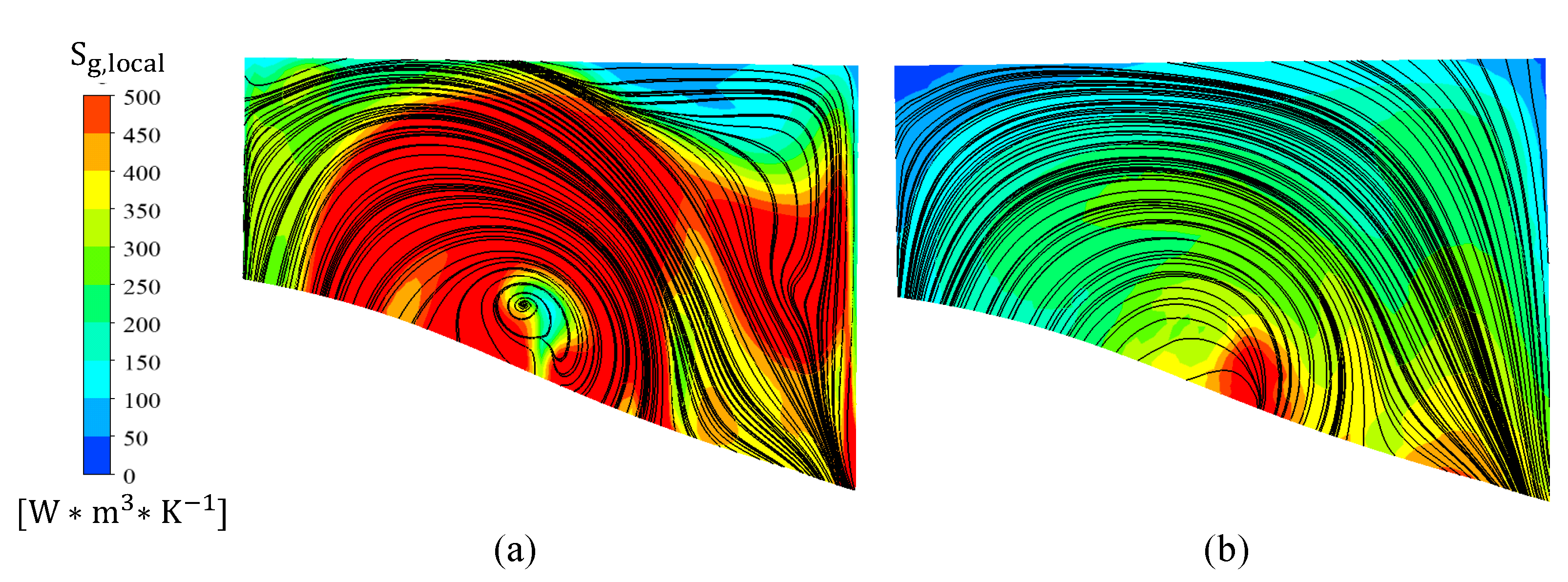
3.2. Entropy Generation Analysis

As mentioned previously, the combination of CTs can energize the low-energy fluid in the corner area by the injection, so that the flow separation is suppressed with decreased blockage near the tip. However, the interaction of such combination is still unclear. In order to better explain the effect of CCT, and analyze the loss mechanism at the same time, an analysis of entropy generation is performed in this section.
The whole passage is taken as a control volume and based on the derivation in Ref. [40]; the entropy generation in the compressor can be described as follows:
S ˙ g , l o c a l = k T 2 T ¯ z T ¯ z + α t α k T 2 T ¯ z T ¯ z + 2 μ s i j ¯ s i j ¯ T ¯ + ε ρ ¯ T ¯
where α t is the turbulent thermal conductivity, “   ¯   ” means the numerical Reynolds averaged parameters, k is thermal conductivity, T is local temperature of fluid, μ is fluid dynamic viscosity, s i j is shear strain rate, ρ is density and ε is turbulent dissipation rate.

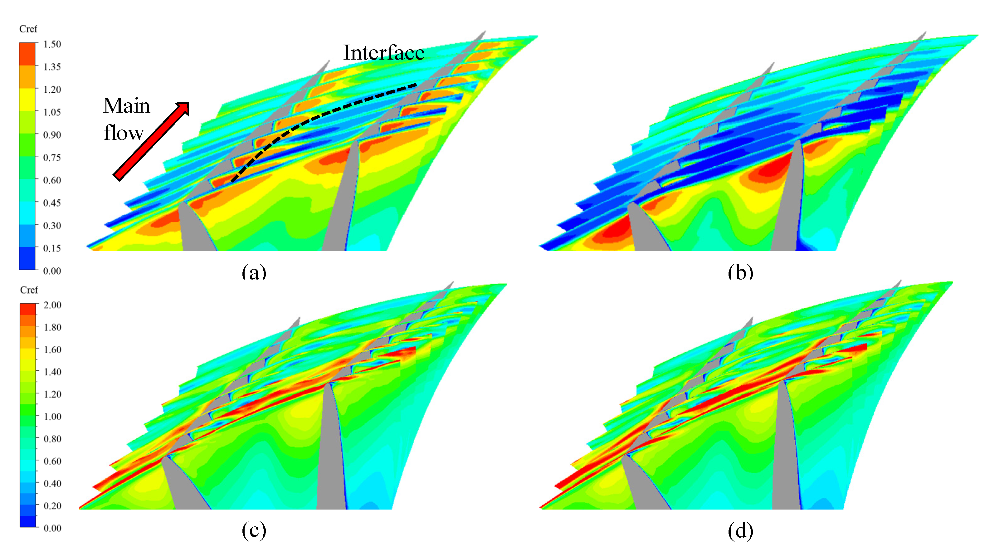
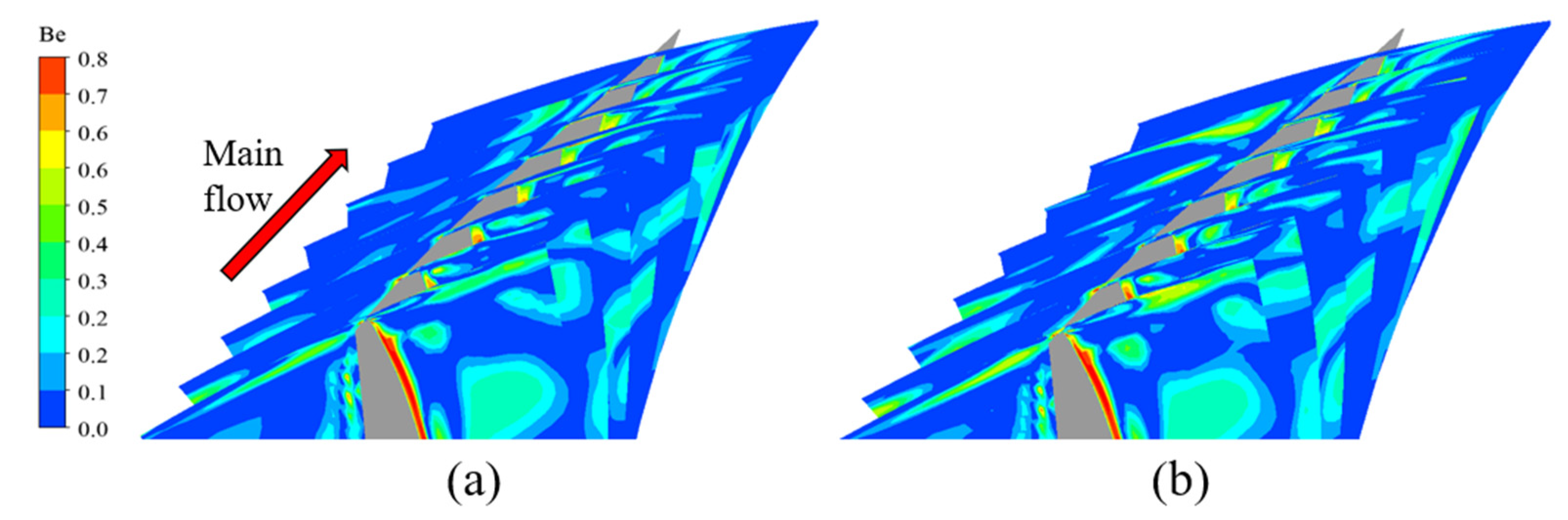
3.2.1. Analysis of Exchange Flow

Actually, it has been well accepted that the stabilization effects of the slot mainly de-pend on the exchange flow [1,14,37]. In order to analyze whether the superior performance of CCT is related to this inherent characteristic, Figure 10 shows a comparison of contour of S ˙ g , l o c a l and backward streamline in the slot. It is significant that the fluid is driven through the slots by the pressure gradient and forms an exchange flow. However, vortex cores appear in the slot and blockage occurs near the wall in Figure 10a; the strong shear force brings about large entropy production in the slot. In addition, the friction loss is also increased due to the vertical injection of slots to the main flow; hence, the efficiency penalty increases in Figure 5. In Figure 10b, as mentioned before, the excess flow near the tip is decreased by injection. As a result, the whole passage of the slot in CCT scheme is found to be involved in the exchange flow with no blockage. The original vortex core in the slot disappears with low entropy generation rate, suggesting the better effect of CCT for stability improvement due to the strengthened exchange flow.

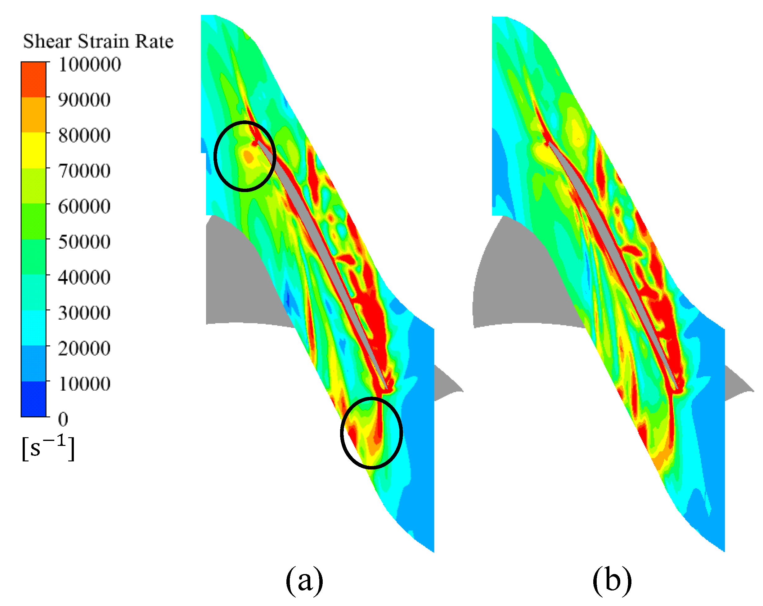
3.2.2. Analysis of Loss Mechanism

Generally, the entropy generation loss can be attributed to the heat transfer and fluid friction [40], and it is essential to ascertain the relative dominance of entropy generation, i.e., the loss mechanism in order to give guidance on CT design. A dimensionless parameter, Bejan number (Be), is defined as follows [41]:
B e = S ˙ g , h e a t S ˙ g , l o c a l
where S ˙ g , h e a t represents the entropy generation due to heat transfer. Thus, Be > 0.5 implies dominance of heat transfer irreversibility and vice versa.
The contours of Be in the tip region of the two schemes are shown in Figure 11. The Be number increases obviously near the blade tip along the main flow, indicating that the share of loss caused by heat transfer increases due to the injection. Nevertheless, the flow loss is still dominated by fluid friction. Considering that shear strain rate (SSR) can indicate the entropy generation from friction qualitatively [42], contours of SSR at 98% span are depicted in Figure 12. The shrinkage of high SSR region at the leading and trailing edge can be observed in CCT scheme, owing to the enhancement of exchange flow. What is more, the high SSR region is dispersed due to the suppression of vortex formation. Thus, the fluid friction attenuates accordingly manifesting the variation in Be. As a result, the entropy generation decreases because of the reduction in friction loss, which is consistent with the analysis of exchange flow.

3.2.3. Analysis of Loss Quantification

Furthermore, as shown in Figure 13, the whole passage is divided into three parts, including upper section, lower section and main flow section, in order to evaluate their contribution to the total loss. The loss for each single domain is calculated according to Equation (4). To compare the improvement effect of SES and CCT on loss generation, the relative variation of loss is defined as follows:
Δ L = L O R I L L O R I
where L O R I represents the loss of ORI scheme and L represents the loss of CCT or SES scheme.
The total loss contributions of each control volume are shown in Figure 14. Apparently, the major source of entropy generation comes from the main flow, occupying nearly half of the proportion. From Figure 14b, the utilization of axial skewed slots in SES significantly reduces the proportion of lower region, while the proportion of upper region increases due to the mixing loss brought by exchange flow. The effect of CCT mainly concentrates in decreasing the loss in upper region by contrast with the SES scheme, see Figure 14c. It can be explained by the previous analysis that the enhanced exchange flow reduces the entropy generation. Moreover, the loss of lower region in CCT scheme is further decreased, since the mass flow there is replenished near the corner and the flow separation is suppressed.
From Table 2, in regard to the total loss, the CCT scheme has a better effect of improvement by 2.65% compared with SES, consistent with the previous results. In addition, it is obvious that, though the loss in the lower part of the blade increases because of the addition of injection groove, the decrement of loss in the upper region plays the most important role for total loss. In short, a better control effect is obtained through the combination of these two CT configurations.

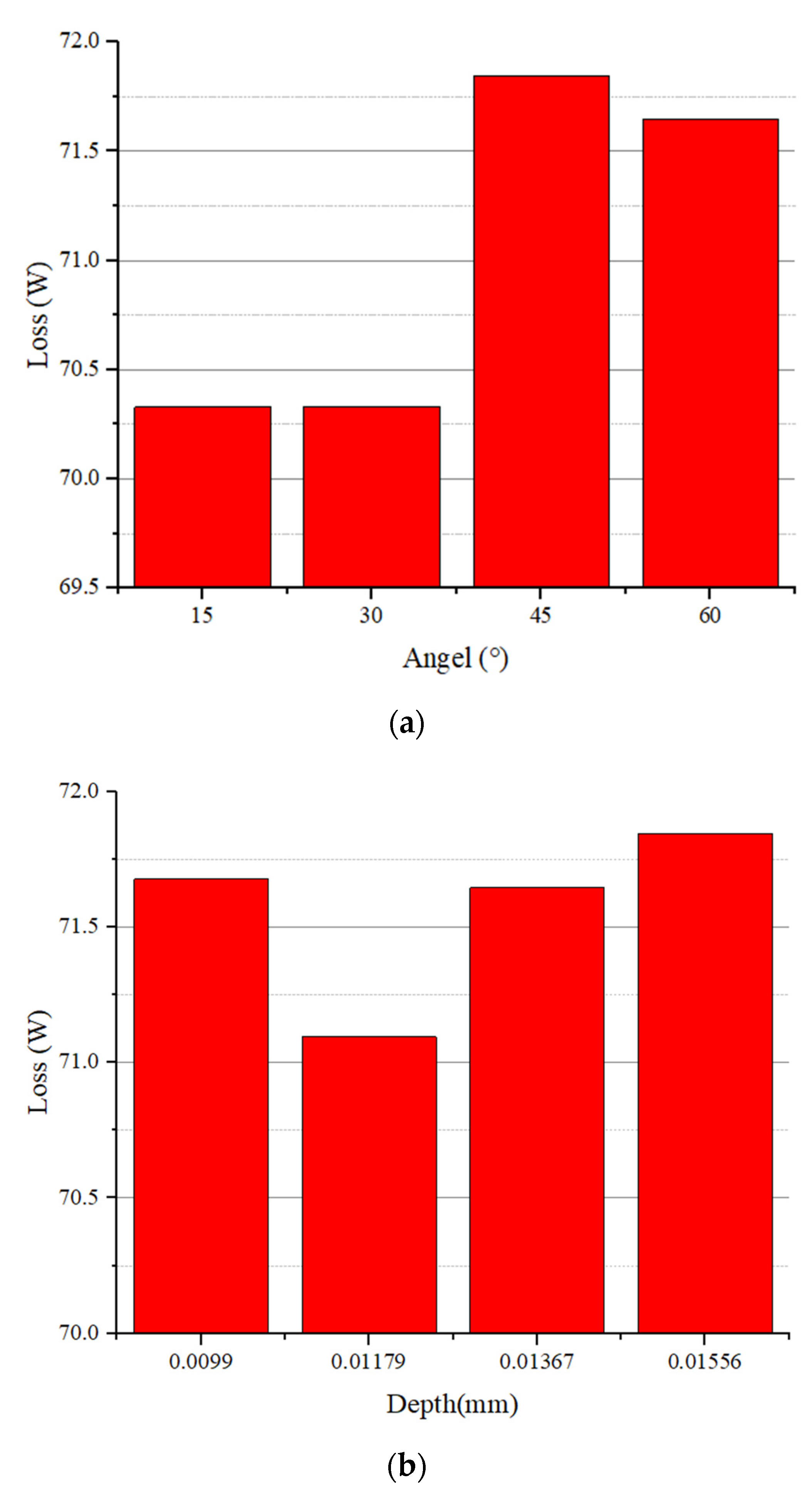
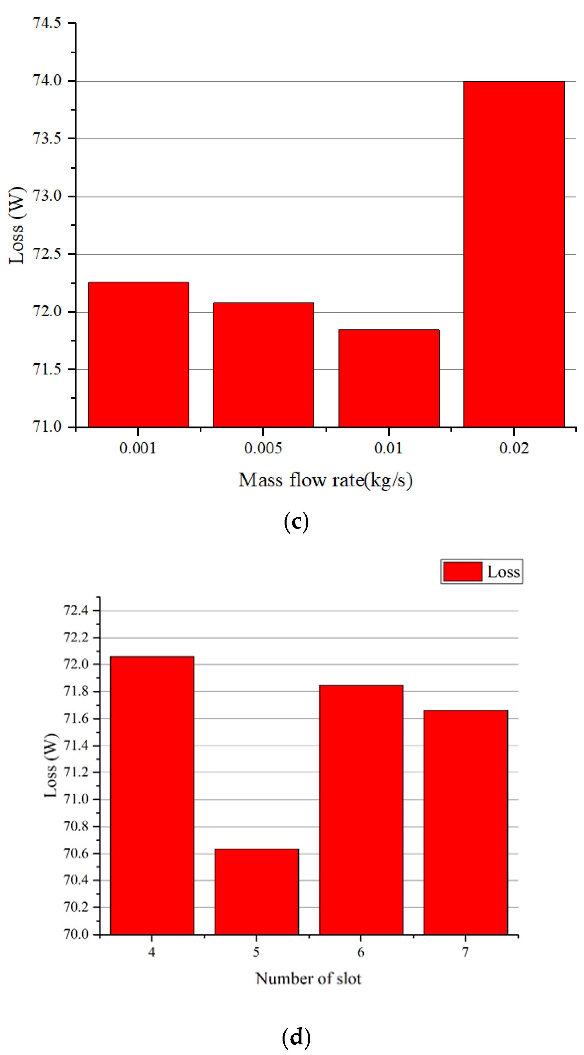
3.2.4. Parameter Analysis

The influence of geometry parameters has been studied previously [21,22] and some general conclusions can be drawn that the effectiveness and efficiency of the slot casing treatments relied much on the position of the slots, and the coverage of slots should include the leak vortex for optimal effect. It is essential to re-evaluate the coupling effect between parameters of CCT considering the strengthened exchange flow and eliminated corner vortex.
In this section, four parameters, i.e., angel of slot, depth of slot, slot number and mass flow rate of injection, are selected for parametric study on the total loss in the passage. The compressor is operated at design point and the result is depicted in Figure 15. From Figure 15a, the total loss maximizes when the angle is 45° and tends to be stable as the angle further increases. Actually, the larger the angle is, the more difficult for the exchange flow to form, and the structural obstruction may cause more mixing loss. On the other hand, the total loss minimizes when the depth is 0.01179 mm in Figure 15b. Considering the variation of depth can affect the exchange flow rate in the slot, it could be deduced that the slots whose exchange flow rate equals the injection mass-flow rate have the best effect of loss reduction, in which case the injection can just supplement the blade root fluid without the blockage. In other words, excessive exchange flow will cause greater fluid friction, while insufficient exchange flow is incapable of eliminating the blockage.
A similar inference can be made from Figure 15c that the total loss minimizes when the mass flow rate is 0.01 kg/s. It can be explained that the exchange flow is constant for a series of determined parameters of slots, and the fluid migrated from the lower part of the blade could not be sucked away in time with the excessive injection. Thus, the fluid will accumulate at the blade tip and increase the mixing loss. On the contrary, the blockage occurs near the blade tip with insufficient injection. What is more, it can also be concluded that the mixing loss caused by injection is much higher than that by blockage. The loss increases with slot number first and then decreases, see Figure 15d. Due to the constant area ratio of slot, the change in slot number is expected to have limited effect on total exchange flow rate. However, Liu et. al [43] found that the characteristic frequency of the axial skewed slots changes with the slot number. It achieved optimum effect of stability enhancement when the characteristic frequency approaches the forecasting fluctuating frequency of tip leakage vortex. Accordingly, the loss minimum is at 5 in this paper.

4. Conclusions

A novel CT structure combining axial skewed slots and injection is proposed in this paper. A NASA 67 rotor with different CT schemes, including the novel one, are compared on the aerodynamic performance, as well as the mechanisms of loss generation by numerical analysis. As a result, the combined CT successfully couples the flow control effects of the axial skewed slots and the injection groove. The following conclusions could be drawn:
(1) The novel CT structure increases the SM of the rotor by 14.7%, greatly expanding the stable operating range, with low efficiency penalty of 1.12%. The growth of the separation vortex at the trailing edge is further restrained and the overall velocity near the tip increases. In addition, for the lower part of the blade, the low-velocity flow is energized by injection, exhibiting the disappearance of vortex.
(2) The superior flow control of novel CT can be attributed to the interaction between the two structures, which strengthens the exchange flow in the slots and suppresses the radial motion of fluid. Though the flow loss is still dominated by fluid friction through loss generation analysis, the intensity has been decreased after the utilization of novel CT.
(3) Through the parametric analysis on the angle of slot, depth of slot, slot number and mass flow rate of injection of the novel CT, the total loss maximizes when the angle is 45° and tends to be stable as the angle further increases. In addition, it could be deduced that the slots whose exchange flow rate equals the injection mass-flow rate have the best effect of loss reduction. Moreover, the loss minimum when the slot number is set with the characteristic frequency approaches the forecasting fluctuating frequency of tip leakage vortex. In other words, the best control effect needs the match between the geometrical parameter of axial skewed slots and mass-flow rate of injection.

Author Contributions

Conceptualization, J.-X.L. and F.-S.Y.; methodology, J.-X.L.; software, J.-X.L. and T.-Q.H.; validation, J.-X.L., F.-S.Y. and T.-Q.H.; formal analysis, J.-Q.D.; investigation, J.-X.L.; resources, J.-Q.D.; data curation, T.-Q.H.; writing—original draft preparation, J.-X.L. and T.-Q.H.; writing—review and editing, F.-S.Y. and Z.-X.Z.; visualization, J.-X.L.; supervision, Z.-X.Z.; project administration, F.-S.Y.; funding acquisition, J.-Q.D. All authors have read and agreed to the published version of the manuscript.

Funding

This research was funded by National Key R&D Program of China (NO. 2017YFB0903600).

Institutional Review Board Statement

Not applicable.

Informed Consent Statement

Not applicable.

Data Availability Statement

Not applicable.

Acknowledgments

The author expresses his gratitude and acknowledges continuous support from academic supervisors Fu-Sheng Yang and Jian-Qiang Deng.

Conflicts of Interest

The authors declare no conflict of interest.

Nomenclature

η i n modified efficiency
W a required isentropic compression work, J
Wactual work done, J
P o u t outlet pressure, Pa
P i n inlet pressure, Pa
γ specific heat ratio
T i n inlet temperature, K
T o u t outlet temperature, K
T i temperature of the injection, K
m i n mass flow rate of inlet, kg /s
m o u t mass flow rate of outlet, kg /s
m i mass flow rate of injection, kg /s
π N S * pressure ratio near the stall point
m N S * mass flow rate near the stall point
π N P E * pressure ratio near the peak efficiency point
m N P E * flow rate near the peak efficiency point
C r e f relative total pressure coefficient
P r t relative total pressure, Pa
P r e f reference pressure, Pa
ρ density of the fluid, kg   m 3
U t i p speed of the blade tip, m   s 1

References

  1. Sun, X.; Dong, X.; Sun, D. Recent development of casing treatments for aero-engine compressors. Chin. J. Aeronaut. 2019, 32, 1–36. [Google Scholar] [CrossRef]
  2. Wennerstrom, A.J. Highly Loaded Axial Flow Compressors: History and Current Developments. J. Turbomach. 1990, 112, 567–578. [Google Scholar] [CrossRef]
  3. Hergt, A.; Meyer, R.; Engel, K. Effects of Vortex Generator Application on the Performance of a Compressor Cascade. ASME J. Turbomach. 2013, 135, 021026.1–021026.10. [Google Scholar] [CrossRef]
  4. Benini, E.; Biollo, R.; Ponza, R. Efficiency enhancement in transonic compressor rotor blades using synthetic jets: A numerical investigation. Appl. Energy 2011, 88, 953–962. [Google Scholar] [CrossRef]
  5. Ding, J.; Chen, S.; Xu, H.; Sun, S.J.; Wang, S.T. Control of Flow Separations in Compressor Cascade by Boundary Layer Suction Holes in Suction Surface. In Proceedings of the ASME Turbo Expo 2013: Turbine Technical Conference and Exposition, San Antonio, TX, USA, 3–7 June 2013; Volume 6A, Turbomachinery. pp. 35–52. [Google Scholar] [CrossRef]
  6. Tang, M.; Jin, D.; Gui, X. Modeling and numerical investigation of the inlet circumferential fluctuations of swept and bowed blades. J. Therm. Sci. 2017, 26, 1–10. [Google Scholar] [CrossRef]
  7. Houghton, T.; Day, I. Stability Enhancement by Casing Grooves: The Importance of Stall Inception Mechanism and Solidity. ASME J. Turbomach. 2012, 134, 021003.1–021003.8. [Google Scholar] [CrossRef]
  8. Chu, W.; Li, X.; Wu, Y.; Zhang, H. Reduction of end wall loss in axial compressor by using non-axisymmetric profiled end wall: A new design approach based on end wall velocity modification. Aerosp. Sci. Technol. 2016, 55, 76–91. [Google Scholar] [CrossRef]
  9. Benhegouga, I.; Yang, C. Numerical Simulation of Steady Air Injection Flow Control Effects on a Transonic Axial Flow Compressor. Appl. Mech. Mater. 2012, 224, 352–357. [Google Scholar] [CrossRef]
  10. Mao, X.C.; Liu, B.; Cao, Z.Y.; Zhang, P. Research on Corner Separation Control for Compressor Cascade with End-Wall Jet Flow. J. Propuls. Technol. 2014, 35, 1615–1622. [Google Scholar] [CrossRef]
  11. Li, J.; Du, J.; Geng, S.; Li, F.; Zhang, H. Tip air injection to extend stall margin of multi-stage axial flow compressor with inlet radial distortion. Aerosp. Sci. Technol. 2020, 96, 105554. [Google Scholar] [CrossRef]
  12. Yang, Q.; Li, L.; Zhao, Y.; Xiao, J.; Shu, Y.; Zhang, Q. Experimental investigation of an active control casing treatment of centrifugal compressors. Exp. Therm. Fluid Sci. 2017, 83, 107–117. [Google Scholar] [CrossRef]
  13. Wilke, I.; Kau, H. A Numerical Investigation of the Flow Mechanisms in a HPC Front Stage with Axial Slots. ASME J. Turbomach. 2004, 126, 339–349. [Google Scholar] [CrossRef]
  14. Danner, F.C.T.; Kau, H.P.; Mu¨ller, M.M.; Schiffer, H.P.; Brignole, G.A. Experimental and Numerical Analysis of Axial Skewed Slot Casing Treatments for a Transonic Compressor Stage. In Proceedings of the ASME Turbo Expo 2009: Power for Land, Sea, and Air, Orlando, FL, USA, 8–12 June 2009; Volume 7, Turbomachinery, Parts A and B. pp. 227–238. [Google Scholar] [CrossRef]
  15. Cravero, C.; Leutcha, P.J.; Marsano, D. Simulation and Modeling of Ported Shroud Effects on Radial Compressor Stage Stability Limits. Energies 2022, 15, 2571. [Google Scholar] [CrossRef]
  16. He, X.; Zheng, X. Roles and mechanisms of casing treatment on different scales of flow instability in high pressure ratio centrifugal compressors. Aerosp. Sci. Technol. 2019, 84, 734–746. [Google Scholar] [CrossRef]
  17. Zhang, H.G.; Chu, W.L.; Wu, Y.H. Mechanism of Influences of Axial Positions of Axial Skewed Slot CT on a Compressor Performance. J. Aerosp. Power 2011, 26, 92–98. [Google Scholar]
  18. Zhang, H.G.; Chu, W.L.; Wu, Y.H.; Deng, W.J.; Zhang, X. Mechanism of stall margin improvement associated with the blowing circumferential grooved casing treatment. J. Aerosp. Power 2007, 22, 961–966. [Google Scholar]
  19. Kim, D.W.; Kim, J.H.; Kim, K.Y. Parametric Study on Aerodynamic Performance of a Transonic Axial Compressor with a Casing Groove and Tip Injection. Appl. Mech. Mater. 2013, 284–287, 872–877. [Google Scholar] [CrossRef]
  20. Kim, J.-H.; Kim, D.-W.; Kim, K.-Y. Aerodynamic optimization of a transonic axial compressor with a casing groove combined with tip injection. Proc. Inst. Mech. Eng. Part A J. Power Energy 2013, 227, 869–884. [Google Scholar] [CrossRef]
  21. Dinh, C.-T.; Heo, M.-W.; Kim, K.-Y. Aerodynamic performance of transonic axial compressor with a casing groove combined with blade tip injection and ejection. Aerosp. Sci. Technol. 2015, 46, 176–187. [Google Scholar] [CrossRef]
  22. Fujita, H.; Takata, H. A Study on Configurations of Casing Treatment for Axial Flow Compressors. Bull. JSME 1984, 27, 1675–1681. [Google Scholar] [CrossRef] [Green Version]
  23. Koch, C.C.; Smith, L.H., Jr. Loss Sources and Magnitudes in Axial-Flow Compressors. J. Eng. Power 1976, 98, 411–424. [Google Scholar] [CrossRef]
  24. Sun, Y.; Ren, Y. Simulation and unsteady loss analyses of the flow in single-stage transonic compressor. Tsinghua Univ. (SciTech) 2009, 49, 759–762. [Google Scholar]
  25. Xi, N.; Le, L.; Ning, M.; Qian, L.; Feng, L. Numerical Investigation of Entropy Generation Distributions in a Transonic Compressor. In Proceedings of the ASME Turbo Expo 2016: Turbomachinery Technical Conference and Exposition, Seoul, Korea, 13–17 June 2016. [Google Scholar]
  26. Mu¨ller, M.W.; Schiffer, H.P.; Voges, M.; Hah, C. Investigation of Passage Flow Features in a Transonic Compressor Rotor With Casing Treatments. In Proceedings of the ASME 2011 Turbo Expo: Turbine Technical Conference and Exposition, Vancouver, BC, Canada, 6–10 June 2011; Volume 7, Turbomachinery, Parts A, B, and C. pp. 65–75. [Google Scholar] [CrossRef]
  27. Strazisar, A.J.; Wood, J.R.; Hathaway, M.D.; Suder, K.L. Laser anemometer measurements in a transonic axial-flow fan rotor. NASA Tech. Pap. 1989, NAS 1.60, 2879. [Google Scholar]
  28. Liu, Z.W.; Zhang, C.S.; Shi, J.X.; Wang, Z.S.; Huang, J.G. A study on effects of axial positions of skewed slots CT on compressor performance. J. Eng. Thermophys. 1987, 8, 52–54. [Google Scholar]
  29. Du, J.; Lin, F.; Zhang, H.; Chen, J. Numerical investigation on the self-induced unsteadiness in tip leakage flow for a transonic fan rotor. ASME J. Turbomach 2010, 132, 021017.1–021017.9. [Google Scholar] [CrossRef]
  30. Prince, D.C.; Wisler, D.D.; Hilvers, D.E. A Study of Casing Treatment Stall Margin Improvement Phenomena. In Turbo Expo: Power for Land, Sea, and Air, Proceedings of the ASME 1975 International Gas Turbine Conference & Products Show, Houston, TX, USA, 2–6 March 1975; American Society of Mechanical Engineers: New York, NY, USA, 1975. [Google Scholar] [CrossRef] [Green Version]
  31. Liu, J.X.; Yang, F.S.; Deng, J.Q.; Zhang, Z.X. Influence of Combined Casing Treatment on Flow Characteristics of Transonic Compressor. J. Xi’an Jiaotong Univ. 2020, 54, 173–178. [Google Scholar] [CrossRef]
  32. Wang, S.T.; Qiang, X.Q.; Feng, G.T.; Lin, W.C.; Wang, Z.Q. Study of low-reaction boundary layer suction axial compressor and it’s internal flow control. J. Eng. Thermophys. 2009, 30, 35–40. [Google Scholar]
  33. Ba, D.; Zhang, Q.; Du, J.; Li, Z.; Zhang, H.; Nie, C. Design optimization of axial slot casing treatment in a highly-loaded mixed-flow compressor. Aerosp. Sci. Technol. 2020, 107, 106262. [Google Scholar] [CrossRef]
  34. Lu, X.G.; Chu, W.L.; Zhu, J.Q.; Wang, R.G. Experimental and Numerical Investigation of a Subsonic Compressor with Bend Skewed Slots Casing Treatment. In Proceedings of the ASME Turbo Expo 2006: Power for Land, Sea, and Air, Barcelona, Spain, 8–11 May 2006. [Google Scholar]
  35. Chen, J.P.; Hathaway, M.D.; Herrick, G.P. Pre-stall behavior of a transonic axial compressor stage via time-accurate numerical simulation. J. Turbomach 2008, 130, 041014. [Google Scholar] [CrossRef] [Green Version]
  36. Brandstetter, C.; Wartzek, F.; Werner, J.; Schiffer, H.-P.; Heinichen, F. Unsteady Measurements of Periodic Effects in a Transonic Compressor with Casing Treatments. J. Turbomach. 2016, 138, 051007.1–051007.9. [Google Scholar] [CrossRef]
  37. Zhang, Q.; DU, J.; Li, J.; Zhao, M.; Zhang, H. Dual stability enhancement mechanisms of axial-slot casing treatment in a high-speed mixed-flow compressor with various tip clearances. Chin. J. Aeronaut. 2020, 34, 19–31. [Google Scholar] [CrossRef]
  38. Fan, L. Stall of an axial-compressor rotor with casing treatment. J. Aerosp. Power 2015, 30, 2647–2657. [Google Scholar] [CrossRef]
  39. Wu, W.; Zhao, J.; Zhong, J. Influence of the rotating direction and speed of controllable speed casing on the flow stability of a transonic compressor rotor under design condition. Aerosp. Sci. Technol. 2022, 126, 1270–9638. [Google Scholar] [CrossRef]
  40. Zhang, Q.; Du, J.; Li, Z.; Li, J.; Zhang, H. Entropy Generation Analysis in a Mixed-Flow Compressor with Casing Treatment. J. Therm. Sci. 2019, 28, 915–928. [Google Scholar] [CrossRef]
  41. Basak, T.; Singh, A.K.; Sruthi, T.A.; Roy, S. Finite element simulations on heat flow visualization and entropy generation during natural convection in inclined square cavities. Int. Commun. Heat Mass Transf. 2014, 51, 1–8. [Google Scholar] [CrossRef]
  42. Denton, J.D. Loss Mechanisms in Turbomachines; American Society of Mechanical Engineers: New York, NY, USA, 1993; Volume 78897, p. V002T14A001. [Google Scholar]
  43. Liu, R.Y.; Hou, A.P. Unsteady numerical study on flow control of axial skewed slots on compressor tip leakage vortex. Math. Comput. Model. 2019, 32, 8–15. [Google Scholar]
Figure 1. Geometric design of NASA rotor 67.
Energies 15 05066 g001
Figure 2. Geometry of (a) axial skewed slots and (b) injection groove.
Energies 15 05066 g002
Figure 3. Computational domain and grids.
Energies 15 05066 g003
Figure 4. Comparison of computed and measured adiabatic efficiency characteristic.
Energies 15 05066 g004
Figure 5. Comparison of performance curves.
Energies 15 05066 g005
Figure 6. Streamlines at the blade tip. (a) ORI; (b) SES; (c) SEI; (d) CCT.
Energies 15 05066 g006
Figure 7. Contours of Mach number at 98% span. (a) ORI; (b) SES; (c) SEI; (d) CCT.
Energies 15 05066 g007
Figure 8. Contours of relative total pressure coefficient. (a) ORI; (b) SEI; (c) SES; (d) CCT.
Energies 15 05066 g008
Figure 9. Limiting streamline of two schemes. (a) SES; (b) CCT.
Energies 15 05066 g009
Figure 10. Backward streamlines and entropy contours of the slot near the stall condition. (a) SES; (b) CCT.
Energies 15 05066 g010
Figure 11. Contours of Be number in the tip region. (a) SES; (b) CCT.
Energies 15 05066 g011
Figure 12. Contours of shear strain rate at 98% span. (a) SES; (b) CCT.
Energies 15 05066 g012
Figure 13. Schematic drawing of control volumes.
Energies 15 05066 g013
Figure 14. Comparison of proportion distribution of each region. (a) ORI; (b) SES; (c) CCT.
Energies 15 05066 g014
Figure 15. Results of parametric study on total loss. (a) Angle of slot; (b) depth of slot; (c) mass flow rate of injection; (d) number of slots.
Energies 15 05066 g015aEnergies 15 05066 g015b
Table 1. Basic parameters of axial skewed slots.
ParametersValue
Depth11 mm
Width3 mm
Number of slots6
Area ratio of slot50%
Skewed angle45°
Table 2. Relative variation in loss.
UpDownMainSum
SES−17.54%17.93%6.93%2.53%
CCT−14.46%18.49%5.19%2.65%
Publisher’s Note: MDPI stays neutral with regard to jurisdictional claims in published maps and institutional affiliations.

