
Selecting and Testing of Cement-Bonded Magnetite and Chalcopyrite as Oxygen Carrier for Chemical-Looping Combustion


Abstract
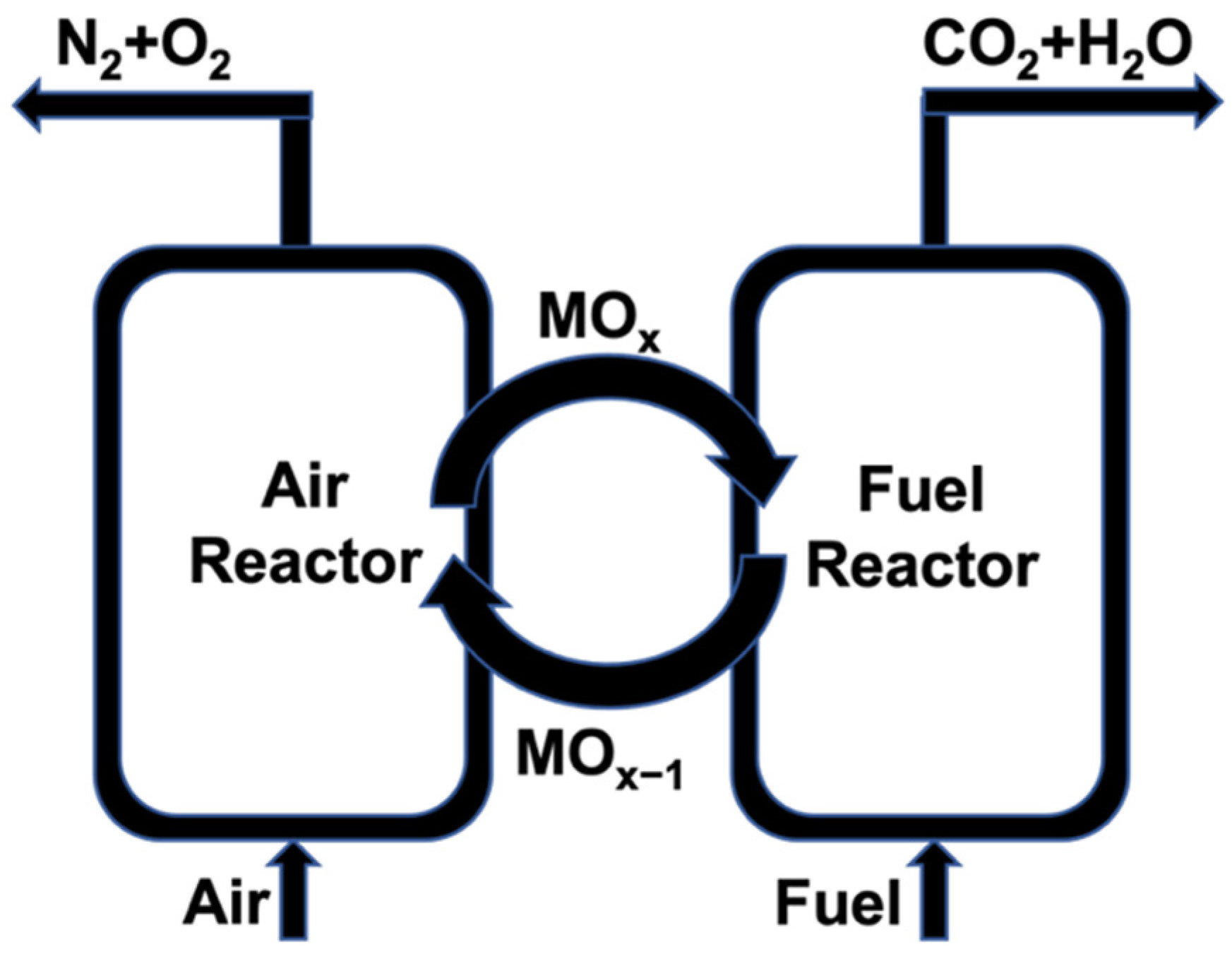
:1. Introduction
2. Experimental Section
2.1. Characterization Techniques
2.2. The Magnetite, Chalcopyrite, and Cements
2.3. Cement-Bonded Magnetite-Chalcopyrite Samples
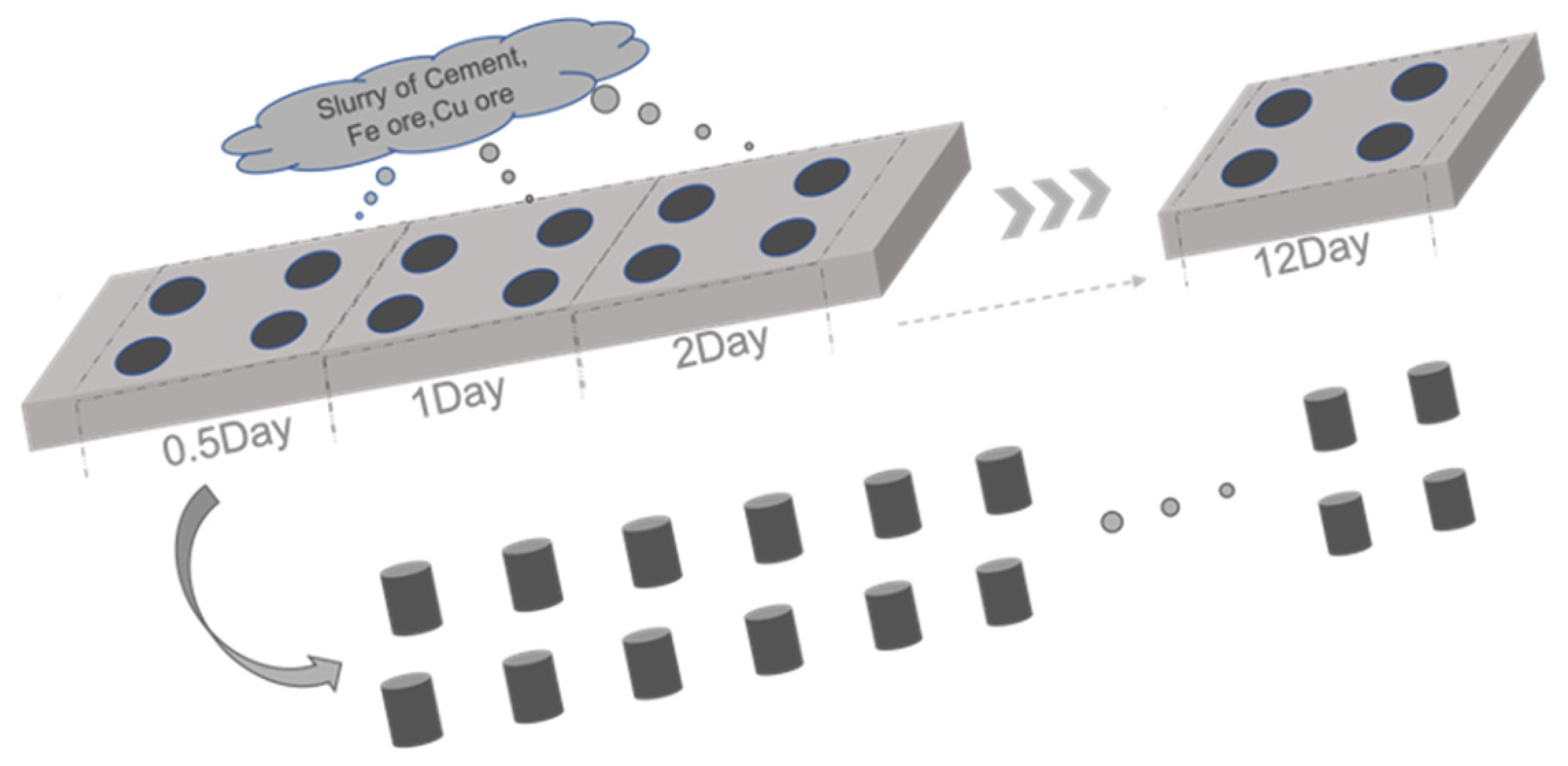
2.3.1. Cylinder Samples for Preliminary Selection
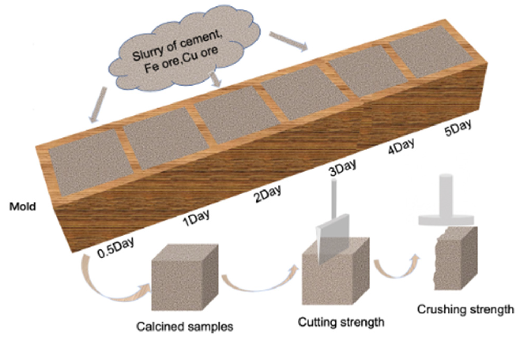
2.3.2. Cubic Samples for Secondary Selection
2.4. The CA70-Cement-Bonded Oxygen Carrier
2.5. Batch-Fluidized Bed Experiments
3. Data Evaluation
4. Results and Discussion
4.1. Screening of the Cement Binder
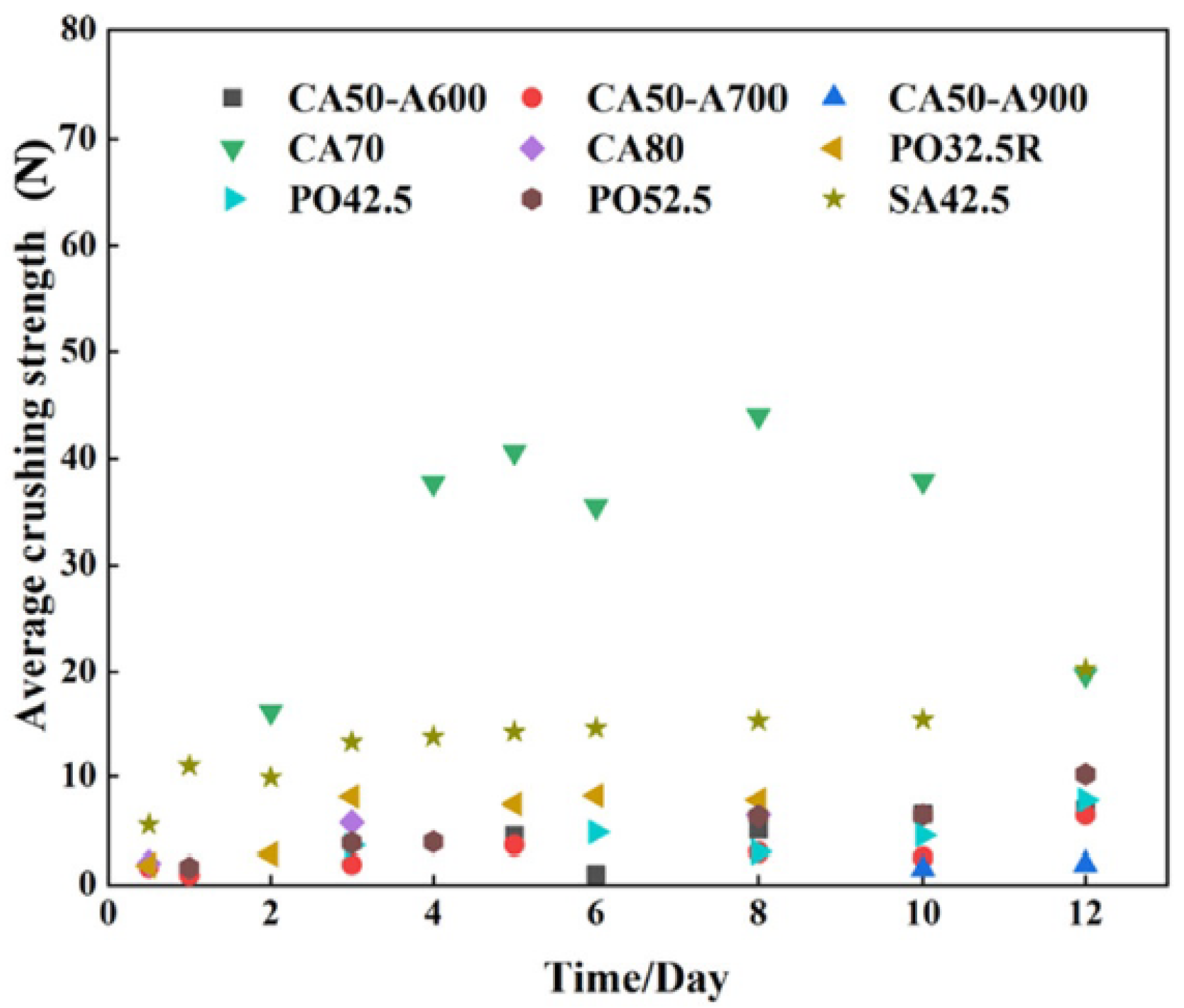
4.1.1. Crushing Strength of the Cylindrical Samples
4.1.2. Cement Selection Based on Cubic Samples
Cutting and Crushing Strength of the Cubic Samples
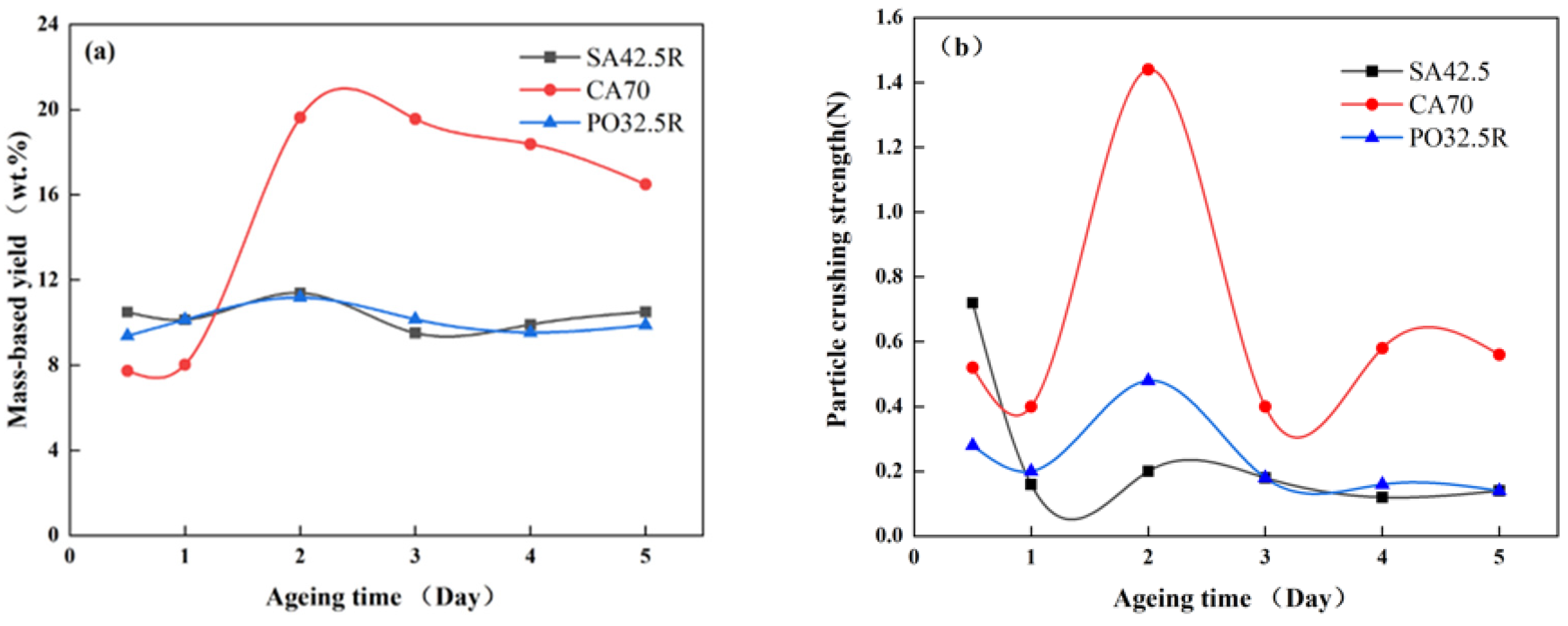
Particle Yield and Particle Crushing Strength
4.1.3. Reactivity Comparison in TGA
4.2. Performance of Oxygen Carrier in the Batch Reactor
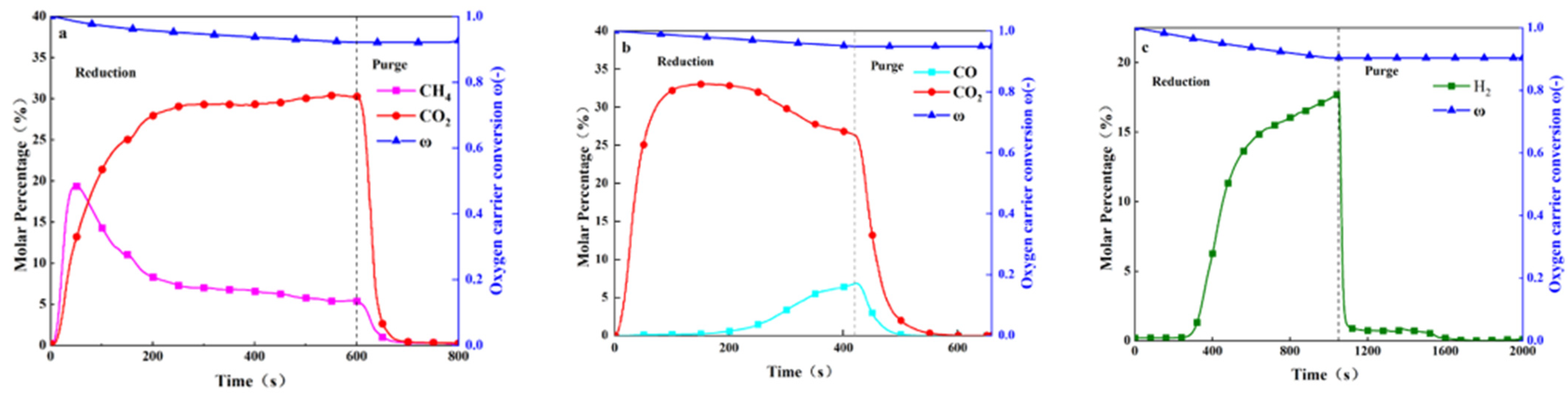
4.2.1. Reaction Progress with CH4, CO, and H2
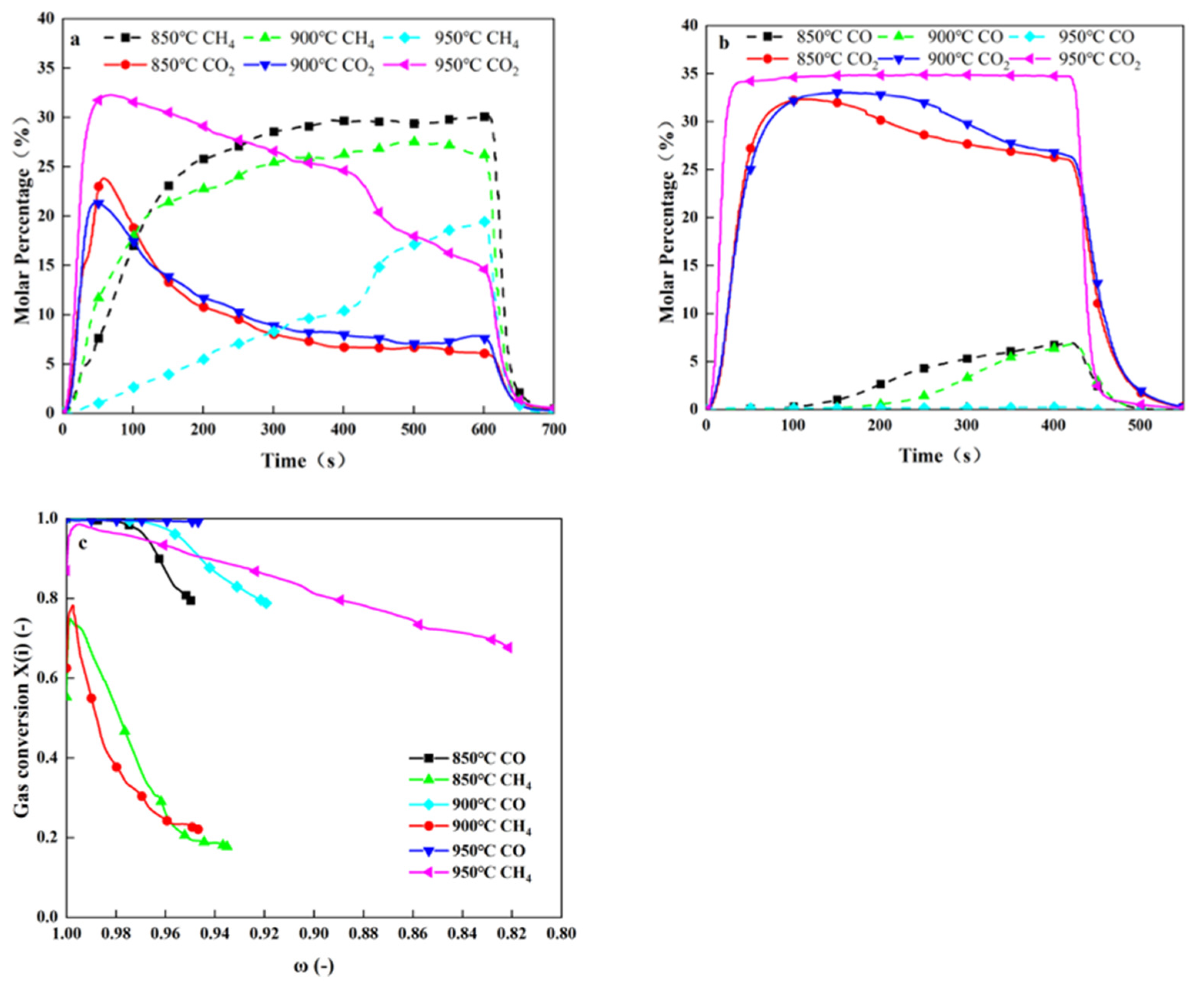
4.2.2. Influence of Temperature
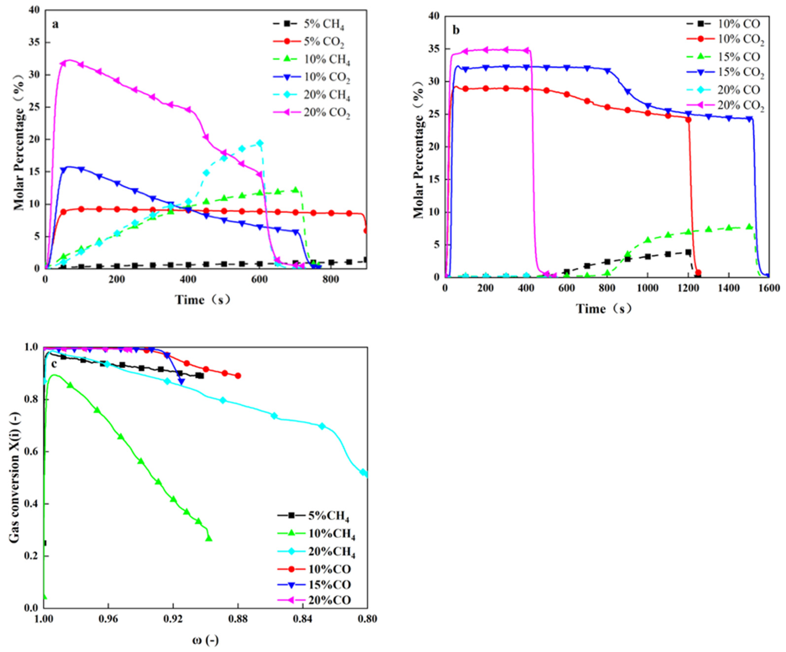
4.2.3. Influence of Fuel Concentration
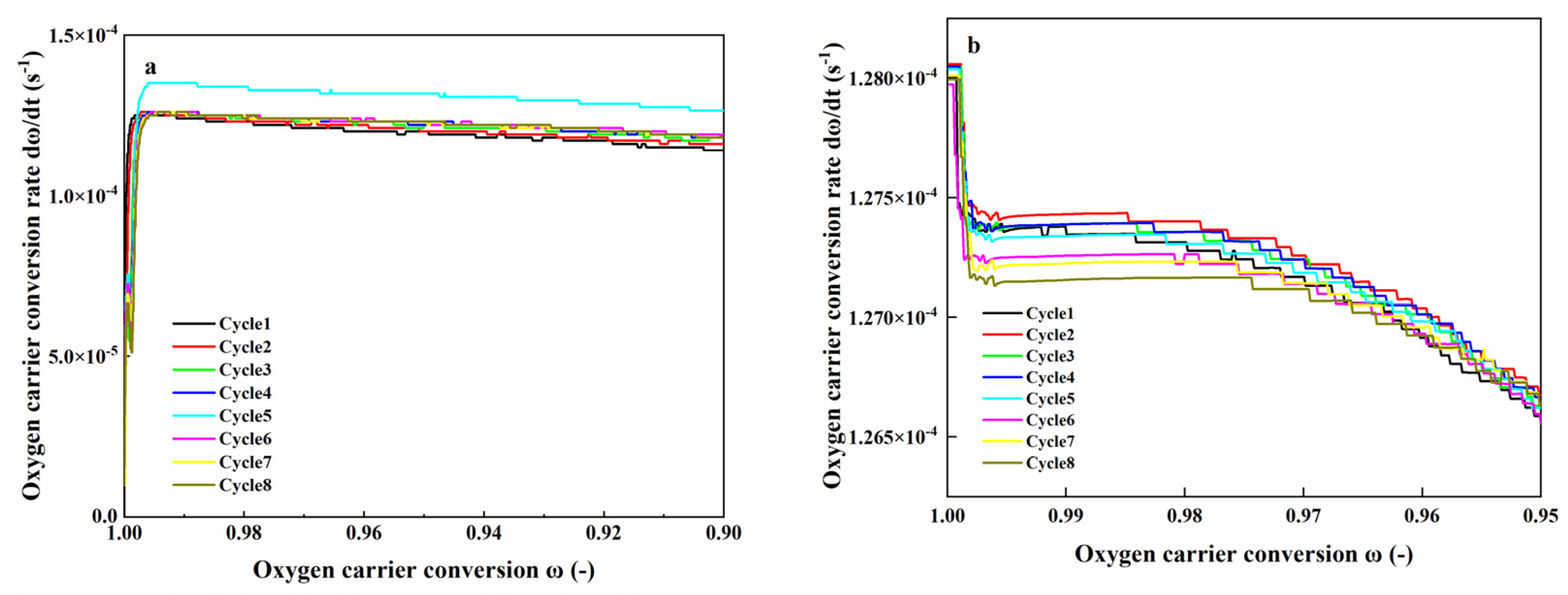
4.2.4. Cyclic Stability of the CA70-Bonded Oxygen Carrier
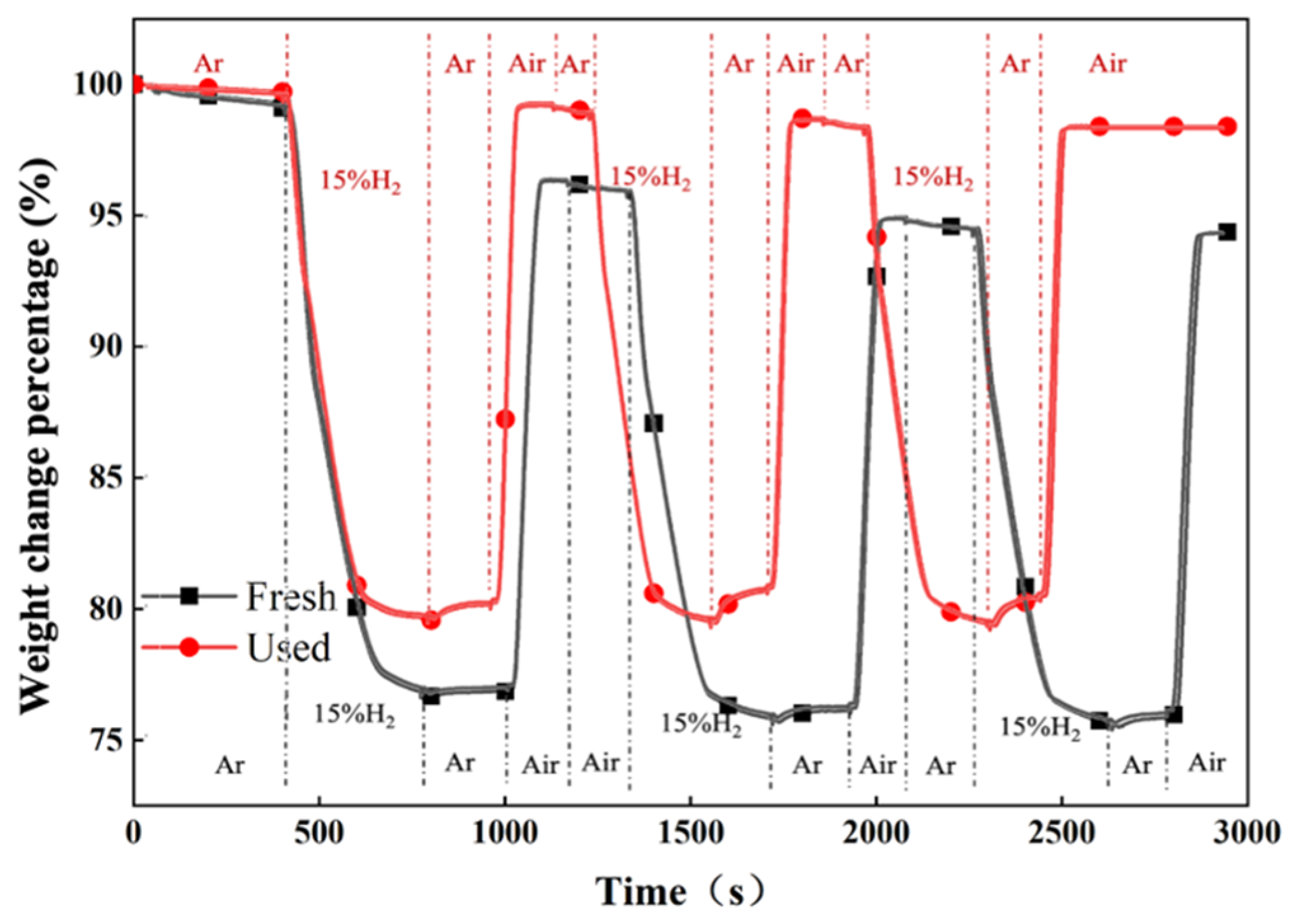
4.3. Thermogravimetric Analysis for Fresh and Used Oxygen Carrier
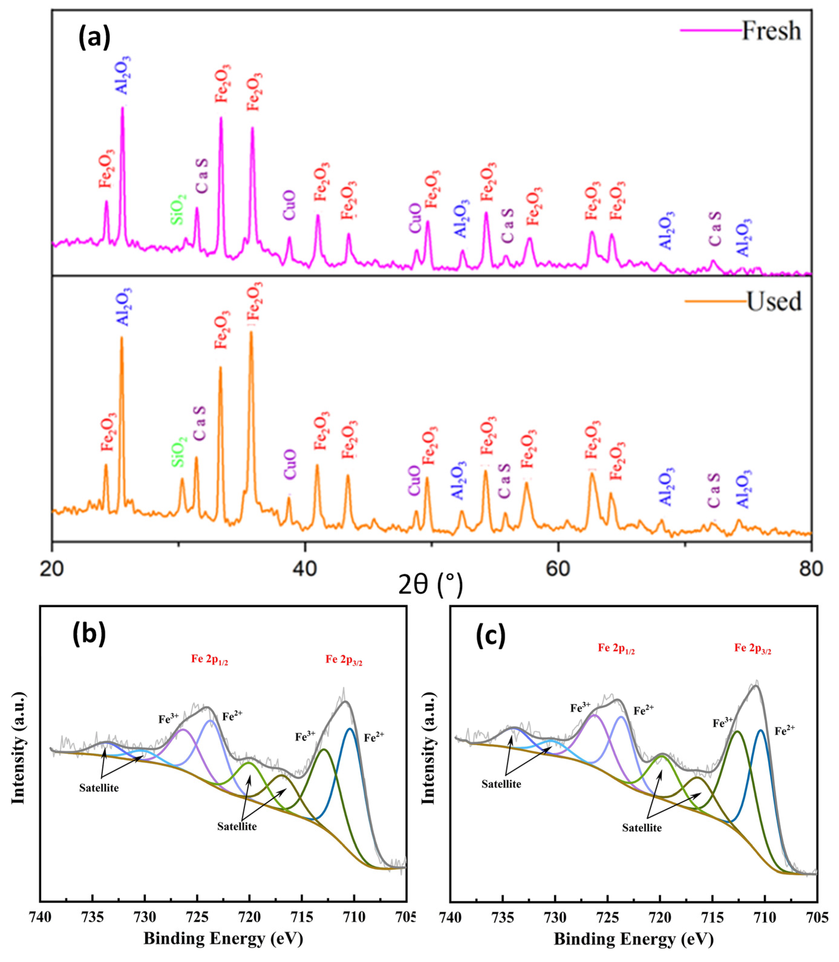
4.4. XRD and XPS Analyses
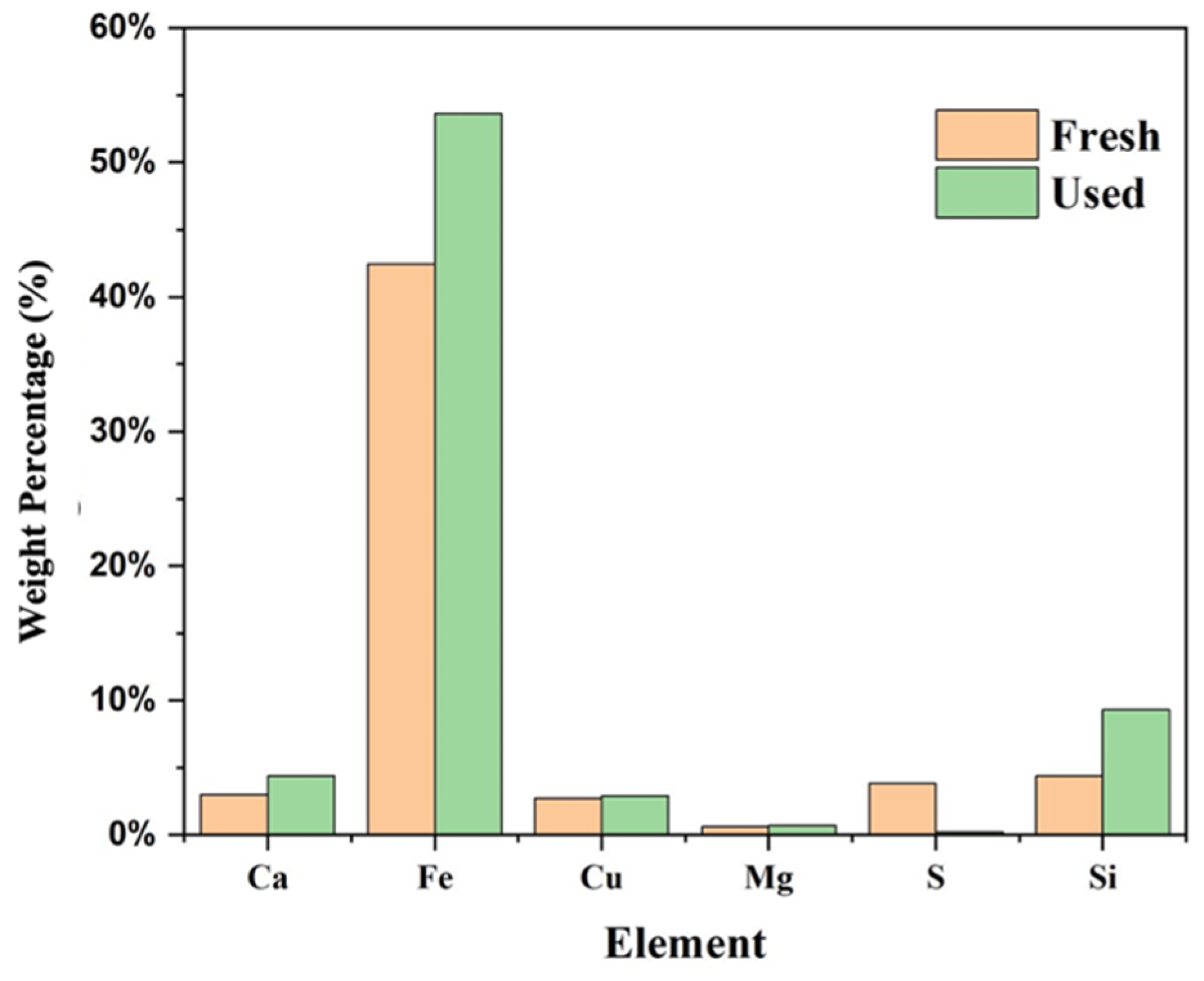
4.5. Evolution of Elements and Morphology
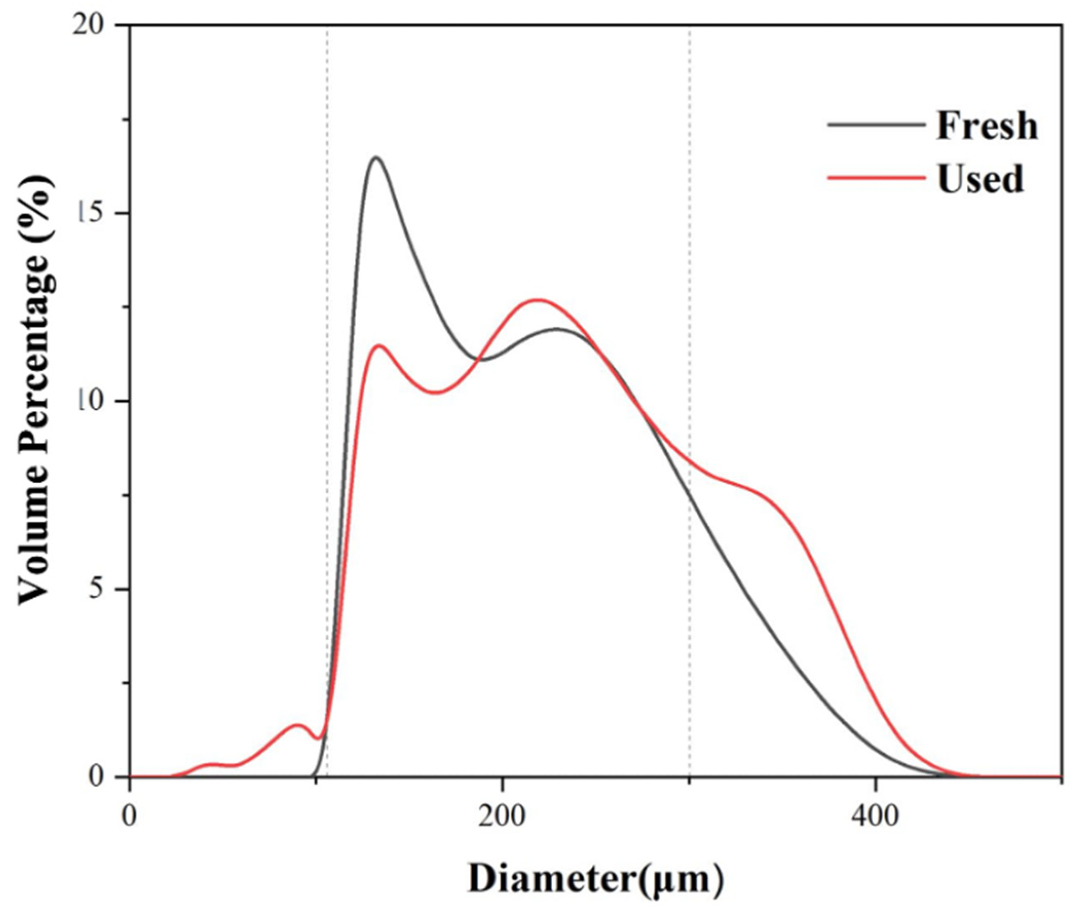
4.6. Particle Size Analysis
5. Conclusions
Author Contributions
Funding
Institutional Review Board Statement
Informed Consent Statement
Data Availability Statement
Conflicts of Interest
References
- Lyngfelt, A.; Leckner, B.; Mattisson, T. A fluidized-bed combustion process with inherent CO2 separation; application of chemical-looping combustion. Chem. Eng. Sci. 2001, 56, 3101–3113. [Google Scholar] [CrossRef]
- Adánez, J.; Abad, A.; García-Labiano, F.; Gayán, P.; Diego, L.F.D. Progress in Chemical-Looping Combustion and Reforming technologies. Prog. Energy Combust. Sci. 2012, 38, 215–282. [Google Scholar] [CrossRef] [Green Version]
- Adánez, J.; de Diego, L.F.; García-Labiano, F.; Gayán, P.; Abad, A.; Palacios, J.M. Selection of Oxygen Carriers for Chemical-Looping Combustion. Energy Fuels 2004, 18, 371–377. [Google Scholar] [CrossRef]
- Lyngfelt, A.; Leckner, B. A 1000 MWth boiler for chemical-looping combustion of solid fuels—Discussion of design and costs. Appl. Energy 2015, 157, 475–487. [Google Scholar] [CrossRef] [Green Version]
- Lyngfelt, A. Chemical-looping combustion of solid fuels—Status of development. Appl. Energy 2014, 113, 1869–1873. [Google Scholar] [CrossRef] [Green Version]
- Mattisson, T.; Keller, M.; Linderholm, C.; Moldenhauer, P.; Rydén, M.; Leion, H.; Lyngfelt, A. Chemical-looping technologies using circulating fluidized bed systems: Status of development. Fuel Process. Technol. 2018, 172, 1–12. [Google Scholar] [CrossRef] [Green Version]
- Adánez, J.; Abad, A.; Mendiara, T.; Gayán, P.; de Diego, L.F.; García-Labiano, F. Chemical looping combustion of solid fuels. Prog. Energy Combust. Sci. 2018, 65, 6–66. [Google Scholar] [CrossRef]
- Matzen, M.; Pinkerton, J.; Wang, X.; Demirel, Y. Use of natural ores as oxygen carriers in chemical looping combustion: A review. Int. J. Greenh. Gas Control. 2017, 65, 1–14. [Google Scholar] [CrossRef] [Green Version]
- Mendiara, T.; Pérez, R.; Abad, A.; de Diego, L.F.; García-Labiano, F.; Gayán, P.; Adánez, J. Low-Cost Fe-Based Oxygen Carrier Materials for the iG-CLC Process with Coal. 1. Ind. Eng. Chem. Res. 2012, 51, 16216–16229. [Google Scholar] [CrossRef]
- Wang, Y.; Tian, X.; Zhao, H.; Liu, K. The use of a low-cost oxygen carrier prepared from red mud and copper ore for in situ gasification chemical looping combustion of coal. Fuel Process. Technol. 2020, 205, 106460. [Google Scholar] [CrossRef]
- Song, T.; Shen, L. Review of reactor for chemical looping combustion of solid fuels. Int. J. Greenh. Gas Control. 2018, 76, 92–110. [Google Scholar] [CrossRef]
- Lyngfelt, A. Chemical Looping Combustion: Status and Development Challenges. Energy Fuels 2020, 34, 9077–9093. [Google Scholar] [CrossRef]
- Mei, D.; Soleimanisalim, A.H.; Linderholm, C.; Lyngfelt, A.; Mattisson, T. Reactivity and lifetime assessment of an oxygen releasable manganese ore with biomass fuels in a 10 kWth pilot rig for chemical looping combustion. Fuel Process. Technol. 2021, 215, 106743. [Google Scholar] [CrossRef]
- Zhao, H.; Wang, K.; Fang, Y.; Ma, J.; Mei, D.; Zheng, C. Characterization of natural copper ore as oxygen carrier in chemical-looping with oxygen uncoupling of anthracite. Int. J. Greenh. Gas Control. 2014, 22, 154–164. [Google Scholar] [CrossRef]
- Mattisson, T.; Lyngfelt, A.; Leion, H. Chemical-looping with oxygen uncoupling for combustion of solid fuels. Int. J. Greenh. Gas Control. 2009, 3, 11–19. [Google Scholar] [CrossRef]
- Mei, D.; Abad, A.; Zhao, H.; Adánez, J. Characterization of a sol–gel derived CuO/CuAl2O4 oxygen carrier for chemical looping combustion (CLC) of gaseous fuels: Relevance of gas–solid and oxygen uncoupling reactions. Fuel Process. Technol. 2015, 133, 210–219. [Google Scholar] [CrossRef] [Green Version]
- Adánez-Rubio, I.; Arjmand, M.; Leion, H.; Gayán, P.; Abad, A.; Mattisson, T.; Lyngfelt, A. Investigation of Combined Supports for Cu-Based Oxygen Carriers for Chemical-Looping with Oxygen Uncoupling (CLOU). Energy Fuels 2013, 27, 3918–3927. [Google Scholar] [CrossRef]
- Jiang, S.; Shen, L.; Wu, J.; Yan, J.; Song, T. The investigations of hematite-CuO oxygen carrier in chemical looping combustion. Chem. Eng. J. 2017, 317, 132–142. [Google Scholar] [CrossRef]
- Zhao, H.; Tian, X.; Ma, J.; Su, M.; Wang, B.; Mei, D. Development of tailor-made oxygen carriers and reactors for chemical looping processes at Huazhong University of Science & Technology. Int. J. Greenh. Gas Control. 2020, 93, 102898. [Google Scholar]
- Ismail, T.M.; Ding, L.; Ramzy, K.; Abd-El-Salam, M. Numerical and experimental analysis for simulating fuel reactor in chemical looping combustor system. Int. J. Coal Sci. Technol. 2020, 7, 551–559. [Google Scholar] [CrossRef]
- Yang, W.; Zhao, H.; Wang, K.; Zheng, C. Synergistic effects of mixtures of iron ores and copper ores as oxygen carriers in chemical-looping combustion. Proc. Combust. Inst. 2015, 35, 2811–2818. [Google Scholar] [CrossRef]
- Mendiara, T.; Adánez-Rubio, I.; Gayán, P.; Abad, A.; de Diego, L.F.; García-Labiano, F.; Adánez, J. Process Comparison for Biomass Combustion: In Situ Gasification-Chemical Looping Combustion (iG-CLC) versus Chemical Looping with Oxygen Uncoupling (CLOU). Energy Technol. 2016, 4, 1130–1136. [Google Scholar] [CrossRef]
- Bao, J.; Li, Z.; Cai, N. Promoting the Reduction Reactivity of Ilmenite by Introducing Foreign Ions in Chemical Looping Combustion. Ind. Eng. Chem. Res. 2013, 52, 6119–6128. [Google Scholar] [CrossRef]
- Siriwardane, R.; Tian, H.; Miller, D.; Richards, G. Fluidized bed testing of commercially prepared MgO-promoted hematite and CuO-Fe2O3 mixed metal oxide oxygen carriers for methane and coal chemical looping combustion. Appl. Energy 2015, 157, 348. [Google Scholar] [CrossRef]
- Tian, X.; Zhao, H.; Ma, J. Cement bonded fine hematite and copper ore particles as oxygen carrier in chemical looping combustion. Appl. Energy 2017, 204, 242–253. [Google Scholar] [CrossRef]
- Wang, Y.; Tian, X.; Zhao, H.; Liu, K.; Dong, Y.; Su, Z.; Zheng, C. Synergetic effects of cement bonded copper ore and red mud as oxygen carrier during in-situ gasification chemical looping combustion of coal char. Fuel 2021, 303, 121295. [Google Scholar] [CrossRef]
- Dong, Y.; Wang, Y.; Ma, J.; Bu, H.; Zheng, C.; Zhao, H. Binary-ore oxygen carriers prepared by extrusion—Spheronization method for chemical looping combustion of coal. Fuel Process. Technol. 2021, 221, 106921. [Google Scholar] [CrossRef]
- Zheng, T.; Li, M.; Mei, D.; Ma, J.; Wang, B.; Xu, Z. Effect of H2S presence on chemical looping reforming (CLR) of biogas with a firebrick supported NiO oxygen carrier. Fuel Process. Technol. 2022, 226, 107088. [Google Scholar] [CrossRef]
- World Health Organization. S.3.6. Bulk Density and Tapped Density of Powders, Final Text for Addition to The International Pharmacopoeia; World Health Organization: Geneva, Switzerland, 2012. [Google Scholar]
- Ma, J.; Zhao, H.; Tian, X.; Wei, Y.; Rajendran, S.; Zhang, Y.; Bhattacharya, S.; Zheng, C. Chemical looping combustion of coal in a 5 kWth interconnected fluidized bed reactor using hematite as oxygen carrier. Appl. Energy 2015, 157, 304–313. [Google Scholar] [CrossRef]
- Cabello, A.; Gayán, P.; García-Labiano, F.; de Diego, L.F.; Abad, A.; Adánez, J. On the attrition evaluation of oxygen carriers in Chemical Looping Combustion. Fuel Process. Technol. 2016, 148, 188–197. [Google Scholar] [CrossRef]
- Purnomo, V.; Yilmaz, D.; Leion, H.; Mattisson, T. Study of defluidization of iron-and manganese-based oxygen carriers under highly reducing conditions in a lab-scale fluidized-bed batch reactor. Fuel Process. Technol. 2021, 219, 106874. [Google Scholar] [CrossRef]
- Mei, D.; Abad, A.; Zhao, H.; Yan, S.; Wang, B.; Yuan, Q. Extension and evaluation of a macroscopic model for syngas-fueled chemical looping combustion. Chem. Eng. Process. 2018, 133, 106–116. [Google Scholar] [CrossRef]
- Mei, D.; Soleimanisalim, A.H.; Lyngfelt, A.; Leion, H.; Linderholm, C.; Mattisson, T. Modelling of gas conversion with an analytical reactor model for biomass chemical looping combustion (bio-CLC) of solid fuels. Chem. Eng. J. 2022, 433, 133563. [Google Scholar] [CrossRef]


| Name | Type | Main XRD Phase |
|---|---|---|
| Magnetite | Fe-ore | Fe3O4 |
| Chalcopyrite | Cu-ore | CuFeS2, FeS2, Cu4Fe5S8 |
| Category and Type | Main XRD Phase | |
|---|---|---|
| Portland | PO32.5R | Ca2SiO4, Ca3SiO5 |
| PO42.5 | Ca3SiO5, SiO2 | |
| PO52.5 | Ca3SiO5, SiO2 | |
| Aluminate | CA50-A600 | CaAl2O4, Ca2Al2SiO7, CaAl4O7 |
| CA50-A700 | CaAl2O4, Ca2Al2SiO7, CaAl4O7 | |
| CA50-A900 | CaAl2O4, Ca2Al2SiO7, CaAl4O7 | |
| CA70 | CaAl4O7, CaAl2O4 | |
| CA80 | Al2O3, CaAl2O4, CaAl4O7 | |
| Sulfoaluminate | SA42.5 | Ca2SiO4, CaSO4, Ca4Al6SO16 |
| XRD Phase | Fe2O3, CuO, |
| Ca2Al2SiO7, CaSO4 | |
| Fe2O3, CuO (wt.%) | 42, 2.73 |
| Roc (wt.%) | 23 |
| Particle size (μm) | 106–300 |
| Bulk density (g/cm3) | 1.65 |
| Crushing strength (N) | 2.27 |
| Dry Time (Day) | 0.5 | 1 | 2 | 3 | 4 | 5 | |
|---|---|---|---|---|---|---|---|
| Cement Type | |||||||
| Cutting strength (N) | PO32.5R | 654.2 | 691.2 | 349.1 | 762.6 | >980 | 235 |
| CA70 | >980 | >980 | >980 | >980 | >980 | >980 | |
| SA42.5 | 355.8 | 405.7 | 157.6 | 460 | 153.3 | 128.2 | |
| Crushing strength (N) | PO32.5R | >980 | >980 | >424.7 | >980 | >980 | >980 |
| CA70 | >980 | >980 | >980 | >980 | >980 | >980 | |
| SA42.5 | 696.7 | 713 | >980 | 791 | 364.7 | 396.8 |
Publisher’s Note: MDPI stays neutral with regard to jurisdictional claims in published maps and institutional affiliations. |
© 2022 by the authors. Licensee MDPI, Basel, Switzerland. This article is an open access article distributed under the terms and conditions of the Creative Commons Attribution (CC BY) license (https://creativecommons.org/licenses/by/4.0/).
Share and Cite
Li, M.; Zheng, T.; Mei, D.; Wang, B.; Ma, J. Selecting and Testing of Cement-Bonded Magnetite and Chalcopyrite as Oxygen Carrier for Chemical-Looping Combustion. Energies 2022, 15, 5093. https://doi.org/10.3390/en15145093
Li M, Zheng T, Mei D, Wang B, Ma J. Selecting and Testing of Cement-Bonded Magnetite and Chalcopyrite as Oxygen Carrier for Chemical-Looping Combustion. Energies. 2022; 15(14):5093. https://doi.org/10.3390/en15145093
Chicago/Turabian StyleLi, Mengjun, Teng Zheng, Daofeng Mei, Baowen Wang, and Jingjing Ma. 2022. "Selecting and Testing of Cement-Bonded Magnetite and Chalcopyrite as Oxygen Carrier for Chemical-Looping Combustion" Energies 15, no. 14: 5093. https://doi.org/10.3390/en15145093
APA StyleLi, M., Zheng, T., Mei, D., Wang, B., & Ma, J. (2022). Selecting and Testing of Cement-Bonded Magnetite and Chalcopyrite as Oxygen Carrier for Chemical-Looping Combustion. Energies, 15(14), 5093. https://doi.org/10.3390/en15145093