Article

A Novel Electronic Wedge Brake Based on Active Disturbance Rejection Control

1
Department of Electrical and Computer Engineering, Inha University Graduate School, Incheon 22212, Korea
2
Department of Mechanical Engineering, Inha University Graduate School, Incheon 22212, Korea
*
Authors to whom correspondence should be addressed.
Energies 2022, 15(14), 5096; https://doi.org/10.3390/en15145096
Submission received: 2 June 2022 / Revised: 9 July 2022 / Accepted: 11 July 2022 / Published: 12 July 2022

Abstract

:
The electronic wedge brake system (EWB) used in the automotive industry is a new structure designed for brake-by-wire systems. This paper proposes a novel EWB system which is mainly composed of a screw-driven wedged inner brake pad, a fixed outer brake pad, a fixed caliper-flexible brake rotor and a hybrid stepper motor. The proposed EWB system does not have a planetary gear set or a ball screw mechanism, it simplified the existing EWB systems. The proposed EWB system is designed to take advantage of the self-interlocking ability of the screw mechanism to hold the brakes with zero-overhauling and the self-energizing ability of the wedge brake pad to reduce the braking effort. In the braking phase, the screw driven wedge inner brake pad forces the flexible rotor against a fixed flat brake pad. The rotor is elastically deformed to make the contact against the fixed pad. Except for the applied force, the friction force between the brake rotor and the wedge pad exerts additional force as the wedge is pulled along the direction of rotation, thus requiring a lower brake actuation force. In this paper, the active disturbance rejection control (ADRC) algorithm is introduced to improve the response ability and stability of the proposed EWB. Simulations are performed to demonstrate the effectiveness of the ADRC controller in the proposed EWB system.

1. Introduction

From traditional fuel vehicles to new energy vehicles, automotive safety has always been a field worth investing time in. The brake system plays a critical role in the maintenance of vehicle driving safety. However, conventional hydraulic braking systems had a negative effect on the environment. Recently, with increased electronic integration, brake-by-wire (BBW) technology has become an alternative to hydraulic brakes since it is greener, safer, and smarter. The BBW system is widely applied in hybrid or electric vehicles since 1998. The BBW systems are composed of electro-hydraulic brake (EHB), electro-mechanical brake (EMB), and electronic wedge brake (EWB). The EHB can be regarded as a transitional product, both EMB and EWB are driven by motors, and the difference between the last two is the force amplification structure. A gear mechanism or planetary gears and a ball-screw mechanism are used in EMB [1], and a wedge-shaped self-amplifying mechanism is applied in the EWB. The EWB is usually simpler and more compact than the EMB in terms of mechanism. Therefore, the specific objective of this study was to design and control an EWB system.
In the early years, the German Aerospace Center firstly developed an EWB prototype-eBrake® [2,3,4,5,6], which is based on two motors to provide the driving force with high self-reinforcement capability, it significantly reduced energy consumption of the brake actuator compared to the EMB system. However, two motors inside the actuator of EWB result in the complexity of the EWB system. A new EWB [7] based on a single motor was developed, this EWB system has advantages over the EWB system with two motors in terms of price, weight, control strategy, and also the car equipped with this single motor EWB system will dramatically improve driver safety. A cross-wedge without any rollers in the EWB system was proposed [8], which is designed to work with a 12 V vehicle battery, this EWB system can easily realize the function of the even distribution of braking force due to the cross-wedge mechanism. An upper-wedge moving EWB prototype [9] with an adaptive proportional-integral (PI) controller was studied, it was found that this EWB system provided a satisfied performance without any jamming the wedge. A new control algorithm based on the position control and the current control of the EWB [10] used on the rear wheel was proposed. A sliding mode controller was applied to the EWB model [11,12] to improve its performance. In the recent study [13], the electromagnetic-mechanical wedge brake system (EMWB) was designed and optimized with multi-objective function at different constraint conditions. The EWB system [14] based on the PID controller is modeled as a 5th order linear system and is a single input and single out (SISO) plant.
Conventional hydraulic braking systems have complex and heavy mechanical mechanisms, and they transfer pressure from the control mechanism to the braking mechanism using brake fluid. The brake shoes may be broken if the brake fluid leaks out, and the brake fluid leakage is potentially harmful to the environment. EMB systems and EWB systems do not contain brake fluids, so there is no risk of brake fluid leakage. In summary, hydraulic brakes are less environmentally friendly than EMB and EWB systems. The diagnostic capability of the conventional braking systems is weak, and it has harder adaptation for assistance systems, with harder assembly and maintenance. Given the above disadvantages, the BBW system was invented. However, a planetary gear set or a ball screw mechanism was usually used in the existing BBW system. In this paper, a simple structure EWB system was proposed to overcome it and has easier adaptation for chassis. The assembly and maintenance of the proposed EWB system are also easy, and it has less weight and is more environmentally friendly. The current design difficulties of the proposed EWB system are as follows: The first one is that to remove a planetary gear set or a ball screw mechanism which can help reduce the weight and save space, a simple mechanism for transforming rotation motion into translation motion should be used as an alternative. A powered screw was considered to play this role. The second one is that using a mechanical amplifier to save energy, eBrake® applied two motors to provide enough braking force. With the help of the self-energizing ability of the wedge brake pad, only one motor is needed in the proposed EWB system to provide enough braking torque. The third one is selecting the appropriate braking motor. It is suggested that stepper motors are the best choice when selecting high torque applications [15], so a stepper motor is selected as the braking motor in this paper. The fourth one is thinking about how to manage the air gap between the brake rotor and brake pads. Some studies mentioned using some complex algorithms to calculate the air gap [11]. However, a small limit switch can successfully manage the air gap in a simple, cheap, and reliable way. Finally, a good robust controller with fast response capability should be designed for the proposed EWB system. The theory of ADRC is extended from the classical PID controller, which incorporates the results of modern control theory and enriches the basic ideas of the PID controller. The basic idea of the PID controller is based on the error and then eliminates the error, however, the main disadvantages of the PID controller are:
  • The selected input error value is unreasonable and will cause the system to overshoot or oscillate;
  • PID controller cannot really solve the contradiction between fast and overshoot;
  • The introduction of differential part is easy to cause system instability.
The ADRC controller compensates for the above problems of the classic PID controller and it inherits the error-driven nature of proportional-integral-derivative (PID), rather than model-based [16,17]. However, the tuning method of the original ADRC was complicated until Gao [18] proposed a simple tuning method. The motivation for utilizing the ADRC method is that the ADRC controller with good robustness and fewer parameters needs to be tuned.
The main contributions of this paper are as follows:
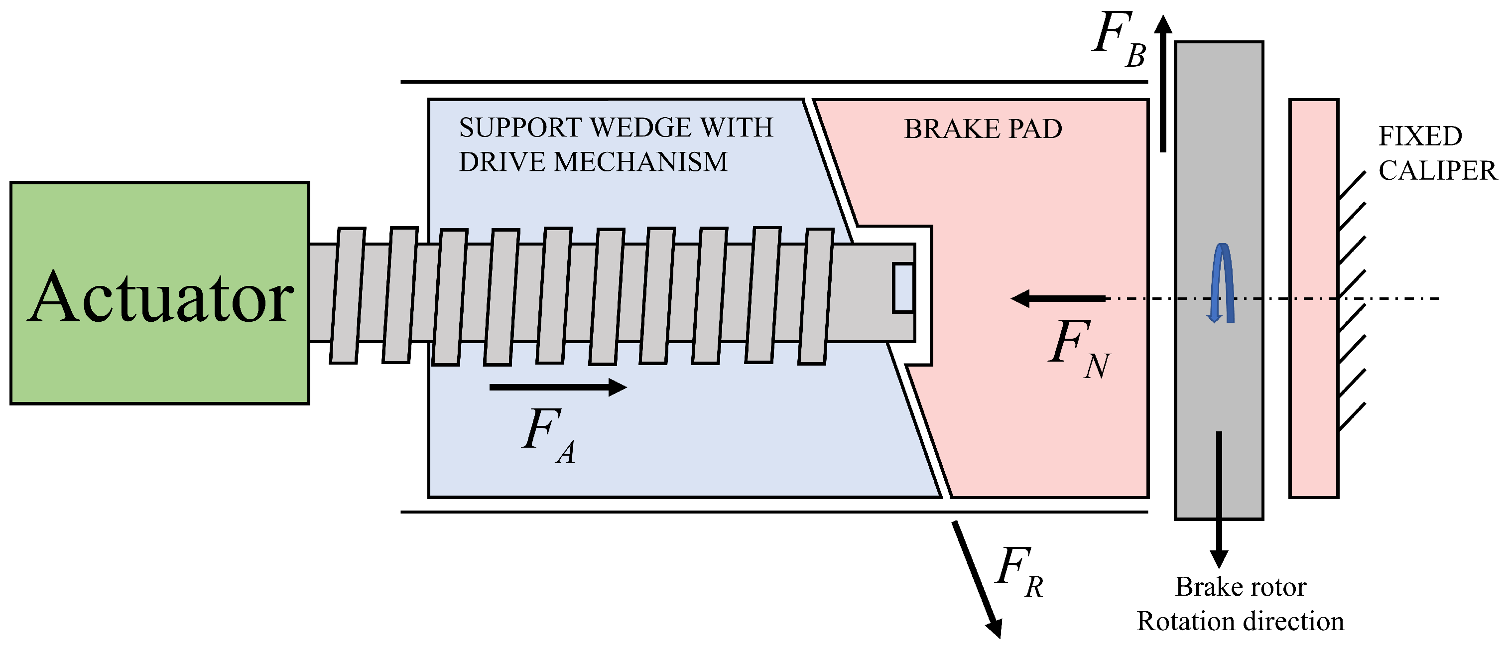
  • Designed a novel simple EWB system without a planetary gear set or a ball screw mechanism. Only a screw, a wedge shape brake pad and a wedge plunger are needed. This effectively simplifies the complex mechanical structures;
  • Introduced active disturbance rejection control (ADRC) into the proposed EWB model, which greatly increased the anti-interference ability of the proposed EWB system and faster response time;
  • Provided a simple method to manage the air gap between the brake rotor and brake pads.
The rest of this paper is organized as follows. Section 2 presents the mathematical model of the proposed EWB system and its corresponding control algorithm. The simulation results of comparison between the PID algorithm, the sliding mode control (SMC) algorithm and the ADRC algorithm are presented in Section 3. Finally, conclusions are summarized in Section 4.

2. Materials and Methods

Figure 1 shows the EWB system that is investigated in this paper. The proposed EWB system consists of two sets of wedge blocks, a screw drive shaft, and a stepper motor. The working principle of the proposed EWB can be described as: once the driver gives the braking command to a brake control unit (BCU) it will calculate the required braking force, then, the BCU will give the control signal to the motor driver to run the stepper motor. The rotation of the stepper motor shaft is converted into translational motion by applying a screw drive shaft while the translational motion of the wedge plunger will force the inner brake pad to contact the brake rotor. The movement of the pads in pressing the disc will generate clamping force and produce brake torque when the wheel rotates. Two magnets are introduced to avoid jamming. To keep the air gap between the brake rotor and the inner brake pad, a limit switch marked as the end stop switch in Figure 1 is applied. A load cell which is used to measure the clamping force is inserted into the float brake pad mount. The air gap between the outer brake pad and the brake rotor can be regulated by the adjustment screw. In Section 2, the mathematical model of the EWB system that generates the clamping force is identified.

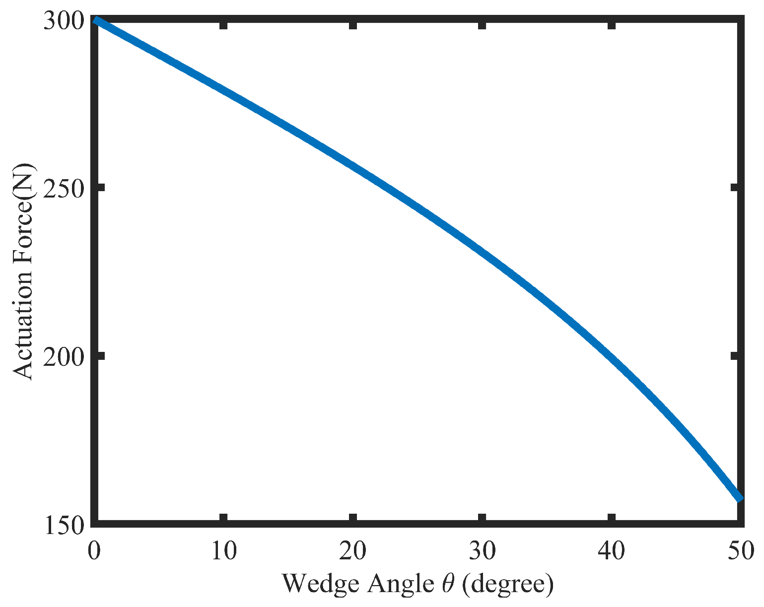
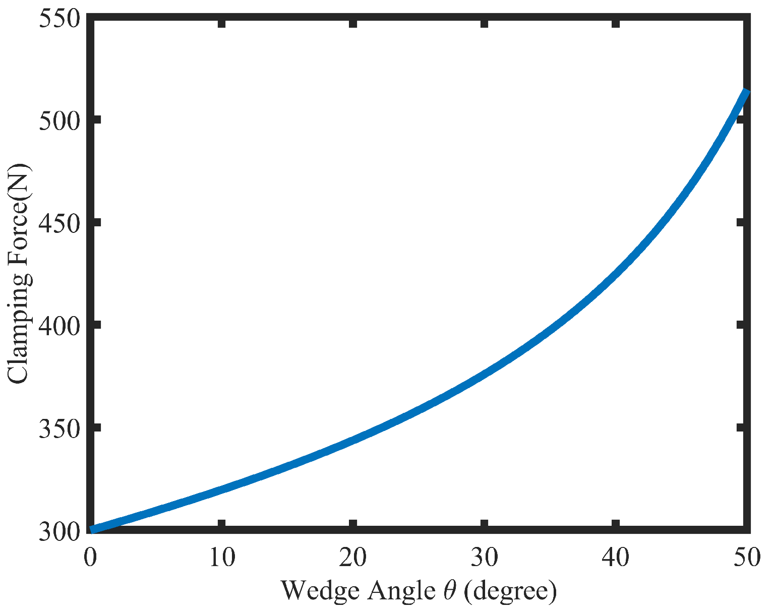
2.1. Wedge Mechanism

The wedge-shape structure is a kind of mechanical amplifier, so it is introduced in the proposed EWB system. The proposed EWB system can be simplified as Figure 2 and the forces acting on the proposed EWB system are marked by arrows as follows.
The relationship between the actuation force and the braking force is described in Equations (1)–(4).
F A + F R sin θ F N = 0
F B F R cos θ = 0
F B = μ F N
F A = F N F R sin θ = F B / μ F R tan θ cos θ = F B / μ F B tan θ = F B ( 1 / μ tan θ )
where μ is the friction coefficient and θ is the wedge angle, F A is the axial actuation force, F B is the friction between the brake pad and the brake rotor, F R is the friction force between the wedges.
The brake torque can be calculated by (5):
T B = F B · R e f f = 1 1 / μ tan θ · F A · R e f f
Figure 3 shows that the relationship between the actuation force and the wedge angle is linear when the wedge angle is below 30 degrees. The relationship between the clamping force and the wedge angle is also linear when the wedge angle is below 30 degrees from Figure 4. Therefore, the wedge angle applied in the proposed EWB should be less than 30 degrees.

2.2. Force Transformation Mechanism

The screw mechanism is applied to transfer the rotation motion of a motor into the translation motion. Figure 5 shows the applied screw and its spread side. The diameter of the screw is denoted by d, and the pitch is denoted by l, the screw lead angle is λ which can be described by (6).
λ H e l i x a n g l e = tan 1 l / π d
The axial displacement of the screw can be written as follows [19]:
x w e d g e = θ m 2 π l
where θ m is the rotation angle of a motor, l is the pitch of the screw.
The velocity of the screw can be calculated by (8).
v w e d g e = l 2 π ω m
where ω m is the speed of a stepper motor.
The clamping force between the pad and the disc can be expressed as (9).
F c l = k · x w e d g e
where k is the caliper stiffness. Since the contact between the screw and the wedge has a much higher stiffness than the caliper structure, the dynamics of the contact can be neglected when the controller is designed.
Because the variance in the wedge velocity is very small, the force acting on the wedge from the screw can be simplified by substituting (3) and (4) into (9).
F A = 1 μ tan θ F N = 1 μ tan θ · k · x w e d g e = 1 μ tan θ · k · l 2 π · θ m
According to the law of conservation of energy, the equivalent load torque can be calculated.
T l = F A · x w e d g e / θ m

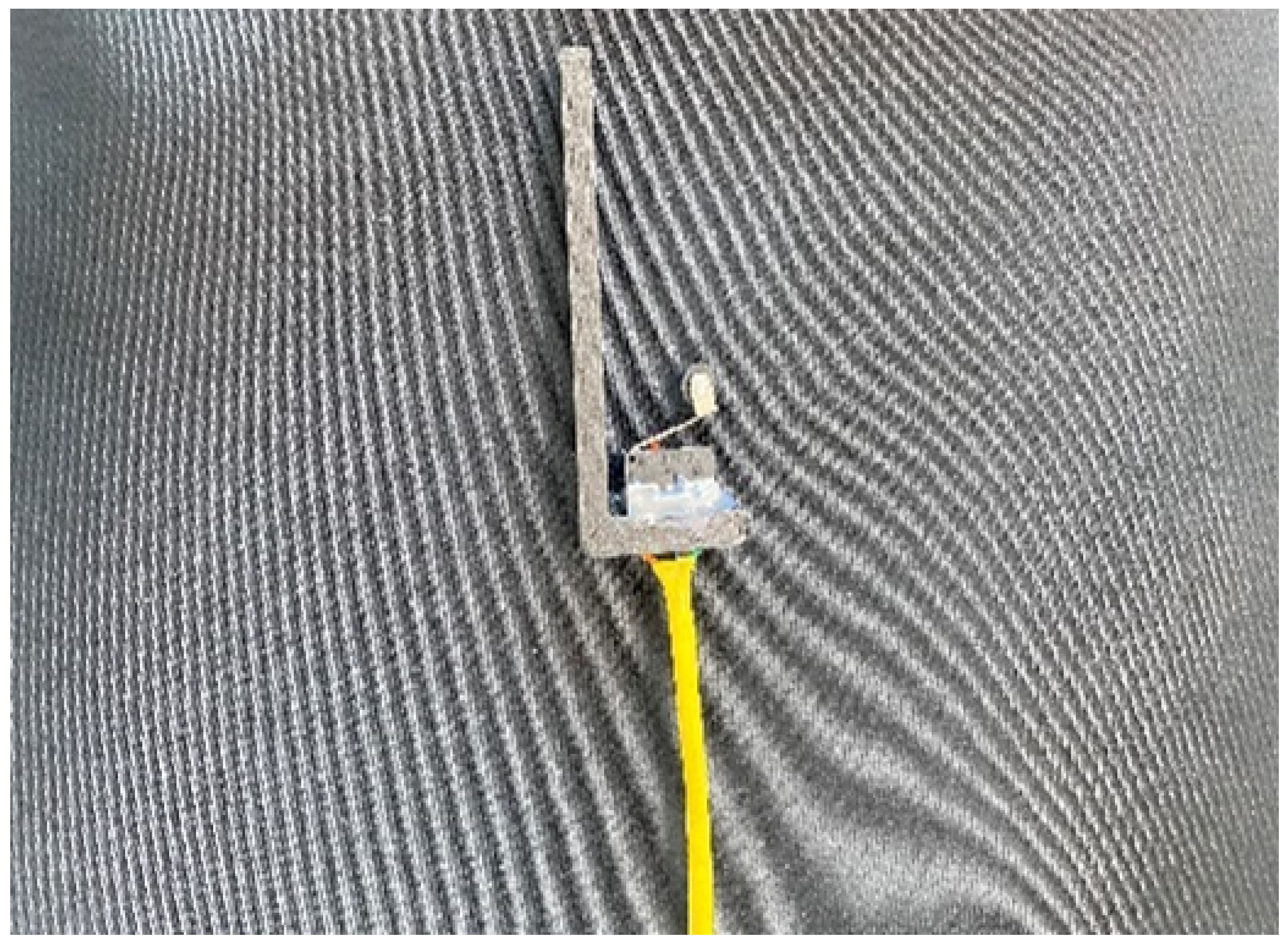
2.3. A Limit Switch and a Hybrid Stepper Motor

The air gap between the pad and the brake rotor is a key parameter in the proposed EWB system, so it should be properly managed after braking otherwise there will be an unwanted residual brake torque. In this study, a small mechanical limit switch attached to the backside of the wedge plunger is used to keep the air gap. The left side of Figure 1 marked End Stop Switch shows the position of the limit switch installation, and its physical photo is shown in Figure 6.
A contact signal is generated when the small pulley on the limit switch is touched and then the stepper motor will stop rotating, which causes the air gap to be precisely controlled.
In the proposed EWB system, the stepper motor is chosen to act as a power source to drive the wedge-shaped brake pad. The hybrid stepper motor can be modeled [20] by using the below standard equations.
u A = R i A + L d i A d t + e A
u B = R i B + L d i B d t + e B
J d ω d t = T e B ω T L
T e = K t i A sin p θ + i B cos p θ
where u A and u B are the phase voltages, i A and i B are the phase currents, R is the phase resistance, L is the phase inductance, e A and e B are the back-EMF voltages, J is the inertia, B is the viscous fiction, ω is the motor speed, θ is the motor position, T e is the electromagnetic torque, K t is the motor torque constant, and T L is the load torque.
The park coordinate transform is applied to switch from the static A B frame to the rotating d q frame. Therefore, the corresponding equations can be written as follows:
u d = R i d + L i d d t + p L i q ω
u q = R i q + L i q d t p L i d ω K t ω
J d ω d t = K t i q B ω T L
where u d and u q are the direct and quadrature voltages, i d and i q are the direct and quadrature currents and p is the number of motor teeth.

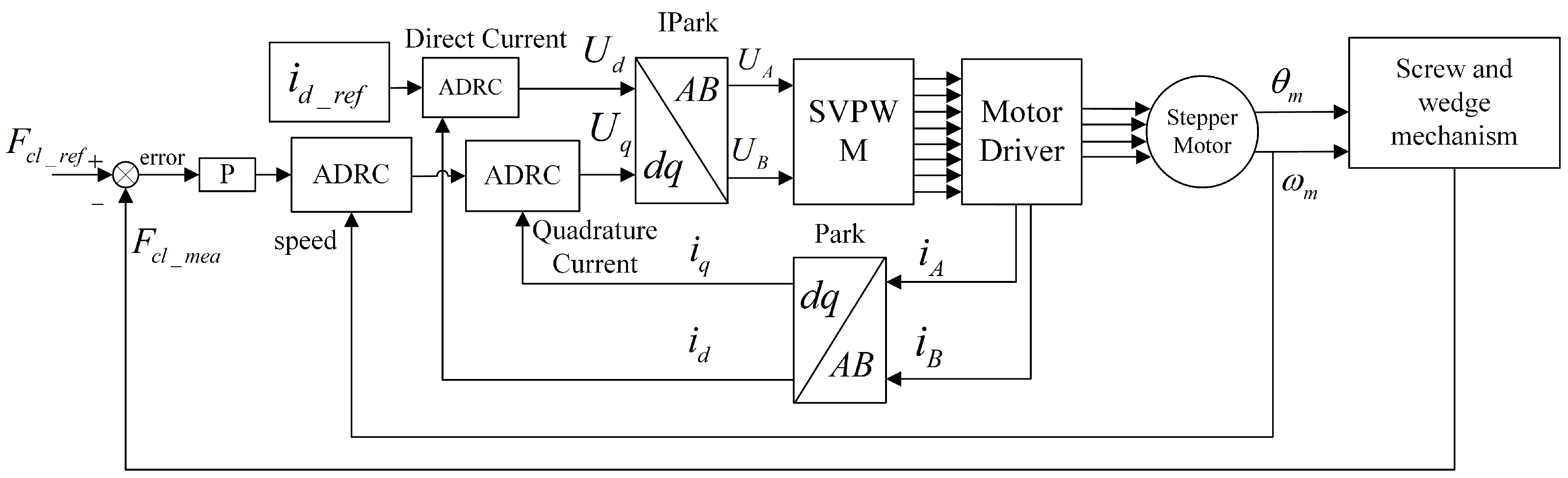
2.4. The Control Algorithm Design of the Proposed EWB System

The control algorithm of the proposed EWB system will be described. The control objective in the proposed EWB system is to drive the clamping force F N to the desired clamping force F N _ d e s . From Equations (7)–(9), the clamping force error can be expressed as the motor position error.
e = F N _ d e s F N = k l 2 π θ m _ d e s θ m
where θ m _ d e s is the desired position of the motor, θ m is the measured position of the motor, k is the caliper stiffness, l is the pitch of the screw.
The problem changes from controlling the clamping force to controlling the rotation angle of the stepper motor. To precisely control the rotation angle of the stepper motor, the ADRC algorithm is introduced in this paper. The ADRC algorithm was originally proposed by Han [21], a typical ADRC algorithm is composed of a tracking differentiator (TD), a nonlinear state error feedback control law (NLSEF) and an extended state observer (ESO). Figure 7 shows the block diagram of n-order ADRC structure.
A generic first-order dynamic system can be described as:
y ˙ = f y , d , t + b u
where y is the output of the system, t is time, b is a constant, u is the control input, d is the unknown external disturbance and f is the total disturbance which is a multivariable function of external disturbance, states and time. Let x 1 = y and x 2 = f , then (20) can be rewritten in the extended state space form of
x ˙ 1 x ˙ 2 = A x 1 x 2 + B u + E h y = x 1 = C x 1 x 2
where A = 0 1 0 0 , B = b 0 , E = 0 1 , and C = 1 0 .
The objective here is to get y to behave as desired by manipulating control input u. As a matter of fact, in the context of feedback control, f ( y , d , t ) is something to be overcome by the control input u, and it is referred to as a “total disturbance”. As a result, we have turned a traditional system identification problem into a disturbance rejection problem, and the implications are vast. The first-order ADRC system should apply a second-order linear extend state observer (LESO). The inputs of LESO are the system output y and the control input u, and the outputs of the LESO are the estimated value of the system output y noted z 1 and the estimated value of total disturbance f noted z 2 .
Assuming the estimated value of f ^ is very closed to f, then we can construct a control input u = f ^ + u 0 b to cancel the total disturbance f and substitute it into (20). Equation (20) can be rewritten as follows.
y ˙ = f ( y , d , t ) + b · f ^ + u 0 b = f f ^ + u 0 u 0
where f ^ is the estimated value of the total disturbance f and u 0 is a function of the tracking error, i.e., a P controller. Therefore, the control problem becomes a matter of estimating and rejecting the total disturbance, which greatly simplifies the problem.
u 0 = k p ( r z 1 )
where r is the desired value, z 1 is the output of the LESO.
The gain k p can be chosen as below [18]
k p = ω c 2
where ω c is the bandwidth of the closed loop.
The equations of the LESO:
z ˙ = A z + B u + l y y ^ y ^ = C z
where A = 0 1 0 0 , B = b 0 , C = 1 0 , and l = l 1 l 2 T . The parameters l 1 and l 2 can be calculated by the characteristic polynomial of the system matrix A [18]:
λ E A = λ + ω o 2 λ + l 1 1 l 2 λ = λ + l 1 λ + l 2 = λ 2 + 2 λ ω o + ω o 2
where ω o is the bandwidth of the LESO, so l 1 = 2 ω o , l 2 = ω o 2 .
The ESO is designed to observe the internal disturbance of the model and give feedforward compensation to the model. The structure of first-order ADRC for the proposed EWB system is shown in Figure 8.
The error between the reference signal r r e f and the estimated value of state z 1 will be fed into the feedback control law(LSEF). The output u 0 of the LSEF is added to the estimated value of state z 2 and then multiplied by a constant to obtain the output of the ADRC.
The control block diagram of the proposed EWB system is shown in Figure 9. For the current loop control part, Equation (16) and (17) can be rewritten in the following way:
i ˙ q = R L i q + p i d ω + K t L ω + 1 L u q = f c ( i q ) + w 1 ( t ) + b c u q = f 1 + b c u q i ˙ d = R L i d p i q + 1 L u d = f c ( i d ) + w 2 ( t ) + b c u d = f 2 + b c u d
where f c ( i k ) = R L i k , (k = d , q ); w 1 t = p i d ω + K t L ω , w 2 t = p i q , b c = 1 L . Here, the sum of f c ( i q ) plus w 1 can be viewed as one generalized disturbance f 1 , another generalized disturbance f 2 is the sum of f c ( i d ) and w 2 , u d and u q as the input of the system.
The equations of current in the q axis can be written in state-space form according to (27).
x ˙ 1 = x 2 + b c u x ˙ 2 = f ˙ 1 = h
where x 1 = i q , x 2 = f 1 and h = f ˙ 1 as unknown disturbance. Same situation for the current in the d axis. The state variable x 1 and x 2 need be known, therefore, the ESO is designed to estimate the state variable x 1 and x 2 .
Equation (28) can be rewritten in the extended state-space form:
x ˙ 1 x ˙ 2 = A x 1 x 2 + B u + E h y = C [ x 1 x 2 ]
where
A = 0 1 0 0 , B = b c 0 , C = 1 0 , E = 0 1
According to (29) and referring to [22], LESO can be constructed in the following form.
z ˙ 1 z ˙ 2 = A z 1 z 2 + b u + L ( y y ^ ) y ^ = C z 1 z 2
where L = l 1 l 2 T is the observer gain vector, which can be obtained using any known method such as the pole placement technique, z 1 z 2 T is the estimated value of the state variable x 1 x 2 T , u is the input, y is the value of real output and y is the estimated value of output.
To simplify the observer tuning process, the observer gain can be parameterized as
L = l 1 l 2 = 2 ω o ω o 2 T
where the observer bandwidth ω o is the only parameter needed to be tuned. Taking q-axis current as an example, with the state observer properly designed, the observer state z 2 can closely track x 2 = f 1 , therefore, a controller can be designed as follows.
u = u 0 z 2 b c
Substituting (32) into (27), ignoring the estimation error in z 2 , the plant is reduced to a unit gain integrator,
i ˙ q = f 1 z 2 + u 0 u 0
which can be easily controlled by a proportional controller, the same principle is applied to the d-axis current.
The proportional controller can be expressed as
u 0 = k p r z 1
where r is a reference signal, z 1 is the observer state from the LESO, k p is a scale factor which is a function of the closed current loop bandwidth, it can be expressed as:
k p = 2 π f c l _ c u r r e n t
where f c l _ c u r r e n t is the current closed loop bandwidth determined by the motor driver.
The relationship [18] between the observer bandwidth ω o and the controller bandwidth ω c is :
ω o 3 5 ω c
It is chosen ω o = 3 ω c in the current loop control part of the proposed EWB system, then (31) can be rewritten as:
L = [ l 1 l 2 ] = 12 π f c l _ c u r r e n t 36 π 2 f 2 c l _ c u r r e n t
The similar procedure for speed loop control part was performed as current loop control part, Equation (18) can be rewritten as:
ω ˙ = K t J i q B J ω 1 J T L = b s i q + f 3 ω
In this case, b s = K t J , f 3 ω = B J ω 1 J T . The parameters of the ADRC can be calculated in the same way as the current loop control part, but the only difference lies in the choice of the relationship between the observer bandwidth ω o and the controller bandwidth ω c . Here, it is chosen that ω o = 5 ω c in the speed loop control part.
The last parameter which is the position loop control gain K P remains to be determined. There is no good method to calculate this parameter, however, it can be obtained by trial and error.

3. Results and Discussion

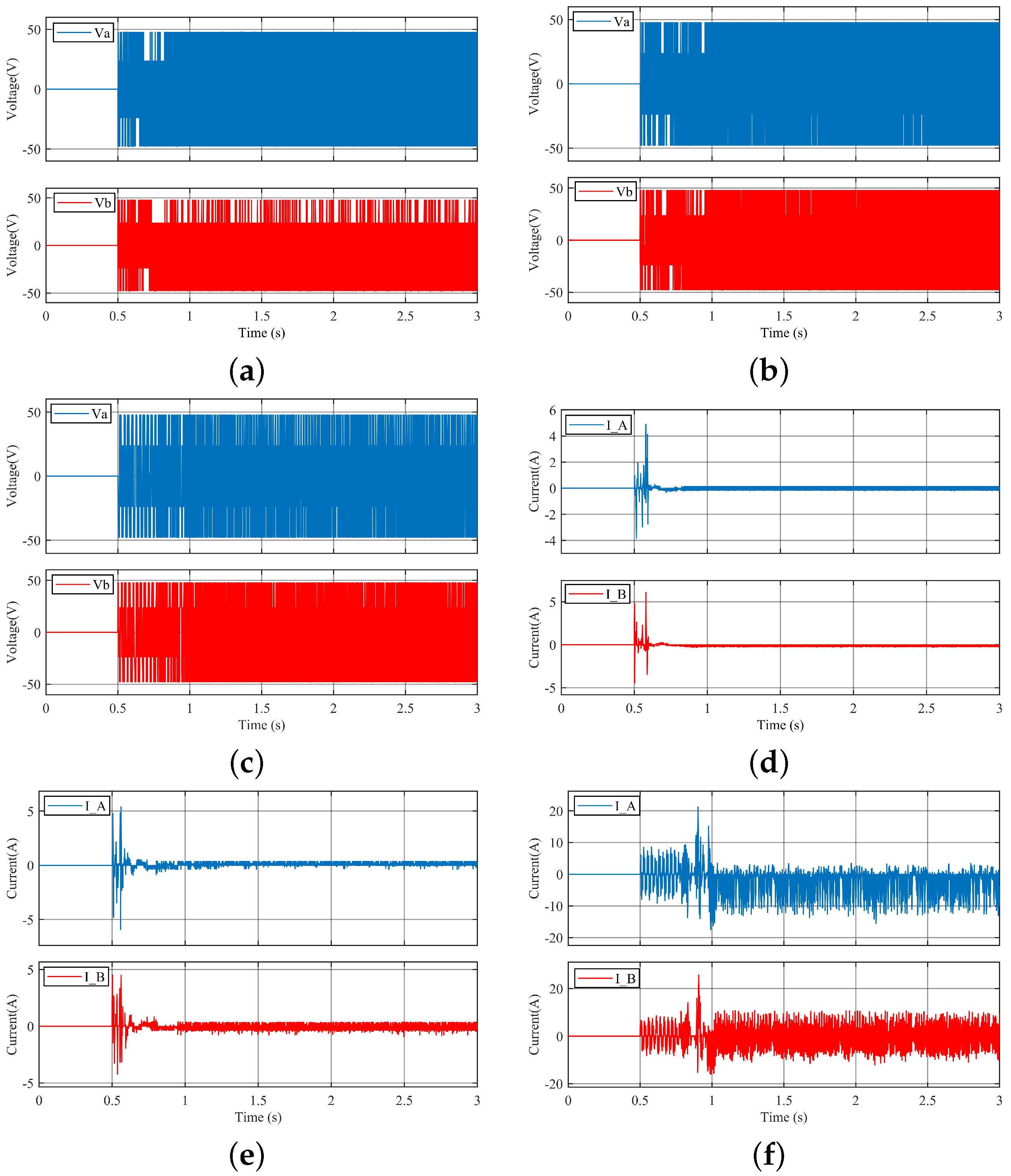
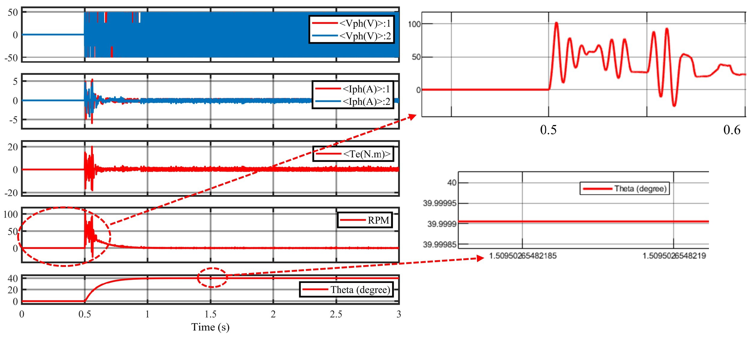
3.1. Step Response of the Proposed EWB System

The proposed EWB model was simulated by Matlab/Simulink. According to (12)–(15), the hybrid stepper motor model was built to simulate the motor behavior. Table 1 lists all parameters of the proposed EWB system.
The classical PID control algorithm and the state-of-the-art sliding mode control (SMC) [23] are introduced as comparisons to the ADRC algorithm. A current closed-loop bandwidth should always be 5–10 times larger than a speed closed-loop [24]. In this paper, the current closed-loop bandwidth f c l _ c u r r e n t is 500 Hz and speed closed-loop bandwidth f c l _ s p e e d is 50 Hz. The parameters of PID controllers can be calculated by (39)–(42) based on the regulator optimal tuning method of Siemens. In detail, for the current control part, we can obtain the PI controller’s parameters as follows:
K p = L 2 T s V D = 1.25
K i = K p R L = 69.7917
In terms of the speed control part, the PI controller parameters are as follows:
K p = 5 J 36 T s K t · π 30 = 0.2989
K i = J 108 T s 2 K t · π 30 = 199.2695
For the position control part, the last parameter was obtained by trial and error.
The parameters of the ADRC controller organized in Table 2 can be calculated based on (35)–(37), the parameter k 1 and k 2 are the control gain of the SMC controller, the parameter q 0 and q 1 are related to the switching speed of sliding surface of the SMC controller, all the parameters of the controllers are listed in Table 2.
The reference input is set to maximum clamping force 10,000 N, i.e., the stepper motor will rotate 40 , and the responses of the PID, the SMC, and the ADRC controllers are shown in Figure 10. There are two shakes in the rising process of the PID controller, while the ADRC controller is much smoother. Although the SMC controller has a fast response, it has excessive overshoot and severe chattering which is one of the bad effects of SMC controllers. During 1 to 3 s, both the output of the PID and the ADRC controllers are in steady state, while the SMC controller is in a relatively steady state, with its output floating between 9600 and 10,441 N. The SMC controller has good responsiveness, but its overshoot and fluctuations at steady state prevent it from being used in practice. Compared to the previous two controllers, the SMC controller is not suitable for this proposed EWB system.
The current and voltage saturation is an important part of the EWB plant. Current is saturated at ±20 A, and voltage is set to saturate at ±48 Volts. Figure 11 shows the actuation voltage and current for the step response of different controllers. However, it is noticed in Figure 11a,d that the proposed EWB system with the ADRC controller has no saturation, so there is no need for anti-windup compensation. The performance of the PID, the SMC, and the ADRC controllers are evaluated and summarized in Table 3. It is seen in Table 3 that the performance of the ADRC controller is better than the SMC controller and the PID controller. Both the PID controller and the ADRC controller are designed without overshoot to avoid fast switching of high currents which may cause the motor damage or overheating. It is noticed that the rise time of the ADRC controller is shorter than the PID controller, the PID controller has a steady state error of 0.24° with a relatively long response time of 0.24 s. However, the ADRC controller has a shorter response time with a steady state error of 0.35°. The reason for the larger steady-state error (SSE) with the ADRC controller over the PID controller is that the ADRC controller sacrifices some of its accuracy to improve response time and disturbance rejection ability. It is known that a PID controller tuning process is a time-consuming task. In summary, the ADRC controller is selected for the proposed system.
The performance of the proposed EWB system based on the ADRC controller is compared to the condition of having a limit switch or not. In Figure 12, it is found that the clamping force will be of a negative value during the decline phase. This runs the risk of damaging the screw, so this situation must be avoided in any case. The clamping force will never be a negative value with the limit switch. This is the reason why a limit switch should be applied.
The phase voltage, the phase current, the electromagnetic torque, the speed, and the rotation angle of the stepper motor are shown in Figure 13 and Figure 14. In Figure 13, it is shown that the rotation angle of the motor is 40°, the maximum speed is about 102 rpm, and the motor was reversed during the period of 0.55–0.568 s. In Figure 14, it is seen that the rotation angle of the motor is 39.65°, the maximum speed is about 82 rpm, and the motor was not reversed during the whole process. It is also noted that the motor speed is not very fast in both controllers, because the faster the motor speed is, the less torque is generated. However, the speed of the motor should not be too low, which will reduce the system’s responsiveness, the job of controllers is to find a balance point between fast response and sufficient torque.

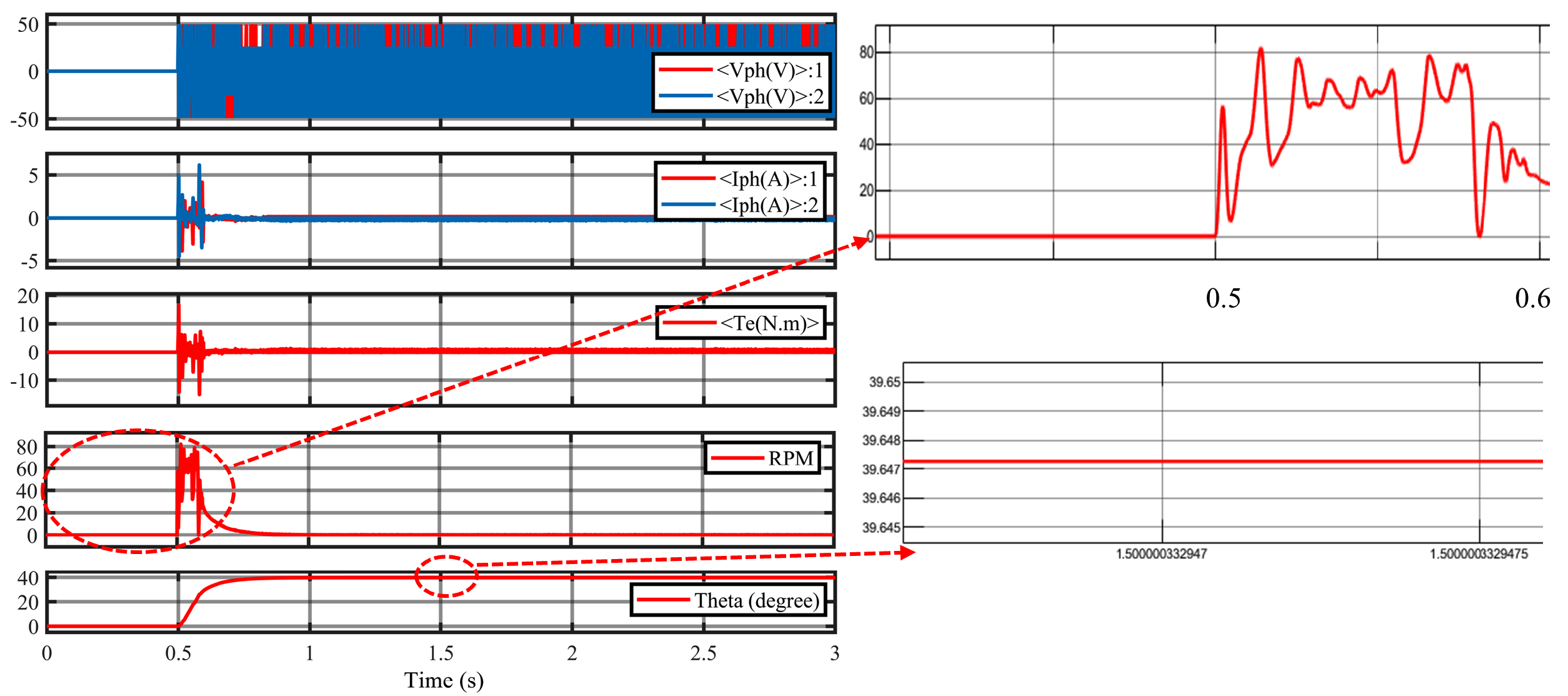
3.2. Simulation for a Vehicle

A regular vehicle modeling with its overall (with passengers) weight was performed to calculate the brake force, velocity and deceleration on an actual vehicle condition. This was performed to obtain the actual response of the vehicle system. The modeling equations of the vehicle wheel to obtain desired outputs are as follows.
A v = r w × a r + a l / 2
V v = r w × ω r + ω l / 2
F v = m v A v
where A v , V v , and F v are linear acceleration, linear velocity and total braking force on vehicle, respectively, r w is the wheel radius, a r , a l are linear acceleration of the right and left wheels, respectively, ω r , ω l are the angular velocity of the right and left wheels, respectively, m v is the mass of the vehicle.
Figure 15 shows the 3-D modeling of the test bench. The flywheel is used as the inertia of the wheel in this study, equations involved in modeling are as follows.
I f = m f r f 2 / 2
θ ¨ f = T d μ f θ ˙ / I f
where m f is the mass of the flywheel, r f is the radius of the flywheel, I f is the inertia of the flywheel, T d is the driving torque, θ ˙ is angular velocity of the flywheel, θ ¨ f is the angular acceleration of the flywheel. Table 4 presents all parameters of the vehicle and the flywheel.
The linear velocity, linear acceleration, and total braking force are shown in Figure 16 when m = 40 kg. Maximum acceleration is about 16.4 rad/s 2 during the braking process. it takes about 7 s to stop from the initial speed of 25 m/s.

4. Conclusions

In this paper, a novel EWB system was developed using the screw actuation to transfer the braking force from the motor through wedged shape brake pads onto the brake rotor. The combined screw-wedge mechanism with self-locking and self-energizing functionality can significantly reduce the consumption of energy. The ADRC control algorithm gives the proposed EWB system the ability to react quickly and disturbance rejection. The results of the simulation showed that the proposed EWB system with the ADRC algorithm has better performance than the PID and the SMC algorithm.
A real test bench that includes a flywheel, a driving motor, a stepper motor, and its driver, and other mechanical parts as shown in Figure 15 will be fabricated to analyze the performance of the proposed EWB system in the next stage of work.

Author Contributions

Conceptualization, F.X. and C.C.; methodology, F.X. and C.C.; software, F.X.; validation, F.X. and C.C.; formal analysis, F.X. and C.C.; investigation, F.X. and C.C.; data curation, F.X.; writing—original draft preparation, F.X.; writing—review and editing, F.X. and C.C.; visualization, F.X.; supervision, C.C.; project administration, C.C.; funding acquisition, C.C. All authors have read and agreed to the published version of the manuscript.

Funding

This research was funded by Inha University.

Institutional Review Board Statement

Not applicable.

Informed Consent Statement

Not applicable.

Data Availability Statement

Not applicable.

Conflicts of Interest

The authors declare no conflict of interest.

References

  1. Schwarz, R.; Isermann, R.; Böhm, J.; Nell, J.; Rieth, P. Modeling and Control of an Electromechanical Disk Brake; Technical Report, SAE Technical Paper; SAE: Warrendale, PA, USA, 1998. [Google Scholar]
  2. Hartmann, H.; Schautt, M.; Pascucci, A.; Gombert, B. eBrake®-the mechatronic wedge brake. In SAE Transactions; SAE: Warrendale, PA, USA, 2002; pp. 2146–2151. [Google Scholar]
  3. Roberts, R.; Schautt, M.; Hartmann, H.; Gombert, B. Modelling and validation of the mechatronic wedge brake. In SAE Transactions; SAE: Warrendale, PA, USA, 2003; pp. 2376–2386. [Google Scholar]
  4. Roberts, R.; Gombert, B.; Hartmann, H.; Lange, D.; Schautt, M. Testing the Mechatronic Wedge Brake; SAE Technical Paper; SAE: Warrendale, PA, USA, 2004; Volume 1, p. 2766. [Google Scholar]
  5. Ho, L.M.; Roberts, R.; Hartmann, H.; Gombert, B. The Electronic Wedge Brake-EWB; Technical Report, SAE Technical Paper; SAE: Warrendale, PA, USA, 2006. [Google Scholar]
  6. Semsey, Á.; Roberts, R. Simulation in the Development of the Electronic Wedge Brake; Technical Report, SAE Technical Paper; SAE: Warrendale, PA, USA, 2006. [Google Scholar]
  7. Fox, J.; Roberts, R.; Baier-Welt, C.; Ho, L.M.; Lacraru, L.; Gombert, B. Modeling and control of a single motor electronic wedge brake. In SAE Transactions; SAE: Warrendale, PA, USA, 2007; pp. 321–331. [Google Scholar]
  8. Kim, J.G.; Kim, M.J.; Kim, J.K.; Noh, K.H. Developing of Electronic Wedge Brake with Cross Wedge; Technical Report, SAE Technical Paper; SAE: Warrendale, PA, USA, 2009. [Google Scholar]
  9. Jo, C.; Lee, S.; Song, H.; Cho, Y.; Kim, I.; Hyun, D.; Kim, H. Design and control of an upper-wedge-type electronic brake. Proc. Inst. Mech. Eng. Part D J. Automob. Eng. 2010, 224, 1393–1405. [Google Scholar] [CrossRef]
  10. Kim, J.G.; Kim, M.; Chun, J.; Huh, K. ABS/ESC/EPB Control of Electronic Wedge Brake; Technical Report, SAE Technical Paper; SAE: Warrendale, PA, USA, 2010. [Google Scholar]
  11. Han, K.; Kim, M.; Huh, K. Modeling and control of an electronic wedge brake. Proc. Inst. Mech. Eng. Part C J. Mech. Eng. Sci. 2012, 226, 2440–2455. [Google Scholar] [CrossRef]
  12. Atia, M.R.; Haggag, S.A.; Kamal, A.M. Enhanced electromechanical brake-by-wire system using sliding mode controller. J. Dyn. Syst. Meas. Control. 2016, 138, 041003. [Google Scholar] [CrossRef]
  13. Yao, M.; Miao, J.; Cao, S.; Chai, H.; Chen, S. The structure design and optimization of electromagnetic-mechanical wedge brake system. IEEE Access 2019, 8, 3996–4004. [Google Scholar] [CrossRef]
  14. Che Hasan, M.H.; Khair Hassan, M.; Ahmad, F.; Marhaban, M.H. Modelling and Design of Optimized Electronic Wedge Brake. In Proceedings of the 2019 IEEE International Conference on Automatic Control and Intelligent Systems (I2CACIS), Selangor, Malaysia, 29 June 2019; pp. 189–193. [Google Scholar] [CrossRef]
  15. Derammelaere, S.; Haemers, M.; De Viaene, J.; Verbelen, F.; Stockman, K. A quantitative comparison between BLDC, PMSM, brushed DC and stepping motor technologies. In Proceedings of the 2016 19th International Conference on Electrical Machines and Systems (ICEMS), Chiba, Japan, 13–16 November 2016; pp. 1–5. [Google Scholar]
  16. Arasteh, E.; Assadian, F. New Robust Control Design of Brake-by-Wire Actuators. In Advanced Applications of Hydrogen and Engineering Systems in the Automotive Industry; IntechOpen: London, UK, 2020. [Google Scholar]
  17. Arasteh, E.; Assadian, F. A Comparative Analysis of Brake-by-Wire Smart Actuators Using Optimization Strategies. Energies 2022, 15, 634. [Google Scholar] [CrossRef]
  18. Gao, Z. Scaling and bandwidth-parameterization based controller tuning. In Proceedings of the Proceedings of the 2006 American Control Conference, Minneapolis, MN, USA, 14–16 June 2006; Volume 6, pp. 4989–4996. [Google Scholar]
  19. Acarnley, P.P. Stepping Motors: A Guide to Theory and Practice; Number 63; IET: London, UK, 2002; pp. 36–39. [Google Scholar]
  20. Butcher, M.; Masi, A.; Picatoste, R.; Giustiniani, A. Hybrid stepper motor electrical model extensions for use in intelligent drives. IEEE Trans. Ind. Electron. 2013, 61, 917–929. [Google Scholar] [CrossRef]
  21. Han, J. From PID to active disturbance rejection control. IEEE Trans. Ind. Electron. 2009, 56, 900–906. [Google Scholar] [CrossRef]
  22. Gao, Z. Active disturbance rejection control: A paradigm shift in feedback control system design. In Proceedings of the 2006 American Control Conference, Minneapolis, MN, USA, 14–16 June 2006; p. 7. [Google Scholar]
  23. Lai, C.K.; Lin, B.W.; Lai, H.Y.; Chen, G.Y. FPGA-based hybrid stepper motor drive system design by variable structure control. Actuators 2021, 10, 113. [Google Scholar] [CrossRef]
  24. Guo, B.; Bacha, S.; Alamir, M. A review on ADRC based PMSM control designs. In Proceedings of the IECON 2017-43rd Annual Conference of the IEEE Industrial Electronics Society, Beijing, China, 29 October–1 November 2017; pp. 1747–1753. [Google Scholar]
Figure 1. Configuration of the proposed EWB system.
Energies 15 05096 g001
Figure 2. The force balance analysis of the proposed EWB system.
Energies 15 05096 g002
Figure 3. The relationship between the actuation force and the wedge angle.
Energies 15 05096 g003
Figure 4. The relationship between the clamping force and the wedge angle.
Energies 15 05096 g004
Figure 5. The screw mechanism.
Energies 15 05096 g005
Figure 6. The physical photo of the limit switch.
Energies 15 05096 g006
Figure 7. N-order ADRC structure.
Energies 15 05096 g007
Figure 8. First order ADRC structure.
Energies 15 05096 g008
Figure 9. Control block diagram of the proposed EWB system.
Energies 15 05096 g009
Figure 10. The clamping force tracking performance at the maximum target value.
Energies 15 05096 g010
Figure 11. The actuation signals for the step response of different controllers. (a) The actuation voltage of the ADRC controller; (b)The actuation voltage of the PID controller; (c) The actuation voltage of the SMC controller; (d) The actuation current of the ADRC controller; (e) The actuation current of the PID controller; (f) The actuation current of the SMC controller.
Energies 15 05096 g011
Figure 12. The performance comparison with or without a limit switch.
Energies 15 05096 g012
Figure 13. The outputs of stepper motor in the EWB system based on the PID controller.
Energies 15 05096 g013
Figure 14. The outputs of stepper motor in the EWB system based on the ADRC controller.
Energies 15 05096 g014
Figure 15. The 3D CAD Model of the test bench.
Energies 15 05096 g015
Figure 16. The time domain curve of linear velocity, linear acceleration, and total braking force.
Energies 15 05096 g016
Table 1. The parameters of the proposed EWB system.
ParameterSymbolValue
Wedge angle θ 22.5
Pitchl2/1000 m
Caliper stiffnessk4.5 × 10 7 N/m
Friction coefficient μ 0.35
Phasesph2
Motor phase resistanceR0.46 Ω
Motor phase inductanceL1.2 × 10 2 H
Motor teeth Z r 50
Rotor inertiaJ3.52 × 10 3   N · m / s 2
Step angle A s t e p 1.8
Torque constant K t 1.7128 N · m / A
Viscous damping coefficientB1 × 10 3 N · m / s
Detent torque T d m 0.0510 N · m
Maximum flux ψ m 0.137 Wb
Switching cycle T s 0.0001 s
Power supply V D 48 V
Table 2. The parameters of the PID, the SMC and the ADRC controllers.
PIDSMCADRC
Current control K p = 1.25 K p = 1.25 K p c = 3141.6
K i = 69.7917 K i = 69.7917 b c = 83.33
l 1 c = 18 , 849.6
l 2 c = 8.88 × 10 7
Speed control K p = 0.2989 k 1 = 0.1
k 2 = 0.1
q 0 = 0.05
q 1 = 0.1
K p s = 314.1593
K i = 199.2695 b s = 486.5909
l 1 s = 3142
l 2 s = 2.47 × 10 6
Position control K p = 0.00599 K p = 0.000846
Table 3. The performance of the PID, the SMC and the ADRC controller.
ControllerPresent of Overshoot (%)Rise Time (s)
PID00.24
SMC83.68∼99.77%0.17
ADRC00.16
ControllerSettling Time (s)Stead State Error (degree)
PID0.330.24
SMC0.14−1.6∼1.76
ADRC0.230.35
Table 4. The parameters of the vehicle and the flywheel.
ParameterSymbolValue
vehicle’s mass m v 6500 kg
wheel radius r w 0.25 m
flywheel’s mass m f 40 kg
flywheel’s radius r f 0.19 m
friction coefficient μ f 0.35
Publisher’s Note: MDPI stays neutral with regard to jurisdictional claims in published maps and institutional affiliations.

