Project Report

A Method of Determining Optimal Parameters for the Secondary Energy Source of a Multisource Hydrostatic Drive System in Machines Working in Closed Spaces

by
Krzysztof Kędzia
Department of Technical Systems Operation and Maintenance, Faculty of Mechanical Engineering, Wroclaw University of Science and Technology, Wyspaińskiego Str. 27, 50-370 Wrocław, Poland
Energies 2022, 15(14), 5132; https://doi.org/10.3390/en15145132
Submission received: 8 June 2022 / Revised: 4 July 2022 / Accepted: 12 July 2022 / Published: 14 July 2022
(This article belongs to the Special Issue Advanced Fluid Power and Mechatronics)

Abstract

:
What benefits, from the point of view of the energy and ecological performance of a multisource drive system, can be gained for a particular control criterion through the use of appropriate secondary energy source parameters (accumulator volume V g and initial gas pressure p g ) for a given work cycle of a machine working in closed spaces? This paper describes a method of determining energy and ecological efficiency for a selected multisource drive system control criterion and presents potential benefits resulting from a proper choice of secondary energy source parameters for a selected control criterion. Using, as an example, a multisource hydrostatic drive system with a combustion engine as the primary energy source, the energy consumption and the ecological parameters (nitrogen oxides N O x emissions, carbon monoxide C O emissions and opacity D Y M ) were analysed for selected work cycles and different hydraulic accumulator parameters, i.e., initial gas pressure ( p g ) and accumulator volume ( V g ). The investigations showed that the optimal parameters for the secondary energy source for energy performance criteria are different from those for the ecological criteria. It can be concluded that when a bank of accumulators is used, it will be possible to select a secondary energy source capacity that is optimal for the given work cycle, thereby improving the energy balance or the ecological balance.

1. Introduction

Today’s machines and equipment market is regulated by rigorous standards concerning energy consumption, environmental pollution, noisiness, safety, ergonomics, recycling and so on [1]. The persons responsible for implementing the provisions and rules contained in the standards are mainly design and construction engineers. The maze of regulations, new and more sophisticated technologies and a larger number of physical phenomena taken into account in machines put greater demands on the design and construction engineers. It is becoming increasingly difficult for them to design a machine or a piece of equipment characterized by even higher efficiency, lower emissions of harmful or hazardous substances, higher performance, higher reliability, greater safety, lower noisiness and greater operating ease without support from an expert in the given field, procedure and expert system in which they are themselves not specialists [2].
Currently, in many research centres worldwide, research is ongoing into increasing the efficiency of the drive systems used in machines operating in repeatable fast-changing duty cycles [3]. The reasons for this are: the possibility of recovering some of the energy dissipated in the process of braking, by collecting and storing it in accumulators and then reusing it in the most energy-intensive phases of the machine’s operation cycle, and increasing the life of the energy source through its stabilization and operation close to the nominal operating parameters. This means that replacing classic drive systems with drive systems incorporating energy accumulation is an interesting and promising method of increasing drive system efficiency by as much as 30%. However, because of the required extensive knowledge, the high degree of complexity of the issues involved and the expenses connected with the design and construction of such drive systems, the relevant research is conducted in only a few specialized research and development centres [2]. This paper supplements and extends the rational basis for the design and construction of multisource drive systems. Using the proposed procedure one can answer, for a given operation cycle and drive system energy optimization criterion, the following questions:
  • Is the expansion of a single-source drive system to a multisource drive system justified for the given drive system?
  • If so, what benefits can be gained from the drive system expansion?
  • What benefits can we obtain from using the appropriate parameters for the secondary energy source (volume V g and initial gas pressure p g ) for a given cycle of operation of a machine operating in closed rooms, from the point of view of energy and environmental efficiency?

2. State of Knowledge

Machine and vehicle drive systems with energy accumulation are one of the elements of eco-friendly technology. In conditions in which machines and vehicles are subject to external cyclically repeatable fast-changing loads, such systems reduce energy consumption and pollution emissions. They also make it possible to effectively shape energy processes through kinetic or potential energy recuperation [2,4,5,6,7,8].
Generally, energy consumption by machine and vehicle drive systems can be reduced through the following measures [2,9]:
  • Increasing the efficiency of drive system components;
  • Appropriately matching the operating areas of the drive system’s highly efficient components;
  • Using a multisource (hybrid) drive system to restrict the primary energy source performance characteristic to the most advantageous areas and to recover some of the kinetic or potential energy that is usually lost.
In order to adopt the above measures in drive system design, knowledge relating to the transformation, transmission, distribution, recuperation and storage of energy is needed, and many additional requirements must be satisfied. This particularly applies to:
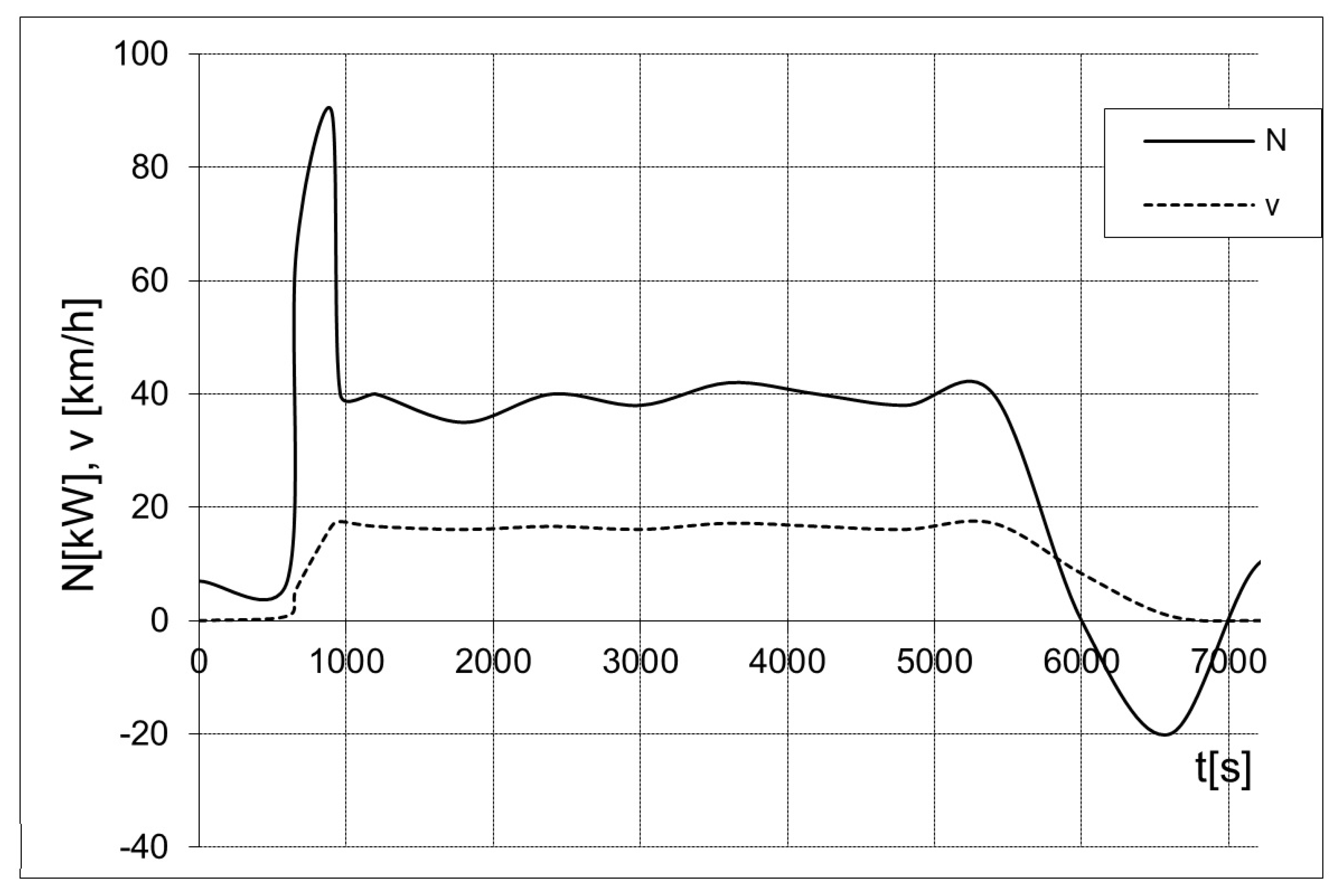
  • Knowledge of the load characteristics constituting the basis for a system energy analysis. The characteristics, comprising intensity variables (linear and angular velocities, flow rates) and strain variables (forces, torques, pressures), can be represented by a duty point, load curves, an operating area, an operation cyclogram or a representative operation cycle. Sometimes a load spectrum (a more general form) is used.
  • Knowledge of the energy characteristics (efficiency or loss of energy) in the whole operating area of every energy transformation, transmission, distribution, recuperation and accumulation component.
  • The possibility of quantitatively assessing the energy efficiency of different drive system variants operating under the same load conditions.
  • The solution of the problems connected with the choice of a structure and components for the drive system.
  • The solution of the problems relating to control, and especially to the synthesis of control systems.
In the literature on the subject, the concept of multisource (hybrid) drives has been known for a few decades [2,4,5,7,8]. However, for economic and technological reasons, there have been periods of high and very low activity in the relevant research and development. These periods have been closely connected with energy crises. Currently a major influential factor is the environmental aspect [2,10].
A structure for an energy efficient drive system should be chosen on the basis of the energy balance of the machine. A measure of energy performance quality is the size of the energy loss in relation to the effective work. The notion of a system includes the types of components, the methods of connecting them and a set of relations occurring among them. The load characteristics of the work-performing system are the basis for creating an energy balance [2,9,11,12,13].
Due to load variation over time, the state of loading should be described by a kinematic operation cycle or a load spectrum. The effect of load variability on the efficiency of a drive system depends on the structure of the latter, and mainly on the distribution of the efficiency of its components in the field of their energy characteristics. The most disadvantageous efficiency distributions (characteristics in the form of isoefficiency curves) characterize combustion engines and transmission gears performing the function of stepless torque converters. Energy transmission systems and simple energy transformation systems (e.g., mechanical gearboxes) have a relatively small effect on the efficiency of the system. In order to minimize energy losses in the combustion engine–energy transformation system set, the problem of the optimization of the choice of components and a control system for this set must be solved [2,12].
Therefore, it can be concluded that energy consumption by work machines can be reduced by adopting the following measures:
  • Increasing the efficiency of the classic drive system through the use of more efficient components and their more advantageous matching;
  • Optimizing the control of energy transformation processes in classic drive systems;
  • Building drive systems with a multisource structure to optimize the machine’s energy balance by stabilizing the operation of the primary energy source and/or recuperating energy.
Multisource systems are potentially most able to reduce energy losses. Due to the complex structure of a multisource system, the high requirements the power transmission and control systems must meet and the associated costs, the choice of a particular multisource system must be based on a comprehensive analysis of the machine’s energy balance. The work system load characteristics supply the initial information for choosing a system structure [2].

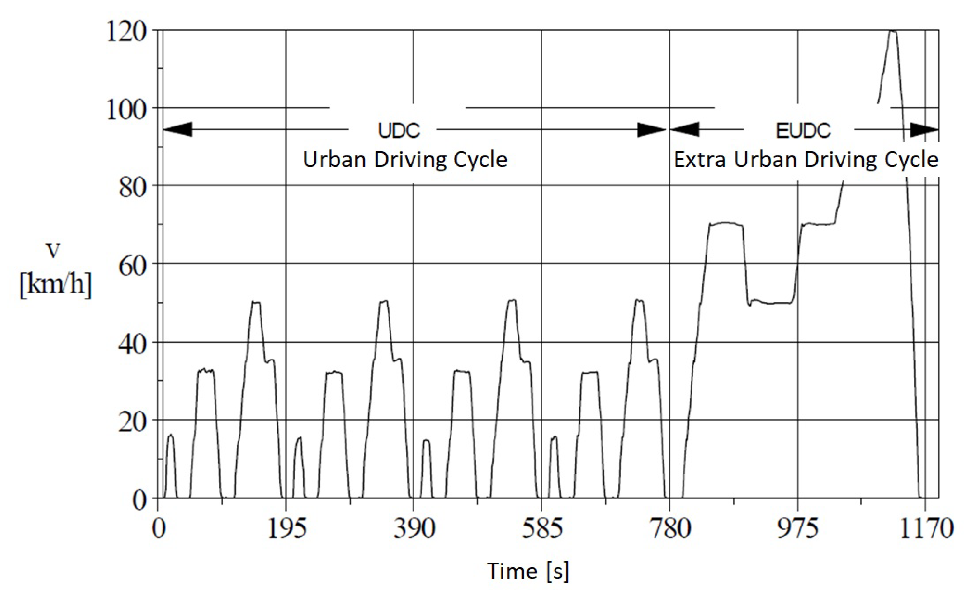
2.1. Machine Operation Cycles

The basis for all analyses of multisource systems it the machine operation cycle stemming mainly from the task for which the machine was built [2,5,7,14,15].
When describing the operation of a machine or a drive system, a velocity measurement is often made, and then on the basis of the energy balance of the work system a force and power cyclogram is produced. Statistical, actual, simple and substitute cycles, etc., in the form of v = f ( t ) are used in the case of vehicles (Figure 1) [2,16,17,18,19,20].
Various driving cycles are used when comparing fuel consumption or toxic substance emissions of vehicles moving in simulated traffic conditions [21]. The synthetic ECE cycle (Figure 2) devised by the Economic Commission for Europe is the one most frequently used in European countries [22].
There are also ways of representing loads in, e.g., a spectral form, a linear form or in the form of an area [21].

2.2. Primary Energy Sources and Stipulations Regarding Characteristics of Primary Energy Sources

The following stipulations express the expectations regarding the characteristics of primary energy sources:
  • M ( ω ) = c o n s t ;
  • ω ( M ) = c o n s t ;
  • M > 0 for 0 ω ω l ;
  • M * ω = c o n s t ;
where M is the torque, ω is the angular velocity and the index l is the limit.
An energy source that would ideally meet all the stipulations does not, of course, exist.
The steam engine is an example of an energy source closest to the ideal. However, in work-machine drives, electric motors and combustion engines are most frequently used as primary energy sources. Primary electric motors predominate mainly in manufacturing machines such as cranes, presses and machine tools, which are usually powered by electricity from the mains. In these cases, the simplest type of electric motor—the squirrel-cage induction motor—is mainly used. Work machines with their own source of energy supply, such as earthmoving machines and most construction machines, are typically equipped with a combustion engine (usually a compression–ignition engine), which performs the role of a primary energy source.

2.3. Secondary Energy Sources—General Characterization

Secondary energy sources (accumulators) in a hybrid drive system should be characterized by [7,25,26]:
  • A high-energy-flow instantaneous power with a high energy efficiency at the source input;
  • The smallest possible internal losses in the secondary energy source during energy storage for a suitably long time;
  • A high-energy-flow instantaneous power with a high energy efficiency at the source output;
  • A high specific power [ kW kg ] ;
  • A high specific energy [ kJ kg ] .
An energy accumulator is usually charged or discharged at a considerable instantaneous power, which is due to sharp changes in the loading of, e.g., the road wheels of a vehicle moving in traffic characterized by frequent stops and starts. Although such power peaks last for a very short time, at a too-low specific power of the accumulator, the above-mentioned energy accumulator efficiency conditions will not be met. Furthermore, the greater the specific power and energy, the lighter the accumulator weight [27].

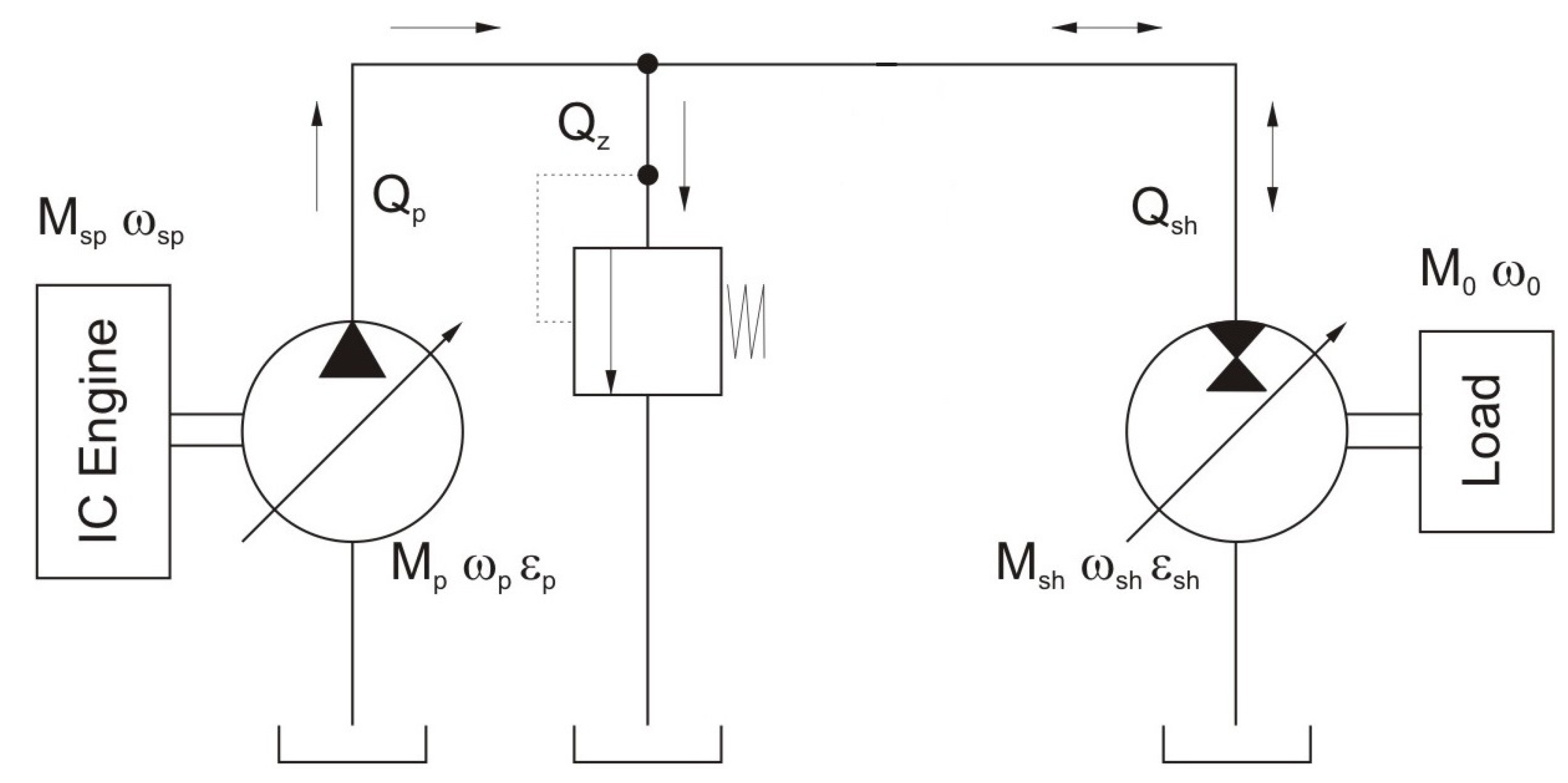
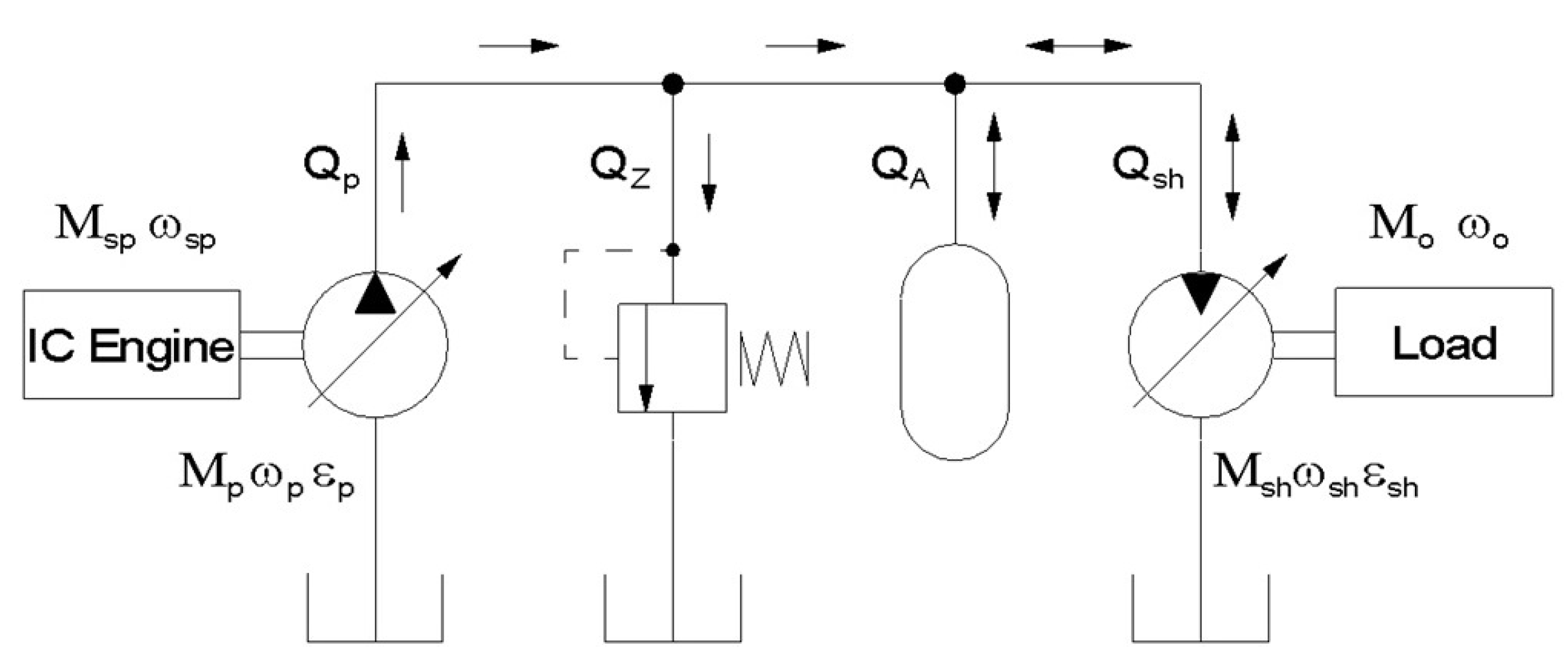
2.4. Hydrostatic Transmission—Exemplary Performer of Energy Transformation and Transmission Functions in Hybrid Drive Systems

Figure 3 shows an exemplary hydrostatic transmission working in an open-loop system. The transmission consists of units varying in their capacity/displacement, controlled by hydraulic amplifiers [28,29]. The energy source is usually a combustion engine or an electric motor.
In order to illustrate the method, it is necessary to use mathematical models of the hydrostatic units. In these models, the engine’s volumetric and hydraulic–mechanical losses are described using the same or similar relations as those used to describe pump losses. Experience indicates that the volumetric losses in an engine are lower than in a pump, owing to the better filling of the engine’s working chambers [2,25,30,31,32,33,34,35,36].
Variable-capacity displacement hydrostatic machines such as multi-plunger axial-flow and radial-flow units and vane units are designed for reversible operation. However, in a hydrostatic machine working as a hydrostatic engine up to a certain thrust runner deflection, the torque losses stemming from the unit’s design exceed the torque obtainable from the conversion of hydraulic energy into mechanical energy. Analyses concerning the variability coefficient ( V C ) take into account self-locking occurring in the hydrostatic engine [2,37,38,39]. More information on the self-locking phenomenon can be found in studies on screw joints and worm gears [40,41,42,43,44].

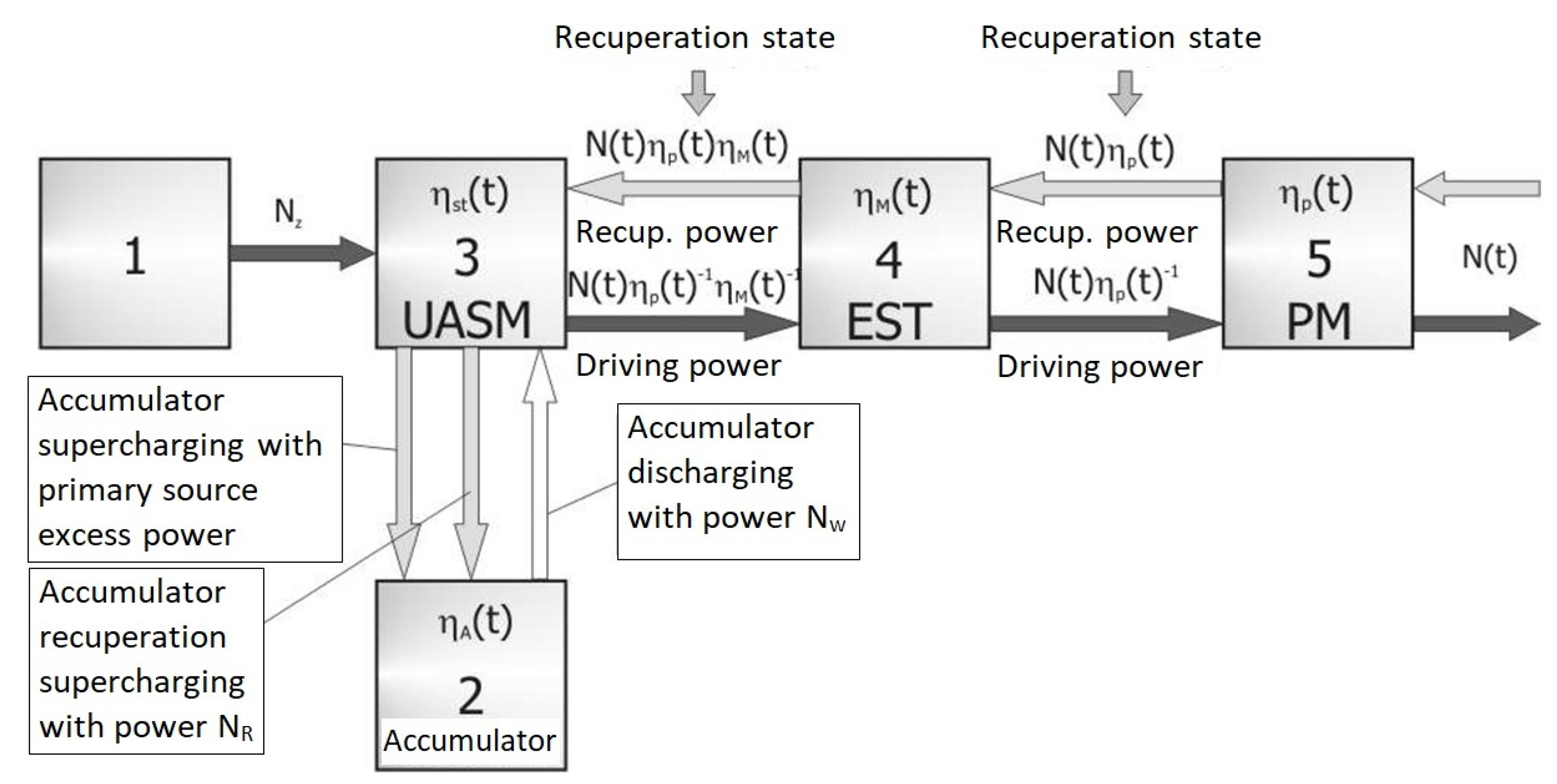
2.5. Determination of Energy Parameters of Primary and Secondary Energy Source

Power takeoff from the primary energy source or harmful substances emissions to the atmosphere during the cycle can be reduced to a minimum through [20,45]:
  • Proper interaction between the primary energy source and the secondary energy source;
  • The choice of a proper operating range for each of the sources;
  • Matching the accumulator’s energy capacity.
In order to determine the optimal parameters of a multisource system, one should use a method that also enables the determination of a proper control for the system. The principal method, among the various methods of determining the energy parameters of a hybrid system, consists in determining the minimal power at the output of the primary energy source and the minimal energy capacity of the accumulator in the drive of any machine, in an arbitrarily complex work cycle [9,11,15,20,46].
The multisource drive system shown schematically in Figure 4 is used as an example to describe the method of determining the parameters of a multisource system. The function N ( t ) defines changes in the road wheel load power over time. The power transmission functions of the individual system blocks are shown and described in Figure 4 [2].

2.6. Control of Multisource Systems

The control of power flow through the individual structures of a multisource drive unit is key for the proper utilization of the energy resources of the primary and secondary sources. In order to perform the set functions, the control system of an energy-efficient drive unit must meet several conditions for reducing the energy-intensiveness of operation of this unit [2,47,48,49,50,51,52,53,54].
An exemplary method, which can be used to determine the control of the multisource hydrostatic drive system shown schematically in Figure 5, is the kinetostatic method (Figure 6) [2,5,55,56,57,58,59].
The kinetostatic method algorithm is used to determine the settings of hydrostatic units (pump: ϵ p ; engine: ϵ s h ), the combustion engine’s duty point ( M s p , ω s p ) and the parameters of the hydraulic accumulator [2,60].

2.7. Drive System Performance Measures

The design and optimization process requires a rating system for comparing individual designs [12,61,62,63,64,65]. A commonly used performance measure is the efficiency, defined as the ratio of useful work (energy, power) to supplied work (energy, power). The efficiency can be determined for each drive system component separately and for the whole drive system or work machine. The efficiency of drive system components is variable and depends on the drive system’s operating parameters. It is difficult to assess the efficiency of complex drive systems due to the interrelations and interactions between the parameters and components of the drive system [2,66,67,68,69,70,71,72]. Other methods of assessing this efficiency are ecological measures of efficiency, which can be assessed through European standards and regulations [70], and other measures concerning noise and vibration (Law Gazette 2005 no. 157 item 1318, PN-EN 458:2006) are applied to, e.g., combustion engines operating in work machines. On the basis of these measures, the average emissions of individual exhaust gas components per engine power unit are determined.
To evaluate the energy performance of the analysed system, the following drive system efficiency formula was used:
η c = 0 t c N o ( M o , ω o ) d t 0 t c g e ( M s p , ω s p ) W o d t ,
where g e is the fuel consumption at the combustion engine’s duty point ( M s p , ω s p ) [ g h ] and W o is the calorific value of the fuel [ kJ dm 3 ] , ( η c : total efficiency; N: power; ω : angular velocity; M: torque; t c : end time of the working cycle; indexes: 0: load; s p : primary source of energy).
Graphs of torque M o and angular velocity ω o over time (Figure 7) were used to describe the system load.

3. Kinetostatic Method of Selecting Work Parameters for Multisource Hydrostatic Drive System

The kinetostatic method was applied to the multisource drive system made up of components with known characteristics, for its load presented in the form of a machine work cycle and for the selected criterion, to determine the following parameters:
  • The optimal duty point of the primary energy source;
  • The initial parameters of the secondary energy source;
  • The control paths for the other components of the drive system.
The above was achieved by assuming that:
  • The primary energy source operated at one duty point throughout the system work cycle;
  • The charge levels of the secondary energy source at the beginning and end of the work cycle were the same.
For the selected criterion, the method yielded a set of parameters for controlling the multisource drive system [2,17,73,74,75,76,77,78,79].

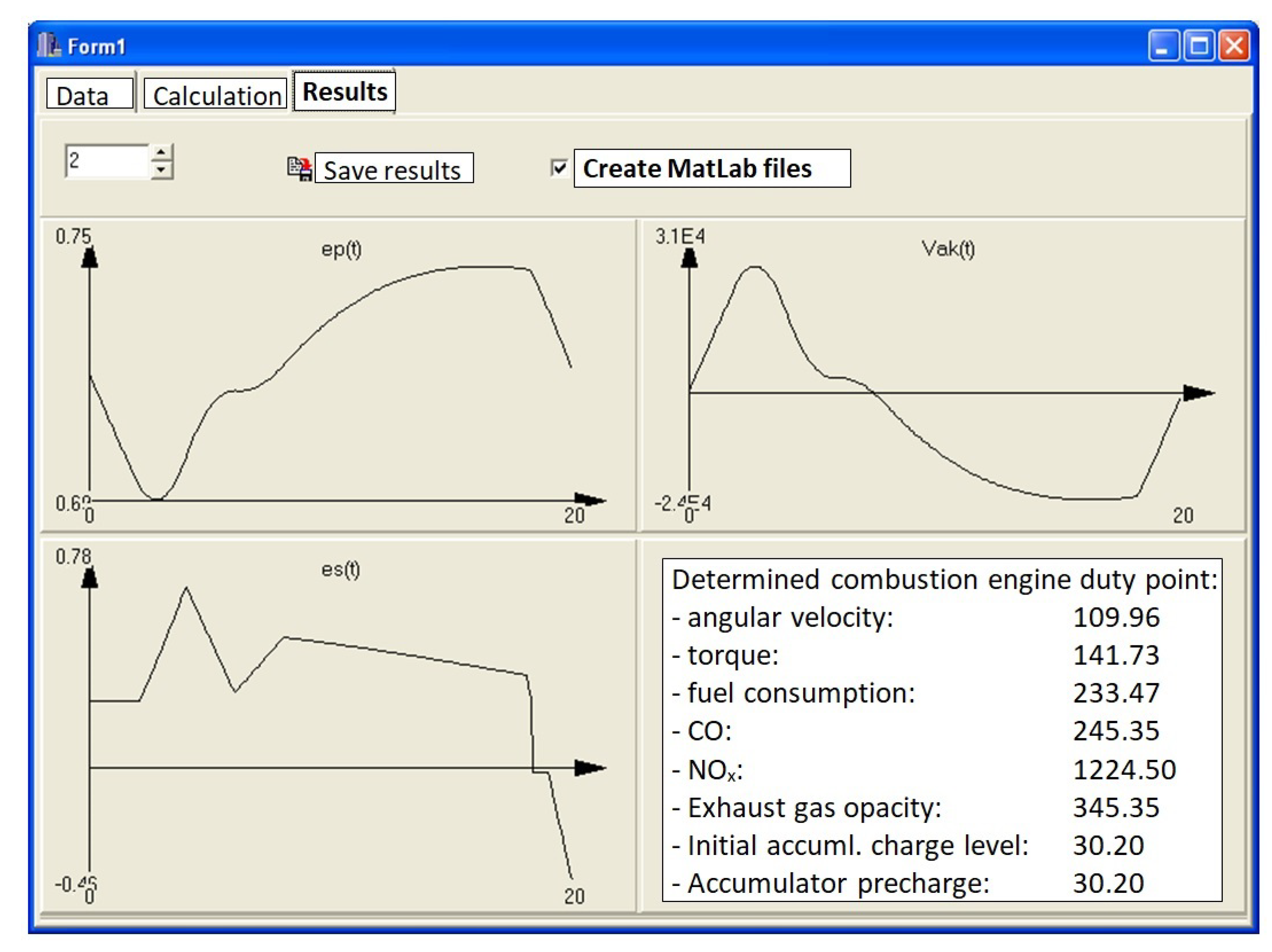
3.1. Computer Program for Determining Operating Parameters of Multisource Hydrostatic Drive System

A computer program based on the kinetostatic method refined by the author was written in C++ to determine the operating parameters of a drive system with a gas hydraulic accumulator. The program can be directly applied to any multisource drive system with a gas hydraulic accumulator connected directly to a hydraulic system (without using an energy converter) [2].

3.1.1. Input Data and Results

The input quantities for calculating the operating parameters of a hybrid hydrostatic drive systems were:
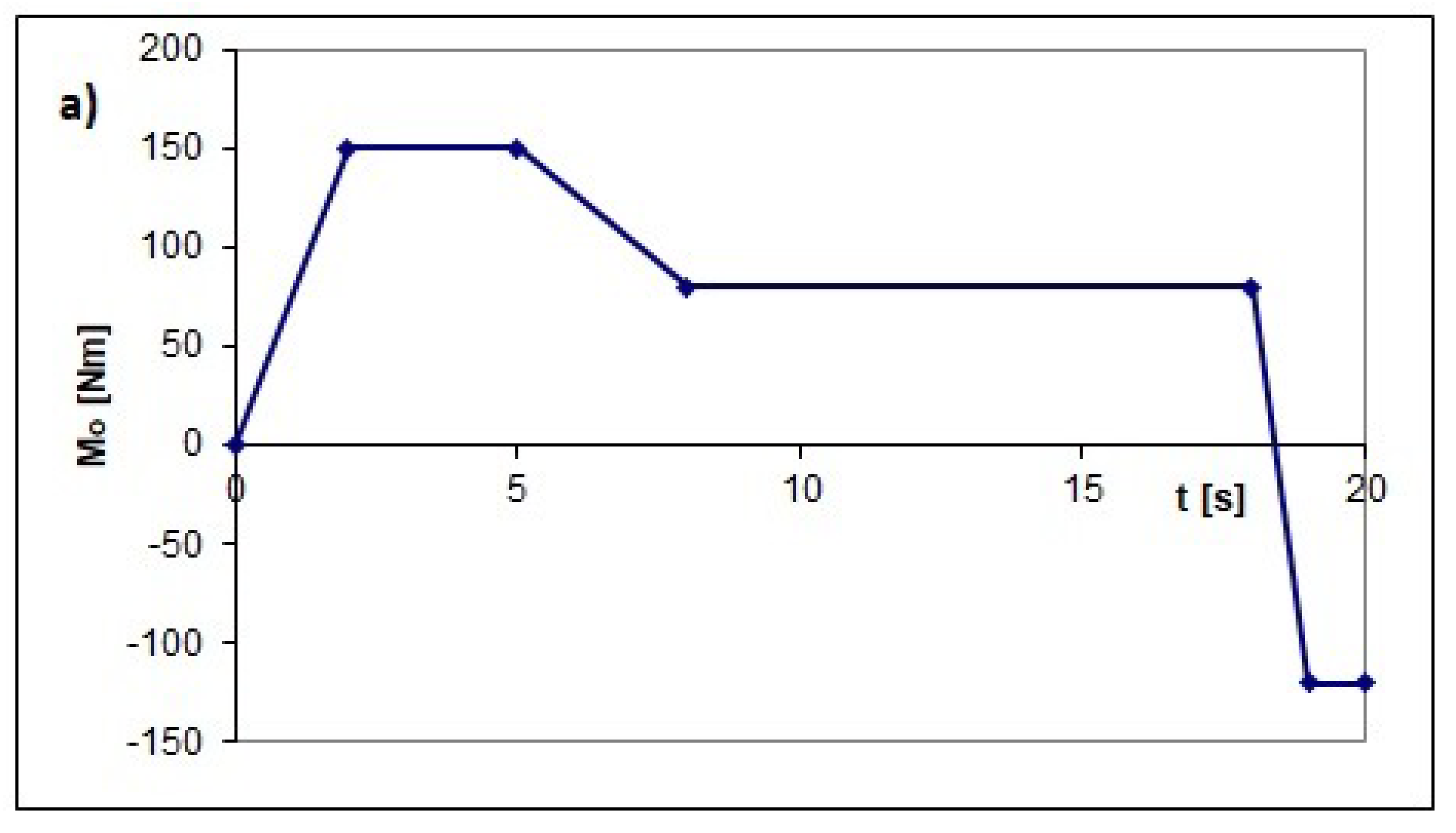
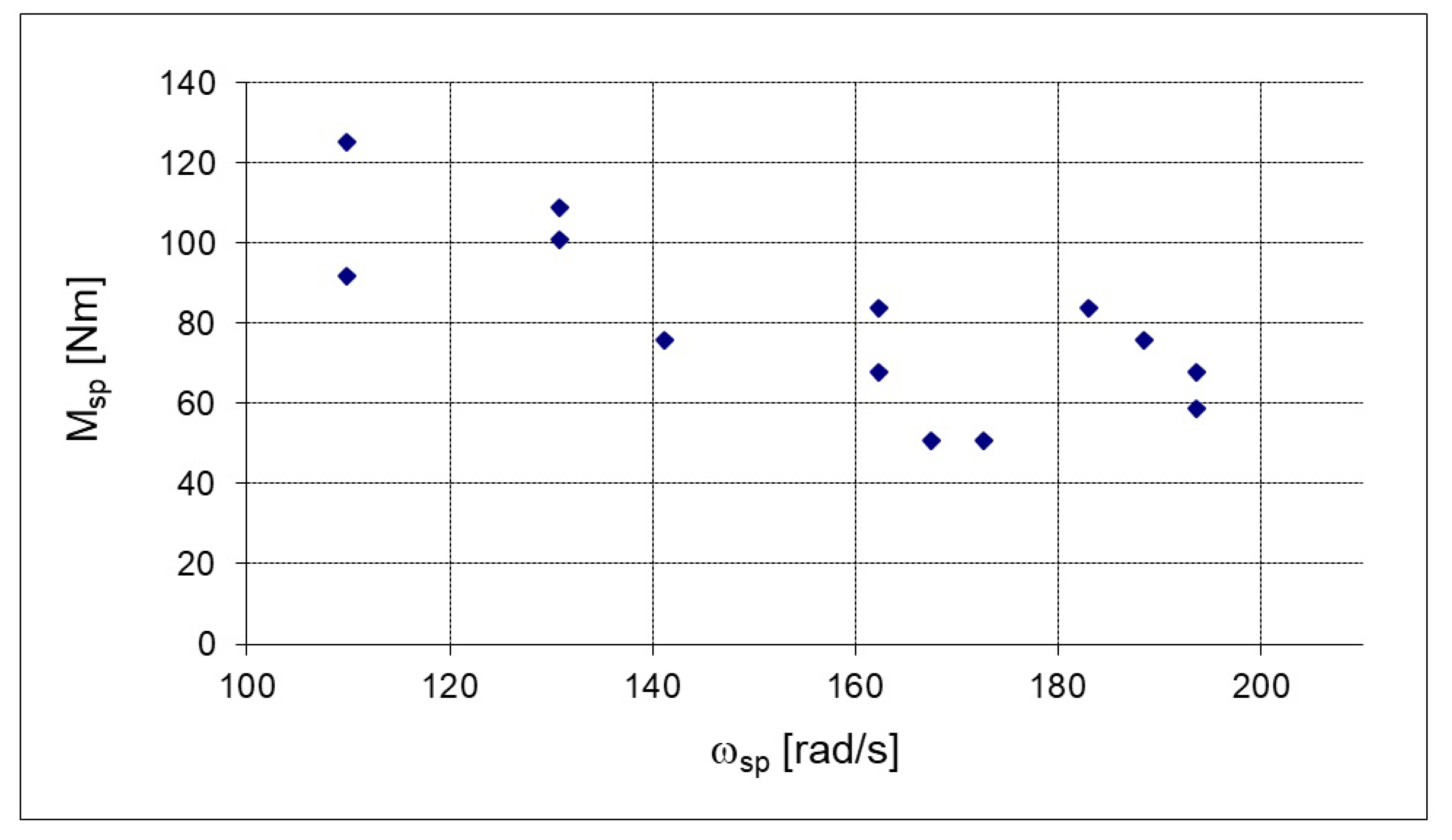
  • Load characteristics in the form of cyclograms of:
    • Angular velocity ω o [ rad s ] ;
    • Torque in the form of BRUTTO M o [Nm].
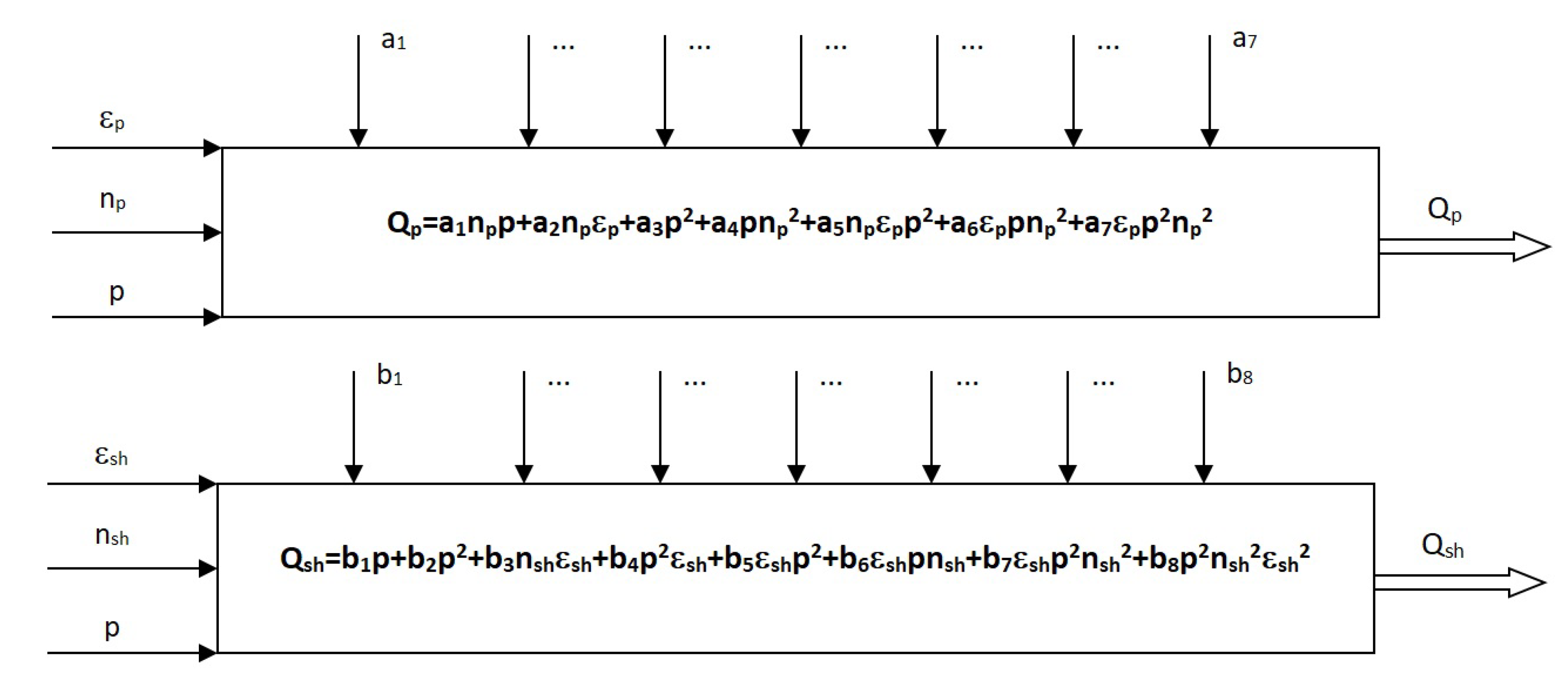
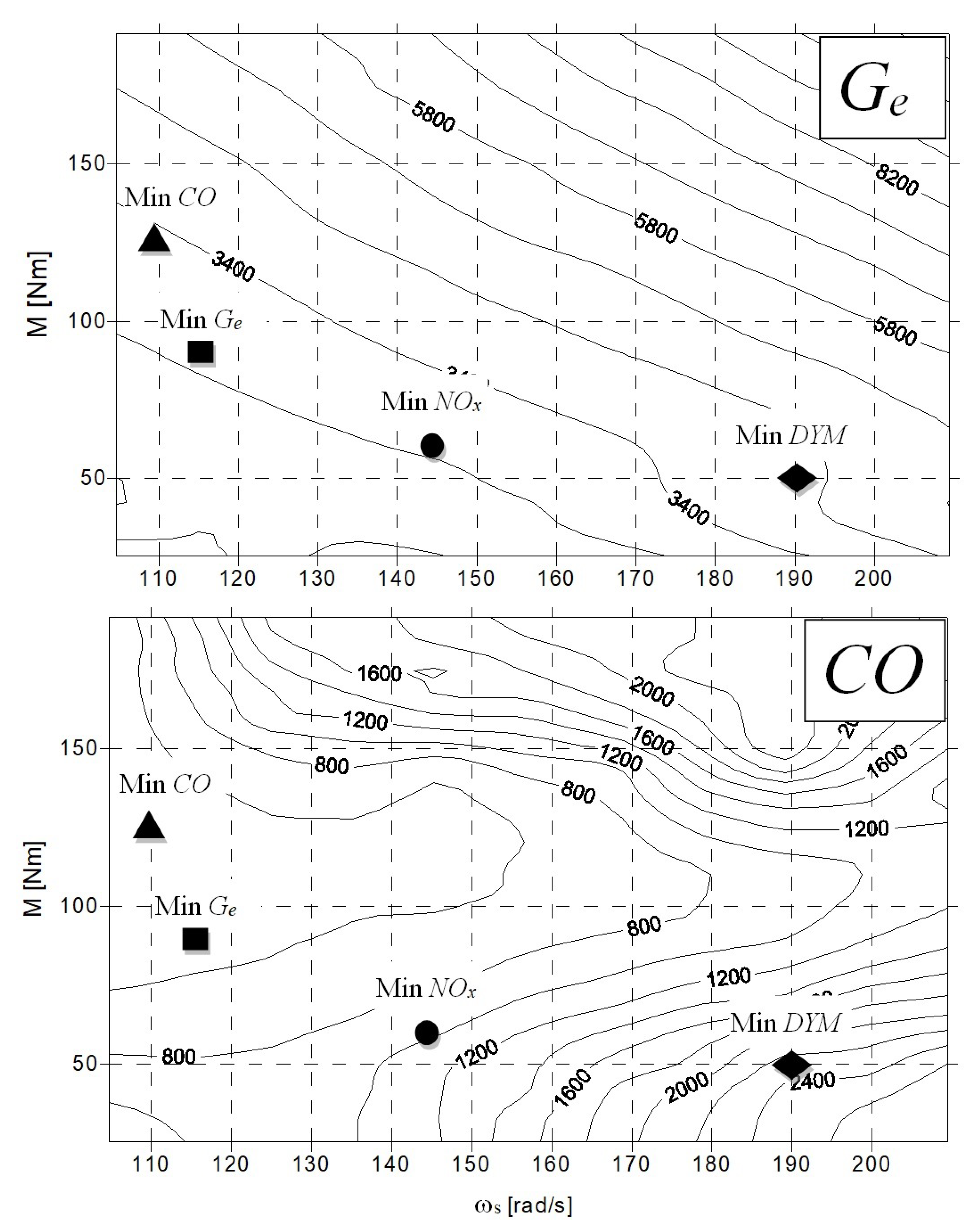
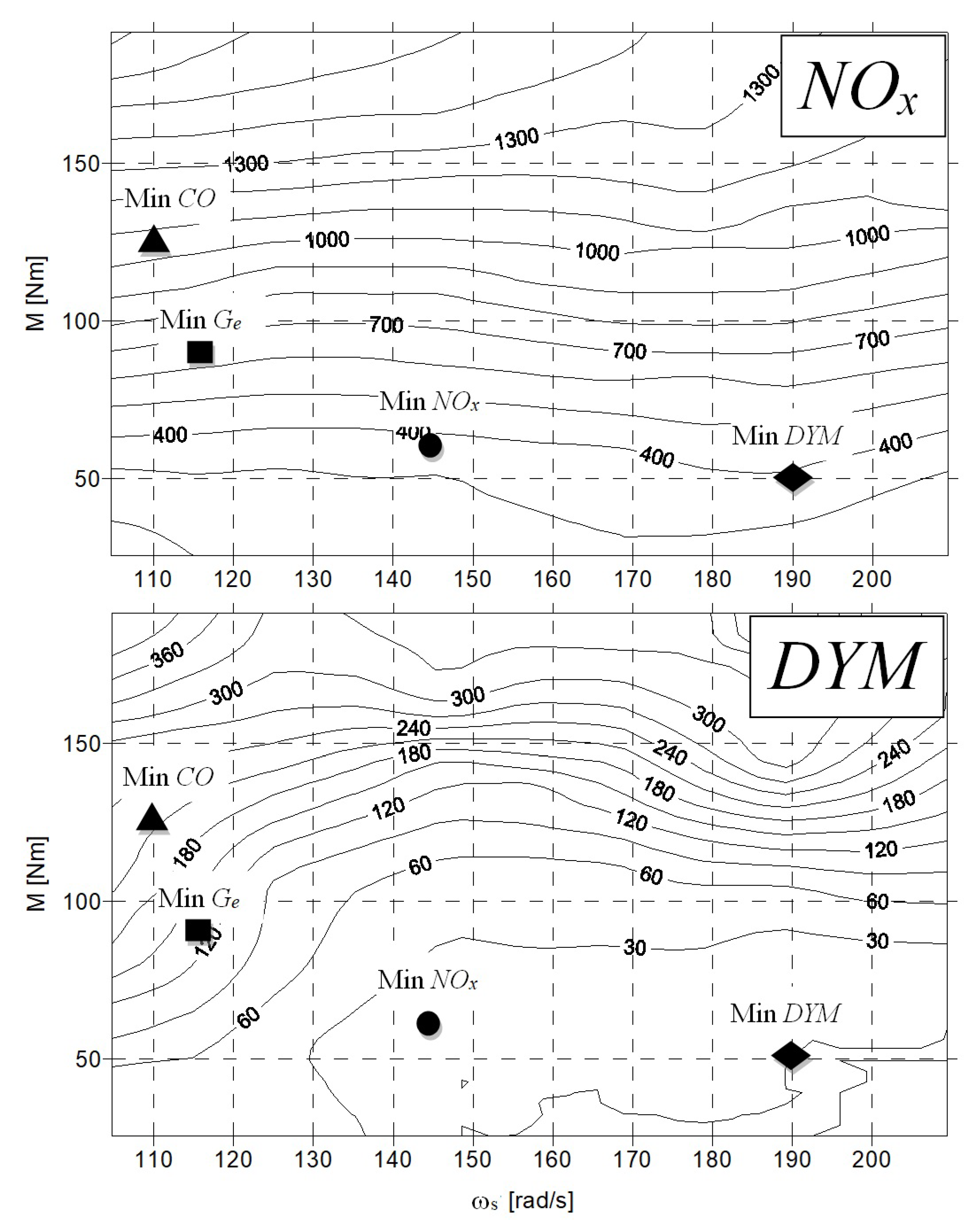
  • Universal combustion engine characteristics concerning:
    • Fuel consumption G c in the work cycle [ g cycle ] ;
    • The carbon oxide C O content in the exhaust gas [ppm];
    • The nitrogen oxides N O x content in the exhaust gas [ppm];
    • The exhaust gas opacity D Y M [CD BOSCH].
  • The characteristics of the hydrostatic units:
    • Torque M p , M s h [Nm];
    • Angular velocity ω p , ω s h [ rad s ] ;
    • Capacity or displacement q p m a x , q s h m a x [ m 3 s ] .
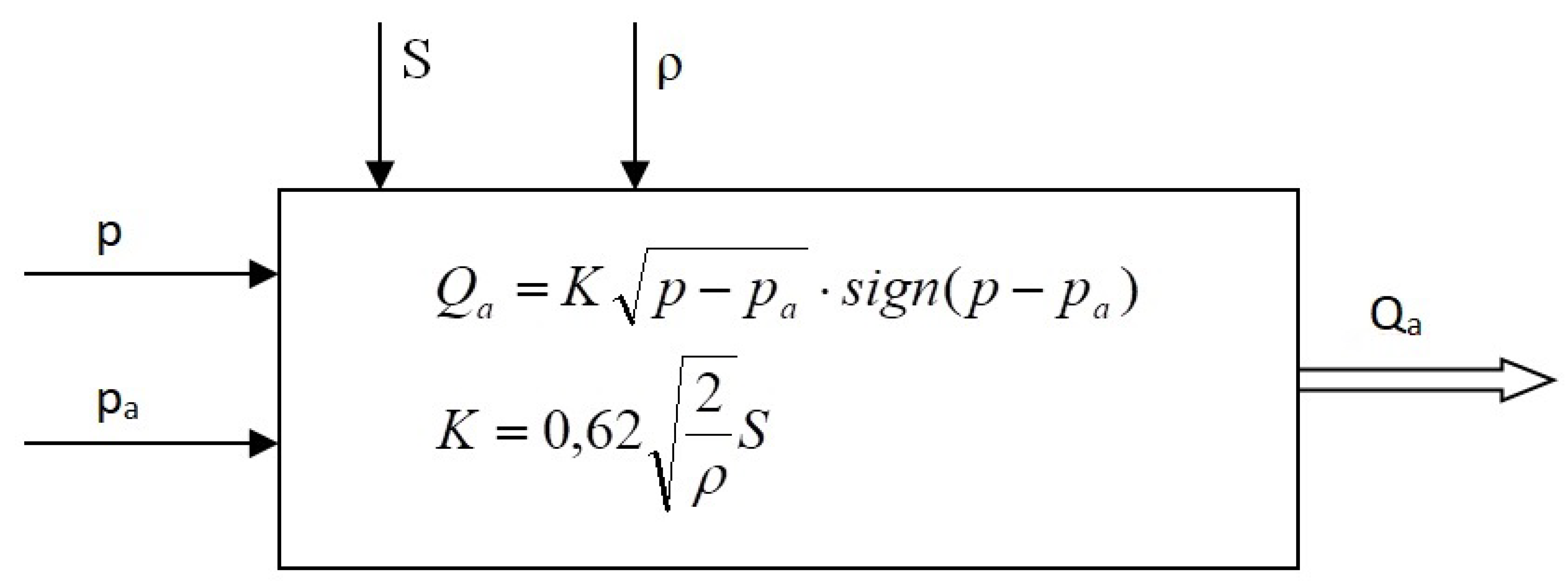
  • The specifications of the hydraulic accumulator:
    • Total accumulator capacity V g m a x [ m 3 ] .
  • Losses in the hydraulic system.
The program yields:
  • The duty points M s p , ω s p of a combustion engine selected with regard to the optimization criterion, e.g., minimal fuel consumption at point G c , minimal nitrogen oxides N O x in the exhaust gas, etc.;
  • Cycle control paths ϵ p and ϵ s h for hydrostatic units;
  • Initial accumulator pressure p a 0 [Pa];
  • The accumulator pre-charge pressure p g w s t [Pa] (gas pressure in the accumulator not connected to the hydraulic system) [80].

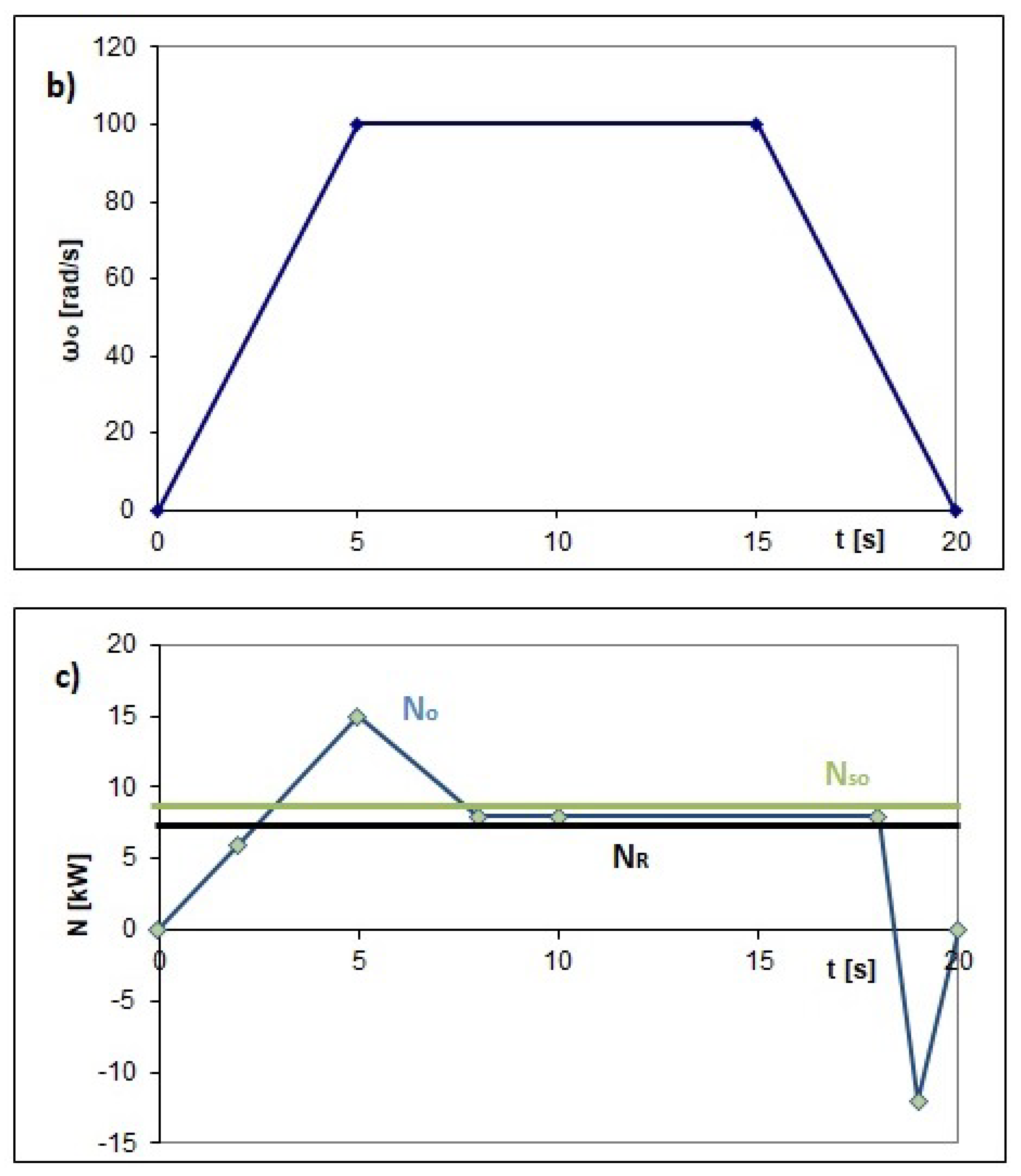
3.1.2. Mathematical Models Used in Kinetostatic Method Algorithm

In order to demonstrate the operating principle of the program, only the procedure for determining the operating parameters of a hydrostatic drive system with a hydraulic accumulator is presented here [2,80,81,82]. The hydrostatic unit settings ϵ p and ϵ s h in cycle time t i are determined by solving regression Equation (1) for the shaft torque of a hydrostatic pump and motor (Figure 8).
A regression function (Figure 9) is used to calculate the capacity Q p of the hydrostatic pump and the displacement Q s h of the hydrostatic engine.
The displacement Q a of the hydraulic accumulator is described by the relation shown in the Figure 10.

3.2. Description of Program Operation

In order to perform the computations one must define the full set of universal combustion engine characteristics: the fuel consumption G c per work cycle, the carbon oxide C O content in the exhaust gas, the nitrogen oxides N O x content and the exhaust gas opacity D Y M . These data, together with the characteristics of angular velocity ω o and load torque M o as a function of time, are placed in a file. In addition, the total accumulator capacity V g m a x is declared.
When executed, the program calculates the average load power, and then it retrieves from the file the combustion engine duty points satisfying the condition:
N s p i N o b c
where i is the next tested duty point ( s p : primary source of energy; o b c : load).
In the next step, computations are performed for all the retrieved duty points for the whole load cycle, and it is checked whether the accumulator’s energy at the start of the cycle differs from that at the end of the cycle by no more than 500 [J], which amounts to less than 1% of the initial value:
E a E a 0 500 [ J ]
where E a 0 is the accumulator’s energy at the start of the cycle and E a is the accumulator’s energy at the end of the cycle.
If the above condition is satisfied, the selected duty point is entered into a table as one of the points for which the given machine work cycle is feasible. Then, the next point for which relation (2) is satisfied is selected for computations.
This procedure is repeated for several values of the initial pressure p prevailing in the system, equal to the initial pressure p a 0 of the hydraulic accumulator. The next pressure values are calculated using an iteration with a 5 MPa step. The latter is one of the program parameters the lowering of which results in finding a larger number of feasible combustion engine duty points, albeit with a longer computational time.
The combustion engine’s duty points determined in this way are sorted according to the set optimization criterion, e.g., minimal fuel consumption G c m i n per cycle, and are saved to an output file, together with the initial system operation parameters and accumulator precharge p a w s t .
Once the computations are completed, their results are displayed in the form of graphs of the hydrostatic settings ϵ p and ϵ s h (Figure 11), load and combustion engine power and accumulator energy versus time. In addition, all the parameters for a selected engine duty point, the initial accumulator charge level and the initial operating parameters of the system are displayed. The graphic design of the software for calculating multisource system control parameters using the refined kinetostatic method is presented in Figure 11.

3.3. Results Yielded by Kinetostatic Method

The first set of computations were performed for the load shown in Figure 12. Table 1 contains feasible multisource system duty points and their parameters yielded by the refined kinetostatic method for a hydraulic accumulator with total volume V a = 0.005 [ m 3 ] . The points are ordered according to the criterion of fuel consumption in cycle G c .
Figure 13 shows the distribution of the feasible duty points of the combustion engine (Table 1) on its external characteristic, determined for an accumulator with capacity V a = 0.005 [ m 3 ]. As one can see, the points are arranged along the so-called constant power hyperbola. Depending on the criterion, a point optimal for this criterion can be selected.
The optimal combustion engine duty points according to the considered criteria for load I and the accumulator capacity V a = 0.005 [ m 3 ] are presented in Table 2.
The above procedure was also applied to the system with other gas hydraulic accumulator capacities.
From the data contained in Table 1, Table 2, Table 3, Table 4, Table 5, Table 6, Table 7, Table 8, Table 9, Table 10, Table 11 and Table 12, obtained for six hydraulic accumulator capacities, the best duty points for a given criterion were selected. The optimal combustion engine duty points for four optimization criteria and load I are presented in Table 13.
Figure 14 illustrates the influence of gas hydraulic accumulator capacity on the values of the parameters for a particular criterion (Table 1, Table 2, Table 3, Table 4, Table 5, Table 6, Table 7, Table 8, Table 9, Table 10, Table 11 and Table 12) at the same load (load I). The lowest fuel consumption ( G c ) per work cycle for load I will characterize the system with a 0.005 [ m 3 ] capacity accumulator, with a consumption amounting to 14.7 [ g cycle ] . For an accumulator capacity of 0.02 [ m 3 ] , the fuel consumption G c will be highest, amounting to 15.94 [ g cycle ] .
In the case of carbon monoxide ( C O ) emissions, the minimal value, amounting to 476 [ppm], will be reached for the system with an accumulator of capacity 0.03 [ m 3 ] , whereas the maximum emissions, amounting to 603 [ppm], will occur when an accumulator of capacity 0.04 [ m 3 ] is used in the system.
In the case of the minimal nitrogen oxides ( N O x ) emissions criterion, the minimum, amounting to 346 [ppm], will be reached for the system with an accumulator capacity of 0.01 [ m 3 ] , whereas the maximum, amounting to 476 [ppm], will occur at an accumulator capacity of 0.03 [ m 3 ] .
In the case of the exhaust gas opacity ( D Y M ) criterion, the extrema, i.e, the minimum equal to 0.3 [CD BOSCH] and the maximum equal to 10.3 [CD BOSCH], were reached for accumulator capacities of 0.005 [ m 3 ] and 0.04 [ m 3 ] , respectively. This means that through a proper choice of multisource drive system accumulator capacity for the set load one can achieve better parameters for the selected criterion. For criterion G e , the difference between the minimum and maximum fuel consumption per cycle amounts to 8.4%, for C O it is 26.7 %, for N O x it is 35.1% and for D Y M it is as much as 3000%. The greatest benefits were gained for the opacity criterion. These analyses show that a change in accumulator capacity can result in a very significant improvement in the parameters for a particular criterion. The above example supports the thesis advanced in this paper and constitutes its preliminary proof (Figure 15 and Figure 16).
The universal combustion engine characteristics and the marked optimal duty points according to particular criteria for load I are presented in Figure 8. An analysis of the locations of the points shows that they lie in different parts of the engine characteristic, and this is due to the fact that the optima for the particular criteria considered in this paper are located in different areas of the external characteristic of the engine.

4. Conclusions

The benefits that can be gained through the use of appropriate secondary energy source parameters (accumulator volume V g and initial gas pressure p g ) for a given work cycle of a machine working in a closed space were presented for particular control criteria from the point of view of the energy and ecological performance of a multisource hydrostatic drive system. The method of replacing classic drives working indoors with multisource drives described in this paper makes it possible to reduce energy consumption and/or exhaust gas emissions and/or opacity through the recovery of kinetic and/or potential energy and the stabilization of the primary energy source.
The obtained results show that by replacing classic drive systems with multisource systems, one can obtain the following reductions for the same load characteristics: fuel consumption by up to 30%, carbon oxide ( C O ) emissions by 10–20 times and similar values for nitrogen oxides ( N O x ) emissions and opacity ( D Y M ). Furthermore, owing to primary energy source stabilization, the life of the drive units can be extended by 2–3 times. The above savings mean that multisource drive systems constitute a real alternative to the currently increasingly common electric drives.

Funding

This research was supported by Wrocław University of Science and Technology, Institute of Machines Design and Operation.

Institutional Review Board Statement

Not applicable.

Informed Consent Statement

Not applicable.

Data Availability Statement

Not applicable.

Conflicts of Interest

The author declare no conflict of interest. The funders had no role in the design of the study, in the collection, analyses, or interpretation of data, in the writing of the manuscript or in the decision to publish the results.

References

  1. Stosiak, M. The impact of hydraulic systems on the human being and the environment. J. Theor. Appl. Mech. 2015, 53, 409–420. [Google Scholar] [CrossRef] [Green Version]
  2. Kędzia, K. An algorithm for the determination of the control parameters of a multisource drive system. Tech. Trans. 2017, 3, 173–182. [Google Scholar]
  3. Karpenko, M.; Bogdevičius, M. Review of energy-saving technologies in modern hydraulic drives. Moksl.-Liet. Ateitis: Statyb. Transp. Aviac. Technol. 2017, 9, 553–558. [Google Scholar] [CrossRef] [Green Version]
  4. Albright, H.D.; Rollins, W.R. Hybrid Power System for Driving a Motor Vehicle. U.S. Patent 4588040, 13 May 1986. [Google Scholar]
  5. Chrostowski, H. Modelowanie rozpływu mocy w hydrostatycznych wieloźródłowych układach napędowych. In Prace Naukowe Centralnego Programu Badan Podstawowych 02.05; Chrostowski, H., Ed.; Politechnika Wrocławska: Wrocław, Poland, 1990; pp. 32–58. [Google Scholar]
  6. Lewandowski, W.M. Proekologiczne Odnawialne Zródła Energii; WNT: Warszawa, Poland, 2007. [Google Scholar]
  7. Ocioszyński, J. Elektroenergetyka Hybrydowych Elektromechanicznych Układów Napędowych Pojazdów; Wydawnictwa Politechniki Warszawskiej: Warszawa, Poland, 1981. [Google Scholar]
  8. Pawelski, Z. Modelowanie i Obliczanie Napędu Hydrobusu; Monografie Politechniki Łódzkiej: Łódź, Poland, 2000. [Google Scholar]
  9. Chrostowski, H. Podstawy Budowy Mechano-Hydraulicznych Układów Napędowych z Akumulacją Energii- Sprawozdanie Merytoryczne z Projektu Badawczego KBN nr 1309/P4/92/02; Politechnika Wrocławska: Wrocław, Poland, 1998. [Google Scholar]
  10. Klop, R.; Ivantysynova, M. Investigation of Noise Sources on a Series Hybrid Transmission. Int. J. Fluid Power 2011, 12, 17–30. [Google Scholar] [CrossRef]
  11. Ocioszyński, J. Metody Energetyczne Określania Parametrów Hybrydowego Układu Napędowego Pojazdów i Maszyn Roboczych; I Konferencja Naukowa Mechanizacji Budownictwa: Warszawa, Poland, 1981. [Google Scholar]
  12. Sradomski, W. Metoda Oceny Charakterystyk Energetycznych i Ekologicznych Układu Silnik Spalinowy—Przekładnia Hydrostatyczna dla Widmowej Postaci Obciążeń; Praca doktorska: Wrocław, Poland, 2002. [Google Scholar]
  13. Szumanowski, A. (Ed.) Układy Napędowe z Akumulacją Energii; PWN: Warszawa, Poland, 1990. [Google Scholar]
  14. Malinowski, J. (Ed.) Analiza Widm Obciążeń Osprzętów Koparek; Wydawnictwa Politechniki Warszawskiej: Warszawa, Poland, 1990. [Google Scholar]
  15. Szumanowski, A. Czas Energii; WKiŁ: Warszawa, Poland, 1988. [Google Scholar]
  16. Andersson, J.D.; Jemma, C.A.; Bosteels, D.; Searles, R.A. Particle Emissions From a EU3 Heavy-duty Diesel Engine with Catalyst-based Diesel Particle Filter and Selective Catalytic Reduction System: Size, Number, Mass und Chemistry, 11. In Proceedings of the Aachener Kolloquium Fahrzeug und Motorentechnik, Aachen, Germany, 7–9 October 2002. [Google Scholar]
  17. Fice, M. Zarządzanie Rozpływem Energii w Napędzie Hybrydowym; Praca doktorska: Gliwice, Poland, 2010. [Google Scholar]
  18. Fice, M.; Setlak, R. Analiza energetyczna rzeczywistych cykli jazdy. Zesz. Probl. 2011, 90, 99–103. [Google Scholar]
  19. Siłka, W. Energochłonność Ruchu Samochodu; WNT: Warszawa, Poland, 1997. [Google Scholar]
  20. Szumanowski, A. Akumulacja Energii w Pojazdach; WKiŁ: Warszawa, Poland, 1984. [Google Scholar]
  21. Siłka, W. Teoria Ruchu Samochodu; WNT: Warszawa, Poland, 2002. [Google Scholar]
  22. Żółtowski, A. Pomiar emisji w warunkach nieustalonych. J. Kones Intern. Combust. Engines 2003, 10, 3–4. [Google Scholar]
  23. Kędzia, K.; Chrostowski, H. Optimization of work parameters of hydrostatic multisources power systems in term of selected criteria. In Proceedings of the Riadenie Tekutinovych Systemov, V. Vedecka a Odborna Konferencia, Terchova-Biely Potok, Slovensko, 25–27 October 2000; pp. 19–23. [Google Scholar]
  24. Kędzia, K.; Chrostowski, H. Control of hydrostatic multisources power systems in term of selected criteria. In Proceedings of the International Carpathian Control Conference, ICCC 2001, Krynica, Poland, 22–25 May 2001; pp. 609–614. [Google Scholar]
  25. Stryczek, S. Napęd Hydrostatyczny tom I i II; WNT: Warszawa, Poland, 1995. [Google Scholar]
  26. Van de Ven, J.D.; Olson, M.W.; Li, P.Y. Development of a hydro-mechanical hydraulic hybrid drive train with independent wheel torque control for an urban passenger vehicle. In Proceedings of the International Fluid Power Exposition, Las Vegas, NV, USA, 14–18 March 2008. [Google Scholar]
  27. Kucybała, P. Akumulator Hydropneumatyczny Jako Wtórne Zródło Energii w Przkładni Hydrostatycznej, Praca Doktorska; Politechnika Krakowska: Kraków, Poland, 2011. [Google Scholar]
  28. Rannow, M.; Li, P.; Chase, T.; Tu, H.; Wang, M. Optimal design of a high-speed on/off valve for a hydraulic hybrid vehicle application. In Proceedings of the 7th International Fluid Power Conference, Aachen, Germany, 22–24 March 2010. [Google Scholar]
  29. Sim, T.P.; Li, P.Y. Analysis and Control Design of a Hydro-Mechanical Hydraulic Hybrid Passenger Vehicle. In Proceedings of the ASME 2009 Dynamic Systems and Control Conference No. 2763, Hollywood, CA, USA, 12–14 October 2009. [Google Scholar]
  30. Balawender, A. Analiza Energetyczna i Metodyka Badań Silników Hydraulicznych Wolnoobrotowych, Zeszyty Naukowe Politechniki Gdańskiej nr 422; Mechanika nr LIV: Gdańsk, Poland, 1988. [Google Scholar]
  31. Cheong, K.L.; Li, P.Y.; Chase, T.R. Optimal Design of Power-Split Transmission for Hydraulic Hybrid Passenger Vehicles. In Proceedings of the American Control Conference, San Francisco, CA, USA, 29 June–1 July 2011. [Google Scholar]
  32. Cheong, K.L.; Li, P.Y.; Chase, T.R. Comparison between input coupled and output coupled power-split configurations in hybrid vehicles. In Proceedings of the 2011 International Fluid Power Exhibition (IFPE), Paper number:10.2, Las Vegas, NV, USA, 14–18 March 2011. [Google Scholar]
  33. Dindorf, R. Napędy Płynowe Hydrostatyczne i Pneumatyczne. Podstawy Teoretyczne i Metody Obliczania; Wydawnictwo Politechniki Świętokrzyskiej: Kielce, Poland, 2009. [Google Scholar]
  34. Grandall, D.R. Performance and Efficiency of Hydraulic Pumps and Motors. Master’s Thesis, Department of Mechanical Engineering, University of Minnesota, Saint Paul, MN, USA, 2010. [Google Scholar]
  35. Paszota, Z. Uściślenie Teoretyczne Związane z Wyznaczaniem Strat i Sprawności dla Przekładni Hydrostatycznych, W: A. Garbacik (red.) W: Kierunki Rozwoju Napędów Hydraulicznych i Konstrukcji Maszyn Roboczych; Fluid Power Net Publication: Kraków, Poland, 1999. [Google Scholar]
  36. Triet, H.H.; Ahn, K.K. Comparison and assessment of hydraulic energy-saving system for hydrostatic drives. Proc. Inst. Mech. Eng. Part J. Syst. Control. Eng. 2011, 225, 21–34. [Google Scholar] [CrossRef]
  37. Dietrich, M. (Ed.) Podstawy Konstrukcji Maszyn, Part 2; WNT: Warszawa, Poland, 1999. [Google Scholar]
  38. Moszyński, W. Wykład Elementów Maszyn, cz. III, Napędy; Państwowe Wydawnictwa Techniczne: Warszawa, Poland, 1965. [Google Scholar]
  39. Śliwiński, P. The methodology of design of axial clearances compensation unit in hydraulic satellite displacement machine and their experimental verification. Arch. Civ. Mech. Eng. 2019, 19, 1163–1182. [Google Scholar] [CrossRef]
  40. Kędzia, K.; Chrostowski, H. Self-Locking Phenomenon in Hydrostatic Motor Working as Reversible Unit in Multisources Hydrostatic Driving System; Hydraulika a Pneumatika: Žilina, Slovakia, 2006. [Google Scholar]
  41. Kornberger, Z. Przekładnie Slimakowe, Konstrukcja, Wykonanie, Sprawdzanie; WNT: Warszawa, Poland, 1971. [Google Scholar]
  42. Łaguna, J.; Łypacewicz, K. Połączenia Srubowe i Nitowe; Arkady: Warszawa, Poland, 1986. [Google Scholar]
  43. Orlik, Z.; Surowiak, W. Części Maszyn, cz. 1; Wydawnictwa Szkolne i Pedagogiczne: Warszawa, Poland, 1976. [Google Scholar]
  44. Osiński, Z.; Bajon, W.; Szucki, T. Podstawy Konstrukcji Maszyn; Państwowe Wydawnictwa Naukowe: Warszawa, Poland, 1978. [Google Scholar]
  45. Szydelski, Z. Hydrauliczna Akumulacja Energii w Napędach Pojazdów, Auto Technika Motoryzacyjna. 1984.
  46. Szumanowski, A. Opracowanie Metody Właściwego Doboru Układu Elektromaszynowego do Napędu Pojazdów Samochodowych. Praca Doktorska; Politechnika Warszawska: Warszawa, Poland, 1978. [Google Scholar]
  47. Grabowiecki, K. (Ed.) Symulacja Procesów Energetycznych w Napędach Wieloźródłowych; Wydawnictwa Politechniki Warszawskiej: Warszawa, Poland, 1990. [Google Scholar]
  48. Grzegorek, W. Przekładnie o ciąGłej Zmianie Przełożenia (CTV) w Układach Napędowych Pojazdów; Wydawnictwo PK: Kraków, Poland, 2011. [Google Scholar]
  49. Guzowski, A.; Sobczyk, A. Modernizacja Hydrostatycznego Układu Napędowego Jazdy Pod Katem Poprawy Jakości Sterowania, Inżynieria Maszyn, nr 2012 nr 4; Wydawnictwo Wrocławskiej Rady FSNT NOT: Wrocław, Poland, 2012; p. 14. ISSN 1426-708X. [Google Scholar]
  50. Herzog, S.; Zink, M.; Michael, P. Hydraulic Fluid Viscosity Selection for Improved Fuel Economy. SAE J. Commer. Veh. 2009, 2, 61–65. [Google Scholar] [CrossRef]
  51. Hippalgaonkar, R.; Ivantysynova, M.; Zimmerman, J. Fuel Savings of a Mini-Excavator through a hydraulic hybrid displacement controlled system. In Proceedings of the 8th IFK International Conference on Fluid Power, Dresden, Germany, 8–10 March 2012; Volume 2, pp. 139–154. [Google Scholar]
  52. Hippalgaonkar, R.; Ivantysynova, M. A Series-Parallel Hydraulic Hybrid Mini-Excavator with Displacement Controlled Actuators. In Proceedings of the 13th Scandinavian International Conference on Fluid Power (SICFP2013), Linkoping, Sweden, 3–5 January 2013. [Google Scholar]
  53. Hoffmann, W.; Hesse, K. Digitale Simulation des Dynamischen Verhaltens Hydraulischer Gerate. Oelhydraul. Pneumat 1980, 24, 159–166. [Google Scholar]
  54. Zimmerman, J.; Hippalgaonkar, R.; Ivantysynova, M. Optimal Control for the Series-Parallel Displacement Controlled Hydraulic Hybrid Excavator. In Proceedings of the 2011 ASME Dynamic Systems and Control Conference and Bath/ASME Symposium on Fluid Power and Motion Control, Arlington, VA, USA, 31 October–2 November 2011. [Google Scholar]
  55. Kędzia, K. Development of kinetostatic method algorithm of control system of multisource driving system. Hidraulica 2009, 3/4, 39–45. [Google Scholar]
  56. Kędzia, K.; Chrostowski, H. Modelling of an energy-saving hybrid hydrostatic driving system. In Proceedings of the Hydraulics and Pneumatics 98, the 16th International Conference, Czech Machinery Association, Czech Association for Hydraulics and Pneumatics, Brno, Czech Republic, 30 Septermber–2 October 1998; pp. 158–164. [Google Scholar]
  57. Kędzia, K.; Chrostowski, H. Modelowanie energooszczędnego hybrydowego hydrostatycznego układu napędowego. In Proceedings of the Symulacja Procesów Dynamicznych, SPD-10, Prace X sympozjum. PTETiS Oddział Warszawski, Wydział Elektryczny PWarsz, Kościelisko, Poland, 15–19 June 1998; pp. 67–72. [Google Scholar]
  58. Kędzia, K.; Chrostowski, H. Modelowanie energooszczędnych hydrostatycznych wieloźródłowych układów napędowych. In Proceedings of the Napędy i Sterowania Hydrauliczne’99, Konferencja Naukowo-Techniczna, Ośrodek Doskonalenia Kadr SIMP, Wrocław-Polanica Zdrój, Poland, 18–20 May 1999; pp. 226–236. [Google Scholar]
  59. Kędzia, K.; Chrostowski, H. Optymalizacja parametrów pracy hydrostatycznego wieloźródłowego układu napędowego ze względu na wybrane kryteria. In Proceedings of the Problemy Rozwoju Maszyn Roboczych, XIV Konferencja Naukowa, Zakopane, Poland, 22–25 January 2001; pp. 73–80. [Google Scholar]
  60. Kombinat PZL HYDRAL we Wrocławiu: Dokumentacja modelowo obliczeniowa możliwości zastosowania zmodernizowanego wzmacniacza AW10 do jednostki tłokowo osiowej IT3-32.
  61. Kollek, W.; Osiński, P. Modeling and Design of Gear Pumps, Oficyna Wyd; Politechniki Wrocławskiej: Wrocław, Poland, 2009. [Google Scholar]
  62. Meyer, J.J.; Stelson, K.A.; Hencey, B.; Alleyne, A.G. Power management strategy for a hydraulic hybrid passenger vehicle using stochastic dynamic programming. In Proceedings of the 7th International Fluid Power Conference, Aachen, Germany, 1 March 2010. [Google Scholar]
  63. Sobczyk, A. Improvement of Hydraulic System Efficiency by Means of Energy Recuperation; Wydawnictwa Politechniki Krakowskiej: Kraków, Poland, 2011. [Google Scholar]
  64. Sobczyk, A.; Pobędzia, J.; Kucybała, P. Badania symulacyjne hydraulicznego układu odzysku energii w pojazdach i maszynach roboczych. In Proceedings of the XII Warsztaty Naukowe Polskiego Towarzystwa Symulacji Komputerowej, Sarbinowo, Poland, 15–19 September 2005. [Google Scholar]
  65. Sprengel, M.; Ivantysynova, M. Investigation and Energetic Analysis of a Novel Hydraulic Hybrid Architecture for On-Road Vehicles. In Proceedings of the 13th Scandinavian International Conference on Fluid Power (SICFP2013), Linkoping, Sweden, 3–5 January 2013. [Google Scholar]
  66. Kucybała, P.; Pobędzia, J.; Sobczyk, A. Określenie sprawności hydraulicznego układu odzysku energii w mechanizmie jazdy. In Proceedings of the Problemy Rozwoju Maszyn Roboczych, Zakopane, Poland, 27–31 January 2006. [Google Scholar]
  67. Kumar, R.; Ivantysynova, M. An Instantaneous Optimization Based Power Management Strategy to Reduce Fuel Consumption in Hydraulic Hybrids. Int. J. Fluid Power 2011, 12, 15–25. [Google Scholar] [CrossRef]
  68. Michael, P.; Wanke, T.; Devlin, M. An Investigation of Hydraulic Fluid Properties and Low-Speed Motor Efficiency. In Proceedings of the 7th International Fluid Power Conference, Aachen, Germany, 22–24 March 2010; Volume 3, pp. 341–353. [Google Scholar]
  69. Ostaszewicz, J. Energochłonność Transportu Miejskiego; WKiŁ: Warszawa, Poland, 1984. [Google Scholar]
  70. Paszota, Z. Podwyższenie sprawności energetycznej kierunkiem rozwoju napędu hydrostatycznego, Hydraulika i Pneumatyka 5/1998.
  71. Siłka, W. Analiza Wpływu Parametrów Cyklu Jezdnego na Energochłonność Ruchu Samochodu; Polska Akademia Nauk, Oddział w Krakowie: Kraków, Poland, 1998. [Google Scholar]
  72. Śliwiński, P. Methods of Determining Pressure Drop in Internal Channels of a Hydraulic Motor. Energies 2021, 14, 5669. [Google Scholar] [CrossRef]
  73. Cristescu, C. Recuperarea Energiei Cinetice la Franarea Autovehiculelor; Editura AGIR: Bucharest, Romania, 2008. [Google Scholar]
  74. Dindorf, R. Zmniejszenie Zużycia Energii w Systemach Sprężonego Powietrza. Pneumatyka 2011, nr2, 30–35. [Google Scholar]
  75. Du, Z.; Cheong, K.L.; Li, P.Y.; Chase, T.R. Fuel Economy Comparisons of Series, Parallel and HMT Hybrid Architectures. In Proceedings of the 2013 American Control Conference, Washington, DC, USA, 17–19 June 2013. [Google Scholar]
  76. Kędzia, K.; Chrostowski, H. Sterowanie hydrostatycznym hybrydowym układem napędowym. Hydraul. Pneumatyka 2006, nr2, 35–38. [Google Scholar]
  77. Kędzia, K.; Pyrc, M. Modelowanie wieloźródłowego układu napędowego z hydrostatycznym przetwarzaniem strumienia energii. In Proceedings of the 19. Międzynarodowe Sympozjum Naukowe Studentów i Młodych Pracowników Nauki, PZielonogórs, Zielona Góra, Poland, 28–29 March 1997; pp. 168–172. [Google Scholar]
  78. Kędzia, K.; Matus, M. Modelowanie i symulacja wieloźródłowego hydrostatycznego układu napędowego. In Proceedings of the 20. Międzynarodowe Sympozjum Naukowe Studentów i Młodych Pracowników Nauki, PZielonogórska, Zielona Góra, Poland, 13–14 May 1998; pp. 151–156. [Google Scholar]
  79. Śliwiński, P. Determination of the Theoretical and Actual Working Volume of a Hydraulic Motor. Energies 2020, 13, 5933. [Google Scholar] [CrossRef]
  80. Kędzia, K.; Chrostowski, H. The analysis of pneumo-hydraulic accumulator efficiency, applied as element of hybrid driving system. Sci. Pap. Univ. Pardubic. Ser. Jan Perner Transp. Fac. 2004, 10, 93–99. [Google Scholar]
  81. Kędzia, K.; Chrostowski, H. Electrohydraulic controller as a hydrotronic element of driving system. In Proceedings of the 4th FPNI—PhD Symposium, Sarasota, FL, USA, 13–17 June 2006; Volume 2, pp. 523–532. [Google Scholar]
  82. Osiński, P.; Chruścielski, G. Strength calculations of an element compensating circumferential backlash in the external gear pump. J. Theor. Appl. Mech. 2016, 54, 251–262. [Google Scholar] [CrossRef] [Green Version]
Figure 1. Exemplary operation cycle of intercity bus (N: power; ω : angular velocity) [2,23,24].
Energies 15 05132 g001
Figure 2. Chart showing vehicle speed during test conducted according to ECE regulations, covering an urban driving cycle (UDC) and extra-urban driving cycle (EUDC) (v: velocity) [2,21,22].
Energies 15 05132 g002
Figure 3. Schematic diagram of hydrostatic transmission (M: torque; ω : angular velocity; Q: flow ratio; ϵ : hydrostatic unit control; indexes: s p : IC engine; p: hydrostatic pump; s h : hydrostatic motor; 0: load; z: flow through overflow valve) [2].
Energies 15 05132 g003
Figure 4. Block diagram of hybrid drive system: 1: primary energy source; 2: energy accumulator; 3: automatic power control system (UASM); 4: electric traction motor (EST); 5: mechanical gearbox (PM) (N: power; η : efficiency; t: time; indexes: z: primary source of energy; s t : control system; M: traction motor; p: mechanical transmission; A: accumulator; R: recuperation; W: discharging) [2,20].
Energies 15 05132 g004
Figure 5. Diagram of multisource hydrostatic drive system (M: torque; ω : angular velocity; Q: flow ratio; ϵ : hydrostatic unit control; indexes: s p : IC engine; p: hydrostatic pump; s h : hydrostatic motor; o: load; z: flow through overflow valve; A: hydraulic accumulator) [2].
Energies 15 05132 g005
Figure 6. Process algorithm (kinetostatic method) block diagram (M: torque; ω : angular velocity; T: time of cycle; E: energy; E a 1 : energy supplied to the accumulator; E a 2 : energy taken from the accumulator; Δ E t : losses in the hydraulic unit; Δ E a t : energy losses in the accumulation unit; Δ δ a : accumulator energy balance (usually less than 1%); G p : quality criteria; t: time; indexes: 0: load; i: iteration) [2].
Energies 15 05132 g006
Figure 7. Exemplary load diagrams: (a) graph of angular velocity ω o ; (b) graph of load torque M o ; (c) N o : graph of load power; N s o : power at which combustion engine runs in system with stabilization; N R : power at which combustion engine would run if recuperation system were included (N: power; ω : angular velocity; M: torque; indexes: o: load).
Energies 15 05132 g007aEnergies 15 05132 g007b
Figure 8. Block diagram of equations describing shaft torque of hydrostatic pump and engine, where p is the pressure in the system, n p is the rotational speed of the hydrostatic pump, n s h is the rotational speed of the hydrostatic engine, M p is the shaft torque of the hydrostatic pump, M s h is the shaft torque of the hydrostatic engine and d 0 d 6 , c o c 7 are constants [2].
Energies 15 05132 g008
Figure 9. Block diagram of equations for capacity and displacement of hydrostatic pump and engine, where p is the pressure in the system, n p is the rotational speed of the hydrostatic pump, n s h is the rotational speed of the hydrostatic engine, Q p is the capacity of the hydrostatic pump, Q s h is the displacement of the hydrostatic engine and a 1 a 7 , b 1 b 8 are constants [2].
Energies 15 05132 g009
Figure 10. Block diagram of equations describing gas hydraulic accumulator displacement, where K is the hydraulic resistance, p a is the gas pressure in the accumulator, S is the cross-sectional area of the hydraulic tubes, ρ is the density of the fluid and p is the pressure in the system [2].
Energies 15 05132 g010
Figure 11. Graphic layout of software for computing multisource system control parameters, based on refined kinetostatic method [55].
Energies 15 05132 g011
Figure 12. Load I: (a) M o : load torque; (b) ω o : angular velocity of load.
Energies 15 05132 g012
Figure 13. Feasible combustion engine duty points for load I and gas hydraulic accumulator capacity V a = 0.005 [ m 3 ].
Energies 15 05132 g013
Figure 14. Influence of hydraulic accumulator capacity on values of optimization criteria for load I.
Energies 15 05132 g014
Figure 15. Universal characteristics and optimal points according to particular criteria for load I ( G e , C O ).
Energies 15 05132 g015
Figure 16. Universal characteristics and optimal points according to particular criteria for load I ( N O x , D Y M ).
Energies 15 05132 g016
Table 1. Parameters of combustion engine duty points determined for accumulator with capacity V a = 0.005 [ m 3 ] (load I).
No. ω sp
[ rd s ]
M sp
[Nm]
G c
[ g cycle ]
CO
[ppm]
NO x
[ppm]
DYM
[ CD BOSCH ] :
p awst
[MPa]
11109214.7052669616314.63
21417516.937494962914.63
31685017.181656353214.63
411012518.27497106121410.98
51626718.6411574572025.61
613110018.735727116814.63
71735018.821742369521.95
813110919.755587977910.98
91628421.158716162925.61
101945923.502052421121.95
111946724.051710480414.63
121887524.1812925641118.29
131838424.8510746282521.95
Table 2. Optimal combustion engine duty points for load I and accumulator capacity V a = 0.005 [ m 3 ].
No. ω sp [ rd s ] M sp [Nm] G c [ g cycle ] CO [ppm] NO x [ppm] DYM [CD BOSCH]IC Efficiency η sp Hyd. Trans. Efficiency η ph Total Efficiency η c
G c 1119214.705266961630.3530.8350.294
C O 11112518.2749710612140.3860.6130.237
N O x 1685017.1816563531.650.2530.9080.252
D Y M 1935923.5020524210.300.2480.7410.184
Table 3. Parameters of combustion engine duty points determined for accumulator with capacity V a = 0.01 [ m 3 ] (load I).
No. ω sp [ rd s ] M sp [Nm] G c [ g cycle ] CO [ppm] NO x [ppm] DYM [ CD BOSCH ] : p awst [MPa]
11475914.941016346812.94
21159215.3954967213612.94
31477517.627765012317.26
41319217.695966306317.26
513610019.935857105621.57
61835020.692047391425.89
713610920.735628006812.94
81529221.016846683330.20
915210022.286207463825.89
101996725.581855465530.20
112045926.5422043730.321.57
121997526.9915765311417.26
Table 4. Optimal combustion engine duty points for load I and accumulator capacity V a = 0.01 [ m 3 ].
No. ω sp [ rd s ] M sp [Nm] G c [ g cycle ] CO [ppm] NO x [ppm] DYM [CD BOSCH]IC Efficiency η sp Hyd. Trans. Efficiency η ph Total Efficiency η c
G c 1268415.92603561740.3390.8030.272
C O 10512517.4146710782350.3860.6440.249
N O x 1686719.361230467210.2980.7510.224
D Y M 2047528.10163650710.300.2810.5490.154
Table 5. Parameters of combustion engine duty points determined for accumulator with capacity V a = 0.02 [ m 3 ] (load I).
No. ω sp [ rd s ] M sp [Nm] G c [ g cycle ] CO [ppm] NO x [ppm] DYM [ CD BOSCH ] : p awst [MPa]
11525915.9411323601012.94
210512517.41476107823512.94
311512519.12518104419325.89
41686719.3612304672130.20
512611719.8055889511517.26
61835020.6920473914.330.20
71739224.598357213412.94
82047528.10163650710.330.20
Table 6. Optimal combustion engine duty points for load I and accumulator capacity V a = 0.02 [ m 3 ].
No. ω sp [ rd s ] M sp [Nm] G c [ g cycle ] CO [ppm] NO x [ppm] DYM [CD BOSCH]IC Efficiency η sp Hyd. Trans. Efficiency η ph Total Efficiency η c
G c 1525915.9411323609,90.2870.9460.272
C O 10512517.4147610782350.3860.6440.249
N O x 1525915.9411323609.90.2870.9460.272
D Y M 1835020.6920473914.300.2290.9120.209
Table 7. Parameters of combustion engine duty points determined for accumulator with capacity V a = 0.03 [ m 3 ] (load I).
No. ω sp [ rd s ] M sp [Nm] G c [ g cycle ] CO [ppm] NO x [ppm] DYM [ CD BOSCH ] : p awst [MPa]
11268415.926035617417.26
210512517.41476107823517.26
31686719.3612304672125.89
412611719.8055889511517.26
52047528.10163650710.3030.20
Table 8. Optimal combustion engine duty points for load I and accumulator capacity V a = 0.03 [ m 3 ].
No. ω sp [ rd s ] M sp [Nm] G c [ g cycle ] CO [ppm] NO x [ppm] DYM [CD BOSCH]IC Efficiency η sp Hyd. Trans. Efficiency η ph Total Efficiency η c
G c 1268415.92603561740.3390.8030.272
C O 10512517.4147610782350.3860.6440.249
N O x 1686719.361230467210.2980.7510.224
D Y M 2047528.10163650710.300.2810.5480.154
Table 9. Parameters of combustion engine duty points determined for accumulator with capacity V a = 0.04 [ m 3 ] (load I).
No. ω sp [ rd s ] M sp [Nm] G c [ g cycle ] CO [ppm] NO x [ppm] DYM [ CD BOSCH ] : p awst [MPa]
11268415.9260356174125
21686719.36123046721168
32047528.10163650710.3204
Table 10. Optimal combustion engine duty points for load I and accumulator capacity V a = 0.04 [ m 3 ].
No. ω sp [ rd s ] M sp [Nm] G c [ g cycle ] CO [ppm] NO x [ppm] DYM [CD BOSCH]IC Efficiency η sp Hyd. Trans. Efficiency η ph Total Efficiency η c
G c 1268415.92603561740.3390.8030.272
C O 1268415.92603561740.3390.8030.272
N O x 676719.361230467210.2980.7510.224
D Y M 2047528.10163650710.300.2810.5480.154
Table 11. Parameters of combustion engine duty points determined for accumulator with capacity V a = 0.05 [ m 3 ] (load I).
No. ω sp [ rd s ] M sp [Nm] G c [ g cycle ] CO [ppm] NO x [ppm] DYM [ CD BOSCH ] : p awst [MPa]
11268415.926035617417.26
21686719.3612304672117.26
31835020.6920473914.317.26
42047528.10163650710.312.94
Table 12. Optimal combustion engine duty points for load I and accumulator capacity V a = 0.05 [ m 3 ].
No. ω sp [ rd s ] M sp [Nm] G c [ g cycle ] CO [ppm] NO x [ppm] DYM [CD BOSCH]IC Efficiency η sp Hyd. Trans. Efficiency η ph Total Efficiency η c
G c 1268415.92603561740.3390.8030.272
C O 1268415.92603561740.3390.8030.272
N O x 1835020.6920473914.30.2290.9120.209
D Y M 1835020.6920473914.30.2290.9120.209
Table 13. Combustion engine duty points for various optimization criteria and load I.
No. ω sp [ rd s ] M sp [Nm] G c [ g cycle ] CO [ppm] NO x [ppm] DYM [CD BOSCH] V a [ m 3 ] p awst [MPa]
G c 1109214.705266961630.00514.63
C O 105125,1417.4147610782350.0317.26
N O x 1475914.9410163468.40.0112.94
D Y M 1945923.5020522410.30.00521.95
Publisher’s Note: MDPI stays neutral with regard to jurisdictional claims in published maps and institutional affiliations.

