Article

Design and Analysis of Coreless Axial Flux Permanent Magnet Machine with Novel Composite Structure Coils

1
School of Electrical and Information Engineering, Tianjin University, Tianjin 300072, China
2
Suzhou Noah E-Bike Co., Ltd., Suzhou 215000, China
*
Author to whom correspondence should be addressed.
Energies 2022, 15(14), 5162; https://doi.org/10.3390/en15145162
Submission received: 29 May 2022 / Revised: 5 July 2022 / Accepted: 11 July 2022 / Published: 16 July 2022
(This article belongs to the Section F: Electrical Engineering)

Abstract

:
In this paper, a type of novel composite structure coil applied in the coreless stator is proposed and studied to improve the output performance and efficiency of the axial flux permanent magnet (AFPM) machine. In which the effective conductor is changed to be wedge-shaped by the rolling technology so that the turns of coils and filling factor can be further increased, and the ends are kept in the cylinder with a larger diameter to reduce the DC copper loss. Meanwhile, the air region between the double rotors of the machine is also modified to be wedge-shaped, which fully matches the proposed coils and shortens the air gap length. The advantages of performance can be verified by the three-dimensional (3D) finite element analysis (FEA) and analytical method so that the output characteristics of no-load and load can be improved, and the DC copper loss and eddy current loss of coils can be reduced. The coreless AFPM machine finally performs a high efficiency of 95.34% according to these valuable optimizations.

1. Introduction

Compared with the conventional radial flux permanent magnet (PM) machine, the axial flux permanent magnet (AFPM) machine can be used in some special applications such as electric vehicles [1], wind turbine systems [2], and unmanned aerial vehicles [3] due to its short axial size, compact structure, disk-shaped profile, and high efficiency. The AFPM machine has a variety of classical structures; wherein, the configuration with double rotors and a single stator is preferred chiefly [4,5], and the stator core is not necessarily required to form a closed magnetic circuit in the design. By eliminating the iron core of the stator, the coreless AFPM machine has the following advantages [6,7,8]: (1) The quality and cost of the machine are reduced; (2) The loss of the stator core and the cogging torque of the machine are eliminated; (3) The inductance of windings is small, and the influence of the stator current on the air gap flux density is almost negligible; (4) The ability of overload is greatly improved; (5) The arrangement of coils is more flexible and not constrained by slots and teeth of the stator.
The improvement of air gap flux density and the reduction of winding losses are critical issues in the research of AFPM machines with the coreless stator [9]. In general studies, this type of machine has lower air gap density and power density because the air gap length is limited by the axial length of the coreless stator (armature). Several authors have studied that the optimized shape, structure, and parameters of PMs [9,10,11] or the special arrangement of Halbach array PMs [1,3,9,11,12,13] can be used to improve the amplitude and sinusoidal level of the air gap flux density. In [12], the hybrid PM array is proposed and applied in a multi-disc AFPM machine to form a series magnetic circuit to improve the air gap flux density and reduce the rotor mass. The challenges posed by these complex PM structures and arrangements to the fabrication process cannot be ignored.
The significant loss of the coreless AFPM machine is the DC copper loss and eddy current loss in windings, of which the former is generated when the stator current flows through the conductor, and the latter is generated because the coils are directly exposed to the air magnetic field [3,14], especially when operated at a high electric frequency. A number of works have been performed in recent years [15,16,17,18,19,20], that the trapezoidal coils or optimized trapezoidal coils are mostly used in the coreless stator [9,16], compared with the other special shapes such as the circular coils [10] and rhomboidal coils [15], to improve the winding factor The number of turns and width of the conductor can be synchronously optimized, and the structure of unequal width winding is proposed and applied in [16]. The coreless AFPM machine with a type of block coil using 3D printing technology is applied in the collaborative robot to achieve higher output power and efficiency [17]. In [18], with a limited outer diameter of the stator, the length of effective conductors is increased by the improved ends of windings, resulting in the space utilization of the coreless stator and the efficiency of the machine can be improved. In addition, some design optimization procedures are proposed to calculate and reduce the winding losses for ordinary copper wires [19], Litz wires, and PCB traces [20].
However, it is contradictory to improve the air gap flux density and reduce the winding loss in some cases because if the conductor wire diameter is increased, the axial length of the coreless stator may be further increased, the size of the air gap and AFPM machine increased, and the air gap flux density reduced. Furthermore, the difference between the inner diameter and outer diameter of the AFPM machine is relatively significant, resulting in more invalid electromagnetic space at the outer diameter, while the arrangement space at the inner diameter is compact. Therefore, increasing the filling factor of the winding is a more suitable way to improve the efficiency of the AFPM machine.
This paper proposes a new type of armature structure to further contribute to these issues. The optimized coil is a composite structure where the effective side is rolled to be wedge-shaped, which fully matches the space of the wedge-shaped air gap of the coreless AFPM machine and improves the filling factor of the winding and the air gap flux density. The spatial redundancy of the ends can be used, and the wire with a larger diameter can be selected to reduce the phase resistance and DC cooper losses and improve the efficiency of the machine. An AFPM machine with the optimized coreless stator, which is applied in electric bicycles, is designed and studied. The flux density of the non-uniform wedge-shaped air gap and the standard air gap, the filling factor, resistance, and loss of coils with different structures and parameters are calculated and further studied by an analytical method and three-dimensional (3D) finite element analysis (FEA). The distinctive advantages of high air gap flux density and efficiency of the proposed winding structure are confirmed by calculation results.

2. Structure and Parameters

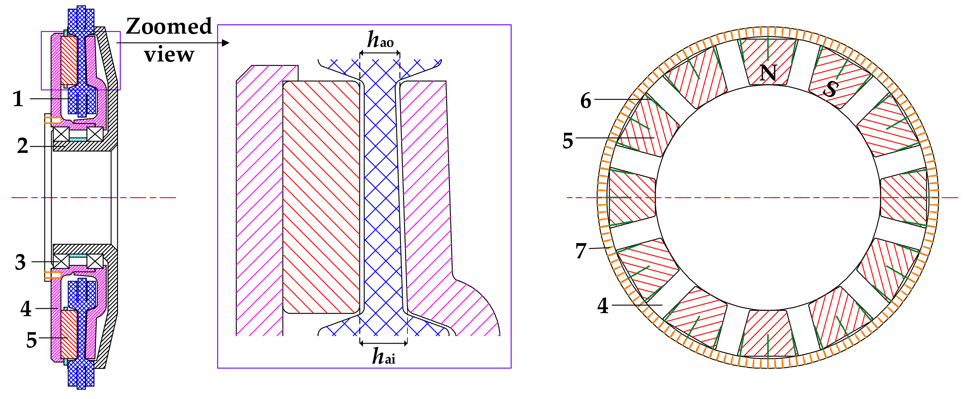
2.1. AFPM Machine with Coreless Stator

The topological structure of the proposed AFPM machine with a coreless stator is shown in Figure 1, which consists of two outer rotor cores made of steel with high mechanical strength and magnetic conductivity, the PMs made of the neodymium iron boron with high coercivity and remanence density, one calendered and encapsulated stator armature in the middle, and the shell made of non-magnetic materials with high mechanical strength. Additionally, the stator support used to provide stable support and heat dissipation for the windings can be made by 3D printing technology. The filled reinforcement sheets are made of rigid materials such as aluminum alloy, stainless steel, ceramic pieces, powder sintering, and thermosetting materials, and are molded and then BMC encapsulated. In order to minimize the cost in the application of electric bicycles, the PMs are only installed on one side of the rotor core, and the other side of the rotor core faces the PMs at a wedge-shaped angle to reduce the length of the air gap and the magnetic circuit. Therefore, the air gap of the AFPM machine with the coreless stator forms a wedge-shaped structure, and the distance between two rotors at the outer diameter is less than that at the inner diameter, as clearly shown in the zoomed view. The flux line starts from the N pole of the PM on one side, flows through the air gap to the rotor core on the other side, then returns to the S pole of the PM from the air gap, finally forming a closed magnetic circuit through the rotor core on the PMs side. The fundamental parameters of the AFPM machine are displayed in Table 1.

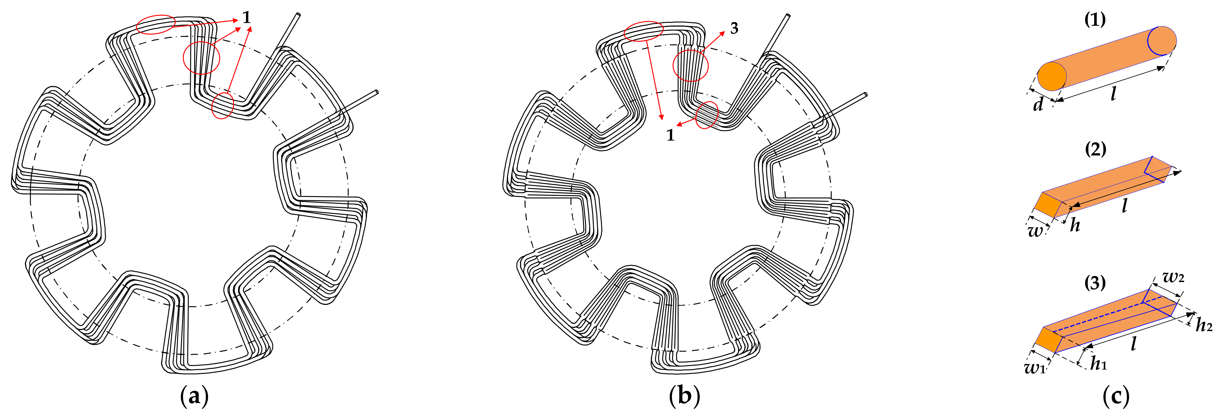
2.2. Novel Composite Structure Coils

The axial length of the armature disc is generally related to the parameters of conductors and the number of coil turns. Especially when the number of turns is constant, the increase in wire diameter can improve the filling factor, reduce the resistance, current density, and DC copper loss of the conductor, and further improve the efficiency of the AFPM machine, but affect the axial length of the coreless stator and machine, which is strictly limited by the application, as described in Section 1. In this section, to solve these technical contradictions, a type of novel composite structure coil applied in the coreless stator is proposed and designed.
The original coils are wound by the round conductors to form the wave winding, as shown in Figure 2a. Both the effective side and the end of the coils are the same cylinder structure in Figure 2(c1). Additionally, each conductor in the winding is fixed to the stator support to maintain stability and heat dissipation. The end conductors are extended out of the stator support and can be soldered, connected in series or parallel outside the housing, making the process simple and reducing production costs as much as possible, and connecting to the controller easily.
Compared with the original coils, the novel composite structure coils are processed by the rolling technology, which is a process that can apply pressure to the metal to extend and reshape it into a specific shape according to the malleability of the metal. The round wire with a larger diameter is rolled in multiple directions on the effective side. The circular section of the conductor is finally extruded into a rectangular section by the rolling technology, die extrusion, or other processes, and all effective conductors can be close to each other without any gaps. Figure 2b shows that the final optimized structure of coils is the novel composite type, in which the effective conductor is rolled to be a wedge-shaped structure as in Figure 2(c3), and the ends of coils keep round wire with the same structure as the original coils. Different from the conventional rectangular wire of Figure 2(c2), the width of the wedge-shaped effective conductor becomes larger in the radial direction, and the redundant space of the coreless stator at the outer diameter is fully utilized, while the axial length of that decreases in the radial direction, resulting in a shorter air gap at the outer diameter of a machine than at the inner diameter, as previously displayed in Figure 1. Therefore, the proposed design always satisfies the following dimensional equations:
π d 2 4 > w 2 h 2 > w 1 h 1 w 2 > w 1 h 1 > h 2
where d is the diameter of the round wire, w1 and h1 are the width and axial length of the wedge-shaped wire at the inner diameter cross-section, respectively, w2 and h2 are the width and axial length of the wedge-shaped wire at the outer diameter cross-section, respectively.

2.3. Filling Factor

The coreless stator of the AFPM machine is composed of armature windings without any cogging structure. The concept of slot area does not exist in the actual design. Therefore, in this case, the filling factor ζ of a coreless stator is the space utilization rate of effective conductors in the stator region, which can be expressed as follows:
ς = S c S s
where Sc is the sum of cross-sectional areas of effective conductors at any radius position, and Ss is the cross-sectional areas of the stator region at the same position.
The distribution of effective conductors with different structures in the stator region is shown in Figure 3. Conductors in the coreless stator are arranged more closely at the radial inner region, while the utilization of conductor space at the radial outer region has a great margin. The filling factor at the inner diameter cross-section is the main factor that restricts the current carrying capacity.
For the circular cross-sectional conductors in Figure 3a, the filling factor ζi at the inner diameter cross-section and ζo at the outer diameter cross-section can be expressed as follows:
ς i = N s N d 2 2 h s D i ;   ς o = N s N d 2 2 h s D o
where N is the total number of turns, Ns is the number of branch strands per turn, hs is the axial length of the armature disc, Di is the inner diameter, and Do is the outer diameter of the rotor. For the rectangular cross-sectional conductors displayed in Figure 3b, Equation (2) can be further expressed as follows:
ς i = 2 N s N w 1 h 1 π h si D i ;   ς o = 2 N s N w 2 h 2 π h so D o
The filling factor of several types of conductors with different structures, turns, strands, and parameters is analytically calculated by Equations (3) and (4), and the results are listed in Table 2. To ensure a large filling factor of pure copper, most of the wire types are not designed into multiple strands except for the wire F, so the branch strands of each turn of the wires from A to E are one. The ζi of the round wires C and E has been as high as 133.7% and 126.8%, which means that the configuration of these two types of wires at the inner diameter cross-section of the AFPM machine is saturated. The wire D, which is applied in the original coreless stator, has the same structure and parameters as the wire C, but the number of turns N is half of that, thus having a reasonable filling factor at the inner diameter cross-section, which is 66.9%. The branch stands of the wire F are designed as two so that the value of ζo at the outer diameter is the minimum. Most of the effective electromagnetic space of a stator is not utilized. The wire B is the traditional rectangular structure, in which the value of ζi at the inner diameter cross-section can be the maximum, which is 99.5%, but the effective electromagnetic space at the outer diameter cross-section is also not utilized. Both the ζi and ζo of proposed wire A with a wedge structure are maximum and greater than 95%, which can fully match the coreless stator space.
Compared to the round wire, the cross-section of the effective conductor is designed as a rectangle, which can improve the filling factor so that the effective electromagnetic space of the coreless stator is fully utilized. The original and optimized parameters of the coreless stator are further listed in Table 3.

3. Electromagnetic Analysis
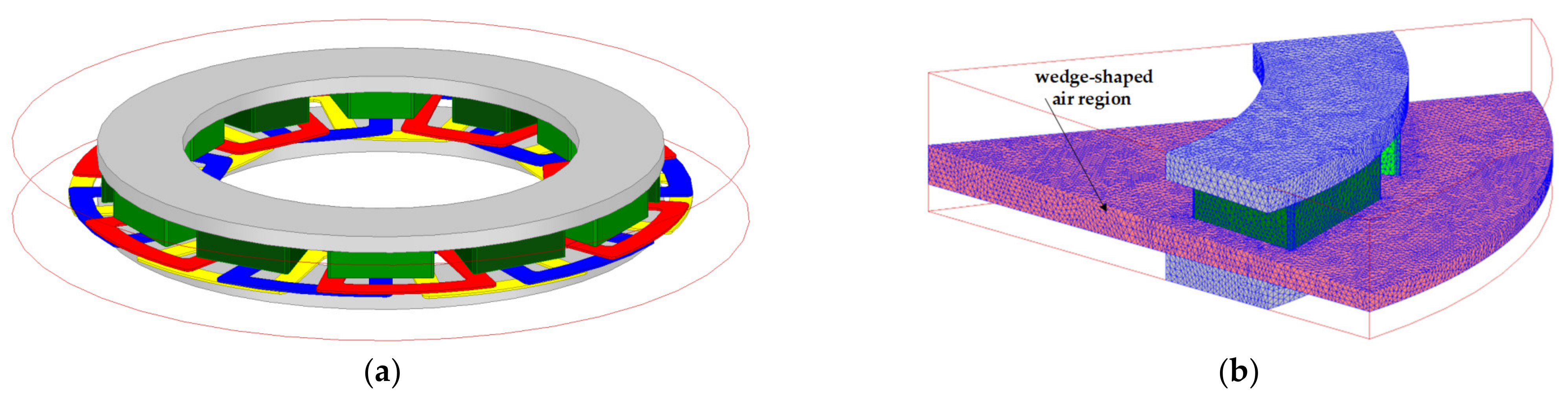
To verify the performance advantages of the coreless AFPM machine with the novel composite structure coils, in this section, the air gap flux density, no-load back EMF, and torque are analyzed by 3D FEA.

3.1. FEA Model

Figure 4a shows the 3D FEA model of the designed coreless AFPM machine. Since the field distribution of the AFPM machine is periodic, to simplify the calculation, the 3D element model can be constructed with detailed properties and meshed in FEA software, as shown in Figure 4b. The quality and number of meshes of the wedge-shaped air region are more precise and larger. In this paper, under the limited calculation conditions, the total number of mesh elements is 900 k to ensure the calculation accuracy as much as possible. The 3D FEA is calculated by a high-performance computing (HPC) workstation with two CPUs of 14 cores and 64 G memory.

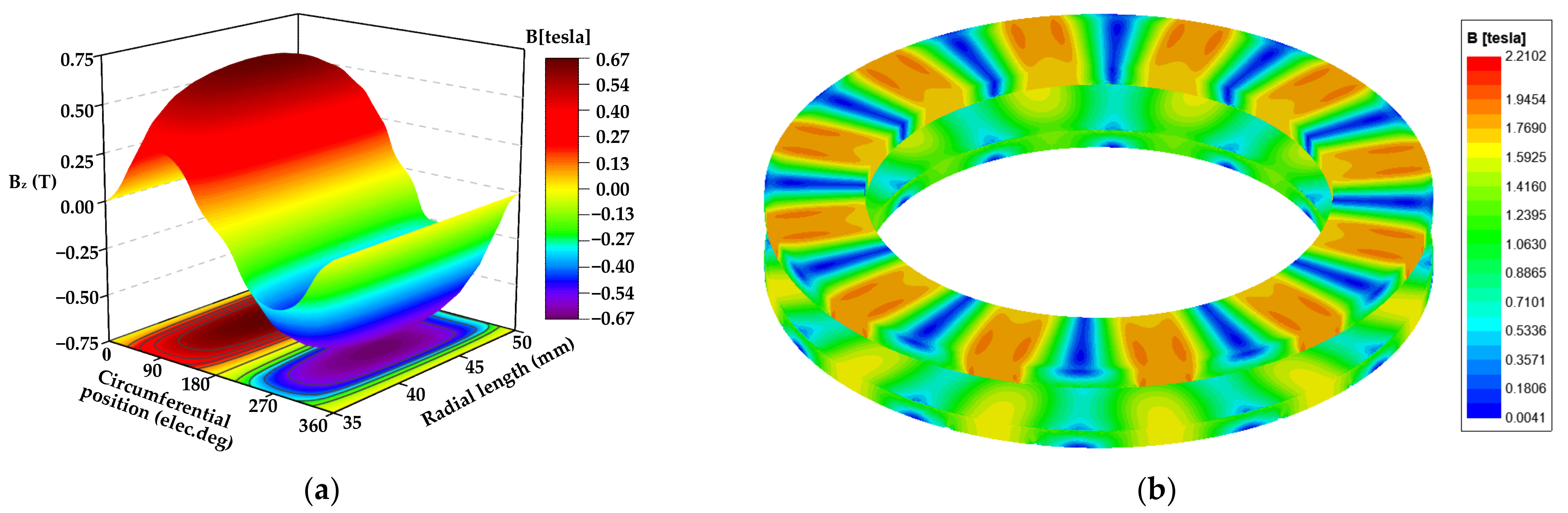
3.2. Air Gap Flux Density

The total air gap length of the coreless AFPM machine with double rotors and a single stator is related to the axial length of the coreless stator, which is the following:
h a = h s + 2 h p
where hp is the physical length of the air gap.
It is noted that the axial component Bz of air flux density contributes to inducing the back EMF and electromagnetic torque by the interaction with the current of effective conductors uniquely [9]. Considering the actual magnetic field distribution of the coreless AFPM machine is complex, 3D flux linkage and leakage flux paths cannot be ignored; the 3D FEA is particularly important for accurate calculation.
The air gap flux density distribution of the AFPM machine with an optimized coreless stator is analyzed at the mean axial length of the axial position of the air gap by FEA and illustrated in Figure 5a. The magnetic field distribution of rotor cores is also shown in Figure 5b.
Figure 6 shows the comparison of the axial component of the air gap flux density of two coreless stator structures at different circumferential and radial positions.
According to FEA results, the peak value of the air gap flux density of the AFPM machine with the optimized coreless stator is changed from 0.63 T to 0.67 T, which is an increase of 6.35%. The value of Bz is the highest at the average radial position, while the air gap flux density near the inner diameter and outer diameter of the rotor is less affected by the edge effect. The air gap flux density at the outer diameter location of the rotor is less than that at the inner diameter. The main reason is that the trapezoidal PMs are applied in this case, in which the outer diameter difference between the PMs and the rotor core is 0.8 mm. For the coreless AFPM machine with the optimized winding, the air gap flux density at the outer diameter of PMs is 0.37 T, which is 15.6% higher than that of 0.32 T at the inner diameter location and 8.8% higher than that of the original coreless stator. Therefore, it is verified that the optimized coreless stator can improve the air gap flux density a little by shortening the distance between double rotors, and further make the coreless AFPM machine obtain better performance when the number of PMs is the same.

3.3. No-Load Characteristics

For the AFPM machine, the axial flux per pole can be expressed as follows [21]:
ϕ = π 8 p α i B m D o 2 D i 2
where p is the number of pole pairs, αi is the effective pole arc coefficient that its value is 2/π when the waveform of air gap flux density is completely sinusoidal [9], Bm and Bav is the peak and average value of the air gap flux density.
The rms value of the no-load back EMF per phase is as follows:
E phase = 2 π f N 1 k w ϕ = 2 π n p 60 N 1 k w π 8 p α i B m D o 2 D i 2 = 2 π 2 480 n N 1 k w α i B m D o 2 D i 2
where f is the frequency, n is the rated speed, N1 = N/ma is the number of turns in series per phase, m is the number of phases, a is the number of parallel branches, and kw is the winding factor.
According to Equation (6), the no-load back EMF of the AFPM machine is directly related to the number of turns N and the air gap flux density B, both of which have been improved by using the novel composite structure coils. The waveform comparison of the no-load line back EMF between the original coreless stator and the optimized coreless stator is shown in Figure 7. It can be seen that the RMS value of the no-load line back EMF of the coreless AFPM with the novel optimized coils is increased to 30.97 V from 14.62 V at the rated speed of 3000 r/min by the increase in the turns and air flux density.
Figure 8 shows the harmonic decomposition result of the no-load line back EMF of the AFPM machine with these two types of coreless stator. The harmonic distortion rates of the machine with the original coreless stator and the optimized coreless stator are 5.3% and 5.86%, respectively. The most significant difference between the stators with the original and novel coils is still the amplitude value of the fundamental wave of back EMF.

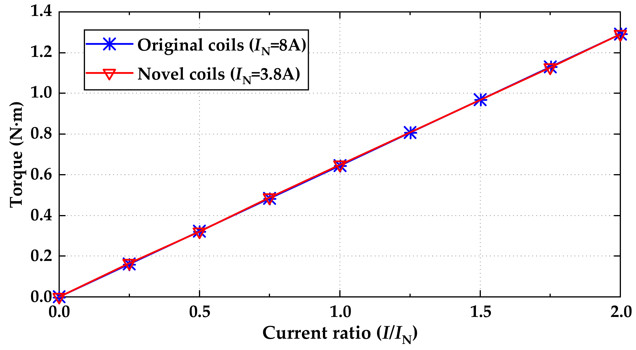
3.4. Load Characteristics

When the waveform of phase current is completely sinusoidal and the AFPM machine is operated at the rated condition, the torque of the machine can be expressed as follows:
T = m 2 p N 1 k w ϕ I m = m 2 p N m a k w π 8 p α i B m D o 2 D i 2 I m = 2 π 16 a N k w α i B m D o 2 D i 2 I N
where Im is the amplitude of phase current, and IN is the RMS value of the rated phase current. Because of the variation of turns and air gap flux density, the rated phase current of the AFPM machine with the novel coreless stator has been modified to generate the same rated torque such that the value of IN is 8 A for the coreless AFPM machine with the original coils and 3.8 A for the machine with the novel composite structure coils, as shown in Figure 9. Figure 10 shows that the relationship between the torque and phase current is linear because the inductance of windings is small and the influence of the stator current on the air gap flux density is almost negligible, which are the significant characteristics of the AFPM machine with a coreless stator.

4. Winding Loss and Efficiency
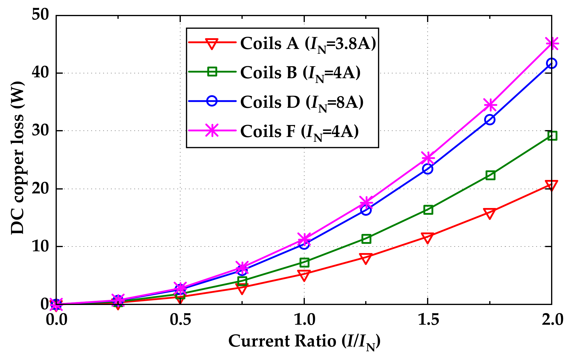
The main loss of the coreless AFPM machine is the winding loss from the stator. It is mainly related to the phase current and electric frequency, in which the former generates the DC copper loss and the latter generates the eddy current loss.

4.1. DC Copper Loss

The effect of varied temperature on the conductivity of conductors is ignored, and the expression of winding resistance per phase can be determined by the following:
R 1 = N 1 a ρ L S = N 1 a ρ 2 l S eff + l end S end
where ρ is the resistivity of the conductor, L is the length of the coil per turn, and S is the cross-sectional area of the coil per turn. For the AFPM machine with the designed coreless stator, l is the length of the single effective conductor, Seff is the cross-sectional area of the effective conductor, and lend and Send are the length and cross-sectional area of the end of the coil per turn, respectively.
The resistance results of windings with different structures and parameters are different under the same path. In this section, based on the position of the conductor in the entire coil, the resistance is divided into the resistance of the ends, the resistance of the effective conductors, and the resistance of the entire coils, as shown in Figure 11. The round wires C and E validate that the configuration at the inner diameter of the AFPM machine is saturated in Section 2.3. The resistance results of these two wire types are for reference only. These three resistance calculation results of effective sides, ends, and the entirety of the novel composite coils A are 0.0495 ohm, 0.0706 ohm, and 0.1201 ohm, respectively, compared with the normal rectangular coils B, which are reduced by about 6.6%, 28.69%, and 20.99%. The most significant difference between these two coil types is the resistance of their ends. Although the phase resistance of the original coreless AFPM machine with coils D is 0.0543 ohm, the number of turns N is only half of that of the machine with the novel coreless stator, which has been explained previously.
The DC copper loss is the main component of winding losses and the main source of temperature rise, especially when operated at a lower electric frequency, which is calculated according to the square of phase current, as follows:
P dc = m I 2 R 1
Figure 12 shows the DC copper loss of the coreless stator with different coil types under different phase currents. Obviously, the DC copper loss of coils A is less than that of coils B and F under the approximate phase current, which is 5.2 W at the rated state. The main loss difference between the rectangular coils B and the novel composite coils A is at the end of the windings. Meanwhile, compared to the original coils D, in which the turns are less, and the wire size is larger, the DC copper loss is reduced by 50% due to the difference in the designed rated current.

4.2. Eddy Current Loss

The eddy current loss of windings applied in the coreless AFPM machine is generated by exposure to the alternating air gap magnetic field, especially at a high frequency. The analytical expression for estimating the eddy current loss has been summarized in a large number of the literature. It is assumed that the waveform of air gap flux density is completely sinusoidal, and the eddy current loss of the coil ends is neglected; the eddy current loss can be expressed as follows [14,20]:
For round wires:
P eddy = π σ l N c N t N s ω 2 B m 2 d 4 128 = π 3 σ l N N s f 2 B m 2 d 4 16
For rectangular wires:
P eddy = σ l N c N t N s ω 2 B mz 2 w 2 + B mt 2 h 2 w h 24 = π 2 σ l N N s f 2 B mz 2 w 2 + B mt 2 h 2 w h 3
where σ is the conductivity of the conductor, Nc is the number of coil sides, Nt is the number of turns per coil, NcNt = 2 N, and Bmz and Bmt are the peak values of the axial and tangential components of the air gap flux density.
However, the summarized analytical method is only suitable for the initial fast design and optimization of the machine. In fact, the air gap flux density of the designed coreless AFPM machine in this paper is a trapezoidal wave, and there are a large number of harmonics in the magnetic field. In addition, the magnetic fields in the conductors at different positions in the coreless stator are different. In this paper, the more accurate eddy current loss estimation result is still calculated by the 3D FEA; the comparison of eddy current loss between the original and novel coils is shown in Figure 13. It can be seen that the average value of the eddy current loss of the coreless AFPM machine with the novel optimized coils is reduced to 4.75 W from 6.89 W at the rated speed of 3000 r/min, which is reduced by 31%. The reason for this decrease is that although the coil turns and air gap flux density of the AFPM machine with the novel coreless stator are increased as compared with the original motor, the parameters of the effective conductor are decreased, and the latter has a more significant influence on the eddy current loss of windings.

4.3. Efficiency

The significant loss of the designed machine is the winding loss, which consists of the DC copper loss and eddy current loss. Assuming that the other losses, such as the mechanical loss and stray loss, can be neglected, the efficiency of the coreless AFPM machine is expressed as follows:
P winding = P dc + P eddy
η = P out P out + P winding
where Pwinding is the total loss of windings and Pout is the output power.
Figure 14 shows the efficiency variation of these two types of coreless AFPM machines with different phase currents at the rated speed of 3000 r/min. It can be seen that the efficiency of the coreless AFPM machine with the original coils and the novel composite structure coils is 92.13% and 95.34%, respectively, under the rated condition. Both the DC copper loss and eddy current loss of windings are reduced, as previously verified; thus, the efficiency is finally improved by 3.21%. The efficiency advantages of the coreless AFPM machine with the novel composite structure coils are fully verified in this section.

5. Conclusions

The high-efficiency AFPM machine, which is applied to the electric bicycle, can not only save the energy of lithium batteries but also reduce long-term operating costs. In this paper, a coreless stator with the novel composite structure coils is proposed, in which each effective side of coils is reshaped from the round wire to the wedge-shaped wire by the rolling technology, while the ends of coils are kept in the cylinder with a larger diameter. According to this valuable optimization, both the electromagnetic performance and efficiency of the machine can be improved. The number of turns of coils and the filling factor can be increased due to the variety of effective conductor cross-sections. The designed and optimized coils are compared with several typical wire types, and the filling factors are 99.5% at the inner cross-section and 96.3% at the outer diameter cross-section. Both of which are close to the same and the effective electromagnetic space of the stator region is fully utilized. Moreover, the air gap length of the AFPM machine, especially located at the outer diameter, is further shortened by the structure optimization of coils, resulting in the air gap flux density of the machine being increased by 6.35%. Accordingly, several relevant output performances, such as the load torque and no-load back EMF, can be further calculated and analyzed with the 3D FEA simulation. Finally, the phase resistance of various feasible coils is calculated by the analytical method and discussed, and the proposed one is 0.1201 ohm. The research results indicate that the DC copper loss and eddy current loss can be reduced by 50% and 31%, respectively, under the rated operating condition. The coreless AFPM machine with the novel composite structure coils performs at a high efficiency of 95.34%, which is 3.21% higher than the original one. Therefore, the advantages of optimized windings are verified, which can offer reference value for the design of the coreless AFPM machine.
In future work, the eddy current loss of windings at a higher speed and the improvement of the inflexibility of conductors by rolling technology will be studied.

Author Contributions

Conceptualization, X.W. and X.C.; methodology, X.W.; software, T.L. and X.Z.; validation, T.L. and X.Z.; formal analysis, T.L.; data curation, T.L.; writing—original draft preparation, T.L.; writing—review and editing, T.L.; supervision, X.W. and X.Z. All authors have read and agreed to the published version of the manuscript.

Funding

This research received no external funding.

Institutional Review Board Statement

Not applicable.

Informed Consent Statement

Not applicable.

Data Availability Statement

Not applicable.

Conflicts of Interest

The authors declare no conflict of interest.

References

  1. Wang, C.; Han, J.; Zhang, Z.; Hua, Y.; Gao, H. Design and optimization analysis of coreless stator axial-flux permanent magnet in-wheel motor for unmanned ground vehicle. IEEE Trans. Transp. Electrif. 2021, 8, 1053–1062. [Google Scholar] [CrossRef]
  2. Shariati, O.; Behnamfar, A.; Potter, B. An integrated elitist approach to the design of axial flux permanent magnet synchronous wind generators (AFPMWG). Energies 2022, 15, 3262. [Google Scholar] [CrossRef]
  3. Lee, J.-Y.; Lee, J.-H.; Nguyen, T.K. Axial-flux permanent-magnet generator design for hybrid electric propulsion drone applications. Energies 2021, 14, 8509. [Google Scholar] [CrossRef]
  4. Wang, R.J.; Kamper, M.J.; Van der Westhuizen, K.; Gieras, J.F. Optimal design of a coreless stator axial flux permanent-magnet generator. IEEE Trans. Magn. 2005, 41, 55–64. [Google Scholar] [CrossRef]
  5. Frank, Z.; Laksar, J. Analytical design of coreless axial-flux permanent magnet machine with planar coils. IEEE Trans. Energy Convers. 2021, 36, 2348–2357. [Google Scholar] [CrossRef]
  6. Taqavi, O.; Taghavi, N. Development of a mixed solution of maxwell’s equations and magnetic equivalent circuit for double-sided axial-flux permanent magnet machines. IEEE Trans. Magn. 2021, 57, 8104411. [Google Scholar] [CrossRef]
  7. Wang, W.; Zhou, S.; Mi, H.; Wen, Y.; Liu, H.; Zhang, G.; Guo, J. Sensitivity analysis and optimal design of a stator coreless axial flux permanent magnet synchronous generator. Sustainability 2019, 11, 1414. [Google Scholar] [CrossRef] [Green Version]
  8. Tokgöz, F.; Çakal, G.; Keysan, O. Design and implementation of an optimized printed circuit board axial-flux permanent magnet machine. In Proceedings of the 2020 International Conference on Electrical Machines (ICEM), Gothenburg, Sweden, 23–26 August 2020. [Google Scholar]
  9. Geng, W.; Zhang, Z. Analysis and implementation of new ironless stator axial-flux permanent magnet machine with concentrated nonoverlapping windings. IEEE Trans. Energy Convers. 2018, 33, 1274–1284. [Google Scholar] [CrossRef]
  10. Fei, W.; Luk, P.C.K.; Jinupun, K. Design and analysis of high-speed coreless axial flux permanent magnet generator with circular magnets and coils. IET Electr. Power Appl. 2010, 4, 739–747. [Google Scholar] [CrossRef] [Green Version]
  11. Wang, X.Y.; Du, J.J. Performance analysis of a wedgy airgap disk coreless permanent magnet synchronous motor. In Proceedings of the 2006 IEEE International Conference on Mechatronics and Automation (ICMA), Luoyang, China, 25–28 June 2006. [Google Scholar]
  12. Huang, C.; Kou, B.; Zhao, X.; Niu, X.; Zhang, L. Multi-objective optimization design of a stator coreless multidisc axial flux permanent magnet motor. Energies 2022, 15, 4810. [Google Scholar] [CrossRef]
  13. Wang, X.Y.; Li, X.; Li, C.P.; Xu, S.J.; Ling, L.T. Design of a PCB stator coreless axial flux permanent magnet synchronous motor based on a novel topology Halbach array. Front. Inf. Technol. Electron. Eng. 2019, 20, 414–424. [Google Scholar] [CrossRef]
  14. Taran, N.; Rallabandi, V.; Ionel, D.M.; Heins, G.; Patterson, D. A comparative study of methods for calculating AC winding losses in permanent magnet machines. In Proceedings of the 2019 IEEE International Electric Machines and Drives Conference (IEMDC), San Diego, CA, USA, 12–15 May 2019. [Google Scholar]
  15. Tsai, M.C.; Hsu, L.Y. Design of a miniature axial-flux spindle motor with rhomboidal PCB winding. IEEE Trans. Magn. 2006, 42, 3488–3490. [Google Scholar] [CrossRef]
  16. Wang, X.Y.; Pang, W.; Gao, P.; Zhao, X.X. Electromagnetic design and analysis of axial flux permanent magnet generator with unequal-width PCB winding. IEEE Access 2019, 7, 164696–164707. [Google Scholar] [CrossRef]
  17. Shin, D.-Y.; Jung, M.-J.; Lee, K.-B.; Lee, K.-D.; Kim, W.-H. A study on the improvement of torque density of an axial slot-less flux permanent magnet synchronous motor for collaborative robot. Energies 2022, 15, 3464. [Google Scholar] [CrossRef]
  18. Wang, X.Y.; Lu, H.D.; Li, X. Winding design and analysis for a disc-type permanent-magnet synchronous motor with a PCB stator. Energies 2018, 11, 3383. [Google Scholar] [CrossRef] [Green Version]
  19. Andriollo, M.; Tortella, A. Preliminary design of an axial flux machine with coreless stator for flywheel applications. In Proceedings of the 2018 XIII International Conference on Electrical Machines (ICEM), Alexandroupoli, Greece, 3–6 September 2018. [Google Scholar]
  20. Kesgin, M.G.; Han, P.; Taran, N.; Lawhorn, D.; Lewis, D.; Ionel, D.M. Design optimization of coreless axial-flux PM machines with Litz wire and PCB stator windings. In Proceedings of the 2020 IEEE Energy Conversion Congress and Exposition (ECCE), Detroit, MI, USA, 11–15 October 2020. [Google Scholar]
  21. Tang, R.Y. Morden Permanent Magnet Machines Theory and Design; China Machine Press: Beijing, China, 1997; pp. 315–317. [Google Scholar]
Figure 1. Basic structure of proposed AFPM machine with a coreless stator: (1) stator armature; (2) shell; (3) bearing; (4) rotor core; (5) PMs; (6) reinforcement sheet; (7) stator support.
Energies 15 05162 g001
Figure 2. (a) Original coils; (b) optimized coils; (c) different wire types: (1) round conductor; (2) rectangular conductor; (3) wedge-shaped conductor.
Energies 15 05162 g002
Figure 3. Distribution of effective conductors: (a) round conductors; (b) wedge-shaped conductors.
Energies 15 05162 g003
Figure 4. (a) 3D FEA model of designed AFPM machine with coreless stator; (b) Meshes of rotors and wedge-shaped air region.
Energies 15 05162 g004
Figure 5. (a) 3D no-load air gap flux density distribution by FEA; (b) magnetic flux density distribution of the AFPM machine.
Energies 15 05162 g005
Figure 6. Axial component of the air gap flux density: (a) at different circumferential positions; (b) at different radial length.
Energies 15 05162 g006
Figure 7. Comparison of no-load line back EMF of the coreless stator with different coils.
Energies 15 05162 g007
Figure 8. Harmonic decomposition results of the no-load line back EMF.
Energies 15 05162 g008
Figure 9. Rated torque of the machine with different coreless stator.
Energies 15 05162 g009
Figure 10. Torque variation with different phase current.
Energies 15 05162 g010
Figure 11. Resistance distribution results with different wire types.
Energies 15 05162 g011
Figure 12. DC copper loss of coreless stator with different coil types under different phase current.
Energies 15 05162 g012
Figure 13. Comparison of eddy current loss between the original and novel coils.
Energies 15 05162 g013
Figure 14. Efficiency variation with different current.
Energies 15 05162 g014
Table 1. Fundamental parameters of coreless AFPM machine.
ParameterValue
Rated output power200 W
Rated speed3000 r/min
Torque0.64 N·m
Number of poles12
Outer diameter of rotor100 mm
Inner diameter of rotor70 mm
Physical length of air gap0.3 mm
Radial length of PMs14.2 mm
Axial length of PMs5 mm
Axial length of rotor core3 mm
Table 2. Calculation results of filling factor of different effective conductors.
TypeStructureWire Parameters (mm)hs (mm)NNsζiζo
AWedge0.76 × 1.25 (w1 × h1); 1.05 × 1 (w2 × h2)2.5 (hsi); 2 (hso)28810.9950.963
BRectangle0.76 × 1.25 (w × h)2.528810.9950.697
CRound1.32.628811.3370.936
DRound1.32.614410.6690.468
ERound1.252.528811.2860.9
FRound0.6252.528820.6430.45
Table 3. Original and optimized parameters of the coreless stator.
ParameterOriginal StatorFinal Optimized Design
Total number of turns144288
Axial length of stator2.6 mm2.5 mm (inner)/2 mm (outer)
Distance between double rotors3.2 mm3.1 mm (inner)/2.6 mm (outer)
Structure of effective conductorsroundwedge-shaped
Parameters of effective conductor1.3 mm0.76 mm × 1.25 mm (w1 × h1)/1.05 mm × 1 mm (w2 × h2)
Structure of endsroundround
Parameters of ends1.3 mm1.3 mm
Rated current8 A3.8 A
Publisher’s Note: MDPI stays neutral with regard to jurisdictional claims in published maps and institutional affiliations.

