Abstract
With the increasing proportion of wind turbines in power grids, they are required to have capabilities of active and efficient virtual inertial response to maintain grid frequency stability. However, the virtual inertial control methods currently used in doubly-fed induction generator (DFIG) units suffer from a secondary frequency drop (SFD) problem. Although the SFD can be inhibited by reducing the active power support strength of the DFIG units during inertia response, it will undoubtedly weaken the virtual inertia of the units. Therefore, how to eliminate the SFD while increasing the virtual inertia of the units is a worthy issue for studying. To solve this issue, a wind-storage combined virtual inertial control system based on quantization and regulation decoupling of active power increments is proposed in this paper. First, by setting the parameters of a proportional–differential (P-D) algorithm, the total active power increments required for virtual inertial response are quantified at the DFIG level. Secondly, a curve-shifting method based on the rate of change of frequency is adopted to adjust the active power output of the DFIG units. Finally, a battery energy storage system (BESS) is used to compensate for the power shortages of the units according to the quantized value of the active power increments. Simulations show that the control method can not only eliminate SFD but also effectively increase the system’s virtual inertia.
1. Introduction
China’s proposed ‘carbon peaking and carbon neutrality’ goals require the proportion of renewable energy in its power supply to be rapidly increased [1]. Common wind turbines, such as doubly-fed induction generators (DFIG) and permanent magnet synchronous generators, equip power electronic converter devices, which help to improve the utilization of wind resources. However, such converters decouple the wind turbine’s rotor speed from the grid frequency, causing its inertia to be ‘hidden’, which decreases the inertia of the grid [2]. This hinders the healthy and orderly development of new energy power grids [3]. In engineering applications, especially in China, DFIG occupies a higher proportion than other wind turbine types in the grids [4]. Therefore, it is imperative to study the virtual inertial control method of DFIG units with active and efficient frequency response characteristics to cope with the continuous increases in wind power penetration into the grid.
For this reason, a large number of studies have added a proportional–differential (P-D) module to the maximum power point tracking (MPPT) control link of a DFIG unit so that the kinetic energy of the rotor can be released/absorbed to provide additional active power support. The P-D algorithm adjusts the active power of DFIG units during frequency regulation according to grid-side frequency deviation and rate of change of frequency (RoCoF). This is one of the most widely used virtual inertial control methods for wind turbines [5]. However, the kinetic energy of the rotors in DFIG units varies greatly according to wind speed. Excessive utilization of the rotor’s kinetic energy may cause an over-limit of rotor speed that causes the generator to cut off [6]. Moreover, the P-D algorithm makes the rotor speed and electromagnetic power of the unit deviate from the MPPT curve during the frequency regulation, which is highly random and uncontrollable, such that secondary frequency drop (SFD) can easily occur when the rotor speed is restored [7]. Therefore, although the P-D algorithm makes the DFIG units capable of having an active response to frequency disturbance, it harms the frequency stability if the rotor kinetic energy is excessively consumed. In response to this issue, many studies have alleviated the SFD or avoided cut-off accidents by optimizing parameters of the P-D algorithm. In studies [8,9], the trial-and-error method was used to fit differential and proportional parameter curves, so that the parameters of the P-D algorithm could be adjusted according to wind speed, ensuring that rotor speed fluctuations of the unit remain within a safe range. In another study [10], BANG-BANG control was used to optimize the P-D parameters so that the unit’s active output changes at different stages of the frequency regulation, which is beneficial to the rapid recovery of rotor speed and suppresses the SFD. Reference [11] used a fuzzy algorithm to assign 0–1 weights of the defined ‘maximum virtual inertia time constant’ according to the typical frequency variation and obtained the differential coefficient of the P-D algorithm with adaptive characteristics. Considering the influences on active power output caused by wind power capture losses, the concept of the ‘net inertia time constant’ was proposed in [12] to set the parameters of the P-D algorithm. This can effectively alleviate the SFD phenomenon. Study [13] adjusted P-D coefficients of two stages of deviation and recovery during frequency regulation, respectively, via analysis of the zero-pole distribution, so that the output of the DFIG units was constrained to a given stability domain. These studies have effectively inhibited the SFD or turbine’s cut-off via adjusting the proportional and differential coefficients of the P-D algorithm. However, to achieve this purpose, the above methods reduce the active power support strength of the DFIG unit in inertia response, resulting in a further decrease in the frequency nadir [14].
Similarly, to inhibit the SFD, some researchers have abandoned the P-D algorithm using, for example, fuzzy logic controller [15], fast frequency control (FFR) [16], etc. Although these methods can effectively suppress the SFD through the tuning of control parameters, they still cannot prevent the rotor speed and electromagnetic power from deviating from the power tracking curve, which can easily lead to the mutual influence between the additional power and the reference power of the wind turbine. Therefore, the active output of the unit must be limited. In other studies [17,18,19], a virtual inertial control based on the curve-shifting method was proposed. The method ‘shifts’ the power tracking curve by changing the curve coefficient to vary the active power output and restrain SFD. Compared to others, the curve-shifting method makes the electromagnetic power of the unit and its rotor speed always follow the power tracking curve during the process. The two are coupled and controllable, which effectively avoids the inherent defects of the above methods. Nevertheless, according to the simulation results in the above literature, the method also exhibits the following shortcomings. First, the curve-shifting method changes the coefficient of power tracking curve according to the frequency deviation, so the inertial response speed is far less than that of the P-D algorithm, which needs to be further improved. Second, the magnitude of the active power increments for virtual inertia response is determined by the range of variation of the power tracking curve; it limits increases in the active power. Therefore, no matter what existing method is adopted, there is a conflict between suppressing SFD and increasing the strength of active power support. It is difficult to achieve both at the same time. This is mainly due to the peculiar electromechanical transient characteristics of DFIG units and the lack of reserve capacity for the frequency event in MPPT mode [20].
Along with the rapid progress in energy storage technology and its large-scale application, using energy storage to assist in frequency regulation can significantly increase the reserve capacity of DFIG units. Studies [21,22] employed a battery energy storage system (BESS) and a compressed air energy storage device, respectively, to compensate for the wind energy losses when the unit participates in frequency regulation, so as to support the rotor speed recovery of the unit. In other studies [23,24], FFR was used for the virtual inertial control of DFIG units. The energy storage intervenes at the stage of rotor speed recovery to compensate for the de-loading active power of FFR, thereby alleviating the sudden drop in active power for response. These studies only suppressed the SFD during rotor speed recovery with the assistance of energy storage but did not discuss how to control energy storage to enhance the support strength of active power in inertial response. In studies [25,26], the DFIG unit and BESS were responsible for the active power increments determined by the inertial and drooping parts of the P-D algorithm, respectively, so that the energy storage system could participate in frequency regulation throughout the whole process. This can increase the active power supplied by the inertial response; however, the coordination between wind and storage power is poor when the virtual inertia of the wind-storage system is not quantified. In view of this, the methods of model prediction and fuzzy logic control were adopted in [27,28], respectively. Firstly, the virtual inertia is quantified at the wind farm level or system level, then the active output of the unit and BESS are distributed secondarily. Due to pre-quantization of the active power increment providing a standard measure for the wind-storage total output, the wind–storage coordination mechanism becomes more reasonable. This is very important for coordinating wind turbines and energy storage for frequency regulation and has reference significance for the control method in this paper. However, current quantification methods are mostly based at the wind farm or grid levels, while the frequency-regulated capability of single DFIG units has not been fully considered [29]. This leads to inaccurate quantification of the active power required for frequency regulation, preventing significant enhancements to the virtual inertia of wind-storage systems.
To sum up, this paper proposes a virtual inertial control method for wind-storage systems based on quantization and regulation decoupling of active power increments. It aims to overcome the conflict between suppressing SFD and increasing the strength of active power support, to achieve co-improvement of them. On the basis of quantization and regulation decoupling of active power increments, various virtual inertial control methods are combined in the proposed method. Firstly, the P-D algorithm is used to accurately quantify the total virtual inertia of the wind-storage system at the DFIG level. Secondly, the RoCoF-based curve-shifting method is used to adjust the active power output of the DFIG. Thirdly, a BESS is used to compensate for the shortages in the active power of the DFIG so that the wind turbine and BESS can provide the required quantized power in a coordinated manner.
2. Decoupled Control of Quantization and Regulation of the Active Power Increments
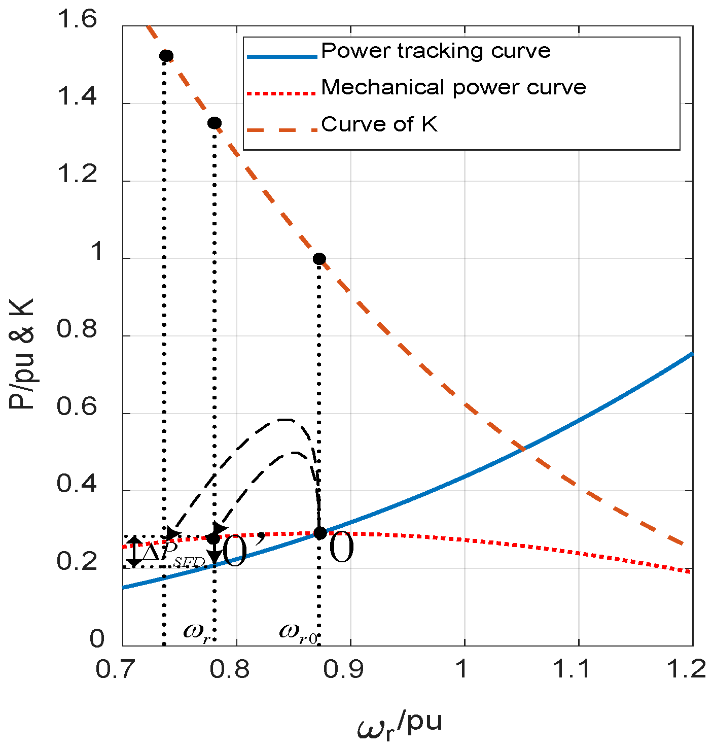
When there is no reserve power, DFIG units rely on the rotor’s kinetic energy to participate in frequency regulation. As in a synchronous generator (SG), the energy ΔE released by the rotating mechanism of the unit satisfies Equation (1), where J is the moment of inertia of the unit, and ωr0 and ωr are the initial speed and real-time speed of the rotor, respectively. It can be known that the greater the variation in rotor speed, the stronger the energy support. However, unlike an SG, the electromagnetic power output of a DFIG unit follows the MPPT curve. As the rotor speed slows down, the active power reference value will decrease, as shown in Figure 1.
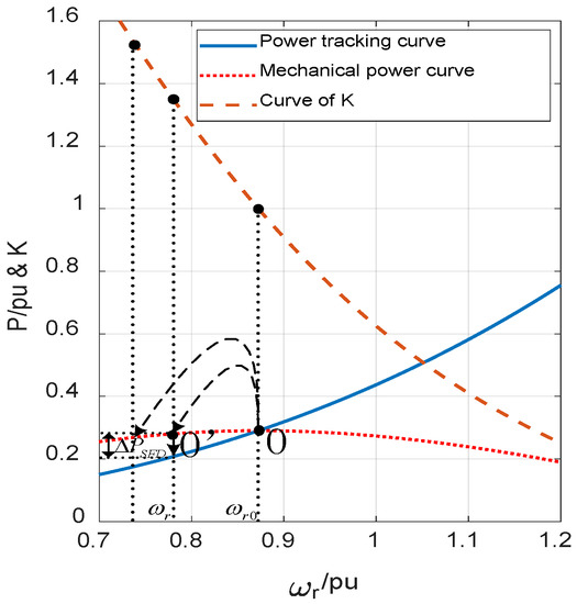
Figure 1.
Relationships of mutual restriction between stability and support strength of frequency-regulated active power.
In the figure, the mechanical power curve Pm and power tracking curve Pe of the DFIG unit satisfy Equations (2) and (3), respectively, where ρ represents the air density, S and R are the rotor blades swept area, and its radius, Cp and Cpmax are the real-time and maximum values of the wind energy utilization coefficient, and λ and λopt are the real-time and optimal values of the tip speed ratio, respectively. The ratio between the mechanical and electromagnetic power of the unit is defined as the electromechanical deviation coefficient K, which is a function of ωr, as shown in Equation (4) and the K-curve in Figure 1. The DFIG unit operates at point O in the figure in a steady state. From the rotor motion equation (Equation (5)), it can be known that when a unit participates in frequency regulation using the rotor kinetic energy, the stronger the active power support, the greater the drop in rotor speed amplitude, and the K is larger. This means that the gap between Pm and Pe increases with decreasing rotational speed. When the operating point reaches point O’ via the virtual inertial response, the rotor speed starts to recover. Here, ΔP in Equation (5) turns positive to negative, and the unit absorbs power from the grid instead. The active output of the unit drops rapidly, and a power deficit of size ΔPSFD is generated instantaneously in the grid, thus causing the SFD phenomenon. To alleviate this phenomenon, the K-coefficient must be reduced by suppressing the electromagnetic power output of the DFIG unit; however, this will lead to a weakening of the virtual inertia, and vice versa.
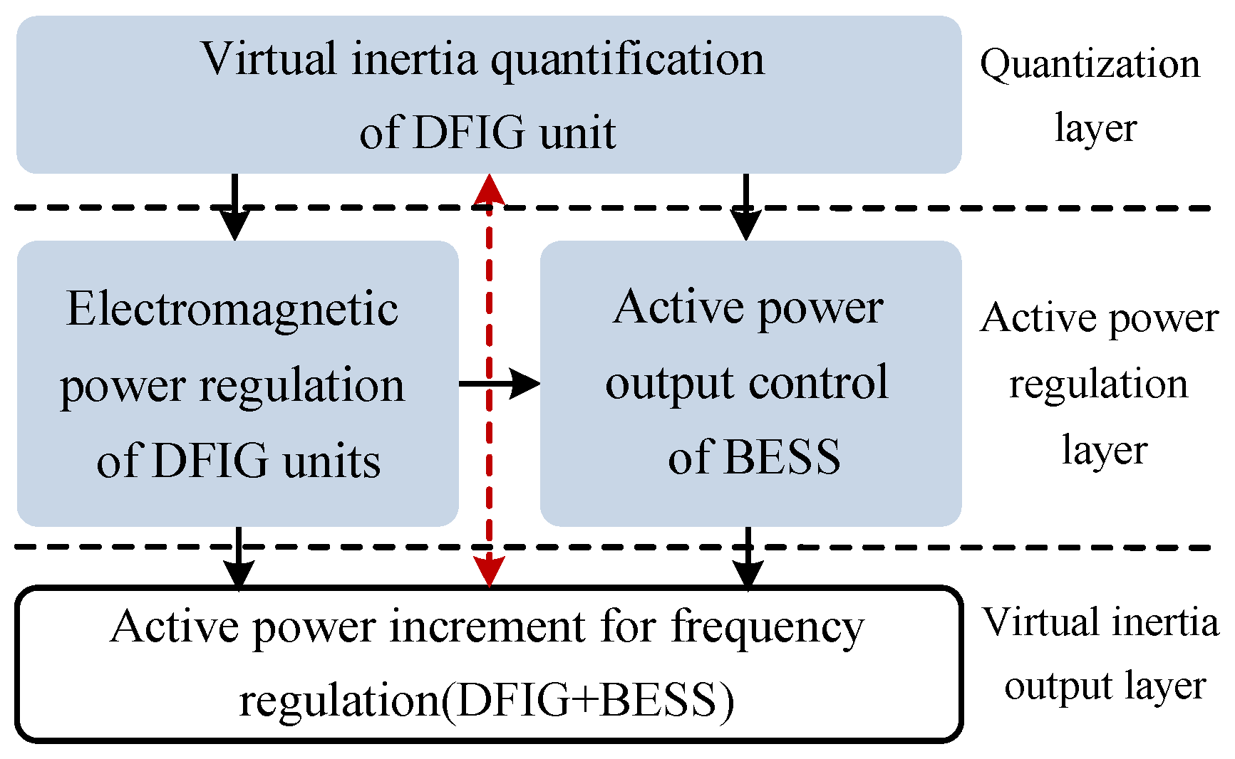
Therefore, a virtual inertial control system based on quantization and regulation decoupling of active power increments is proposed (Figure 2). For decoupling, the quantization layer only needs to quantify the releasable active power increments according to the operating conditions of the DFIG unit; that is, its virtual inertia. The SFD during rotor speed recovery can be ignored temporarily. In the active power regulation layer, the DFIG unit is considered an independent frequency-regulated source, and the suppression of SFD and the improvement of the inertial response speed are the main considerations. Moreover, the BESS compensates for the active power shortage of the unit according to the output result from the quantization layer, so that the unit and BESS can achieve the quantization value together at the output layer of virtual inertia.
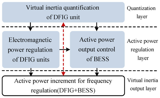
Figure 2.
Wind-storage combined virtual inertial control topology based on quantization and regulation decoupling of active power increments.
3. Quantization of Virtual Inertia at the DFIG Level
To improve the support strength of the active power for the virtual inertial response, this section studies a virtual inertia quantization method at the DFIG level. The principle is to maximize the use of the rotor’s kinetic energy.
Considering the orderly synchronization of frequency-regulated power between the DFIG units and the SG units in the grid, the quantification method needs to be determined according to the inertial response characteristics of the SG units. Equation (6) expresses the inertial response principle of an SG unit [30,31], where ΔTe, Tm, and Te are the electromagnetic torque increment, mechanical torque, and electromagnetic torque of the SG, respectively, and Hg represents the inertial time constant, f is the system frequency, ΔPe is the electromagnetic power increment, and superscript * indicates the per-unit value. Methods for controlling the virtual inertia of DFIG units include the P-D algorithm, curve-shifting method, and FFR; among these, the frequency regulation characteristics of the P-D algorithm are most similar to those of SG units, as shown by Equation (7) [32]. However, the inertia coefficient kdf and the droop coefficient kpf of the traditional P-D algorithm are usually fixed and cannot follow the wind speed or different frequency-regulated stages to produce changes. Therefore, to ensure the accuracy of the quantization method, it is necessary to set the parameters of the P-D algorithm. It is worth mentioning that kdf and kpf are set for different purposes than in previous studies. In this paper, as we decouple the quantization and regulation of virtual inertia, the values set for kdf and kpf do not need to consider the change of active power in the stage of rotor speed recovery. The purpose of setting these parameters is to estimate the unit’s output according to its operating conditions and frequency variation.
3.1. Differential Coefficient Setting of the P-D Algorithm
As a result of the analysis in the previous section, the setting of the differential coefficient could convert into a calculation problem of the virtual inertia time constant. If the DFIG unit is treated as an SG unit during the frequency regulation and ignores the influence of the drive train, the rotor kinetic energy change is expressed as [33]:
where JDFIG is the inherent moment of inertia of the unit, and ωe and ωe0 are the dynamic and rated angular frequency of the grid, respectively, p represents the pole pairs of the generator. According to this, the virtual moment of inertia JV of the DFIG unit relative to the grid’s frequency variation deduces as
The virtual and inherent inertial time constants of the DFIG units express as per Equation (10). Where SN is the rated capacity of a DFIG unit. Substituting Equation (10) into Equation (9), and a detailed expression of the virtual inertia time constants can obtain, as shown in Equation (11). ωN is the rated rotor speed of the DFIG unit. However, it should be noted that the derivation of Equation (11) is based on the result of the change in the unit’s rotor speed and cannot reflect the dynamic process of the virtual inertial response. At the instant of the inertial response, because the rotor speed cannot change abruptly at this time, ωr ≈ ωr0, resulting in HV ≈ 0. Therefore, this leads to an incorrectly quantized result in the differential part.
For this reason, Equation (11) should be modified to consider the maximum utilization of the rotor’s kinetic energy. The kinetic energy will be completely consumed when the rotor speed reaches the limit, otherwise, it will cause the unit to cut off, so let ωr = ωmin (this paper takes ωmin = 0.7 pu). So far, − represents the effective support capability of the rotor kinetic energy of the DFIG unit at different steady-state rotor speeds; that is, different wind speeds. At the beginning of the power disturbance, as ωe ≈ ωe0, the parameter HV tends to infinity and the accuracy of the quantization results cannot be guaranteed. In engineering applications, the grid frequency is set within an allowable fluctuation range. When the frequency falls beyond the limit, an under-frequency load shedding (UFLS) protection device will cut off the load [34]. Therefore, let ωe0 = ωe_min, where ωe_min is the lower limit of the frequency allowed by the grid. In China, its range is usually 49.5–49.8 Hz. Finally, the modified virtual inertial time constant is obtained, as shown in Equation (12). The physical meaning of its expression is to release all the kinetic energy of the rotor within the allowable speed range and to limit the frequency nadir to more than the lower limit of the grid frequency. Replacing kdf with HVX can make the differential coefficient change dynamically according to the real-time wind speed and frequency. From the perspective of wind speed, the higher the wind speed, the greater the values of ωr0 and kdf. The DFIG unit has a strong ability for frequency regulation that can release higher rotor kinetic energy and vice versa. From the perspective of frequency dynamics, the difference between ωe and ωe_min is relatively large at the initial time of frequency regulation and the value of kdf is small; however, as the frequency deviation increases, kdf gradually increases. The closer the frequency drop is to ωe_min, the faster the change in kdf, to avoid the frequency nadir from exceeding the lower limit. Consequently, the differential component in active power increments can be accurately quantified by the setting of kdf.
3.2. Proportional Coefficient Setting of the P-D Algorithm
The proportional component imitates the droop characteristics of SG units. Unlike these units, there is no reserve capacity in MPPT mode for DFIG units. In this regard, to lay a foundation for the curve-shifting method introduced in Section 4 and future research into primary frequency regulation, we adopt rotor over-speed control to make the DFIG unit run in a de-loaded mode [35] at a de-loading ratio of d%. Over-speed de-loading not only allows the unit to retain its reserve capacity but also increases the kinetic energy stored in the rotor.
The proportional coefficient of the P-D algorithm corresponds to the unit-regulated power of the SG units. That is the increase in the active output of the unit when the grid frequency changes by 1 Hz. From this, the kpf setting method shown as Equation (13) is obtained, where Preserve is the de-loading power of the DFIG unit at a wind speed of v.
It can be seen that the value of kpf depends on the three variables d%, v and ωe. Among them, the unit’s ability to use the reserve capacity to participate in frequency regulation under the current operating conditions is reflected by d%, and v. Variable ωe dynamically adjusts the value of kpf according to the characteristics of frequency change. At the beginning of the inertial response, because the difference between ωe and ωe_min is large, the value of kpf is small, and the differential component of the quantization method plays a leading role in this period. As the frequency deviation becomes larger, the quantified weight of the proportional component gradually increases to satisfy the power-frequency demand of the primary frequency regulation of the power grid. Therefore, the quantization method of the proportional component accords to the dynamic process of power grid frequency regulation, which ensures the accuracy of the quantization results.
3.3. Quantification Model of Virtual Inertia at the DFIG Unit Level
To describe the quantization method intuitively, a quantification model of virtual inertia at the DFIG unit level is shown in Figure 3. A phase-locked loop (PLL) is employed to detect the grid-side frequency. When the frequency deviation exceeds the dead band, first judge whether the sign of Δf is positive or negative to provide a basis for the RoCoF limiter. According to the frequency-regulated principles in power grids, it is considered that when the RoCoF changes from positive or negative to 0, the virtual inertial response ends. Hence, a limiter with variable upper and lower limits is used to avoid disturbance of the active power controller caused by the positive and negative transition of the RoCoF during the process of frequency regulation. The values of its upper and lower limits are shown in Equation (14). Finally, a quantized result of size ΔPe is obtained by the methods described in Section 3.1 and Section 3.2. This is the reference value of the total virtual inertia of the wind-storage system.
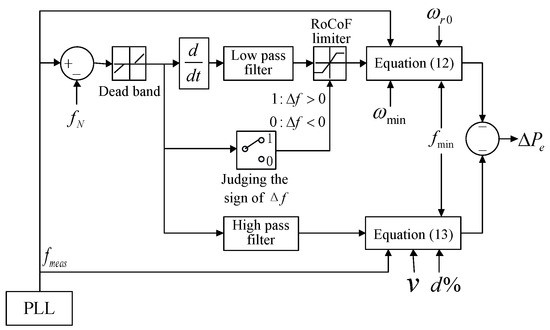
Figure 3.
Block diagram of quantization control for virtual inertia at the DFIG unit level.
It is worth noting that since the quantization and regulation of the active power increment are decoupling, the model only quantifies the virtual inertia of the active power support stage. The passive change in the active power output of the DFIG unit during the rotor speed recovery has not been considered yet. Therefore, on the basis that the virtual inertia is quantified, the curve-shifting method can be used to adjust the active power output of the unit in a virtual inertial response.
4. Regulation of the Active Power Output of DFIG Units Based on the Curve-Shifting Method
To effectively suppress the SFD during rotor speed recovery in DFIG units, a curve-shifting method based on the RoCoF is introduced, using it to provide virtual inertia of wind turbines.
4.1. Inertial Response Principle of the Traditional Curve-Shifting Method
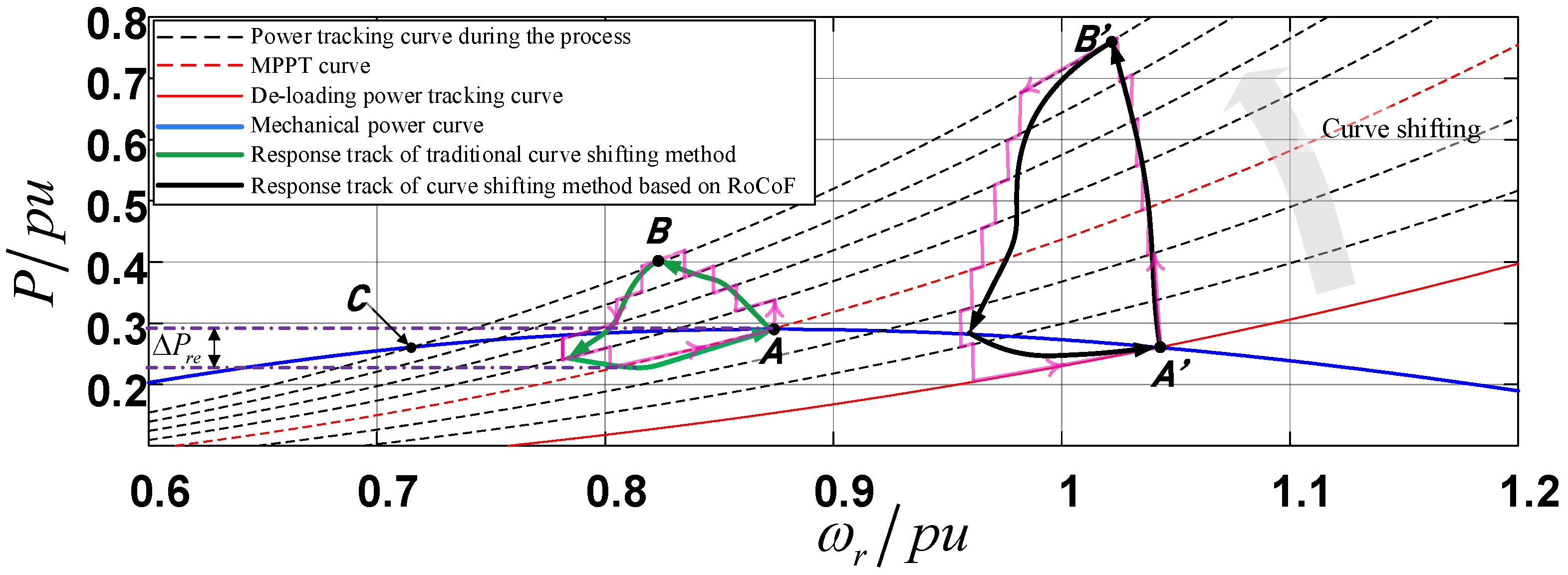
The power tracking curve described by Equation (3) can also be written as Equation (15). It can be seen that the curve can be ‘shifted’ by changing its coefficient kopt, to adjust the active power output of the DFIG unit [36]. As shown in Figure 4, the unit operates at point A in a steady-state in MPPT mode. When frequency disturbance occurs on the grid-side, the coefficient of the curve is recalculated according to the frequency deviation so that the MPPT curve is shifted. Since the rotor speed cannot change rapidly according to shifts in the MPPT curve, the electromagnetic power will gradually increase to point B with increases in frequency deviation to provide additional active power for the inertial response. For convenience of explanation, Figure 4 shows a finite number of power tracking curves during the process of frequency regulation. It allows detailed changes in the trajectories of electromagnetic power and rotor speed to be observed, which are showed as pink zigzag lines. As the density of the curve distribution increases, the response process of active power in the traditional curve-shifting method is equivalent to the green solid line in the figure. It can be seen that the curve-shifting method can make the electromagnetic power and rotor speed always follow the power tracking curves. Hence, the system robustness is enhanced by coupling these two factors. Moreover, in the stage of rotor speed recovery, the electromagnetic power is constrained by the dynamically adjusted tracking curve. Then, the speed recovery process is smoother, which avoids sudden drops in the active power output of the DFIG. Thus, the SFD phenomenon can be effectively alleviated or even eliminated by this method.
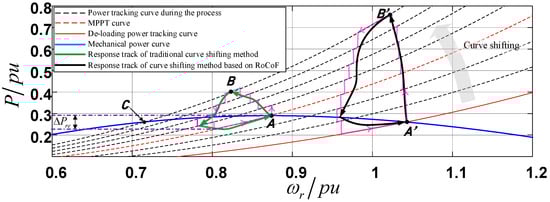
Figure 4.
Principle of virtual inertial response based on the curve-shifting method.
However, calculating the coefficient of the power tracking curve according to the grid-side frequency deviation will reduce the inertial response speed of the unit. The active power cannot be improved rapidly, which is not conducive to the suppression of RoCoF. In addition, the rotor speed recovers only when the electromagnetic power is less than the mechanical power according to the electromechanical transient characteristics of the generator. Then, the speed-recovery process will generate a negative power in the grid relative to the initial electromagnetic power due to the MPPT operation of the unit, as shown by ΔPre in the figure. It increases the frequency-regulated pressure of the SG units in the grid, which is likely to cause secondary fluctuations in active power. Therefore, de-loading by using rotor over-speed control can better improve the frequency-regulated effect with the curve-shifting method.
4.2. Calculation of the Power Tracking Curve Coefficient Based on RoCoF
Rotor over-speed control reduces the economics of wind farms’ operation to a certain extent, but it is conducive to the coordination and balance of active power between different generators during frequency regulation in the grid [37]. At the same time, the reserve capacity and rotor kinetic energy of the DFIG units are both increased. Nevertheless, the shifting range is limited, otherwise, it could cause the electromagnetic power or rotor speed to exceed the limit. Based on this, and to minimize negative power disturbances to the power grid caused by speed recovery, the range of power tracking curve shifting is delimited as follows.
At a constant wind speed, the mechanical power of the DFIG unit only depends on Cp by Equation (2). Thus, it can be deduced from Equation (15) that the coefficient of the power tracking curve when the unit’s de-loading ratio is d% expresses as
where Cpdel is the wind energy utilization coefficient under de-loading operation. According to the Cp-λ function relationship shown in Figure 5, the values of λ can be obtained by calculating the inverse function of Cpdel. Here, the value of λ is not unique because the curve is non-monotonic. The obtained values of λup and λdel can be substituted into Equation (16) separately to get the power tracking curve coefficients kup and kdel. Among them, kdel is the coefficient of the de-loading tracking curve, which is the lower limit of the tracking curve coefficient, and kup is the upper limit. We define the kup curve as the ultimate-limit power-tracking curve. It intersects with the Pm curve at point C in Figure 4, so this is the electromagnetic power symmetry point of point A on the curve plane. Thus, the shifting range of the power tracking curve is delimited between the de-loading tracking curve and the ultimate-limit power-tracking curve. In this way, not only the negative power disturbance to the power grid weakens, but the adjustable range of rotor speed is also expanded within a limit. On this basis, the method of calculating the power tracking curve coefficient based on RoCoF will be explored.
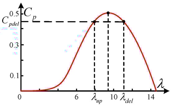
Figure 5.
Wind turbine Cp–λ curve.
To improve the inertial response speed of the curve-shifting method, the de-loading tracking curve should be ‘shifted’ rapidly at the moment of a power disturbance. The trajectories of change in rotor speed and active power are shown as black solid lines in Figure 4. Ignoring the slight change in rotor speed, it is considered that the electromagnetic power has a vertical upward trend. Assuming that the power disturbance is large, the tracking curve coefficient suddenly increases from kdel in a steady state to the maximum value kup, while the tracking point rises rapidly from A’ to B’, so the active power increments required for virtual inertial response expresses as:
Without loss of generality and real-time performance, kup is replaced by , and the initial speed ωr0 is replaced by the real-time speed. Based on the rotor motion equation, the active power increment of the DFIG unit can also be written as [38]:
Per-unitization of this equation yields Equation (19), and by substituting it into Equation (17), a method for calculating a RoCoF-based power-tracking curve coefficient is obtained (Equation (20)).
where Δωr is the increment of the unit’s rotor speed and Δωe is the deviation of synchronization angular frequency on the grid-side. γ is widely defined as the speed adjustment coefficient, and its value is generally selected according to the engineering application. It can be seen from Equation (20) that in the early stage of frequency regulation, due to the rapid decrease in RoCoF and ωr, k’ del will change rapidly to provide fast active power support. This increases the virtual inertia of the DFIG unit at the instant of inertial response. When the rotor speed begins to recover, the excessively fast callback of k’ del is restrained due to the increase in ωr, which further avoids the sudden drop in active power.
To sum up, a control block diagram of the RoCoF-based curve-shifting method is shown in Figure 6. By delimiting the shifting range of the power tracking curve and calculating the curve coefficient based on the RoCoF, the reference rotor speed of the DFIG unit can be obtained from Equation (21). The comparative error between and the real-time speed of the DFIG unit is converted to the active power reference Pe_ref by the PI regulator, which is input to the rotor-side converter (RSC) of the unit to control the active output. Here, Pe_m is the real-time active output by the unit. The control method proposed in this section not only retains the curve-shifting method’s advantages of stable active power during rotor speed recovery but also significantly improves the DFIG’s virtual inertial response speed compared with the traditional method. However, the RoCoF-based curve-shifting method may not be able to attain the quantization requirements of virtual inertia when the grid-side power disturbance is large, because the power tracking curve has a limited shifting range. Therefore, it is necessary to employ a BESS to provide more virtual inertia for the wind farms.
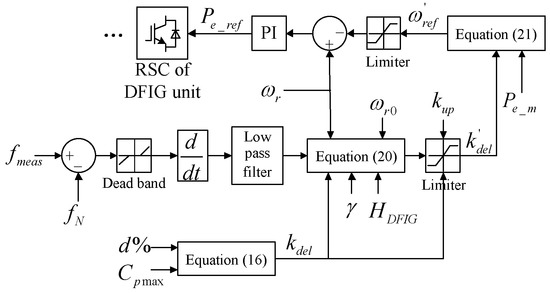
Figure 6.
Regulation of the active power output of DFIG units based on the curve-shifting method.
5. Active Power Control of a BESS
A BESS is usually consists of a battery stack and a power conversion system (PCS). Lithium-ion batteries are one of the most common battery types used in large-scale BESSs and have a rapid and flexible active power throughput capability. Their usefulness in frequency regulation has been widely confirmed [39]. Based on the control model presented in Section 3 and Section 4, this section uses a lithium-ion BESS to compensate for the active power shortage of the DFIG unit during frequency regulation in real-time according to the quantized virtual inertia. This is expressed as Equation (22), where, PBESS_in represents the shortage in the unit’s active power, that is, the active power input command of the BESS, Pe_DFIG is the real-time active output of the unit during frequency regulation, Pe0_DFIG is its active power output in steady-state, and ε is the power conversion factor of the BESS relative to the DFIG unit in per-unit form.
Lithium-ion batteries have little change in port voltage within a state-of-charge (SOC) range of 15–85% [40]. In view of this, to let the active power output of the BESS follow the command quickly and accurately, a single-stage power-frequency isolated PCS is assembled for the battery stack. The basic structure of the BESS is shown in Figure 7. The PCS completes the AC-DC conversion and four-quadrant adjustment of the battery power via control of the DC/AC converter, which is based on a three-phase fully-controlled bridge circuit and uses IGBTs as switches. The electrical separation between the systems is realized by the isolation transformer. This kind of PCS has a simple structure and high response speed, making it suitable for rapid power output for inertial frequency regulation.
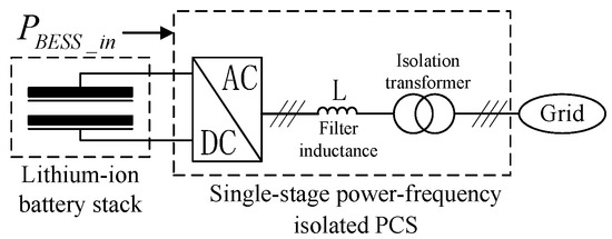
Figure 7.
BESS structure based on a single-stage power-frequency isolated PCS.
In Figure 7, the relationship between the grid voltage and PCS outlet voltage satisfies Equation (23), where, Uabc and Eabc are the three-phase voltage vectors on the outlet side of the converter and grid side, respectively, and Iabc is the three-phase current vector on the grid. Here, the grid-voltage-oriented vector control is adopted. After the phase angle of the grid’s voltage is detected by the PLL, the three-phase stationary coordinate system is converted to a two-phase rotating coordinate system through PARK transformation. Hence, Equation (23) can be written as:
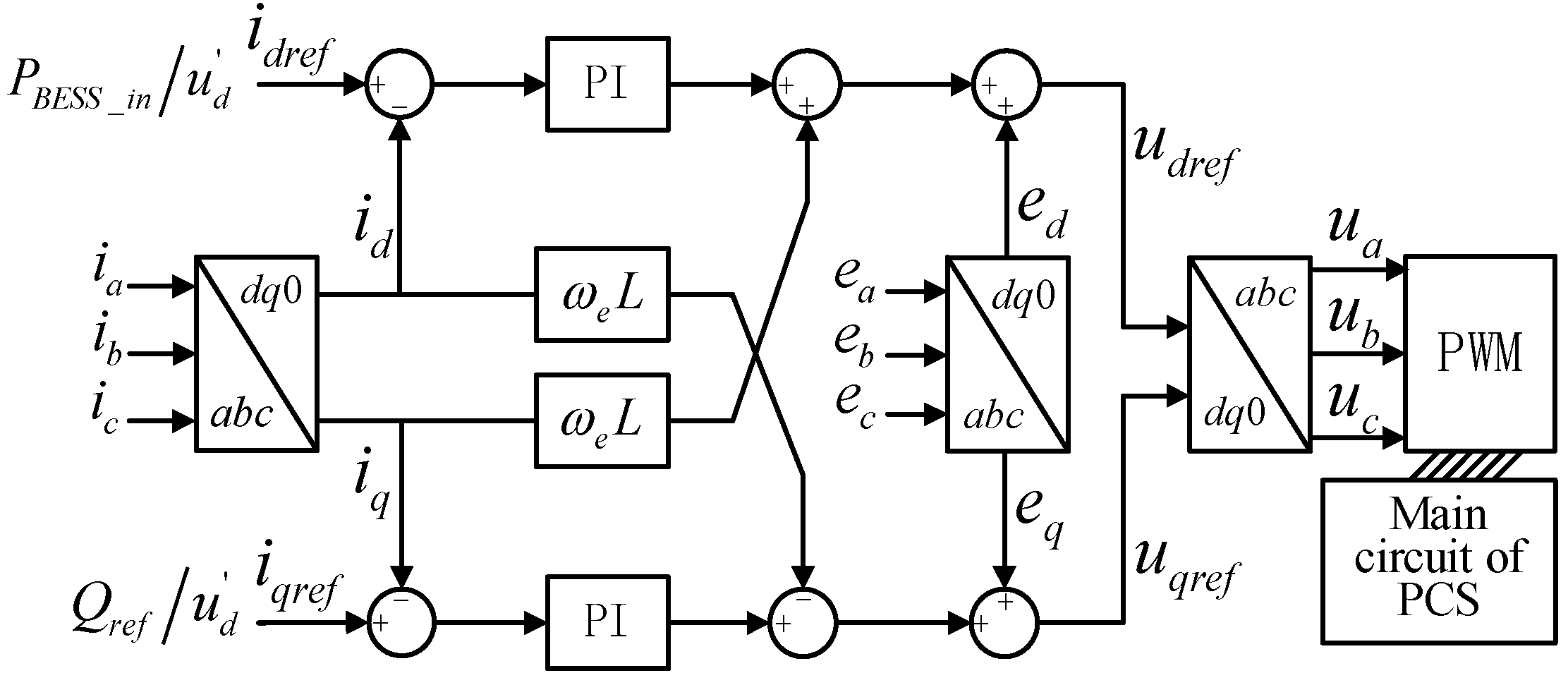
where L is the filter inductance of the PCS, u is the converter’s outlet-voltage vector, e is the grid-voltage vector, i is the current vector, and subscripts q and d represent the active and reactive components under the two-phase rotating coordinate system, respectively. Based on this, the PCS power control model is finally established after pre-processing the power command and adding a feedforward decoupling link to the current loop, as shown in Figure 8, where u’ d is a constant equal to the peak grid-side phase voltage. The reference value idref of the active component of the current can be obtained through command pre-processing. The reference value udref of the voltage vector at the outlet side of the converter can be determined according to Equation (24) with the PI regulator. After that, the reference value of the voltage in the three-phase stationary coordinate system is obtained by PARK inverse transformation to control the on-off status of the tubes.
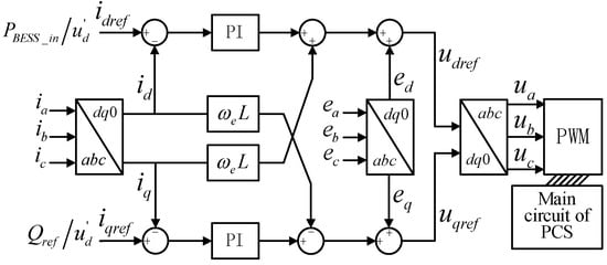
Figure 8.
Active power control model of the BESS.
The capacity for BESS is estimated as follows. Since the quantification of the virtual inertia is based on the maximum utilization of the rotor kinetic energy, the maximum energy released by BESS can be expressed as:
where ωr_max and ωr_min are the rotor speed limits of the DFIG unit in per-unit forms, and they are usually constants. Energy is the integral of power, so ΔEBESS can also be expressed as:
where PBESS and are the real-time and average active power of a BESS, respectively, Δt is the duration of active power support in inertia response. Combining Equations (25) and (26), can be obtained as shown in Equation (27).
Therefore, the required capacity QBESS of the BESS is calculated as follows:
where τ is estimated factor for capacity, its range is usually 1~3; SOClimu and SOClimd are the upper and lower limits of the SOC allowed by BESS, respectively; ΔT is the duration of primary frequency regulation. In this paper, SOClimu = 0.9, SOClimd = 0.1 and ΔT = 30 s.
6. Wind-Storage Combined Virtual Inertial Control Based on Quantization and Regulation Decoupling of Active Power Increments
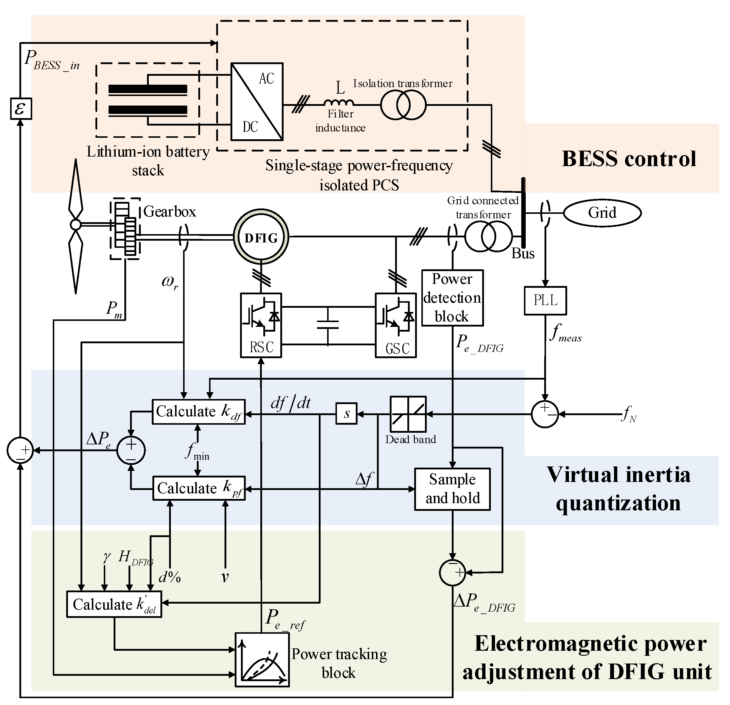
Figure 9 shows the detailed principles of wind-storage combined virtual inertial control based on quantization and regulation decoupling of active power increments. The control method consists of three main parts, with decoupled control of virtual inertia quantization and regulation as its core. First, based on the principle of maximizing the utilization of the kinetic energy of the rotor, the virtual inertia ΔPe of the DFIG unit is quantified by the control method in Section 3. It provides a reference for the total active power outputs of the unit and BESS. Secondly, the RoCoF-based curve-shifting method in Section 4 is adopted to adjust the electromagnetic power of the DFIG unit. It enables the unit to respond to frequency disturbances more rapidly while alleviating or even eliminating SFD. Finally, the difference between ΔPe and the active power increment ΔPe_DFIG of the unit is the amount of active power the BESS needs to supply to compensate for the unit’s power shortage during frequency regulation. Consequently, the strength of active power support in the inertial response is improved.
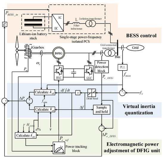
Figure 9.
Wind-storage combined virtual inertial control based on quantization and regulation decoupling of active power increment.
7. Simulation Results and Discussion
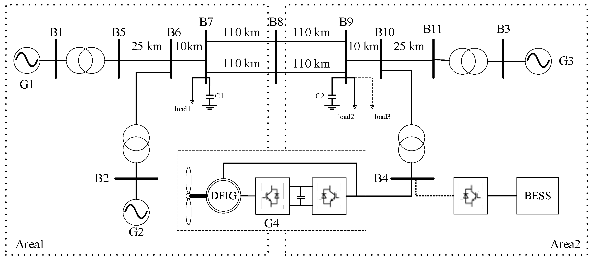
An IEEE four-machine two-area power system is constructed on the platform of MATLAB/Simulink as shown in Figure 10. G1, G2, and G3 are all SG units with rated capacities of 300 MW, 200 MW, and 300 MW, respectively. G4 is an equivalent wind farm with a rated capacity of 300 MW, which comprises 200 DFIG units, and the inherent inertia time constant is 4.7 s. A 24 MW/6 MWh BESS is connected in parallel with G4 at the grid-connected bus. Load1 and load2 are the system loads of areas 1 and 2 in steady state, with rated powers of 420 MW and 250 MW, respectively. When the system is running in a steady-state, the disturbance load (load3)—with a rated power of 50 MW—is set to be increased suddenly at 2 s, so as to verify the effectiveness of the control method.

Figure 10.
Diagram of a four-machine two-area power system.
Due to the short duration of the inertial response, the wind speed can be considered to be approximately constant. The DFIG units operate in a de-loading mode, with a de-loading ratio of 10%. Since the control method is a combination of several methods, comparative simulations were carried out from three aspects: (1) quantization of virtual inertia, (2) the curve-shifting method based on RoCoF, and (3) the proposed wind-storage combined control method. Every aspect was simulated in two wind conditions. One is 9.5 m/s of wind speed which is a ‘relatively high wind speed condition’; and another is 7 m/s which is a ‘relatively low wind speed condition’. Seven kinds of simulation cases are provided, as shown in Table 1. Cases 1, 2, and 3 are cases of virtual inertial control based on the P-D algorithm. Case 3 adopts the virtual inertia quantization control approach described in Section 3. Cases 4 and 5 use the curve-shifting method, and Case 5 uses the control method proposed in Section 4. Case 6 is the proposed wind-storage combined virtual inertial control system. Case 7 considers a case where the wind farm does not participate in frequency regulation.

Table 1.
Descriptions of the simulation cases.
7.1. Simulation Results of Virtual Inertia Quantization Control
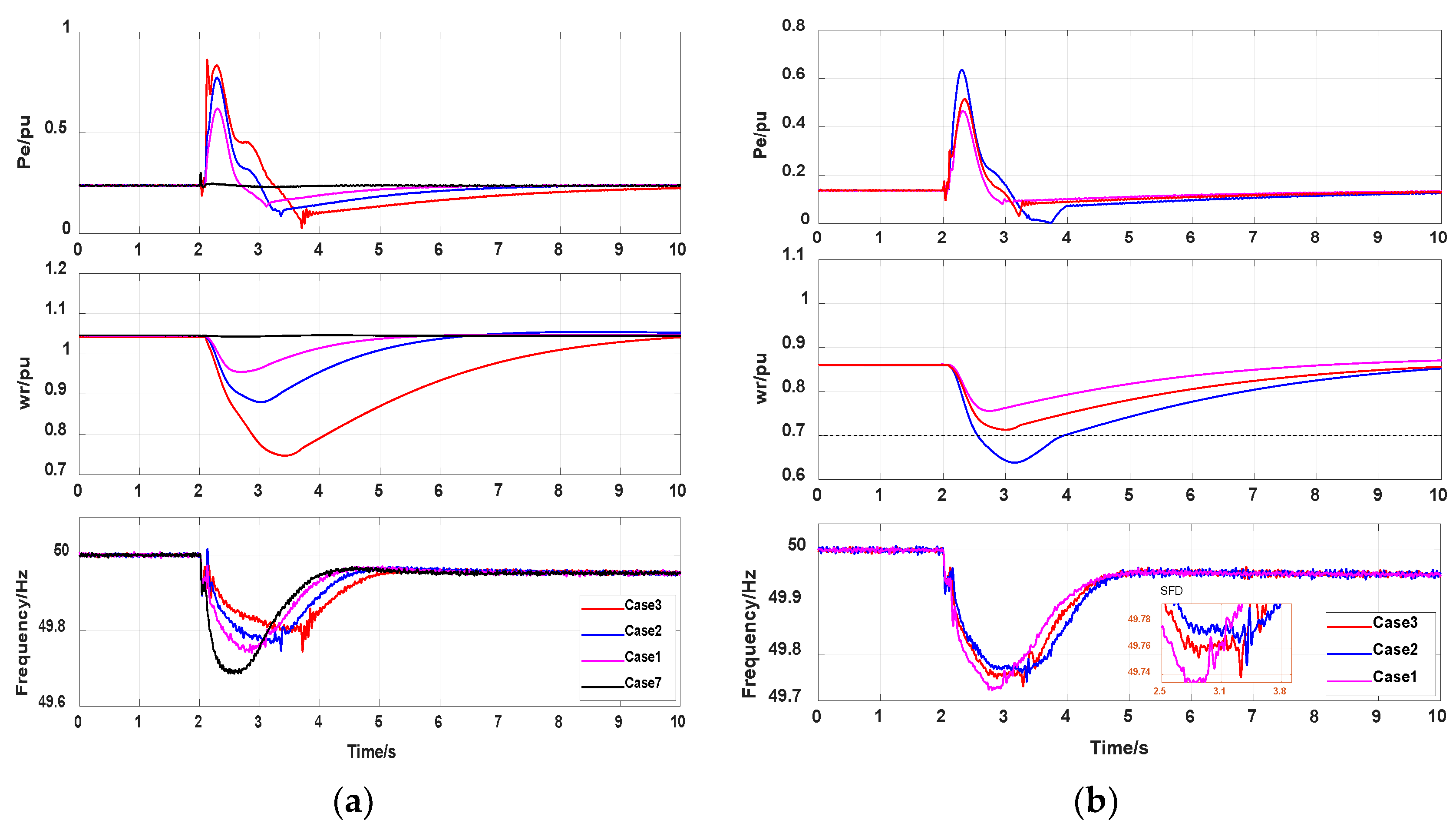
The quantization control system proposed in Section 3 was directly introduced into the active power control loop of the DFIG unit as a frequency-regulated method. The simulation results for Cases 1, 2, 3, and 7 are compared in Figure 11. Case1 and 2 used traditional P-D controls with fixed coefficients, and the kdf and kpf were set by trial and error.
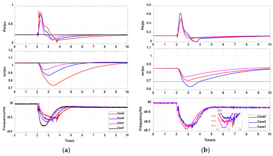
Figure 11.
Simulation results of virtual inertia quantization control. (a) Relatively high wind speed condition. (b) Relatively low wind speed condition.
7.1.1. Relatively High Wind Speed Condition
The simulation results under the high wind speed are shown in Figure 11a. The nadir of the unit’s rotor speed drop in Case 3 is 0.76 pu, which is lower than those in Cases 1 and 2 and is the closest to the speed limit. The kinetic energy of the rotor is almost entirely utilized. Therefore, according to the simulations of frequency, Case 3 provides an optimal inhibition effect of the RoCoF. This shows that the proposed virtual inertia quantization control method can improve the rotor’s kinetic energy utilization and the active support strength of the unit, thereby verifying the effectiveness of the quantization method. However, Case 3 shows a more serious SFD than Cases 1 and 2 due to the large drop in rotor speed. The nadir of the frequency drop is 49.73 Hz, which is the lowest of all cases (except Case7) and may trigger the UFLS during the stage of rotor speed recovery. The nadir in Case 2 is 49.74 Hz. In Case 1, due to the smaller variation in rotor speed, the K-coefficient is low and avoids an SFD. This also confirms that the P-D algorithm harms the frequency stability if the rotor kinetic energy is excessively consumed.
7.1.2. Relatively Low Wind Speed Condition
The simulation results under the low wind speed are shown in Figure 11b. The suppression of the RoCoF is best in Case 2, which is different from the high wind speed case. However, it should be noted that the rotor speed drop in Case 2 exceeds the speed limit of the unit (0.7 pu). The DFIG unit is cut off if speed protection is not set, which will have more adverse effects on the grid’s frequency stability. The rotor speed in Case 3 drops to 0.73 pu, which is within the safe range. Thus, the frequency-regulated capability of the unit under a relatively low wind speed is effectively quantified. In the frequency simulation result, SFD phenomena appear in both Case 2 and 3, but their amplitude of decrease is less than that under the high wind speed condition. The reason is that the SG units in the grid output more active power for frequency regulation at lower wind speeds, resulting in less rotor speed variation in the DFIG unit.
The superiority of the proposed quantification method is verified by these comparative simulations under different wind speeds. It can accurately measure the frequency-regulated capability of the DFIG unit according to the wind conditions, so as to provide a reasonable reference for the total active power increment of the wind-storage system.
7.2. Simulation Results of Active Power Regulation by the DFIG Unit Based on the Curve-Shifting Method
The proposed curve-shifting method based on the RoCoF was also simulated at two wind speed conditions. The results are compared with those of Case 4 and Case3 to verify that the method improves the inertial response speed and to observe its suppression effect on SFD, as shown in Figure 12. Because the power tracking curve coefficients in Case 5 change with the RoCoFs, they rapidly increase to a maximum at the instant of frequency regulation. Consequently, the active power outputs of the unit show a vertical upward trend. On the other hand, in Case 4, the power tracking curve coefficients are adjusted based on the frequency deviations, so the active power outputs show a slow increase. Overall, although the two cases have roughly the same amplitude of rotor speed drop in both wind conditions, Case 5 inhibits the RoCoF more effectively due to the advantage of its higher active power response speed. Its frequency drop nadirs are 0.04 Hz and 0.03 Hz higher than those of Case 4 under the high and low wind speeds, respectively. In addition, the rotor speeds can be recovered faster. The magnitude of the increase in kopt is the same under both wind speeds. However, the rotor stores less energy at low wind speeds, so ΔPe_DFIG is weaker. In terms of inhibiting the SFD, Cases 4 and Case 5 do not show the SFD phenomenon. Moreover, it can be seen from the simulation results of Pe that the negative power disturbance of the DFIG unit during frequency regulation is effectively improved compared with Case 3 in both conditions. This is due to the limitation of the shifting range of the power tracking curve. Therefore, in different wind conditions, the curve-shifting method based on RoCoF not only achieves the same active power response speed as the P-D algorithm but also successfully avoids the occurrence of SFD. However, the disadvantage is that the strength of active power support of Case 5 is weaker than that of Case 3 and the rotor’s kinetic energy is insufficiently utilized; hence, the improvement in the virtual inertia of the unit is limited.
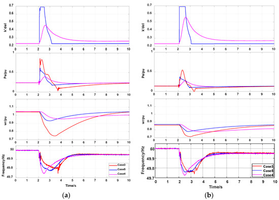
Figure 12.
Simulation results of active power regulation based on the curve-shifting method. (a) Relatively high wind speed condition. (b) Relatively low wind speed condition.
7.3. Simulation Results of Wind-Storage Combined Virtual Inertial Control
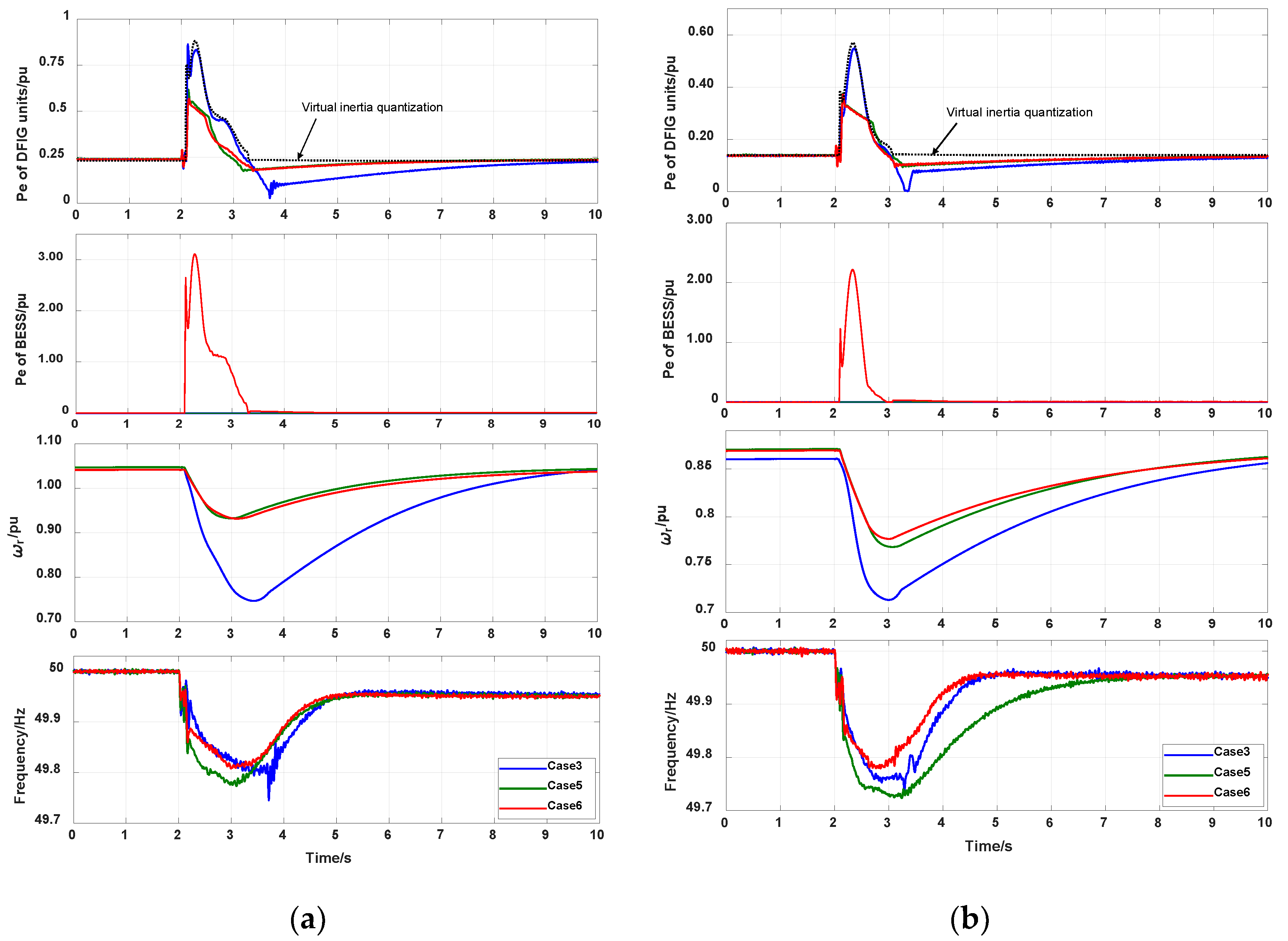
For the wind-storage combined virtual inertial control proposed in this paper, that is Case 6, simulations were carried out under different wind speeds. The results are compared with those of Case 3 and Case 5 to verify the co-improvement of suppressing SFD and increasing the strength of active power support, as shown in Figure 13.
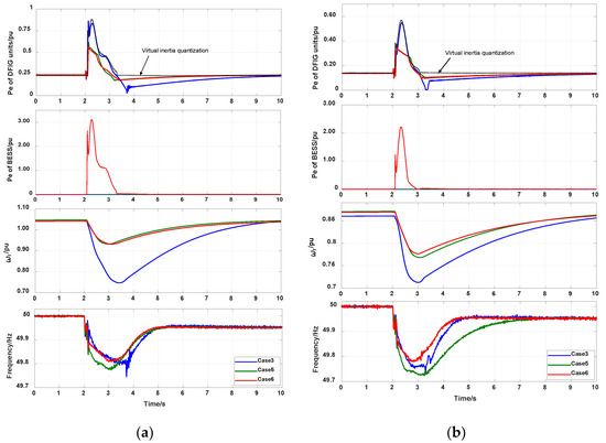
Figure 13.
Wind-storage simulation results of combined virtual inertial control. (a) Relatively high wind speed condition. (b) Relatively low wind speed condition.
7.3.1. Relatively High Wind Speed Condition
Figure 13a and Table 2 show the simulation results under the relatively high wind speed condition. In Table 2, all the values of active power are their top values. Case 3 has the greatest utilization of rotor kinetic energy and strong active power support. However, the frequency nadir drops from the expected 49.81 Hz to 49.74 Hz due to SFD. Case 5 eliminates the SFD by using the curve-shifting method, but the active power support is insufficient because the translation range of the power tracking curve is constrained. Case 6 avoids the defects of Cases 3 and 5 owing to the assistance of the BESS and the decoupling of the quantization and regulation of the active power increments. The black dotted line in Figure 13 represents the quantization curve of virtual inertia, which is roughly the same as the result of the active power dynamic response in Case 3. This indicates that the quantization method can be successfully applied to wind-storage combined virtual inertial control. In addition, the actual output of the unit and the trajectory of change in the rotor speed in Case 6 are similar to those in Case 5, thus avoiding the SFDs during response. Finally, the BESS outputs compensatory active power according to the quantized value of virtual inertia. It can be seen from the frequency simulation results of Case 6 that the downward trend in RoCoF is effectively suppressed in the initial stage of the inertial response due to the combined output of wind and the BESS. The frequency nadir is increased to 49.82 Hz, which is the best among the three cases. Therefore, using the method of case 6 not only eliminates the SFD but also improves the support strength of active power in the virtual inertial response.
Table 2.
Simulation results under the relatively high wind speed.
7.3.2. Relatively Low Wind Speed Condition
To demonstrate the universality of the control method, a simulation was carried out under the relatively low wind speed condition (Figure 13a and Table 3). In the figure, the quantized value of virtual inertia is significantly lower than that under the high wind speed condition. This shows that the quantification method can reasonably quantify the frequency-regulated capability of the DFIG unit according to the wind speed, rather than the proportion of wind power in the power grid. This is very different from quantification methods based on the wind farm or grid level. Due to the low wind speed, the steady-state operating point of the DFIG unit moves down. The rotor can release less energy than at higher wind speeds. Therefore, although the amplitude of rotor speed decrease in Case 5 is almost the same as that at high wind speed, the strength of the active power support is weakened, causing its frequency nadir to drop to 49.73 Hz. In Case 3, although the kinetic energy of the unit’s rotor is utilized to the maximum, the SFD phenomenon still occurs, so the frequency nadir is close to that in Case 5. However, Case 6 still has fine performance in inhibiting SFD and improving virtual inertia at a relatively low wind speed.
Table 3.
Simulation results under the relatively low wind speed.
To sum up, it can be seen from the results listed in Table 2 and Table 3 that the sum of ΔPe_DFIG and Pe_BESS can just attain the requirements of virtual inertia quantization. It is worth mentioning that for a wind-storage combined virtual inertial control, reference [28] used fuzzy controllers to achieve similar effects to this paper. However, the method lacks quantitative analysis of the frequency-regulated capability of the wind turbine, and the control accuracy of the fuzzy algorithm is limited, so its applicability is not as good as that of the method proposed in this paper.
8. Conclusions
Based on a comparative analysis of current virtual inertial control methods for DFIG units, this paper highlights that there is a conflict between suppressing SFD and increasing the strength of active power support during a virtual inertial response. To solve this issue, the quantization and regulation of the active power increments for frequency regulation were first decoupled. Then, different virtual inertial control methods were ameliorated and combined, while a BESS was employed to compensate for active power shortages. Finally, a wind-storage combined virtual inertial control model was established. Through the contrastive simulations, the following conclusions can be drawn.
- (1)
- A wind-storage combined virtual inertial control method based on quantization and regulation decoupling of active power increments is proposed.
- (2)
- The method quantifies the total virtual inertia of the wind-storage system at the DFIG unit level based on the principle of maximizing the utilization of the rotor’s kinetic energy. It effectively improves the quantification accuracy of virtual inertia compared with previous methods based on the wind farm or grid levels. A curve-shifting method based on RoCoF is used to adjust the active output of the unit. It not only makes up for the shortcoming of the slow response speed of traditional methods but also effectively inhibits the SFD. Moreover, the method further improves the coordination mechanism of wind-storage, so that the BESS can participate in the whole process of inertial response to enhance the active power strength.
- (3)
- The decoupled control system gives full play to the advantages of the P-D algorithm, curve-shifting method, and BESS. By this combination, the inhibition of the SFD and the increasing of the active power support strength are both improved during virtual inertial response.
- (4)
- The duration of the virtual inertial response is short. In order to improve the frequency steady-state error after disturbance, future research will continue to explore wind-storage combined primary frequency regulation control based on this method.
Author Contributions
Conceptualization, D.M. and W.L.; Data curation, D.M.; Funding acquisition, W.L.; Investigation, D.M. and W.L.; Methodology, D.M.; Project administration, W.L.; Resources, W.L.; Supervision, W.L.; Validation, D.M.; Visualization, D.M.; Writing–original draft, D.M.; Writing—review and editing, W.L. All authors have read and agreed to the published version of the manuscript.
Funding
This research was funded by TECHNOLOGY PROJECT OF INNER MONGOLIA POWER (GROUP) CO., LTD. Funder: INNER MONGOLIA POWER (GROUP) CO., LTD, China. Funding number: 2022-17. The APC was funded by 2022-17.
Institutional Review Board Statement
Not applicable.
Informed Consent Statement
Not applicable.
Data Availability Statement
The data presented in this study are available on request from the corresponding author. The data are not publicly available due to privacy.
Conflicts of Interest
The authors declare no conflict of interest.
References
- Xuzhu, D.; Zhuhu, H.; Lei, S. Morphological characteristics and technology prospect of new distribution system. High Volt. Eng. 2021, 47, 3021–3031. [Google Scholar] [CrossRef]
- Liu, H.; Peng, X.; Zhang, C.; Zhang, S. Overview of wind power participating in frequency regulation control strategy for power system. Electr. Power Autom. Equip. 2021, 41, 81–88. [Google Scholar] [CrossRef]
- Zhang, Z.; Zhang, N.; Du, E.; Kang, W.; Whang, Z. Review and countermeasures on frequency security issues of power systems with high shares of renewables and power electronics. Proc. CSEE 2021, 8, 1–15. [Google Scholar] [CrossRef]
- Yu, H. Overview of HVRT technical measures for DFIG. In Proceedings of the International Symposium on Resource Exploration And Environmental Science (REES 2017), Ordos, China, 14–16 April 2017; pp. 1–8. [Google Scholar] [CrossRef] [Green Version]
- Xiong, L.; Li, P.; Wu, F.; Wang, J. Stability enhancement of power systems with high DFIG-wind turbine penetration via virtual inertia planning. IEEE Trans. Power Syst. 2019, 34, 1352–1361. [Google Scholar] [CrossRef]
- Shao, H.; Cai, X.; Zhou, D.; Li, Z.; Zheng, D.; Cao, Y.; Wang, Y.; Rao, F. Equivalent modeling and comprehensive evaluation of inertia emulation control strategy for DFIG wind turbine generator. IEEE Access 2019, 7, 64798–64811. [Google Scholar] [CrossRef]
- Chai, R.; Li, W. Research on wind-storage joint frequency modulation control strategy based on DFIG frequency modulation capability. In Proceedings of the 2021 IEEE 4th International Electrical and Energy Conference (CIEEC), Wuhan, China, 28–30 May 2021; pp. 1–8. [Google Scholar] [CrossRef]
- Li, Y.; Wang, D.; Fan, L.; Yuan, C.; Zhao, Y.; Kang, J. Variable coefficient control strategy for frequency stability of DFIG under power-limited operation. Power Syst. Technol. 2019, 43, 2910–2916. [Google Scholar] [CrossRef]
- Zhao, J.; Lyu, X.; Fu, Y.; Hu, X.; Li, F. Coordinated microgrid frequency regulation based on DFIG variable coefficient using virtual inertia and primary frequency control. IEEE Trans. Energy Convers. 2016, 31, 833–845. [Google Scholar] [CrossRef]
- Xie, Y.; Xie, Z.; Chang, Y.; Zhang, L. Virtual inertia adaptive control strategy for DFIG wind turbines based on the improved Bang-Bang control. In Proceedings of the 2020 IEEE 9th International Power Electronics and Motion Control Conference (IPEMC2020-ECCE Asia), Nanjing, China, 29 November–2 December 2020; pp. 1935–1939. [Google Scholar] [CrossRef]
- Ke, X.; Zhang, W.; Li, P.; Niu, S.; Sheng, S.; Yang, J. Fuzzy adaptive virtual inertia control for high wind power penetration system. Power Syst. Technol. 2020, 44, 2127–2134. [Google Scholar] [CrossRef]
- Li, B.; Zhang, F.; Ding, L. Fuzzy cooperative control and parameter correction strategy of speed controller in frequency modulation stage of doubly-fed induction generator. Power Syst. Technol. 2021, 7, 1–8. [Google Scholar] [CrossRef]
- Li, S.; Wang, W.; Zhang, X.; Li, C. Fuzzy adaptive virtual inertia control strategy of wind turbines based on system frequency response interval division. Power Syst. Technol. 2021, 45, 1658–1664. [Google Scholar] [CrossRef]
- Zhang, W.; Wu, C.; Huang, W.; Gao, H.; Cheng, M.; Xin, H. Evaluation of system frequency characteristic and parameter setting of frequency regulation for wind power considering frequency secondary drop. Autom. Electr. Power Syst. 2022, 2, 1–8. [Google Scholar] [CrossRef]
- Peng, X.; Jia, J.; Zhou, J.; Huang, S.; Wei, S. Speed Regulation Strategy Based on Variable Proportion Coefficient for Optimizing Inertial Response of Wind Generator. Proc. CSEE 2018, 38, 5625–5635. [Google Scholar] [CrossRef]
- Xu, Y.; Yang, D.; Huang, J.; Zhang, X.; Hua, L. Fast Stepwise Inertial Control Scheme of a DFIG for Reducing Second Frequency Drop. Appl. Sci. 2021, 11, 8259. [Google Scholar] [CrossRef]
- Fu, Y.; Wang, Y.; Zhang, X.; Hei, Y. Analysis and integrated control of inertia and primary frequency regulation for variable speed wind turbines. Proc. CSEE 2014, 34, 4706–4714. [Google Scholar] [CrossRef]
- Liang, K.; Peng, X.; Zhou, J.; Wang, R.; Li, F. Synergetic control based on rotor speed regulation with variable proportional coefficient for doubly-fed wind turbines implementing virtual inertia support. In Proceedings of the 8th Renewable Power Generation Conference (RPG2019), Shanghai, China, 24–25 October 2019; pp. 1–8. [Google Scholar] [CrossRef]
- Danny, O.; Sergio, M. Frequency dependent strategy for mitigating wind power fluctuations of a doubly-fed induction generator wind turbine based on virtual inertia control and blade pitch angle regulation. Renew. Energy 2018, 128, 108–124. [Google Scholar]
- Ouyang, J.; Yuan, Y.; Li, M.; Pang, M.; Jiang, H.; Zhong, L. Optimal Dispatching Method of High-proportion Wind Power Systems Considering Wind Power Reserve for Frequency Adjustment. Power Syst. Technol. 2021, 45, 2192–2200. [Google Scholar] [CrossRef]
- Miao, L.; Wen, J.; Xie, H.; Yue, C.; Lee, W.J. Coordinated Control Strategy of Wind Turbine Generator and Energy Storage Equipment for Frequency Support. IEEE Trans. Ind. Appl. 2015, 51, 2732–2742. [Google Scholar] [CrossRef]
- Abouzeid, S.I.; Guo, Y.; Zhang, H. Cooperative control framework of the wind turbine generators and the compressed air energy storage system for efficient frequency regulation support. Int. J. Electr. Power Energy Syst. 2021, 9, 106844. [Google Scholar] [CrossRef]
- Zhao, J.; Li, M.; He, X.; Zhu, R. Coordinated Control Strategy of Wind Power and Energy Storage in Frequency Regulation Based on Torque Limit Control. Trans. China Electrotech. Soc. 2019, 34, 4982–4990. [Google Scholar] [CrossRef]
- Kim, H.; Lee, J.; Lee, J.; Jang, G. Novel Coordinated Control Strategy of BESS and PMSG-WTG for Fast Frequency Response. Appl. Sci. 2021, 11, 3874. [Google Scholar] [CrossRef]
- Jiang, H.; Cai, J.; Xiao, R.; Wang, S.; Xie, Y.; Tang, X. A wind-storage coordinated control strategy for improving system frequency response characteristics. Electr. Power Autom. Equip. 2021, 41, 44–50. [Google Scholar] [CrossRef]
- Yan, X.; Sun, X.; Cui, S.; Li, X.; Li, T. Improved control strategy for inertia and primary frequency regulation of doubly fed induction generator based on rotor kinetic energy and supercapacitor energy storage. Trans. China Electrotech. Soc. 2021, 36, 179–188. [Google Scholar] [CrossRef]
- Bao, W.; Wu, Q.; Ding, L.; Huang, S.; Teng, F.; Terzija, V. Synthetic inertial control of wind farm with BESS based on model predictive control. IET Renew. Power Gener. 2020, 14, 2447–2455. [Google Scholar] [CrossRef]
- Peng, B.; Zhang, F.; Liang, J.; Ding, L.; Liang, Z.; Wu, Q. Coordinated control strategy for the short-term frequency response of a DFIG-ES system based on wind speed zone classification and fuzzy logic control. Electr. Power Energy Syst. 2019, 107, 363–378. [Google Scholar] [CrossRef]
- Wang, B.; Yang, D.; Cai, G.; Ding, L.; Liang, Z.; Quiwei, W. Review of research on power system inertia related issues in the context of high penetration of renewable power generation. Power Syst. Technol. 2020, 44, 2998–3006. [Google Scholar] [CrossRef]
- Chen, P.; Qi, C.; Chen, X. Virtual inertia estimation method of DFIG-based wind farm with additional frequency control. J. Mod. Power Syst. Clean Energy 2021, 9, 1076–1086. [Google Scholar] [CrossRef]
- Qin, X.; Su, L.; Chi, Y.; Guo, Q.; Xu, X. Functional orientation discrimination of inertia support and primary frequency regulation of virtual synchronous generator in large power grid. Autom. Electr. Power Syst. 2018, 42, 36–41. [Google Scholar] [CrossRef]
- Shi, Q.; Liu, L.; Wang, Y.; Lu, Y.; Zou, Q.; Zhang, Q.; Liu, H. Cooperative synthetic inertia control for wind farms considering frequency regulation capability. Front. Energy Res. 2021, 8, 738857. [Google Scholar] [CrossRef]
- Li, H.; Zhang, X.; Wang, Y.; Zhu, X. Virtual inertia control of DFIG-based wind turbines based on the optimal power tracking. Proc. CSEE 2012, 32, 32–38. [Google Scholar] [CrossRef]
- Wang, C.; Xu, J.; Wang, L.; Song, D. Research on optimization strategy of grid frequency modulation based on doubly-fed wind turbines. Int. J. Low-Carbon Technol. 2021, 16, 229–239. [Google Scholar] [CrossRef]
- Wang, T.; Zhang, F.; Ding, L. Frequency regulation control strategy of over-speed wind turbines considering optimal operation point. Electr. Power Autom. Equip. 2021, 41, 22–27. [Google Scholar] [CrossRef]
- Tu, S.; Zhang, B.; Jin, X. Research on DFIG-ES system to enhance the fast-frequency response capability of wind farms. Energies 2019, 12, 3581. [Google Scholar] [CrossRef] [Green Version]
- Feng, Y.; Xie, Z. Coordinated primary frequency regulation and inertia response based on DFIG using over speed and torque reserve. In Proceedings of the 36th Chinese Control Conference (CCC), Dalian, China, 26–28 July 2017; pp. 9141–9144. [Google Scholar] [CrossRef]
- Bian, X.; Zhang, J.; Ding, Y.; Li, D.; Zhao, J.; Zhu, L. Double layer adaptive dynamic frequency optimization control of microgrid based on DFIG virtual inertia. High Volt. Eng. 2020, 46, 1489–1497. [Google Scholar] [CrossRef]
- Ujjwal, D.; Akhtar, K.; Shi, J. The relevance of large-scale battery energy storage (BES) application in providing primary frequency control with increased wind energy penetration. J. Energy Storage 2019, 23, 9–18. [Google Scholar] [CrossRef]
- Yoong, Y.L.; Chia, A.O.; Muhammad, N.H. Performance evaluation of grid-connected power conversion systems integrated with real-time battery monitoring in a battery energy storage system. Electr. Eng. 2020, 102, 245–257. [Google Scholar] [CrossRef]


Publisher’s Note: MDPI stays neutral with regard to jurisdictional claims in published maps and institutional affiliations. |
© 2022 by the authors. Licensee MDPI, Basel, Switzerland. This article is an open access article distributed under the terms and conditions of the Creative Commons Attribution (CC BY) license (https://creativecommons.org/licenses/by/4.0/).