Article

Dynamic Response Analysis of a Novel Anti-Impact Pressure Balance Jack

1
College of Mechanical and Electrical Engineering, Shandong University of Science and Technology, Qingdao 266590, China
2
State Key Laboratory of Mining Disaster Prevention and Control Cofounded by Shandong Province and the Ministry of Science and Technology, Shandong University of Science and Technology, Qingdao 266590, China
3
College of Information Science and Engineering, Shandong Normal University, Jinan 250358, China
*
Author to whom correspondence should be addressed.
Energies 2022, 15(14), 5236; https://doi.org/10.3390/en15145236
Submission received: 23 June 2022 / Revised: 15 July 2022 / Accepted: 18 July 2022 / Published: 19 July 2022

Abstract

:
Coal resources perform an important role in China’s energy structure. Hydraulic support is the main supporting equipment of fully mechanized mining face in coal mines. Because the hydraulic support frequently bears the impact pressure from the working face, it is very easy to cause failure of the balance jack. In order to solve the problem that the balance jack easily damaged by impact and improve the impact resistance of the hydraulic support, an improved fast response balance jack with multiple adaptive buffers was proposed in this paper. The energy dissipation characteristics of the balance jack were analyzed by establishing the mathematical model of the multiple buffering process of it. Based on ADAMS, the dynamic simulation model of the hydraulic support was constructed, and the mechanical response characteristics of the proposed balance jack and the traditional balance jack under different impact loads were compared and analyzed. By changing the equivalent stiffness of the novel balance jack system, the influence of different initial inflation pressure and length of the buffer cavity on the dynamic performance of the novel balance jack was discussed. The results show that compared with the traditional balance jack, the multi-adaptive response balance jack proposed in this paper can reduce the peak force of the hinge point by about 24.6% and the fluctuation frequency was also significantly reduced under the ultimate load condition at the front end of the top beam, which has better impact resistance. When the initial inflation pressure of the buffer cavity is 40~45 MPa and the initial length is less than 105 mm, a better buffer effect can be achieved. This study provides a new solution to solve the failure problem of the balance jack under the underground impact pressure and improve the safety and reliability of hydraulic support.

1. Introduction

China is rich in coal resources and production. Coal resources perform an important role in China’s energy structure [1]. Hydraulic support is the main supporting equipment of fully mechanized mining face in coal mines [2]. The two-column shield hydraulic support is widely used because of its simple structure and strong adaptability. The posture of the two-column shield hydraulic support is adjusted by the balance jack of the key components to make it in a reasonable working position [3,4]. The load types of hydraulic support in the working process are mainly static load and impact load [5]. With the continuous improvement of mining intensity and mining depth, the high-strength impact load frequently acts on hydraulic support [6,7,8], causing the balance jack, its connecting ear seat, and other parts to be easily damaged. This further affects the normal work of the hydraulic support and the smooth progress of fully mechanized mining [9,10].
With the application of ultra-large mining height technology, the failure of the balance jack occurs frequently in the working face with serious rock burst. Figure 1 shows the typical actual failure mode of the balancing jack, which is mainly manifested as: the piston rod connection is damaged, the piston rod is bent, the connecting pin shaft is broken, and the pin hole is deformed. Therefore, the development of a novel balance jack with large buffer capacity and fast response is of great application value to improve the impact resistance of hydraulic support.
In order to study the dynamic response of the key components such as the hydraulic support column and the balance jack under the impact load, and improve the impact resistance of the hydraulic support, scholars in China and abroad have conducted a lot of simulation and experimental studies on the hydraulic support. G.S.P. Singh and U.K. Singh put forward a numerical simulation method to predict the performance of hydraulic support. It was concluded that the dynamic load caused by coal seam collapse is the main cause of support collapse [11]. A.K. Verma and M. Shabanimashcool et al. established numerical models of a fully mechanized mining face and analyzed the interaction between the support and working face [12,13]. Andrzej Pytlik simulated the working process of the safety valve under impact load and proposed a new safety protection device to improve the response speed of unloading [14]. Dawid Szurgacz, through the dynamic load impact test of hydraulic support, concluded that the key to ensuring the safety work of the support is the safety valve, and more effective methods should be used to reduce the impact on the hydraulic support [15,16]. To study the dynamic response characteristics of hydraulic support under impact load. Liu Xinke established the dynamic characteristic analysis model of a hydraulic support column under impact load, and realized the numerical simulation of the dynamic response of a column under impact load [17]. Using the multi-body dynamics simulation analysis method, Wan Lirong analyzed the force change and force transfer process of the hydraulic support shield beam under impact load [18]. X.T. Zeng studied the motion trend and mechanical response of the support when the impact load acted on the top beam and the shield beam, indicating that the support was more vulnerable to damage when the impact load acted on the top beam and the shield beam simultaneously [19]. Z.K. Yang built a dynamic simulation platform for the rigid-flexible impact of an ultra-large mining height hydraulic support, and simulated the stress state of the hinge point when the support is subjected to impact load at different positions [20] to study the important role of the balance jack in the working process of hydraulic support. Yang Peiju pointed out that the balance jack performs an important role in keeping the posture stability of hydraulic support through field observation on the fully mechanized mining face [21]. Li Huamin et al. pointed out that the coal caving face in a thick coal seam is more likely to damage the traditional balance jack of hydraulic support due to the changeable position of coal caving [22]. Li Jianping and Xu Yajun studied the bearing characteristics of the hydraulic support. It was concluded that increasing the working resistance of the balance jack can effectively improve the bearing capacity of the support [23,24]. Liang Lichuang established the ADAMS dynamic simulation model of the hydraulic support, studied the force transfer characteristics of each hinge point when the support top beam was subjected to impact load at different positions, and obtained that the position of impact load had greater influence on the force of the hinge point of the top beam and shield beam and the hinge point of the balance jack [25]. The ADAMS rigid-flexible coupling model of hydraulic support was established by Zeng Qingliang. The load changes in hinge points and key components of hydraulic support under different roof pressures were analyzed. It was concluded that load on hydraulic support has great influence on the force of hinge points, columns, and the balance jack [26,27]. Meng Zhaosheng analyzed the stability of hydraulic support with a large mining height. It was concluded that the working resistance and position of the balance jack have great influence on the hydraulic support [28]. To solve the failure problem of the balance jack, Wang Guofa proposed to install a mechanical limiting device between the top beam and the shield beam to prevent the damage to the balance jack and its connecting ear pedestal [29]. Shang Huiling et al. proposed using a large flow safety valve to improve the shock resistance of the balance jack [30]. Sun Yufei added the inner overflow circuit in the hydraulic control circuit of the balance jack, which effectively improved the filling speed and support efficiency [31].
The existing literature has conducted a lot of analysis and research on the mechanical response and dynamic response of the key components of the hydraulic support and the failure and protection of the balance jack under impact pressure. However, most of the existing research regards the balance jack as a whole elastic element, which cannot effectively study the dynamic response of the balance jack under the underground impact pressure. Moreover, the current solutions for the damage to the balance jack cannot completely overcome the problem that the balance jack easily fails under the underground impact pressure. Therefore, to improve the response speed of the balance jack and its impact resistance, this paper proposed an improved fast response balance jack with multiple adaptive buffers. Moreover, the dynamic response characteristics and influencing factors of the novel balance jack after impact were analyzed and studied.

2. Materials and Methods

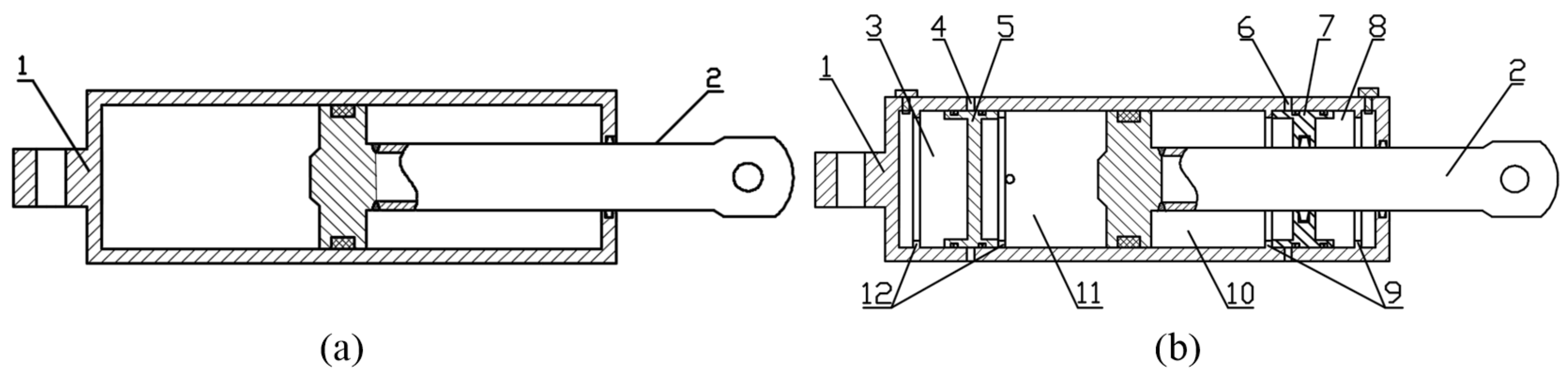
2.1. Structure Analysis of the Novel Balance Jack with Multiple Adaptive Buffers

Figure 2 is the structure comparison diagram of the traditional balance jack and the multi-adaptive response balance jack [32]. It can be seen from the comparison between Figure 2 that compared with the traditional balance jack, the buffer cavity is added on both sides of the multi-adaptive response balance jack to achieve the purpose of fast buffer and multiple protection. The floating piston is used to separate the oil cavity from the buffer cavity, and controls the opening and closing of the unloading hole on the cylinder body. The position of the floating piston is limited by the limit boss to prevent the floating piston from hindering the normal operation of the balance jack. In addition, when the balance jack is impacted and the oil in the oil cavity is completely overflowed, the piston rod reaches the stroke limit, and the rigid contact between the piston rod and the limit boss can offset part of the impact force. If the contact force is too large, it also damages the limit boss and the piston rod itself.
When the impact pressure acts on the front end of the top beam of the hydraulic support, the balance jack is pressed rapidly, and the pressure in the rodless cavity increases rapidly. If the safety valve can respond in time, it shall be unloaded by the safety valve firstly. If the safety valve fails to respond in time, it shall be quickly buffered by compressing the buffer cavity until the pressure increases to the opening pressure of the unloading hole on the cylinder body, and the unloading hole on the cylinder body begins overflow unloading. On the contrary, when the impact pressure acts on the rear end of the top beam or the shield beam, resulting in the tension of the balance jack, the principle is similar to the compression process.

2.2. Multi-Adaptive Response Balance Jack Buffer Process Modeling

The buffering process of multi-adaptive response balance jack proposed in this paper can be divided into four stages. In order to analyze the energy dissipation mechanism of each buffer process, detailed derivation and analysis are carried out for each stage.
(1)
Compression oil stage: The oil pressure in the cavity is less than the opening pressure of the safety valve and the equivalent stiffness of the oil is calculated by Equation (1):
k y = A β L
where ky is the oil equivalent stiffness, N/m; A is the effective area of hydraulic cylinder transmitting liquid force, m2; β is volume elastic modulus of emulsion, β = 1.95 Gpa; and L is the length of the effective liquid column in hydraulic cylinder, m.
(2)
The safety valve opening overflow stage: The balance jack shows constant pressure characteristics. The oil pressure in the cavity is always equal to the set pressure of the safety valve and the force is calculated by Equation (2):
F 1 = A P 1
where F1 is oil cavity equivalent force, N; P1 is safety valve setting pressure, MPa; and A is effective area of hydraulic cylinder transmitting liquid force, m2.
(3)
Compression buffer cavity stage: Due to the untimely response of the safety valve, the oil pressure in the cavity of the process is greater than the set pressure of the safety valve. Since the whole buffer process is complex, to facilitate the construction of the mathematical model of the process the following assumptions are made for the whole process: the heat exchange between the hydraulic cylinder and the outside during the buffering process are ignored; the compressibility, leakage, and viscosity change in oil are ignored; and the flow state is turbulent.
As shown in Figure 3, when the sealed high-pressure gas is used for buffering, as equivalent stiffness C [33], the internal energy E1 generated in the buffer cavity and the total mechanical energy E2 generated by the working parts in the buffering process are calculated by Equations (3)–(5).
C = 1.4 A 2 p 0 V 0 1.4 V 0 A x 2.4
E 1 = p c A c l c
E 2 = p p A p l p + 1 2 m 1 v 1 2 F f 1 L c + 1 2 m 2 v 2 2 F f 2 L c
where C is gas spring equivalent stiffness, N/m; A is Ggas effective area, m2; p0 is buffer cavity initial pressure, Mpa; V0 is buffer cavity initial volume, m3; x is floating piston displacement, m; pc is the average buffer pressure in buffer cavity; pp is the balance jack rodless cavity oil pressure; Ac is the Effective working area of buffer cavity; Ap is the Effective working area of rodless oil cavity; Lc is the Buffer stroke; m1 is the piston rod mass; v1 is the piston rod speed; Ff1 is the piston rod friction; m2 is the floating piston mass; v2 is the floating piston speed; and Ff2 is the floating piston friction.
When E1 = E2 the mechanical energy of the working parts is all absorbed by the buffer cavity gas, and thus:
p c = p p A p l p + 1 2 m 1 v 1 2 F f 1 L c + 1 2 m 2 v 2 2 F f 2 L c A c L c
(4)
The overflow stage of the cylinder unloading hole: The balance jack shows constant pressure characteristics. The oil pressure in the cavity is always equal to the opening pressure of the unloading hole on the cylinder body, and the force is:
F 2 = A P 2
where F2 is the oil cavity equivalent force, N; P2 is the setting pressure of cylinder unloading hole, MPa; and A is the effective area of hydraulic cylinder transmitting liquid force, m2.
Through the above analysis, the force characteristics and energy dissipation law of each buffer stage are obtained. The main influencing factors of the buffer process are clarified. This provides a theoretical basis for subsequent simulation analysis and parameter research.

2.3. Establishment of Impact Dynamic Simulation Model for Hydraulic Support

Figure 4 is the overall simulation model diagram of ZY21000/38/82D two-column shield hydraulic support. Figure 4a shows the simulation model of hydraulic support with the traditional balance jack, and Figure 4b shows the simulation model of hydraulic support with the novel balance jack. The maximum supporting height of this type of hydraulic support is 8.2 m, and the maximum working resistance is 21,000 kN. The support height selected in this paper is 6.65 m. The hinged shafts are connected by revolute pairs. The base and the ground are connected by a fixed pair. The oil cavity and buffer cavity of the column and the novel balance jack are replaced by the spring damping system and equivalent force, respectively. The force is directly applied to the top beam by STEP function. The stable load acts on the top column and the impact load acts on the front end of the middle line of the top beam. In order to ensure the accuracy of the model as much as possible and improve the analysis accuracy, the equivalent force of the column and the balance jack was set as the change function of the cylinder stroke through the AKISPL function.
The equivalent schematic diagram of the hydraulic support column, the traditional balance jack and the novel balancing jack with multiple adaptive responses are shown in Figure 5. The data in Table 1 is substituted into Equations (1), (3) and (8) to calculate the equivalent stiffness.
In addition, when the hydraulic support works in practice, the first cylinder of the column completely extends and the second cylinder begins to extend. Therefore, when the support height is 6.65 m, the two cylinders of the column are in a working state, which is equivalent to two equivalent springs in series. At this time, the total equivalent spring stiffness should be calculated by Equation (8):
k = k 1 k 2 k 1 + k 2
where k is total equivalent stiffness, N/m; k1 is the equivalent stiffness of the first cylinder, N/m; and k2 is the equivalent stiffness of the second cylinder, N/m.

2.4. Reliability Verification of Simulation Model

According to the column upper- and lower-cylinder initial pressure, Pup = 28 MPa and Plow = 29 MPa, respectively, combined with the column-specific size, the column upper- and lower-cylinder initial pressure can be calculated, Fup = 3175 kN and Flow = 6395 kN, respectively. The stable load of 14,000 kN was applied on the top beam near the column to obtain the working resistance and compression curve of the hydraulic support, as shown in Figure 6.
As shown in Figure 6, the force on the column increases with the increase in load, and the length of the column hardly changes before the load on the top beam reaches the initial support force of the column. When the load borne by the top beam is greater than the initial support force of the column, the column begins to be compressed with the increase in the load borne by the top beam. After the load is stable, the column height does not change. The force of the column after stabilization is about 7150 kN, which is slightly larger than half of the pressure load of the top beam, because the column also bears the gravity of the top beam, meeting the actual working conditions. Therefore, the model has certain reliability.

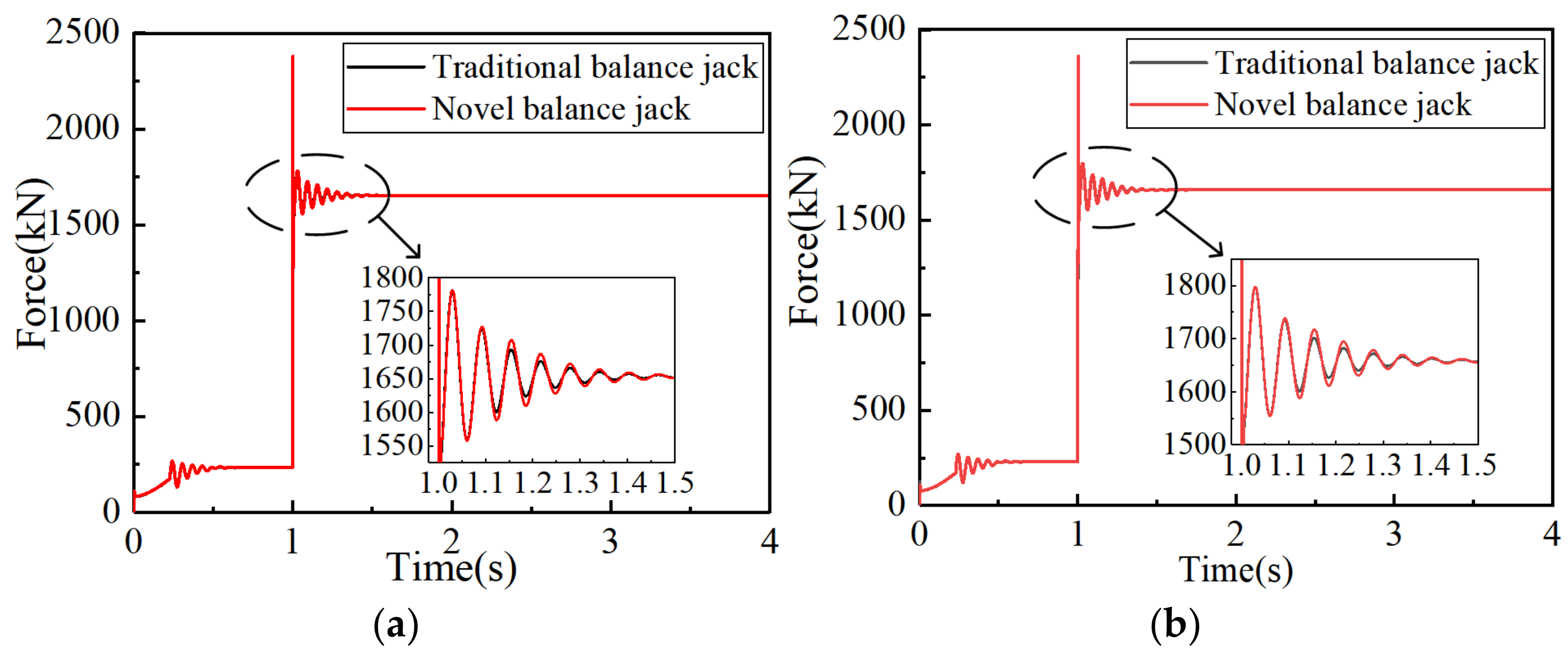
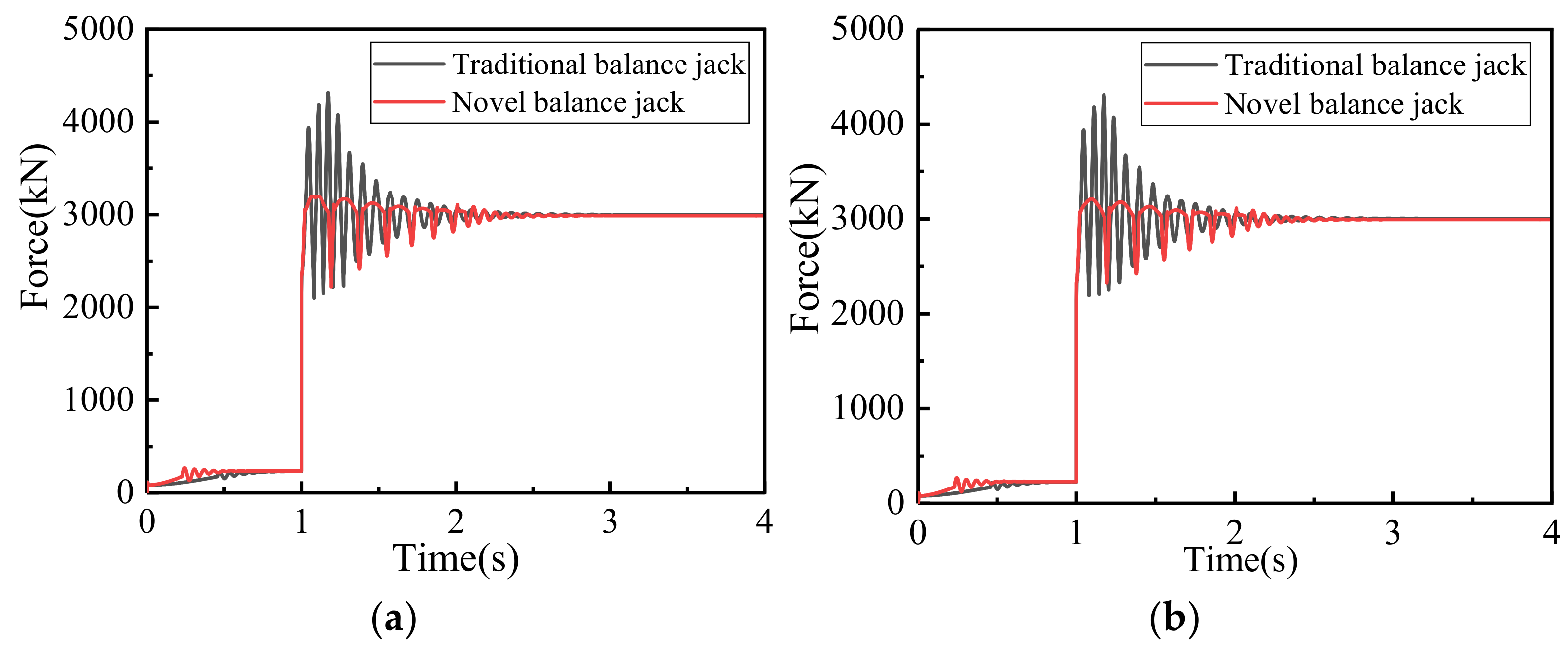
3. Comparative Analysis of Response Results under Different Impact Loads

When the simulation time is 1 s, the impact loads of 500 kN and 900 kN are applied to the front end of the top beam, respectively. On the premise that the safety valve does not respond, the mechanical response characteristics of the traditional balance jack and the novel balance jack with multi-adaptive response are compared and analyzed.
Figure 7 shows the force comparison between the traditional balance jack and the novel balance jack with multi-adaptive response when the front end of the hydraulic support top beam is subjected to 500 kN impact load. As shown in the figure, the force change in hinge points at both ends of the balance jack are basically the same. When subjected to stable load stage and small impact load, the peak force, fluctuation frequency, and stability time of the hinge point of the traditional balance jack and the novel balance jack are basically the same, and the fluctuation peak value is slightly different. This is because when the front end of the top beam is subjected to a small impact load, because the pressure in the oil cavity of the novel balance jack is less than the initial inflation pressure in the buffer cavity, the floating piston in the buffer cavity hardly produces displacement, and this process is mainly manifested in the oil compression characteristics. Therefore, there is little difference between the force changes in the traditional balance jack and the novel balance jack after being impacted. The above results shows that the novel balance jack with multi-adaptive response can ensure the normal operation of hydraulic support.
Figure 8 shows the force comparison between the traditional balance jack and the novel balance jack with multi-adaptive response when the front end of the hydraulic support jack beam is subjected to 900 kN impact load. As shown in the figure, the peak force of the hinge joint of the traditional balance jack can reach about 4230 kN, and in a short time, the vibration frequency is high, which can easily cause the balance jack to be bent or its connecting ear base to break. The peak force of the hinge joint of the novel response balance jack with multi-adaptive is about 3190 kN, which is only 0.754 times the peak force of the hinge joint of the traditional balance jack. Due to the buffer energy absorption effect of the buffer cavity, the frequency of force change in the hinge joint is low and quickly reaches stability. The reason is that when the front end of the top beam is subjected to a large impact load, because the pressure in the oil cavity of the novel balance jack is greater than the initial inflation pressure of the buffer cavity, the buffer cavity is compressed and absorbs energy. Therefore, after being impacted, the force of the novel balance jack is significantly reduced. From the above comparison, it can be seen that the novel balance jack with multi-adaptive response can effectively reduce the force on its hinge joint and reduce the impact damage to the balance jack itself when it is subjected to a large impact load.

4. Discussion

This section mainly analyzes the influencing factors of the buffering performance of the novel balance jack. When the front end of the top beam is subjected to impact load, if the safety valve cannot respond normally, the buffer is buffered by compressing the buffer cavity of the novel balance jack, which can effectively avoid the damage to the balance jack. The structural parameters of the buffer cavity have a great influence on the working process of the multi-adaptive response balance jack. This section mainly discusses the influence of different structural parameters of the buffer cavity on the dynamic response of the balance jack under impact. Because the tension process is similar to the compression process, this section mainly focuses on the simulation analysis of the balance jack compression process. The stable load applied in this section is 14,000 kN, and the impact load is 850 kN.

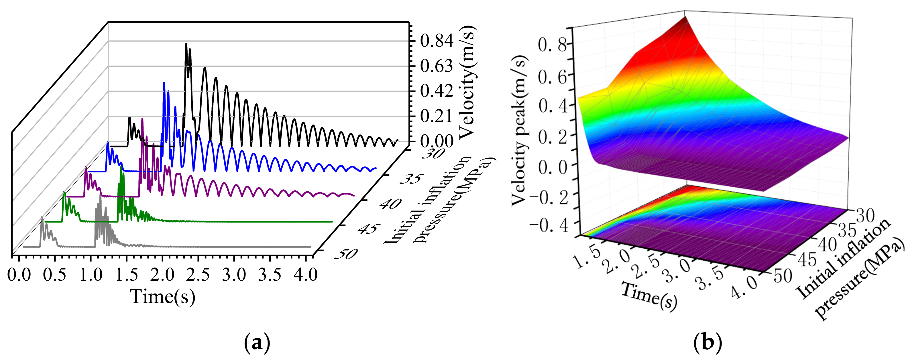
4.1. Influence of Initial Inflation Pressure of Buffer Cavity

The length of the buffer cavity was set to 105 mm, and the initial inflation pressure in the buffer cavity was set to 30, 35, 40, 45, and 50 MPa. The mechanical response and motion response characteristics of the novel balance jack under the same impact load were compared and analyzed.
Figure 9 is the force change diagram of the hinge point between the top beam and the balance jack when the front end of the top beam is subjected to rapid impact load. It can be seen from the figure that with the increase in the initial inflation pressure of the buffer cavity, the stable force of the hinge point decreases as a whole. When the initial inflation pressure of the buffer cavity is less than or equal to 45 Mpa, the lower the initial inflation pressure is, the force at the hinge point of the balance jack performs with larger fluctuation amplitude and lower frequency. Moreover, the lower initial inflation pressure also leads to the greater peak force at the hinge point and longer stabilization time for the balance jack. This is because the lower the initial inflation pressure is, the smaller the buffer force is, the easier the buffer cavity is compressed, and the worse the buffer effect is. When the initial inflation pressure of the buffer cavity is greater than 45 Mpa, the higher the initial inflation pressure is, the force at the hinge point of the balance jack performs with larger fluctuation amplitude and higher frequency. Moreover, the higher initial inflation pressure also leads to the greater peak force at the hinge point and shorter stabilization time for the balance jack. This is because the higher the initial inflation pressure is, the greater the buffer force is, and the buffer cavity is more difficult to be compressed, which cannot buffer effectively. From the point of view of force at the hinge point, when the length of buffer cavity is 105 mm, the initial inflation pressure is 40~45 Mpa, and the buffer effect is better. Therefore, reasonable that initial inflation pressure must be set according to the actual work requirements.
Figure 10 is the response diagram of the velocity and peak fitting of velocity fluctuation of the piston rod of the balance jack when the front end of the top beam is subjected to a rapid impact load. It can be seen from the figure that the lower the initial inflation pressure of the buffer cavity, the greater the maximum value of the piston rod speed is after impact, the lower the fluctuation frequency is and the longer the time to stabilize is. The reason is that the lower the initial inflation pressure of the buffer cavity is, the easier it is to be compressed, and the less energy absorbed appears in the buffer process. The lower the initial inflation pressure of the buffer chamber is, the slower the speed attenuation is, and the greater the peak value of the speed fluctuation is, the greater the inertia impact it receives, and the more likely it is to cause damage to the balance jack. The higher the initial inflation pressure of the buffer cavity, the higher the speed change frequency of the piston rod after impact. Moreover, the higher initial inflation pressure also leads to the higher impact frequency on itself and the connecting ear seat in a short time, which is more likely to cause damage to the balance jack and reduce its service life. Therefore, in order to reduce the impact on the balance jack as much as possible, the initial inflation pressure of the buffer chamber should not be too low or too high. In the data compared by this group of simulation, the initial inflation pressure is set at 40~45 MPa, which has a better buffer effect.
Figure 11a is schematic diagram of vertical displacement change in the centroid of top beam. Figure 11b is the response diagram of displacement change in vertical direction of the centroid of the top beam when the front end of the top beam is subjected to rapid impact load. It can be seen from the diagram that lower initial inflation pressure of the buffer cavity causes the vertical displacement of the top beam to have larger fluctuation amplitude and longer stabilization time. Moreover, the lower initial inflation pressure also leads to a greater change in the vertical displacement after stabilization and is more likely to cause the instability of the support. When the initial inflation pressure is low, the frequency difference of displacement change is small. When the initial inflation pressure is high, the displacement change frequency is significantly accelerated and can quickly reach stability. Therefore, in order to ensure the working stability of the support, the initial inflation pressure of the novel balance jack buffer cavity should not be less than 40 MPa.
Based on the above analysis, considering the force of the balance jack hinge point, the stability of the hydraulic support and the impact on itself, the initial inflation pressure of the buffer cavity was set to 40~45 MPa, and the buffer effect was better.

4.2. Influence of Length of Buffer Cavity

The initial inflation pressure in the buffer cavity was set to 40 MPa, and the length of the buffer cavity was set to 65, 85, 105, 125, and 145 mm. The mechanical response and motion response characteristics of the novel balance jack under the same impact load were compared and analyzed.
Figure 12 is the force change diagram of the hinge point between the top beam and the balance jack when the front end of the top beam is subjected to rapid impact load. It can be seen from the figure that with the increase in the length of the buffer cavity, the peak force and stable force of the hinge point increases as a whole. With the increase in the length of the buffer cavity, the fluctuation frequency is lower, and the time the balance jack needs to stabilize is longer. The reason is that when the initial inflation pressure of the buffer cavity is the same and the buffer cavity is compressed at the same distance, the shorter the initial length of the buffer cavity is, the greater the buffer force is, and the more energy absorbed in the buffer process is, the better the buffer effect is. Therefore, from the point of view of the force of the balance jack hinge point, the length of buffer cavity should be shortened as much as possible under the same initial inflation pressure of buffer cavity.
Figure 13 is the response diagram of the velocity and peak fitting of velocity fluctuation of the piston rod of the balance jack when the front end of the top beam is subjected to a rapid impact load. It can be seen from the figure that the longer the length of buffer cavity is, the greater the maximum velocity of the piston rod is, the lower the fluctuation frequency is, and the longer the time to stabilize is. The reason is that the initial charging pressure of the buffer cavity is the same. The longer the buffer cavity is, the smaller the equivalent force is generated under the same compression distance. The less the energy absorbed in the buffer process is, the easier it is to be compressed, and the worse the buffer effect is. The longer the buffer cavity length is, the slower the velocity attenuation is. At the same time, with the increase in buffer cavity length, the greater the peak velocity fluctuation is, the greater the inertial impact is, and the more likely it is to cause damage to the balance jack. In addition, when the length of buffer cavity is between 85 mm and 105 mm, the change rate of the maximum velocity of the piston rod is the largest. Therefore, in order to reduce the impact on the balance jack and achieve a better buffer effect, the buffer cavity length should be less than 105 mm.
Figure 14 is the response diagram of displacement change in vertical direction of the centroid of top beam when the front end of the top beam is subjected to rapid impact load. The figure shows that under the same initial inflation pressure, the buffer cavity length is longer, the vertical displacement of the top beam has larger fluctuation amplitude and lower frequency, and the time needed to stabilize is longer. Moreover, the longer buffer cavity length also leads to the greater the change in the vertical displacement after stabilization and is more likely to cause the instability of the support. Therefore, in order to ensure the working stability of the support, the length of buffer cavity should be shortened as much as possible under the same initial pressure.
Based on the above analysis, considering the force of the balance jack hinge point, the stability of the hydraulic support and the impact on itself, when the initial inflation pressure of the buffer cavity is 40~45 MPa and the length is less than 105 mm, the buffer effect is better.

5. Conclusions

In order to solve the problem that the balance jack easily to fails under frequent impact load and to improve the impact resistance of hydraulic support, an improved multi-adaptive response balance jack was proposed in this paper. The energy dissipation characteristics of the novel balance jack were analyzed, the mechanical response characteristics of the novel balance jack and the traditional balance jack under different impact loads were compared and analyzed, and the different influencing factors on the dynamic performance of the novel balance jack were discussed. The main conclusions are as follows:
(1)
By comparing and analyzing the mechanical response characteristics of the two kinds of balance jacks under different impact loads, it can be concluded that compared with the traditional balance jack, the novel balance jack with multi-adaptive response proposed in this paper can reduce the peak force of the hinge point by about 24.6%, and the fluctuation frequency was significantly reduced under the ultimate load condition at the front end of the top beam, which performs an effective buffer protection role;
(2)
When the high-pressure gas is used to buffer, with the decrease in the initial inflation pressure of the buffer cavity, the stable force of the hinge point increases, and the fluctuation of the piston rod velocity and the top beam vertical displacement is more violent. When the initial inflation pressure is less than or equal to 45 MPa, the lower the initial inflation pressure is, the greater the peak force of the hinge point is. When the initial inflation pressure is greater than 45 MPa, the higher the initial inflation pressure is, the greater the maximum force of the hinge point is;
(3)
When the high-pressure gas is used to buffer, with the increase in the length of the buffer cavity, the peak force and stable force of the hinge point increase, and the velocity of the piston rod and the vertical displacement of the top beam fluctuate more violently. When the initial inflation pressure of the buffer cavity is 40~45 MPa and the initial length of the buffer cavity is less than 105 mm, the buffer effect is better.
This novel type of balance jack with multi-adaptive responses performs effectively to resist impact pressure and reduce the failure rate of the balance jack, which is of great significance to improve the impact resistance of hydraulic support and ensure the working reliability of hydraulic support.

6. Patents

An Impact-Resistant Balanced Hydro-Cylinder with Pressure Relief and Buffering Protection.

Author Contributions

Conceptualization, L.W. and X.Y.; methodology, L.W.; software, X.Y. and Z.M.; validation, X.Y., D.M. and Q.Z.; formal analysis, X.Y. and G.Q.; writing—original draft preparation, X.Y.; writing—review and editing, L.W. and D.M.; simulation, X.Y.; funding acquisition, L.W. and Q.Z. All authors have read and agreed to the published version of the manuscript.

Funding

This research was funded by the National Natural Science Foundation of China, grant numbers 51974170 and 52104164, and the Natural Science Foundation of Shandong Province, grant number ZR2020QE103.

Institutional Review Board Statement

Not applicable.

Informed Consent Statement

Not applicable.

Data Availability Statement

Data were curated by the authors and are available upon request.

Conflicts of Interest

The authors declare no conflict of interest.

References

  1. Wan, L.; Wang, J.; Zeng, Q.; Ma, D.; Yu, X.; Meng, Z. Vibration Response Analysis of the Tail Beam of Hydraulic Support Impacted by Coal Gangue Particles with Different Shapes. ACS. Omega 2022, 7, 3656–3670. [Google Scholar] [CrossRef] [PubMed]
  2. Lin, J.; Yang, T.; Ni, K.; Han, C.; Ma, H.; Gao, A.; Xiao, C. Effects of Boundary Conditions on Stress Distribution of Hydraulic Support: A Simulation and Experimental Study. Adv. Mech. Eng. 2021, 13, 1–16. [Google Scholar] [CrossRef]
  3. Guan, E.; Miao, H.; Li, P.; Liu, J.; Zhao, Y. Dynamic Model Analysis of Hydraulic Support. Adv. Mech. Eng. 2019, 11, 1–8. [Google Scholar] [CrossRef] [Green Version]
  4. Cao, L.; Sun, S.; Zhang, Z.; Zhang, Y.; Guo, H.; Yan, M.; Guo, Z.; Zhong, C. Optimal design of balance jack control loop of hydraulic support. Ind. Mine Autom. 2018, 44, 13–18. [Google Scholar]
  5. Meng, Z.S.; Zhang, J.M.; Xie, Y.Y.; Lu, Z.G.; Zeng, Q.L. Analysis of the Force Response of a Double-Canopy Hydraulic Support under Impact Loads. Int. J. Simul. Model. 2021, 20, 766–777. [Google Scholar] [CrossRef]
  6. Ghorbani, M.; Shahriar, K.; Sharifzadeh, M.; Masoudi, R. A Critical Review on the Developments of Rock Support Systems in High Stress Ground Conditions. Int. J. Min. Sci. Technol. 2020, 30, 555–572. [Google Scholar] [CrossRef]
  7. Guo, W.; Wang, H.; Dong, G.; Li, L.; Huang, Y. A Case Study of Effective Support Working Resistance and Roof Support Technology in Thick Seam Fully-Mechanized Face Mining with Hard Roof Conditions. Sustainability 2017, 9, 935. [Google Scholar] [CrossRef] [Green Version]
  8. Świątek, J.; Janoszek, T.; Cichy, T.; Stoiński, K. Computational Fluid Dynamics Simulations for Investigation of the Damage Causes in Safety Elements of Powered Roof Supports—A Case Study. Energies 2021, 14, 1027. [Google Scholar] [CrossRef]
  9. Wang, J.; Zhang, J. Research on High-Power and High-Speed Hydraulic Impact Testing Machine for Mine Anti-Impact Support Equipment. Shock. Vib. 2019, 2019, 6545980. [Google Scholar] [CrossRef] [Green Version]
  10. Szurgacz, D.; Brodny, J. Analysis of Load of a Powered Roof Support’s Hydraulic Leg. E3S Web Conf. 2018, 71, 2. [Google Scholar] [CrossRef] [Green Version]
  11. Singh, G.S.P.; Singh, U.K. A Numerical Modeling Approach for Assessment of Progressive Caving of Strata and Performance of Hydraulic Powered Support in Longwall Workings. Comput. Geotech. 2009, 36, 1142–1156. [Google Scholar] [CrossRef]
  12. Verma, A.K.; Deb, D. Numerical Analysis of an Interaction between Hydraulic-Powered Support and Surrounding Rock Strata. Int. J. Geomech. 2013, 13, 181–192. [Google Scholar] [CrossRef]
  13. Shabanimashcool, M.; Jing, L.; Li, C.C. Discontinuous Modelling of Stratum Cave-in in a Longwall Coal Mine in the Arctic Area. Geotech. Geol. Eng. 2014, 32, 1239–1252. [Google Scholar] [CrossRef]
  14. Pytlik, A. Process Characteristics of Hydraulic Legs Equipped with Safety Valves at Dynamic Load Caused by a Mining Tremor. Arch. Min. Sci. 2015, 60, 595–612. [Google Scholar] [CrossRef] [Green Version]
  15. Szurgacz, D.; Brodny, J. Analysis of the Influence of Dynamic Load on the Work Parameters of a Powered Roof Support’s Hydraulic Leg. Sustainability 2019, 11, 2570. [Google Scholar] [CrossRef] [Green Version]
  16. Szurgacz, D. Dynamic Analysis for the Hydraulic Leg Power of a Powered Roof Support. Energies 2021, 14, 5715. [Google Scholar] [CrossRef]
  17. Liu, X.; Zhao, Z.; Zhao, R. Study on Dynamic Features of Leg Applied to Hydraulic Powered Support Under Bumping Load. Coal Sci. Technol. 2012, 40, 66–70. [Google Scholar] [CrossRef]
  18. Wan, L.; Liu, P.; Meng, Z.; Lu, Y. Analysis of the influence of impact load on shield beam of hydraulic support. J. China Coal Soc. 2017, 42, 2462–2467. [Google Scholar] [CrossRef]
  19. Zeng, X.T.; Meng, G.Y.; Zhou, J.H. Analysis on the Pose and Dynamic Response of Hydraulic Support Under Dual Impact Loads. Int. J. Simul. Model 2018, 17, 69–80. [Google Scholar] [CrossRef]
  20. Yang, Z.K.; Sun, Z.Y.; Jiang, S.B.; Mao, Q.H.; Liu, P.; Xu, C.Z. Structural Analysis on Impact-Mechanical Properties of Ultra-High Hydraulic Support. Int. J. Simul. Model. 2020, 19, 17–28. [Google Scholar] [CrossRef]
  21. Yang, P.; Liu, C.; Jin, T. Research on the Load Variation Laws and Technologic Effect of Two-Leg Sublevel Caving Shield Support. J. Minging Saf. Eng. 2010, 27, 512–516. [Google Scholar]
  22. Li, H.; Jiang, D.; Peng, S.S.; Feng, J. Analysis on loading features and suitability of hydraulic powered caving supports. Coal Sci. Technol. 2015, 43, 23–28 + 70. [Google Scholar]
  23. Li, J. Analysis on Mining Method and Roof Stability under Condition of Transform from Large Height Mining to Top Coal Mining. Ph. D. Thesis, China University of Mining and Technology, Beijing, China, 2014. [Google Scholar]
  24. Xu, Y.; Wang, G.; Liu, Y. Supporting property and adaptability of 2-leg powered support. J. China Coal Soc. 2016, 41, 2113–2120. [Google Scholar]
  25. Liang, L.C.; Tian, J.J.; Zheng, H.; Jiao, S.J. A Study on Force Transmission in a Hydraulic Support under Impact Loading on Its Canopy Beam. J. China Coal Soc. 2015, 40, 2522–2527. [Google Scholar] [CrossRef]
  26. Zeng, Q.; Yang, C.; Liu, P.; Meng, Z. Stress Analysis of Hydraulic Powered Support for Ultra High Mining under Different Roof Pressure. Coal Technol. 2018, 37, 187–189. [Google Scholar] [CrossRef]
  27. Zeng, Q.; Meng, Z.; Wan, L.; Wang, C. Analysis on Force Transmission Characteristics of Two-Legged Shield Support under Impact Loading. Shock Vib. 2018, 2018, 3854684. [Google Scholar] [CrossRef] [Green Version]
  28. Meng, Z.; Zeng, Q.; Gao, K.; Kong, S.; Liu, P.; Wan, L. Failure Analysis of Super-Large Mining Height Powered Support. Eng. Fail. Anal. 2018, 92, 378–391. [Google Scholar] [CrossRef]
  29. Wang, G. Design of mechanical limiting device for top beam of two-column shield hydraulic support. Coal Mine Mach. 1991, 5, 7–10. [Google Scholar]
  30. Shang, H. Failure Analysis and Prevention of Equilibrium Jack on Hydraulic Shield Support. Colliery Mech. Electr. Technol. 2011, 5, 88–91. [Google Scholar]
  31. Sun, Y.; Zhneg, X.; Lin, X.; Hu, J. Research on Hydraulic Circuit Optimization of Hydraulic Support Balance Jack Based on AMESim. Coal Mine Mach. 2020, 41, 156–158. [Google Scholar]
  32. Wan, L.R.; Yu, X.H.; Ma, D.J.; Wang, J.T.; Xin, F.W.; Li, Z.J.; Qi, G.Q.; Chen, B.L. Impact-Resistant Balanced Hydro-Cylinder with Pressure Relief and Buffering Protection. CN112555228B, 5 November 2021. [Google Scholar]
  33. Wang, W.; Zhou, R. Impact of Gas Spring on Dynamic Characteristics of Safety Valve. Chin. Hydraul. Pneum. 2014, 8, 111–114. [Google Scholar]
Figure 1. Actual failure mode: (a) hydraulic support; (b) the balance jack; (c) damage at the connection of piston rod; (d) piston rod bending; (e) the coupling pin shaft is broken; (f) pin hole deformation.
Energies 15 05236 g001
Figure 2. Structure comparison of the balance jack: (a) the traditional balance jack; (b) the multi-adaptive response balance jack. 1. cylinder body; 2. piston rod; 3. rodless cavity buffer cavity; 4. rodless cavity unloading hole; 5. rodless cavity floating piston; 6. Rod cavity unloading hole; 7. rod cavity floating piston; 8. rod cavity buffer cavity; 9. 12 limit boss; 10. 11 oil cavity.
Energies 15 05236 g002
Figure 3. Schematic diagram of buffer process of multi-adaptive response balance jack.
Energies 15 05236 g003
Figure 4. Simulation model diagram: (a) simulation model of hydraulic support with the traditional balance jack; (b) simulation model of hydraulic support with the novel balance jack.
Energies 15 05236 g004
Figure 5. The equivalent schematic diagram: (a) column; (b) the traditional balance jack; (c) the novel balance jack with multi-adaptive response.
Energies 15 05236 g005
Figure 6. The stable working state diagram of the support under 14,000 kN load.
Energies 15 05236 g006
Figure 7. Force at hinge point: (a) The hinge point of top beam-balance jack. (b) The hinge point of shield beam-balance jack.
Energies 15 05236 g007
Figure 8. Force at hinge point: (a) The hinge point of top beam-balance jack. (b) Hinge point of shield beam-balance jack.
Energies 15 05236 g008
Figure 9. (a) The force comparison of hinge point between top beam and the balance jack. (b) Peak force and stable force of hinge point.
Energies 15 05236 g009
Figure 10. (a) Speed comparison of piston rod. (b) Peak fitting of velocity fluctuation.
Energies 15 05236 g010
Figure 11. (a) Schematic diagram of vertical displacement change in the centroid of top beam. (b) Displacement change in vertical direction of the centroid of top beam.
Energies 15 05236 g011
Figure 12. (a) The force comparison of hinge point between top beam and the balance jack. (b) Peak force and stable force of hinge point.
Energies 15 05236 g012
Figure 13. (a) Speed comparison of piston rod. (b) Peak fitting of velocity fluctuation.
Energies 15 05236 g013
Figure 14. Displacement change in vertical direction of the centroid of top beam.
Energies 15 05236 g014
Table 1. Main parameters of column and the balance jack when the support height is 6.65 m.
CylinderOuter Diameter/mmInner Diameter/mmEffective Length of Liquid Column/mmBuffer Cavity Length/mm
The balance jack320230Rod Cavity567105
Rodless Cavity288105
ColumnFirst stage6255302113
Second stage500380775
Publisher’s Note: MDPI stays neutral with regard to jurisdictional claims in published maps and institutional affiliations.

