Article

Effect of In-Situ Stress on Hydraulic Fracturing of Tight Sandstone Based on Discrete Element Method

1
North China University of Water Resources and Electric Power, Zhengzhou 450045, China
2
Key Laboratory of Geological Environment Intelligent Monitoring and Disaster Prevention and Control of Henan Province, Zhengzhou 450045, China
3
SCIVIC Engineering Corporation, Luoyang 471000, China
*
Authors to whom correspondence should be addressed.
Energies 2022, 15(15), 5620; https://doi.org/10.3390/en15155620
Submission received: 2 June 2022 / Revised: 13 July 2022 / Accepted: 25 July 2022 / Published: 3 August 2022

Abstract

:
The tight sandstone reservoir in the Qianfoya formation of well PL-3 of the Puguang gas field in Sichuan, China, obtained a high-yield gas flow after a volume fracturing treatment. However, the stimulated reservoir volume (SRV), fracture morphology, scale and formation law still remain unclear. Based on particle flow discrete-element theory in this paper, we carried out a few trials of the Brazilian splitting test, uniaxial compression and triaxial compression of rock mechanics. Meanwhile, the research also testified to the conversion relationship between macroparameters and microparameters, established the numerical simulation on hydraulic fracturing through PFC2D discrete element software, and finally analyzed the influence of difference coefficients on the fracturing effect, in terms of different in-situ stresses. The conclusions are as follows: firstly, the influence of in-situ stress is essential for the direction, shape and quantity of fracture propagation, and the fractures generated by hydraulic fracturing are mainly tension fractures, accounting for over 90% of the total longitudinal fractures. Secondly, it is indicated that when the difference coefficient is small in the in-situ stress, the fractures formed by hydraulic fracturing expand randomly around the wellbore. When the difference coefficient Kh of in-situ stress is above 0.6, the development of hydraulic fractures is mainly controlled by in-situ stress; as a result, the fractures tend to expand in the vertical direction of the minimum horizontal principal stress and the fracture shape is relatively singular. When the difference coefficient of in-situ stress was 0.3, in total, 3121 fractures were generated by fracturing, and the fractal dimension D value of the fracture network complexity was 1.60. In this case, this fracturing effect was the best and it is the easiest to achieve for the purpose of economical and effective development on large-scale volume fracturing.

1. Introduction

Rock from the Jurassic period is the main stratum in the continental tight gas reservoir in the Sichuan Basin. Through the analysis and evaluation of the previous data, it was found that the resources of the four favorable sand formations in the Qianfoya formation totaled 123.4 billion cubic meters [1]. Tight sandstone gas is a typical unconventional natural gas resource stored in tight sandstone reservoirs with ultra-low permeability, which is difficult to exploit with conventional technology. In this case, large-scale fracturing or special gas extraction technology is essential to produce the valuable natural gas. Tight sandstone, with shale gas and coal bed methane (CBM), are considered as three major unconventional natural gases [2]. Among these three types of unconventional gas, tight sandstone gas is known as the first gas which has contributed to the most rapid growth of natural gas production and reserves in China [3,4,5]. Large-scale hydraulic fracturing technology is the core technique for achieving the commercial advancement of tight sandstone gas. The existing foreign fracturing technologies are as follows [6,7,8,9]: (1) Nitrogen foam fracturing technology, which originated in January 1968, has been widely used in the United States and Canada. It is especially applicable to water-sensitive formations with low pressure and low permeability [6]; (2) Clear water fracturing technology uses clear water to add an appropriate drag-reducing agent as the fracturing fluid, thus saving 30% of the cost without dampening production. Moreover, the sound application effect has been shown in the reconstruction of low permeability oil–gas reservoirs [7]; (3) Simultaneous fracturing technology. As the latest fracturing technology, it has been successfully applied at the Barnett tight gas development in the Fort Worth Basin in recent years. It is able to fracture two (or more) wells simultaneously [8]. For example, the Tipton-1H-23 well, located in the Woodford tight gas accumulation zone of the Arkema Basin in the United States, has been transformed by seven stages of hydraulic fracturing, and the unconventional gas production is as high as 14.16 × 10⁴ m3/d [9].
Over the past few decades, a series of laboratory experiments have been carried out to explore the failure process of reservoir rocks [10]. When dealing with some simple problems, the developed Perkins–Kern–Nordgren model (PKN) [11,12] and the Khristianovic– Geertsma–de Klerk model (KGD) [13,14] can be used.
Ito et al. [15] developed an experimental apparatus for observing the hydraulic fracture on the X-ray CT scanning. The results clearly showed the characteristic behaviors of the hydraulic fracture in the rock matrix. Chitrala [16] combined analysis of acoustic emission (AE) systems to study the hydraulic fracture propagation in Lyons sandstone under different stress conditions. He et al. [17] conducted a series of hydraulic fracturing experiments on cylinder sandstone cores with a central borehole. Using microscope and X-ray CT scanning, the fracture morphology of the surfaces and internal structure of the fractured specimens were acquired, respectively. Wang et al. [18] studied the effect of bedding orientation on the fracture toughness of rock. The study is of great significance for analyzing rock fracture characteristics.
As an intuitive and practical method to study the mechanism and formation of hydraulic fractures, numerical simulation provides a better visual means for observing the fracture geometry with better controlling conditions. Zhang et al. [19] conducted multiscale numerical analysis on fully coupled hydraulic fracturing to study some of the key coupled processes of fluid-driven fracture propagation in naturally fractured rock masses. V. Roche et al. [20] investigated the hydraulic fracture development and its potential impact on elastic stress perturbations and fracture triggering. In intact granite and homogeneous granite with cracks, the fully coupled hydrodynamic 3D discrete-element method was used to simulate the hydraulic cracks during fluid injection. Savitsk et al. [21] presented the most advanced modeling results of the explicit interaction between extended hydraulic fractures and discrete fracture networks, which were statistically generated. Damjanac et al. [22] proposed a synthetic rock mass (SRM) concept. In SRM, the bonded particle model (BPM) is a collection of circular or spherical particles bonded to each other, indicating the deformation and damage in intact rock. If pre-existing discontinuities are represented in the BPM, the generated model, referred to as SRM, is able to simulate hydraulic fracturing in naturally fractured reservoirs [23,24,25]. The pump displacement has a significant impact on the fracturing effect, especially for the transformation of unconventional reservoirs [26,27]. Numerous researchers have analyzed the fracturing displacement design for many times, thus obtaining a great number of conclusions that can be used for reference in engineering. The optimized construction design not only ensures the full transformation of tight reservoirs, but also avoids waste from injecting excess fracturing fluid [28,29].

2. Sandstone Rock Mechanical Parameter Testing

2.1. Experiment System

The testing machine, as shown in Figure 1a, had an independent closed-loop servo control system for axial pressure, confining pressure, pore water pressure and temperature. The main machine adopted a gate-post structure with the 2000 kN axial pressure and 100 MPa confining pressure, which is tougher than 10 GN/M. The pore water pressure was 60 MPa, with a temperature of −50–200 °C; in addition, the diameter of the specimen was 25 mm–100 mm, and the minimum intervals of sampling were 20 ms. The machine can carry out uniaxial and triaxial stress–strain tests in the whole process, including constant speed, variable speed, cyclic loading and unloading and various waveform control tests, as well as pore water and characteristic tests under both high and low temperatures, etc. During the test, displacement sensors were used to measure the axial and circumferential deformation of the test piece. The circumferential deformation was measured with a circumferential point extensometer. The software measurement and control system are shown in Figure 1b.

2.2. Experimental Scheme and Test Results

The specimens were taken from well PL-3 of the Puguang east syncline structure, which is located in the Huangjinkou structural belt of the Sichuan Basin. The measured depth (MD) was 3979.00 m and the true vertical depth (TVD) was 3282.64 m. The drilled layer was Middle Jurassic. The core section was 3408 m high. Before the test, we prepared standard cylindrical specimens with 25 mm diameter, and 50 mm height, along with standard Brazilian disk specimens with a diameter of 25 mm and a height of 25 mm. The test results are shown in Table 1. The average tensile strength of the sandstone was 14.73 MPa, the elastic modulus without confining pressure was 33.55 GPa, and Poisson’s ratio was 0.051. Triaxial compressive mechanical tests were carried out under confining pressures of 5 MPa, 10 MPa and 20 MPa, and the Mohr-stress circle and shearing strength envelope were drawn. The sandstone cohesion c was calculated to be 43.05 MPa, and the internal friction angle φ was 42.8°.

3. Numerical Analysis of Hydraulic Fracturing Based on Discrete Element Method

3.1. Microparameter Calibration

Particle Flow Code 2D software was used for numerical simulation [30]. The particle bond model and smooth joint model were used to characterize the complete rock block and joint surface, respectively; meanwhile, the hydraulic fracturing numerical simulation and comparative analysis were carried out on the intact rock and the fractured rock mass. Potyondy et al. used the BPM model (bonded-particle model) to simulate the mechanical behavior of Lac du Bonnet granite [31]. Particle contacts are bonded with limited strength at the points of contact and limited thickness around the points of contact so that the bond can resist tensile loading, shear loading and moment using the enhanced parallel-bonding model [32,33,34]. The smooth-joint model with the behavior of dilated planar interface was used to embed pre-existing cracks regardless of the local particle contact orientation at the interface. Modeling the behavior of a frictional or bonded joint can be achieved by assigning smooth-joint models to all contacts among particles on opposite sides of the joint [35].
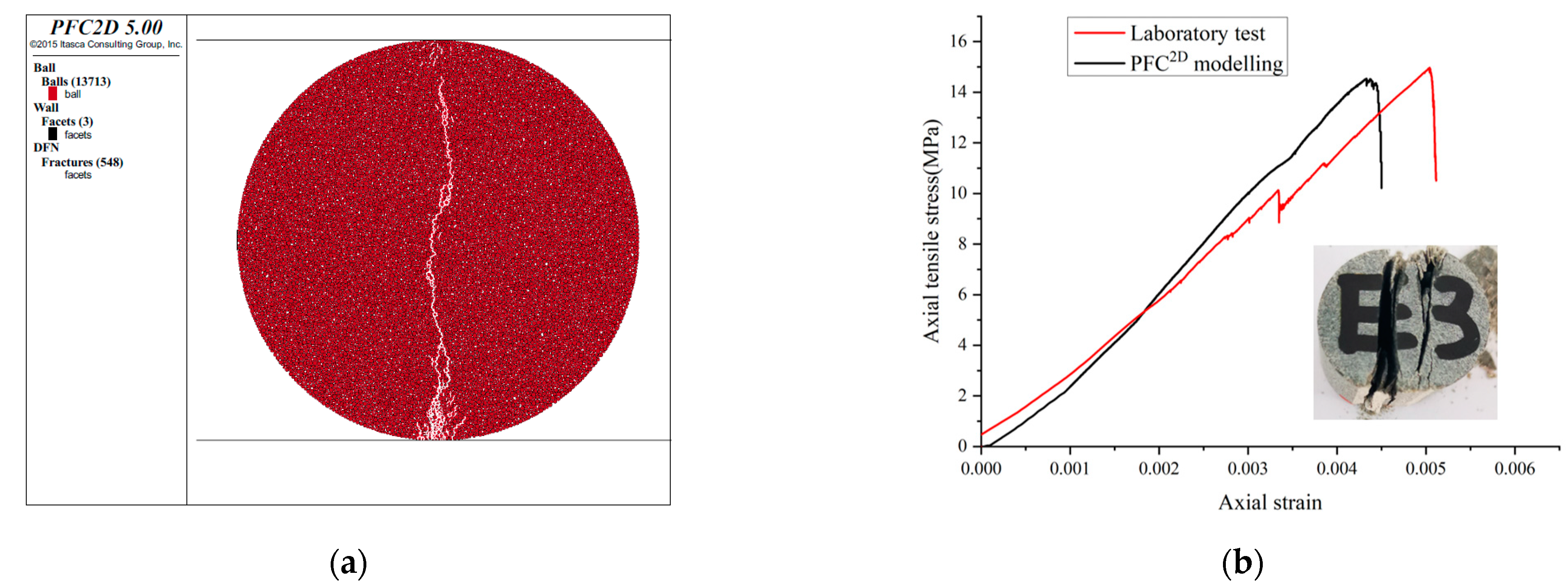
The specimens were tested on a TAW-2000 electro-hydraulic servo rock mechanic system for the detection of uniaxial tensile strength σt, compressive strength σf, Poisson’s ratio ν and elastic modulus E. Each test contained four specimens, with the final results averaged (Table 1). Sandstone PFC2D models (Figure 2) for numerical test on uniaxial compression and indirect tensile were established with a smooth-joint contact model since the contact model was used to calculate the macroparameters. The specified loading rate for the compression test and direct tension test was “0.06 m/s”. Table 2 shows the microscopic properties of the smooth-joint contact model calibrated by simulating the compression and tension test (Figure 2 and Figure 3). The numerical and experimental results of the synthetic rock specimens were basically consistent with each other.

3.2. Fluid-Mechanical Coupling Theory of PFC2D

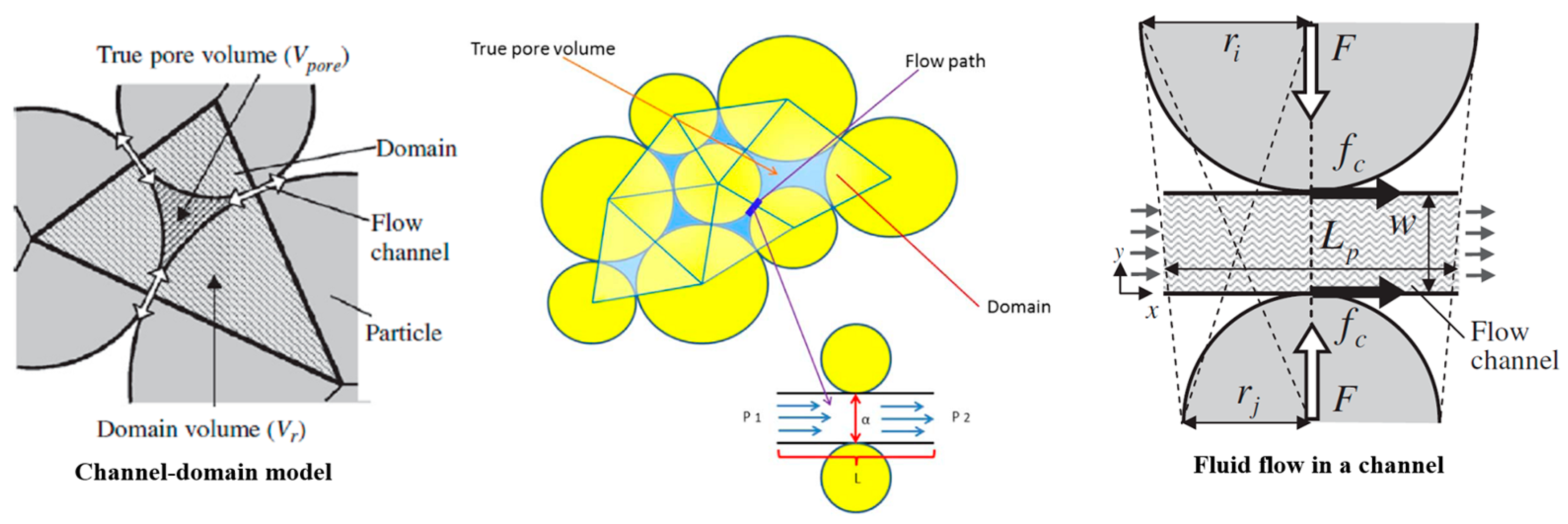
When simulating the coupling between the stress field and the seepage field of a jointed rock mass, those two fields should be taken into consideration at the same time. The seepage effect can be modeled using a fluid “domain” and fluid “pipe”. A “domain” is defined as a closed chain of particles, where each link in the chain is a bonded contact. Each domain has a pointer through which all domains are connected [30]. As shown in Figure 4, each channel is assumed to be a set of parallel plates with a certain aperture, and the fluid flow in the channel is modeled with the Poiseuille equation. The fluid flow rate q is given by the following equation:
q = a 3 × Δ p 12 μ × L
where a is the aperture, Δp is the fluid pressure difference between the adjacent domains, Δp = p2p1, p2 and p1 are pressures inside the two connected domains (inlet and outlet), μ is the fluid viscosity, and L is the length of the channel. The out-of-plane thickness is assumed to be unit length.
In order to ensure that aperture a will approach zero-force aperture when the normal-contact force is zero and converges to zero, in the situation where the normal-contact force is quite large, the following equation can be used [37,38]:
a = a 0 F 0 n F n + F 0 n
where Fn is the normal contact force, a0 is assumed to be the initial aperture of just-touching particles and F 0 n is the normal force at which the channel aperture reduces to half of its initial aperture.

3.3. Sandstone Models for Hydraulic Fracturing

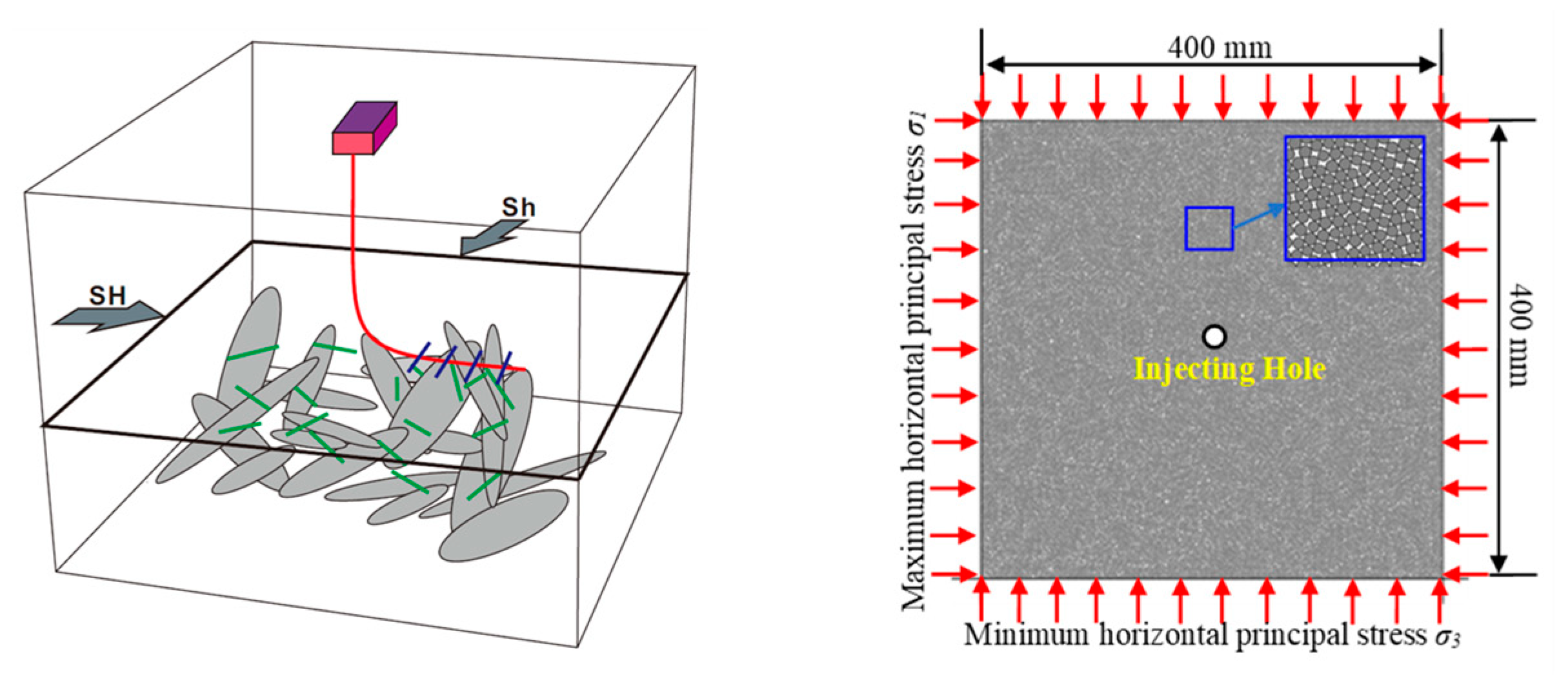
The study focuses on the initiation and propagation of hydraulic fracturing affected by the in-situ stress difference coefficient (SDC) and natural fractures [39]. The size of the model was 400 mm × 400 mm. The particles in the model were uniformly distributed, and radius R ranged from Rmin (minimum of particle radius) to Rmax (maximum of particle radius). The Rmin was 2 mm, the ratio of particles ranging from the maximum to the minimum radius was 1.66. Some 24,808 particles were generated in the square model. The particle-filled square assembly was enclosed by four servo-controlled walls that allowed the initial stresses to be executed. The calculation model was constructed, as shown in Figure 5. The intact rock was represented by the bonded particle model (BPM), and pre-existing natural cracks were simulated by the smooth-joint model (SJM) [30].

4. Influence of In-Situ Stress Difference Coefficient on Hydraulic Fracturing Effect

In-situ stress is the natural stress existing in the crust, mainly composed of the self-weight stress of rock mass and the tectonic stress caused by the geological structure [40]. In-situ stress is the main reason for deformation and instability on underground or slope engineering. Therefore, the in-situ stress measurement is a prerequisite for disaster control. It is very important to understand the influencing factors of in-situ stress, including the structural characteristics of rock–soil mass, physical and mechanical properties, space–time conditions, etc. [41,42]. With the progress of human civilization, the demand for deep resources continues to surge; deep mining has also become a major problem for the engineering community. As a result, the in-situ stress is playing a more and more essential role in the safe construction and long-term stability of underground engineering. Therefore, the accurate measurement of in-situ stress has become the critical point to solve the problem effectively. The effect of in-situ stress on fracture morphology is mainly reflected in the size of horizontal principal stress difference, and the influence of the horizontal principal stress difference on fracture morphology is determined by the horizontal stress difference coefficient Kh [43]. This parameter is defined as [44,45]:
K h = σ H σ h σ h × 100 %
where σH is the maximum horizontal principal stress (MPa), and σh is the minimum horizontal principal stress (MPa).
When the maximum horizontal principal stress σH and the minimum horizontal principal stress σh are both 10 MPa, the horizontal in-situ stress difference coefficient Kh = 0. When the maximum horizontal principal stress σH = 11 MPa and the minimum horizontal principal stress σh = 10 MPa, the horizontal in-situ stress difference coefficient Kh = 10%. The horizontal difference coefficients of in-situ stress have been designed as 0, 10, 20, 30, 40, 50, 60, 70, 80, 90, and 100%, as shown in Table 3.
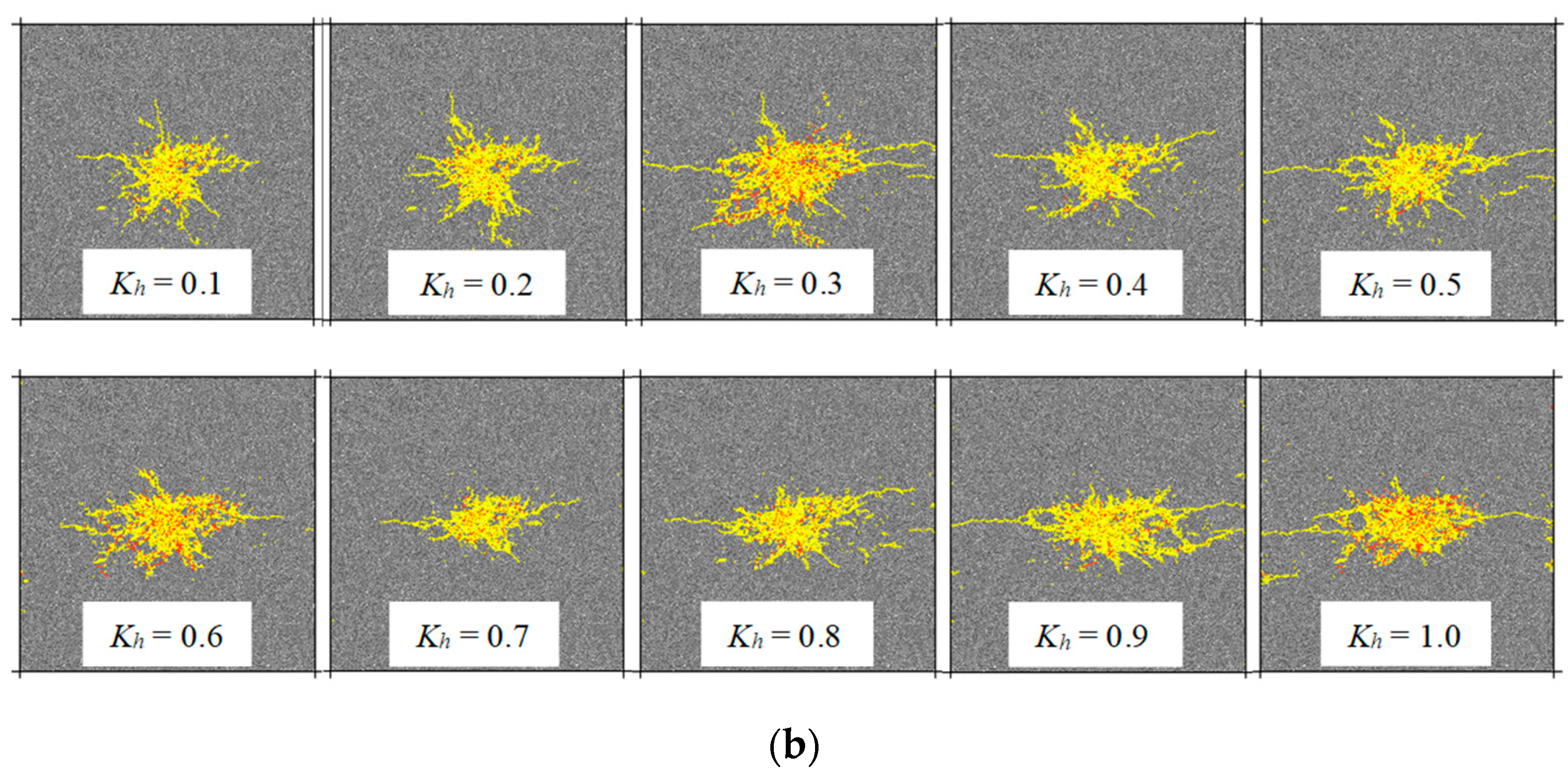
The wellbore injection construction pressure is 120 MPa, the reservoir permeability is 0.1 millidarcy, and the liquid viscosity μ = 10 mP.s. Figure 6a shows the fracturing network morphology at different time-steps when the horizontal in-situ stress difference coefficient Kh = 0: (1) When the numerical calculation time-steps were 20,000, 1419 fractures had been produced during fracturing, including 1131 tension fractures (yellow line represents tension fracture) and 288 shear fractures (red line represents shear fracture). Large quantities of fractures were concentrated around the wellbore, with an inconspicuous regularity of fracture trend; (2) When the numerical calculation time-steps were 40,000, 60,000, 80,000, and 100,000, respectively, the number of fractures generated by fracturing was 2019, 2414, 2798, and 3240, accordingly. Fractures gradually extended outward after initiation around the wellbore. Comparing the number of hydraulic fracturing fractures at different time-steps, it was found that the largest number of fractures emerged in the initial stage of fracturing fluid pumping with a higher degree of fracture concentration. As the fracturing fluid was continuously pumped into the wellbore, the inefficiency of the hydraulic fracturing was seen in generating the fractures, and the fractures expanded from disorder to the extension of several main fractures. At the same time, it was noticeable that the area of hydraulic fracturing increased rapidly due to the expansion of the main fractures in all four directions. Figure 6b shows the fracturing network morphology under different horizontal difference coefficients of in-situ stress: when the horizontal in-situ stress difference coefficient Kh was between 0 and 0.2, the fractures formed by hydraulic fracturing randomly spread around the wellbore. When Kh was between 0.3 and 0.6, the fractures formed by fracturing not only expanded randomly around the wellbore, but also gradually formed main cracks along the direction of the maximum principal stress, and the control effect of in-situ stress was gradually enhanced. When the stress difference coefficient Kh was greater than 0.6, the development of hydraulic fractures was mainly controlled by the in-situ stress, the fractures expanded along the vertical minimum horizontal principal stress direction, and the fracture shape was relatively simple.
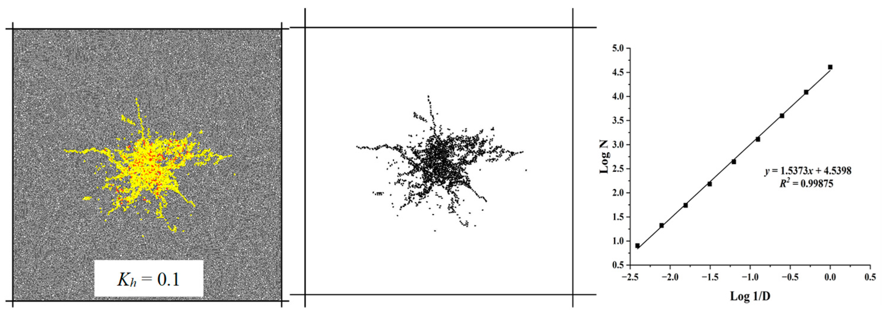
The fractal dimension value D of the fracture structure surface can be introduced to evaluate the complexity of fracturing fractures quantitatively. The box dimension calculation method is used to calculate the fractal dimension of the surface cracks in specimen, and the number of boxes of fractures contained in different scale grids on the structure surface is divided into [46]:
l g N ( δ ) = l g A D l g δ
where δ is the side length, A is the initial value of the fracture surface distribution, and D is the fractal dimension of the fracture distribution.
The basic steps are as follows: using a square grid with side length δ to cover the entire structural surface, and counting the number of grids containing cracks. Then using the bisection to decrease the side length δ of the square grid and counting the corresponding N(δ), and the least squares method is used to perform regression analysis on the statistical data in the double logarithmic coordinate system. The slope of the straight line is the fractal dimension D of the structural surface crack.
The fracture distribution is binarized by MATLAB software, and the fractal dimension D value of the fracture surface is introduced to evaluate the complexity of fracturing fractures quantitatively, which solves the problem of the quantitative evaluation on the stimulation effect of tight reservoirs. As shown in Figure 7, when the in-situ stress difference coefficient Kh = 0.1, the obtained fractal dimension index of the fracture network was 1.5373, as shown in Table 3. For continental tight sandstone with good homogeneity, two aspects of construction cost and fracturing effect should be considered. When the in-situ stress difference coefficient is 0.3, the maximum number of fractures generated by fracturing is 3121. In addition to the main fractures along the direction of the maximum principal stress, secondary fractures are also relatively developed. The fractal dimension D value of fracture network complexity is 1.60 and the fracture pressure is 43.73 MPa. In this case, the fracturing showed the most effective result; the fracture pressure is rarely high, and it is easier for large-scale volume fracturing to achieve economical and effective development. Figure 8 shows the evolution curve of fluid pressure–time–step at the injection point, the right picture is the curve enlarged by the red dotted line box in the left picture, point A (120, 43.06) is the fracture pressure point, and the fracture pressure is 43.06 MPa. After reaching the peak point, the wellbore pressure drops sharply to about 40 MPa, and then fluctuates sharply, indicating that the fractures are expanding and extending with a rough fracture surface to some extent.

5. Discussion

In this paper, numerical simulation on hydraulic fracturing was established by PFC2D discrete element software through a laboratory Brazilian splitting test, along with the test on uniaxial compression and triaxial compression rock mechanics. The influence of the fracturing effect from difference coefficients of different in-situ stresses was analyzed. In order to study the influence of a single factor (in-situ stress) on the fracturing effect of the tight sandstone of the Qianfoya formation, the numerical calculation model was intended to be homogeneous and isotropic, and the influence of natural sandstone fractures on the fracturing effect was not considered. The natural fractures are normally contained in the sandstone formations, and it is believed that the complexity of the resulting hydraulic-fracture network is caused by the interaction between the hydraulic fracture and natural fractures. Therefore, the authors and team members will further explore the structural effects of the hydraulic fracture network evolution in the later studies.

6. Conclusions

Based on the particle flow discrete-element theory, we checked the conversion relationship between macroparameters and microparameters, established numerical simulation on hydraulic fracturing by PFC2D discrete element software, and finally analyzed the influence of the fracturing effect from the difference coefficients on the different in-situ stresses. The following conclusions can be drawn:
(1)
The influence of in-situ stress on the direction, shape and quantity of fracture propagation is quite crucial, and the fractures generated by hydraulic fracturing are mainly tension fractures, accounting for more than 90% of total longitudinal fractures.
(2)
When the in-situ stress difference coefficient is small, the fractures gradually extend and expand outwards after the initiation of fracturing around the wellbore. The largest number of fractures emerge in the initial stage of pumping the fracturing fluid, with a higher degree of fracture concentration. As the fracturing fluid is continuously pumped into the wellbore, the inefficiency of the hydraulic fracturing can be seen when generating the fractures, and the fractures expand from disorder to the extension of several main fractures.
(3)
When the horizontal in-situ stress difference coefficient Kh is between 0 and 0.2, the fractures formed by hydraulic fracturing randomly expand around the wellbore. When Kh is between 0.3 and 0.6, the fractures form by fracturing gradually and expanding along the main crack in the direction of the maximum principal stress. When the stress difference coefficient Kh is above 0.6, the development of hydraulic fractures is mainly controlled by the in-situ stress; the fractures expand along the minimum horizontal principal stress in the vertical direction, leading to a relatively singular fracture shape.
(4)
As for the continental tight sandstone with good homogeneity, two aspects of construction cost and fracturing effect should be considered. When the local stress difference coefficient is 0.3, the maximum number of fractures generated by fracturing is 3121, and the main fractures along the direction of the maximum principal stress are generated, in relation to the development of secondary fractures. The fractal dimension D value of the fracture network complexity is 1.60 and the fracture pressure is 43.73 MPa; in this case, the fracturing shows the most effective result. The lower fracture pressure is more accessible for fracturing in large-scale volume to achieve economical and effective development.

Author Contributions

Conceptualization, H.W.; formal analysis, Y.S.; project administration, Y.W.; software, J.Z.; supervision, X.W.; writing—original draft, H.W. and W.G.; writing—review and editing, G.Y. All authors have read and agreed to the published version of the manuscript.

Funding

This research received no external funding.

Institutional Review Board Statement

Not applicable.

Informed Consent Statement

Not applicable.

Data Availability Statement

Not applicable.

Acknowledgments

This work was financially supported by the National Natural Science Foundation of China (41807254), China Postdoctoral Science Foundation (2020M682372), Young Talent Support Project of Henan Province (2021HYTP013), the Key Research & Development and promotion projects of Henan Province (No. 212102310374), Key scientific research projects of colleges in Henan province (20A410001), Second Tibetan Plateau Scientific Expedition and Research Program (STEP) (2019QZKK0904).

Conflicts of Interest

The authors declare no conflict of interest.

References

  1. Zou, C.; Zhu, R.; Wu, S.; Yang, Z.; Tao, S.; Yuan, X.; Hou, L.; Yang, H.; Xu, C.; Li, D.; et al. Types, characteristics, genesis and prospects of conventional and unconventional hydrocarbon accumulations: Taking tight oil and tight gas in China as an instance. Acta Pet. Sin. 2012, 33, 173–187. [Google Scholar] [CrossRef]
  2. Holditch, S.A. Tight gas sands. J. Pet. Technol. 2006, 58, 86–93. [Google Scholar] [CrossRef]
  3. Matthews, H.L.; Schein, G.W.; Malone, M.R. Stimulation of gas shales: They’re all the same-right. In Proceedings of the SPE Hydraulic Fracturing Technology Conference, College Station, TX, USA, 29–31 January 2007. [Google Scholar]
  4. Chong, K.K.; Grieser, B.; Jaripatke, O.; Passman, A. A completions roadmap to shale-play development: A review of successful approaches toward shale-play stimulation in the last two decades. In Proceedings of the International Oil and Gas Conference and Exhibition in China, Beijing, China, 8–20 June 2010. [Google Scholar]
  5. Mutalik, P.N.; Gibson, R.W. Case history of sequential and simultaneous fracturing of the Barnett Shale in parker county. In Proceedings of the SPE Annual Technical Conference and Exhibition, Denver, CO, USA, 21–24 September 2008. [Google Scholar]
  6. White, J.; Read, R. The shale shaker. Oil Gas Investor 2007, 47, 2–9. [Google Scholar]
  7. Vassilellis, G.D.; LI, C.; Seager, R.; Moos, D. Investigating the expected long-term production performance of shale reservoirs. In Proceedings of the Canadian Unconventional Resources and International Petroleum Conference, Calgary, AB, Canada, 19–21 October 2010. [Google Scholar]
  8. Maxwell, S.C.; Urbancic, T.I.; Steinsberger, N.; Zinno, R. Microseismic imaging of hydraulic fracture complexity in the Barnett Shale. In Proceedings of the SPE Annual Technical Conference and Exhibition, San Antonio, TX, USA, 29 September–1 October 2002. [Google Scholar]
  9. Kennedy, R.L.; Knecht, W.N.; Georgi, D.T. Comparisons and contrasts of shale gas and tight gas developments, North American experience and trends. In Proceedings of the SPE Saudi Arabia Section Technical Symposium and Exhibition, Al-Khobar, Saudi Arabia, 8–11 April 2012. [Google Scholar]
  10. Zhao, Z.; Wang, H.; Cui, Z.; Zhao, F.; Tang, T.; Han, W.; Wang, X. Experimental study on Mode-I fracture toughness using Chevron Straight-notched Semi-circular Bend (CSNSCB) method. Theor. Appl. Fract. Mech. 2021, 116, 103093. [Google Scholar] [CrossRef]
  11. Perkins, T.K.; Kern, L.R. Widths of hydraulic fractures. J. Pet. Technol. 1961, 13, 937–949. [Google Scholar] [CrossRef]
  12. Nordgren, R.P. Propagation of a vertical hydraulic fracture. Soc. Pet. Eng. J. 1972, 12, 306–314. [Google Scholar] [CrossRef]
  13. Khristianovic, S.; Zheltov, Y. Formation of vertical fractures by means of highly viscous liquid. In Proceedings of the 4th World Petroleum Congress, Rome, Italy, 6–15 June 1955; pp. 579–586. [Google Scholar]
  14. Geertsma, J.; Klerk, F.D. A rapid method of predicting width and extent of hydraulically induced fractures. J. Pet. Technol. 1969, 21, 1571–1581. [Google Scholar] [CrossRef]
  15. Ito, T.; Nagano, Y. Development of experimental apparatus for real-time observation of hydraulic fracture in unconsolidated sands by X-ray CT method. In Proceedings of the 49th U.S. Rock Mechanics/Geomechanics Symposium, San Francisco, CA, USA, 28 June–1 July 2015; pp. 1595–1603. [Google Scholar]
  16. Chitrala, Y.; Moreno, C.; Sondergeld, C.; Rai, C. An experimental investigation into hydraulic fracture propagation under different applied stresses in tight sands using acoustic emissions. J. Pet. Sci. Eng. 2013, 108, 151–161. [Google Scholar] [CrossRef]
  17. He, J.; Lin, C.; Li, X.; Zhang, Y.; Chen, Y. Initiation, propagation, closure and morphology of hydraulic fractures in sandstone cores. Fuel 2017, 208, 65–70. [Google Scholar] [CrossRef]
  18. Wang, H.; Zhao, F.; Huang, Z.; Yao, Y.; Yuan, G. Experimental study of mode-I fracture toughness for layered shale based on two ISRM-suggested methods. Rock Mech. Rock Eng. 2017, 50, 1933–1939. [Google Scholar] [CrossRef]
  19. Zhang, F.; Damjanac, B.; Maxwell, S. Investigating hydraulic fracturing complexity in naturally fractured rock masses using fully coupled multiscale numerical modeling. Rock Mech. Rock Eng. 2019, 52, 5137–5160. [Google Scholar] [CrossRef]
  20. Roche, V.; van Der Baan, M.; Preisig, G. A study of 3D modeling of hydraulic fracturing and stress perturbations during fluid injection. J. Pet. Sci. Eng. 2018, 170, 829–843. [Google Scholar] [CrossRef]
  21. Savitski, A.A.; Lin, M.; Riahi, A.; Damjanac, B.; Nagel, N.B. Explicit modeling of hydraulic fracture propagation in fractured shales. In Proceedings of the International Petroleum Technology Conference, Beijing, China, 26–28 March 2013. [Google Scholar]
  22. Damjanac, B.; Cundall, P. Application of distinct element methods to simulation of hydraulic fracturing in naturally fractured reservoirs. Comput. Geotech. 2016, 71, 283–294. [Google Scholar] [CrossRef]
  23. Hamidi, F.; Mortazavi, A. A new three dimensional approach to numerically model hydraulic fracturing process. J. Pet. Sci. Eng. 2014, 124, 451–467. [Google Scholar] [CrossRef]
  24. Bhide, R.J.; Zhao, N.; McLennan, J.D.; Deo, M.D. Modeling hydraulic fracture propagation in low permeability reservoirs. In Proceedings of the 46th U.S. Rock Mechanics/Geomechanics Symposium, Chicago, IL, USA, 24–27 June 2012. [Google Scholar]
  25. McLennan, J.D.; Tran, D.T.; Zhao, N.; Thakur, S.V.; Deo, M.D.; Gil, I.; Damjanac, B. Modeling fluid invasion and hydraulic fracture propagation in naturally fractured formations: A three-dimensional approach. In Proceedings of the SPE International Symposium and Exhibition on Formation Damage Control, Lafayette, LA, USA, 10–20 February 2010. [Google Scholar]
  26. Sarmadivaleh, M. Experimental and Numerical Study of Interaction of a Pre-Existing Natural Interface and an Induced Hydraulic Fracture. Ph.D. Thesis, Curtin University, Perth, Australia, 2012. [Google Scholar]
  27. Yoon, J.S.; Zimmermann, G.; Zang, A. Numerical investigation on stress shadowing in fluid injection-induced fracture propagation in naturally fractured geothermal reservoirs. Rock Mech. Rock Eng. 2015, 48, 1439–1454. [Google Scholar] [CrossRef]
  28. Zhou, J.; Zhang, L.; Braun, A.; Han, Z. Investigation of processes of interaction between hydraulic and natural fractures by PFC modeling comparing against laboratory experiments and analytical models. Energies 2017, 10, 1001. [Google Scholar] [CrossRef] [Green Version]
  29. Nagaso, M.; Mikada, H.; Takekawa, J. The role of rock strength heterogeneities in complex hydraulic fracture formation–Numerical simulation approach for the comparison to the effects of brittleness. J. Pet. Sci. Eng. 2019, 172, 572–587. [Google Scholar] [CrossRef]
  30. PFC2D—Particle Flow Code in 2 Dimensions; Version 4.0; Itasca Consulting Group Inc.: Minneapolis, MN, USA, 2008.
  31. Potyondy, D.O.; Cundall, P.A. A bonded-particle model for rock. Int. J. Rock Mech. Min. 2004, 41, 1329–1364. [Google Scholar] [CrossRef]
  32. Yoon, J.S.; Zang, A.; Stephansson, O. Numerical investigation on optimized stimulation of intact and naturally fractured deep geothermal reservoirs using hydro-mechanical coupled discrete particles joints model. Geothermics 2014, 52, 165–184. [Google Scholar] [CrossRef] [Green Version]
  33. Wang, H.; Zhao, F.; Huang, Z.; Yu, H.; Niu, J.; Zhang, P. Study on acoustic emission characteristics of sandstone under different fracture modes. Arab. J. Geosci. 2018, 11, 772. [Google Scholar] [CrossRef]
  34. Wang, H.; Liu, D.; Cui, Z.; Cheng, C.; Jian, Z. Investigation of the fracture modes of red sandstone using XFEM and acoustic emissions. Theor. Appl. Fract. Mech. 2016, 85, 283–293. [Google Scholar] [CrossRef]
  35. Ivars, D.M.; Potyondy, D.O.; Pierce, M.; Cundall, P.A. The smooth-joint contact model. In Proceedings of the 8th World Congress on Computational Mechanics and 5th European Congress on Computational Methods in Applied Sciences and Engineering, Venice, Italy, 30 June–5 July 2008. [Google Scholar]
  36. Zhou, J.; Zhang, L.; Pan, Z.; Han, Z. Numerical investigation of fluid-driven near-borehole fracture propagation in laminated reservoir rock using PFC2D. J. Nat. Gas Sci. Eng. 2016, 36, 719–733. [Google Scholar] [CrossRef]
  37. Shimizu, H. Distinct Element Modeling for Fundamental Rock Fracturing and Application to Hydraulic Fracturing. Ph.D. Thesis, Kyoto University, Tokyo, Japan, 2010. [Google Scholar]
  38. Shimizu, H.; Murata, S.; Ishida, T. The distinct element analysis for hydraulic fracturing in hard rock considering fluid viscosity and particle size distribution. Int. J. Rock Mech. Min. Sci. 2011, 48, 712–727. [Google Scholar] [CrossRef]
  39. Wang, H.; Li, J.; Zhao, F.; Dong, J.; Cui, Y.; Gong, W. Experimental study of volumetric fracturing properties for shale under different stress states. Geofluids 2021, 2021, 1–16. [Google Scholar] [CrossRef]
  40. Zhou, B.; Xu, J.; Peng, S.; Yan, F.; Yang, W.; Cheng, L.; Ni, G. Influence of geo-stress on dynamic response characteristics of coal and gas outburst. Rock Mech. Rock Eng. 2020, 53, 4819–4837. [Google Scholar] [CrossRef]
  41. Du, S.; Lin, H.; Yong, R.; Liu, G. Characterization of joint roughness heterogeneity and its application in representative sample investigations. Rock Mech. Rock Eng. 2022, 55, 3253–3277. [Google Scholar] [CrossRef]
  42. Meng, W.; He, C. Back analysis of the initial geo-stress field of rock masses in high geo-temperature and high geo-stress. Energies 2020, 13, 363. [Google Scholar] [CrossRef] [Green Version]
  43. Yang, J.; Wang, Y.; Li, A.; Chen, Z.; Chen, Y.; Zou, Y. Experimental study on propagation mechanism of complex hydraulic fracture in coal-bed. J. China. Coal. Soc. 2012, 37, 73–77. [Google Scholar] [CrossRef] [Green Version]
  44. Beugelsdijk, L.; Pater, C.; Sato, K. Experimental hydraulic fracture propagation in a multi-fractured medium. In Proceedings of the SPE Asia Pacific Conference on Integrated Modelling for Asset Management, Yokohama, Japan, 25–26 April 2000. [Google Scholar]
  45. Chen, M.; Zhou, J.; Jin, Y.; Zhang, G. Experimental study on fracturing features in naturally fractured reservoir. Acta Pet. Sin. 2008, 29, 431–434. [Google Scholar] [CrossRef]
  46. Du, C.M.; Zhang, X.; Zhan, L.; Gu, H.; Hay, B.; Tushingham, K.; Ma, Y.Z. Modeling Hydraulic Fracturing Induced Fracture Networks in Shale Gas Reservoirs as a Dual Porosity System. In Proceedings of the International Oil and Gas Conference and Exhibition in China, Beijing, China, 8–10 June 2010. [Google Scholar]
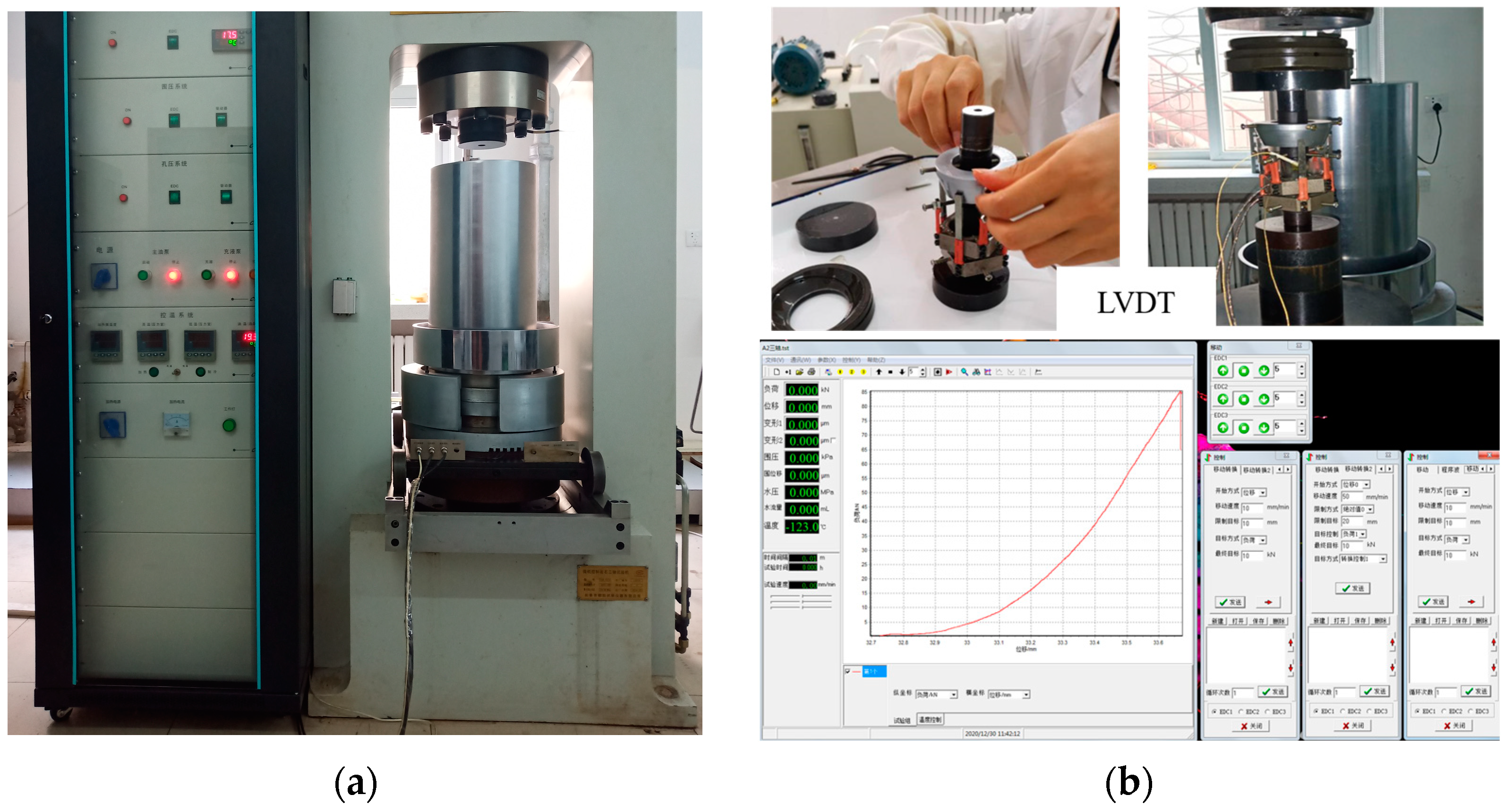
Figure 1. Rock mechanics experiment: (a) controlled rock triaxial testing machine by microcomputer; (b) software measurement and control system.
Energies 15 05620 g001
Figure 2. Calibration of the contact model to the laboratory specimen under UCS test: (a) numerical simulation of UCS test; (b) comparison of experimental results with numerical simulation results.
Energies 15 05620 g002
Figure 3. Calibration of the contact model to the laboratory specimen under Brazil test: (a) numerical simulation of tensile test; (b) comparison of experimental results with numerical simulation results.
Energies 15 05620 g003
Figure 4. Flow model in a bonded assembly of particles.
Energies 15 05620 g004
Figure 5. PFC2D model prior to injection.
Energies 15 05620 g005
Figure 6. Fracture network morphology under different time-steps and different horizontal in-situ stress difference coefficients: (a) fracture network morphology at different time-steps when horizontal in-situ stress difference coefficient Kh = 0.1; (b) fracture network morphology under different horizontal in-situ stress difference coefficients.
Energies 15 05620 g006aEnergies 15 05620 g006b
Figure 7. Quantitative evaluation method of fracture network complexity based on fractal dimension.
Energies 15 05620 g007
Figure 8. Evolution curve of fluid pressure–time–step at injection point.
Energies 15 05620 g008
Table 1. Test results of rock mechanical parameters.
Brazilian Splitting Test Results
NumberDepth
/m
Diameter
/mm
Height
/mm
Failure Pressure
/kN
Tensile Strength
/MPa
Average Tensile Strength
/MPa
E1340824.3223.9917.0318.58316.76
E2340824.4424.0114.68415.931
E3340824.324.0314.4515.754
E4340824.5124.218.0768.665-
Uniaxial/Triaxial Test Results
NumberDepth
/m
Confining Pressure
/MPa
Diameter
/mm
Height
/mm
E
/GPa
υσc
/MPa
Cohesion
/MPa
Internal Friction Angle
E13408024.3050.9233.550.051197.0843.0542.8
E23408524.2551.7034.630.088233.85
E334081024.3250.7434.800.052258.13
E434082024.4950.9735.810.098301.88
Table 2. Calibrated microscopic properties of the sandstone model.
ParametersRemarks and ReferencesValue (Unit)
Particle density (kg/m3)ρ2650
Lower bound of particle radius (mm)r2
Ratio of particle radiusRmax/Rmin1.66
Young’s modulus of the particle (GPa)E16
Ratio of normal to shear stiffness of the particlekn/ks3
Friction coefficient of particleμ0.577
Young’s modulus of the parallel bond (GPa)Epb16
Tensile strength of the parallel particle (MPa)σt15
Shear strength of the parallel particle (MPa)σs18
Cohesion (MPa)c35
Normal stiffness of SJM (GPa) k s s j m [36]1300
Shear stiffness of SJM (GPa) k s s j m [36]500
Tensile strength of SJM (MPa) σ t s j m [36]3.2
Friction angle of SJM (°)φ [27,36]30
Cohesive of SJM (MPa) c [36]3.2
Table 3. In-situ stress difference coefficient and hydraulic fracturing simulation results.
Specimen NumberIn-Situ Stress Difference Coefficient
/%
Tension CrackShear CrackTotal CracksFracture Stress
/MPa
Fractal
Dimension
D
AmountProportion
/%
AmountProportion
/%
10215591.12118.9236643.061.5654
210182690.020210.0202843.061.5373
320207990.82119.2229043.731.5604
430283690.92849.13120441.6094
540209391.02069.0229944.191.5667
650235790.62449.4260145.721.5759
760178289.520911.5199144.751.5989
870135889.615811.4151644.911.5376
980201990.12219.9224045.11.5543
1090271590.22929.8300744.311.6117
11100193889.822011.2215844.71.3924
Publisher’s Note: MDPI stays neutral with regard to jurisdictional claims in published maps and institutional affiliations.