Article

Super-Twisting Algorithm-Based Virtual Synchronous Generator in Inverter Interfaced Distributed Generation (IIDG)

1
Department of Electrical Engineering, Jamia Millia Islamia, New Delhi 110025, India
2
Department of Electrical Engineering, JSS Academy of Technical Education, Noida 201301, India
3
Department of Electrical Engineering Technology, University of Johannesburg, Johannesburg 2006, South Africa
*
Author to whom correspondence should be addressed.
Energies 2022, 15(16), 5890; https://doi.org/10.3390/en15165890
Submission received: 10 May 2022 / Revised: 30 June 2022 / Accepted: 12 July 2022 / Published: 14 August 2022
(This article belongs to the Special Issue Challenges and Research Trends of Renewable Energy Power System)

Abstract

:
The significant proliferation of renewable resources, primarily inverter interfaced distributed generation (IIDG) in the utility grid, leads to a dearth of overall inertia. Subsequently, the system illustrates more frequency nadir and a steeper frequency response. This may degrade the dynamic frequency stability of the overall system. Further, virtual inertia has been synthetically developed in IIDG, which is known as a virtual synchronous generator (VSG). In this work, a novel STO-STC-based controller has been developed, which offers flexible inertia following system disturbance. The controller is based on the super-twisting algorithm (STA), which is a further advancement in the conventional sliding mode control (SMC), and has been incorporated in the control loop of the VSG. In this scheme, two steps have been implemented, where the first one is to categorize all states of the system using a super-twisting observer (STO) and further, it is required to converge essential states very quickly, exploiting a super-twisting controller (STC). Thus, the STO-STC controller reveals a finite-time convergence to the numerous frequency disturbances, based on various case studies. The performance of the controller has been examined in the MATLAB environment with time–domain results that corroborate the satisfactory performance of the STO-STC scheme and that illustrate eminence over the state of the art.

1. Introduction

The increasing penetration of renewable energy sources, mainly IIDG, has endangered frequency stability concerns in the low inertia system, due to the unavailability of the rotating mass [1]. Thus, inertia emulation is urgently required in IIDG to assist with frequency regulation [2]. Commonly, synchronous machine (SM) droop characteristics have been developed virtually in IIDG, which is popularly known as a virtual synchronous generator (VSG). Therefore, VSG-IIDG is essentially required in frequency regulation. A VSG control scheme has been presented in [3,4], in which the swing equation of an actual SM has been utilized. Moreover, in recent years, several VSG control schemes were presented, in which the active power extracted from IIDG has been exploited to regulate the frequency deviation, the rate of change of frequency (RoCoF), and the settling time. Nevertheless, IIDG has some active power constraints that mainly depend upon maximum power point tracking (MPPT). Further, various control schemes have been developed that are based on droop control [5,6], in which the droop characteristics are employed to regulate a fraction of the active power in accordance with the frequency deviation. In addition, the various parameters (inertia constant, damping constant, and droop slope) required to regulate the active power supplied through IIDG have been optimized through a number of presented schemes [7,8]. Nonetheless, for simplicity, there has been barely two parameters (inertia and damping) that have been incorporated in the basic design of VSG. In addition, there is an inherent trade-off between a selection of various parameters and the accomplishment of the required aspect viz. RoCoF, the settling time, the frequency regulation, and the minimization of the frequency nadir. Further, there will be no alternative approach to regulating all of the discussed aspects simultaneously, depending upon the selection of the parameters. Lastly, it is quite problematic to tune the various parameters of VSG to achieve all of the requirements at the same time, since a variation to any of them can negatively affect another performance.

1.1. Motivation of Work

In recent years, VSG control schemes have been extensively studied and investigated, especially for IIDG, considering both the grid-connected and islanded modes. VSG-IIDG has been designed to support the frequency dynamics, and to minimize the output power and frequency oscillations. Several control techniques have been developed to suppress the frequency and power oscillations [9]. The proper selection of the inertia and damping constants can effectively reduce both of these oscillations. Further, to have a proper acquaintance with VSG design, small-signal modeling has been discussed in several papers [8,10] that provide more precise parameters for the emulated inertia. Further, a VSG based on an adaptive linear quadratic regulator has been proposed in [11]. A VSG scheme discussed in the literature has considered only a few IIDGs in the proposed test system, which lacks authenticity; thus, reliability is still an open problem. Secondly, the effectiveness of previously presented schemes in both standalone and grid-connected modes still requires intense study. The grid-connected IIDG has been recognized to be more sensitive to voltage sag/swell and exposure to unbalanced conditions. The VSG design should be well-operated in both the modes, and lastly, the controller performance is required to be more robust, as per the variation of various parameters.

1.2. Literature Survey on Recent State of Art

A self-tuning algorithm (STALG) in VSG has been proposed in [2]. Further work in self-tuning was given in [12], which was developed based on a RoCoF, and it provides the optimal virtual inertia (VI) via the proper selection of the inertia and damping constants. Since IIDG is a non-linear system, owing to the power–voltage characteristics, many control schemes were therefore developed based on the linearized model with proportional-integral viz. PI controller for inertia emulation. Subsequently, linearized feedback non-linear control schemes have been discussed in the literature, which provide enhanced performance over linear control design. Nonetheless, the non-linear design performs well on optimal parameter selection and an accurate operating point, which is slightly difficult to design. Furthermore, an AI-based VSG has been presented in [13], and further, a neural-fuzzy VSG (N-F-VSG) was designed in [14], which is a more reliable structure for enhancing the frequency dynamics. Recently, a model predictive control (MPC) has been portrayed in the literature, which has been proven to be an excellent VSG design [15,16]. The fuzzy-based VSG (Fuzzy-VSG), which computes the correction factor required to alter the governor output during a sudden disturbance, was discussed in [17]. The improved MPC scheme has been suggested in [18], which was a superior design for emulating the virtual inertia.

1.3. Contribution

As per Table 1, several eminent controllers have been organized, where M. A. Torres [2] suggested a self-tuning virtual synchronous machine that tunes the inertia constant as per the severity of disturbance. Further, J. Alipoor demonstrated the concept of alternating the moment of inertia in [3]; however, it only tunes the constants (inertia and damping) with a slothful response. M. H. Ravanji et al. suggested a swing equation-based virtual inertia, in which the DFIG wind turbines participate in frequency regulation, although it addresses only frequency oscillations and RoCoF. In [13], a fuzzy-based controller has been suggested, but it exhibits a sluggish response after the disturbance. A. Karimi et al. in [17] presents a fuzzy-based controller and computes the correction term needed to adjust the governor output power during a disturbance; however, as in [13], the same controller suffers from a sluggish response. As per the power voltage characteristics, renewable generation is a non-linear system, and consequently, non-linear controllers have been introduced in the literature. In addition to this, artificial intelligence (AI)-based VSG is projected in [13]; however, non-linear controllers need accurate parameter identification for a superior performance; therefore, a model prediction controller [18] has been further explored to determine the optimal power requirement by RES during the disturbance. It determines the real power for IIDG in real-time, using a predictive framework. However, the performance evaluation of the suggested MPC suffers in the identification of the optimal real power set point. Primarily, the proposed work focuses on a comparison with the eminent state of the art, as discussed above, and reveals the performance of the proposed controller. Conventional constant parameter (CP-VSG) and zero VI have also been taken into consideration in numerous case studies. A time–domain analysis obtained on an IEEE 14 bus test system developed in MATLAB, and the simulation results, corroborate the superiority of a proposed STO-based STC over the current state of the art. Time–domain specifications such as settling time, DC voltage variation, and generator-1 settling time have been exploited for numerous popular schemes viz. fuzzy-based VSG, AI-based VSG, and MPC schemes subjected to three phase faults on bus-12. These comparisons have been compiled in later sections. Furthermore, the normalized power supplied during the disturbance has also been plotted for various schemes, as discussed above, and compared with this STO-STC scheme. The super-twisting observer can work in the presence of any kind of bounded disturbances and converge in finite time. Further, if one state of the system is known, then also it can track all the information of the system in finite time. Thus, it reduces the required number of sensors in the system.
The key outcomes of this work have been given below:
  • Super-twisting is a novel scheme to identify all the states in finite time t < T0 with the minimum number of required sensors.
  • The super-twisting controller converges very quickly and provides the accurate real power required for inertia emulation under finite disturbance d1.
  • This novel controller efficiently improves the frequency dynamics.
  • The suggested controller illustrates a superior performance over the recent popular controllers viz. model prediction, fuzzy, or self-tuning controllers.

2. Mathematical Modeling of Proposed VSG Dynamics

In this section, the VSG-IIDG dynamic equation has been developed in the d-q reference frame [19], which is based on two control loops corresponding to the active power and reactive power exchange.

2.1. Non-Linear Dynamics of VSG-IIDG

The 3-Φ active power is basically computed as [20,21], which is given below:
P e = v d i d + v q i q
whereas v d , v q , i d , i q are voltages and currents in inverter terminals on the d-q reference frame. The transformation from a-b-c to d-q requires the phase angle θ, which is computed from the second-order generalized integrator, SOGI PLL [22]. In a conventional synchronous machine (SM), a well-known inertia equation viz. swing equation of rotor dynamics has been given as follows.
J ω m ω m . = P m P e D ( ω 0 ω m )
where, ω0 is the nominal angular frequency of VSG-IIDG, ωm is the measured angular frequency obtained through SOGI-PLL, J is the moment of inertia, and D is the damping coefficient [23]. Further, a high value of D brings the measured frequency more quickly to the nominal value. Pm is the governor output power. Further, as with conventional SM, the governor model is included in this modeling, as given in Equation (3):
P m = P 0 + K g ( ω 0 ω )
where, P0 is the set active power and Kg is the governor droop coefficient. ω is the angular frequency generated by the swing equation. Furthermore, one more loop corresponds to the reactive power Qe for voltage droop control. The reactive power on the d-q coordinates are given as [20,21]:
Q e = v d i q v q i d
The output voltage of the VSG-IIDG is governed by the following dynamics:
V = ( K P + K I s ) ( Q * Q e )
Kp, KI are PI (proportional and integral gains). Q* is the reactive power reference.
In addition, the voltage droop generates reference Q*, which is given by:
Q * = Q 0 + K q ( V 0 V r )
where Kq is the droop coefficient and Q0 is the set reactive power. Further, V r is the rms value of the inverter side voltage (PCC), and V 0 is the reference voltage. Now, upon differentiating Equation (5), we get:
V . = K P Q * . + K I Q * K P Q e . K I Q e
Thus,
V . = K P Q * . + K I Q * K P Q e . K I Q e
Q * ˙ can be neglected with respect to the frequency dynamics; therefore:
V . = K P Q e . + K I ( Q * Q e )
Now, Equations (2) to (8) illustrate the non-linear behavior of VSG-IIDG. Therefore, a non-linear controller such as the sliding mode control (SMC) is required to handle these non-linearities, which enhances the performance of VSG-IIDG, as shown in Figure 1. In this paper, the super-twisting viz. ST algorithm has been developed and incorporated to improve the inertial response in both the grid-connected and autonomous modes. The designed ST algorithm produces a correction factor, as shown in Figure 1, which is the final modification in the governor output power or input power to the swing; Equation (2). The input variables to the ST algorithm are ω m , ω ˙ m .

2.2. VSG-IIDG Scheme

To design the super-twisting control (STC), we need the information for both ω m , ω ˙ m in finite time under the finite disturbance. The super-twisting observer (STO) has been required for this purpose. The initial knowledge regarding this control has been taken from [19] and [24].

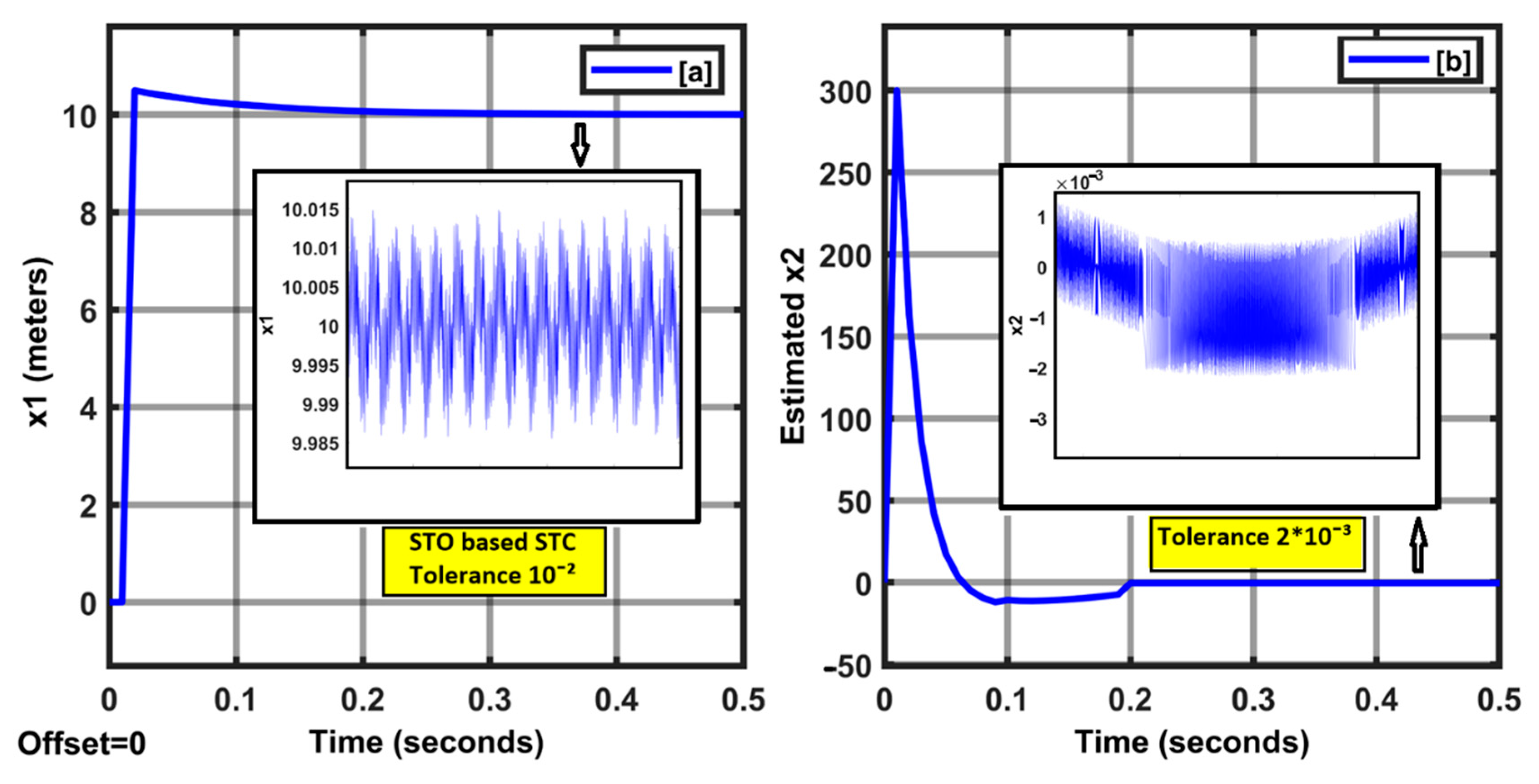
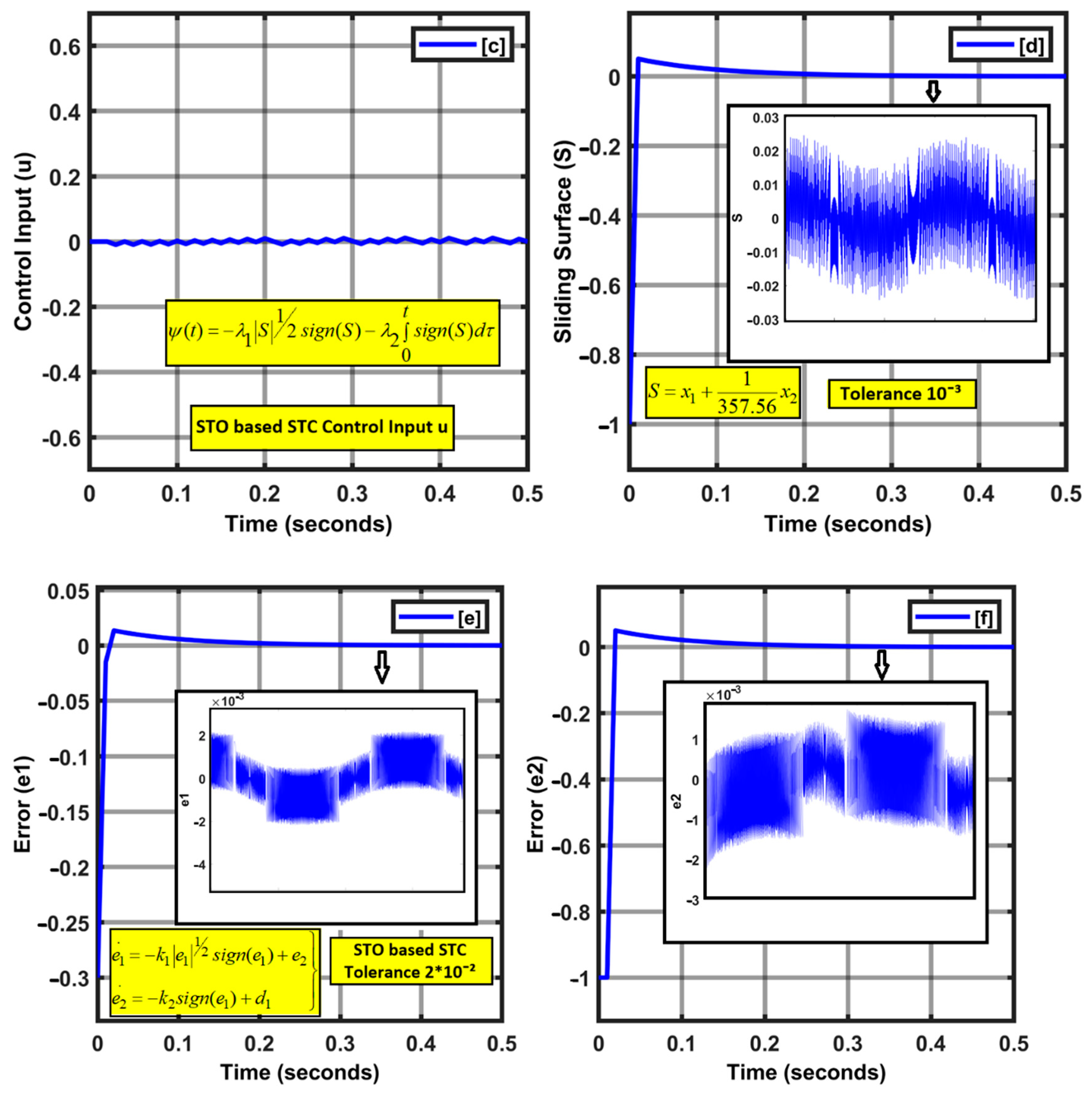
2.3. STC Based on STO

Consider the mathematical modeling of the dynamic system:
x 1 . = x 2 x 2 = u + d 1 . }
The output of the system is given as σ = x 1 , and d1 is a finite external disturbance. The design of STC is based on the other states of the system, rather than the output information. STO has been proven to be the best observer [25], which can compensate for time- varying (TV) disturbances within finite time t < T0. STO is based on a high-order SMC (HOSMC). The STO dynamics [26,27] for the estimation of the system states (a copy of the dynamic system) have been evaluated as:
x ^ 1 . = ξ 1 + x ^ 2 x ^ 2 . = ξ 2 + u }
In STO design, we neglected the unknown d1; further, ξ 1 , ξ 2 are correction terms. The error variables are defined as e 1 = x 1 x ^ 1 and e 2 = x 2 x ^ 2 .
Our objective is to estimate x 1 , x 2 in finite time, t < T0. Furthermore,
x = [ x 1 x 2 ] = [ ω m ω m . ]
Now, the derivative of the error, e 1 . = x 1 . x ^ 1 . = x 2 x ^ 2 ξ 1 = e 2 ξ 1
Similarly, e 2 . = x 2 . x ^ 2 . = u + d 1 u ξ 2 = d 1 ξ 2
Selecting ξ 1 , ξ 2 in such a way that e 1 , e 2 0 t T 0 ; thus, as per [25], the correction terms will be as given as ξ 1 = k 1 | e 1 | 1 2 s i g n ( e 1 ) and ξ 2 = k 2 s i g n ( e 1 ) . In these equations, e 2 is missing due to the lack of information regarding this error variable, and further, the correction factors are based on e 1 only. Now, STA based on e 1 , e 2 is given as follows:
e 1 . = k 1 | e 1 | 1 2 s i g n ( e 1 ) + e 2 e 2 . = k 2 s i g n ( e 1 ) + d 1 }
It has been assumed that the finite disturbance | d 1 | < δ 0 . Now, based on the literature available [19,25], if we choose k 1 = 1.5 δ 0 and k 2 = 1.1 δ 0 , which have assured convergence, e 1 , e 2 0 t T 0 , and finally:
x 1 = x ^ 1 x 2 = x ^ 2 } t T 0
Therefore, in a second-order system, using a higher-order sliding mode observer viz. STO, one can estimate numerous states of the system in finite. This observer exposes an acceptable performance in terms of finite time robust estimation. Now, the next section discusses the controller design.

2.4. ST Control Algorithm and Design

For the controller design, a relative degree of two is required. However, STC would be applicable for a relative degree of one only. Accordingly, the sliding manifold has been modified to obtain a required relative degree of one.
S = c x 1 + x 2 S . = c x 1 . + x 2 = c x 2 + u + d 1 }
Let the controller be given as u = c x 2 + ψ ( t ) as shown in Figure 2, where, according to the ST algorithm, ψ ( t ) is defined as:
ψ ( t ) = λ 1 | S | 1 2 s i g n ( S ) λ 2 0 t s i g n ( S ) d τ
where λ 1 = 1.5 δ 0 and λ 2 = 1.1 δ 0 . Further, Δ is defined on the finite disturbance as δ 0 | d 1 | . . After the control input, we get:
x 1 . = S c x 1 + e 2 S = c e 2 λ 1 | S | 1 2 s i g n ( S ) λ 2 0 t s i g n ( S ) d τ + k 2 s i g n ( e 1 ) }
Furthermore, the Lyapunov stability of the suggested STO-based STC has been dependent upon the error dynamics e 1 , e 2 . Since the correction factors are based on e 1 only, the Lyapunov function has been chosen for σ . For STC, the scaled function has been taken as σ . = k 1 | σ | 1 2 s i g n ( σ ) . Now, assuming the Lyapunov function as follows:
V = 1 2 σ 2 , σ
V is continuous and positively defined ( V > 0 ) . However, it is non-differentiable at V ( 0 ) = 0 . The error dynamics should be globally asymptotically stable, based on the selected ST gains.
Now,
V = σ σ . = k 1 | σ | 1 2 σ s i g n ( σ ) = k 1 | σ | 3 2 < 0
where σ s i g n ( σ ) = | σ | . Thus, it has been concluded that the error dynamics converge to zero in finite time t T 0 . To obtain the effectiveness of the STO-based STC controller, here, we tried to observe and explore the attributes of the suggested controller. Consider a very simple physical system that is a moving car system driven by some controlled input (u). The system state space can be written based on Newton’s law, and the displacement vector is given as x1 and the velocity vector x 1 . = x 2 . Further, at the equilibrium point, x 1 . = x 2 = 0 . This simple system has been examined with the proposed controller, where the disturbance is d 1 = 0.5 sin ω t with ω = 1 rad/s. The sliding surface has been chosen as S = x 1 + 1 357.56 x 2 . For simulation purposes, the controller gains have been given as follows.
-
STO gains: k 1 = 2.1 , k 2 = 2.2 ;
-
STC gains: λ 1 = 2.1 , λ 2 = 1.55 ;
-
Constant c = 1 , sampling time (MATLAB) = 1 ms.
The twisting observer and controller algorithm have been written in a MATLAB function, and the prime objective of the controller is to bring the vehicle to the desired position, starting from the zero position. The simulation results have been portrayed in Figure 3. As per the results obtained in Figure 3, the suggested controller works well with a good precision of 10 3 .
Furthermore, the same controller has been utilized for virtual inertia emulation on the IEEE 14 bus test system, with the output σ = Δ P , where Δ P is the additional power required for the virtual inertia emulation, as per the frequency deviation Δ ω m and the rate of change of frequency ω . m .
In this paper, a sudden load change has been taken as 2 pu. Therefore, δ 0 = 2 has been selected. The STO and STC gains have been estimated earlier in this section.

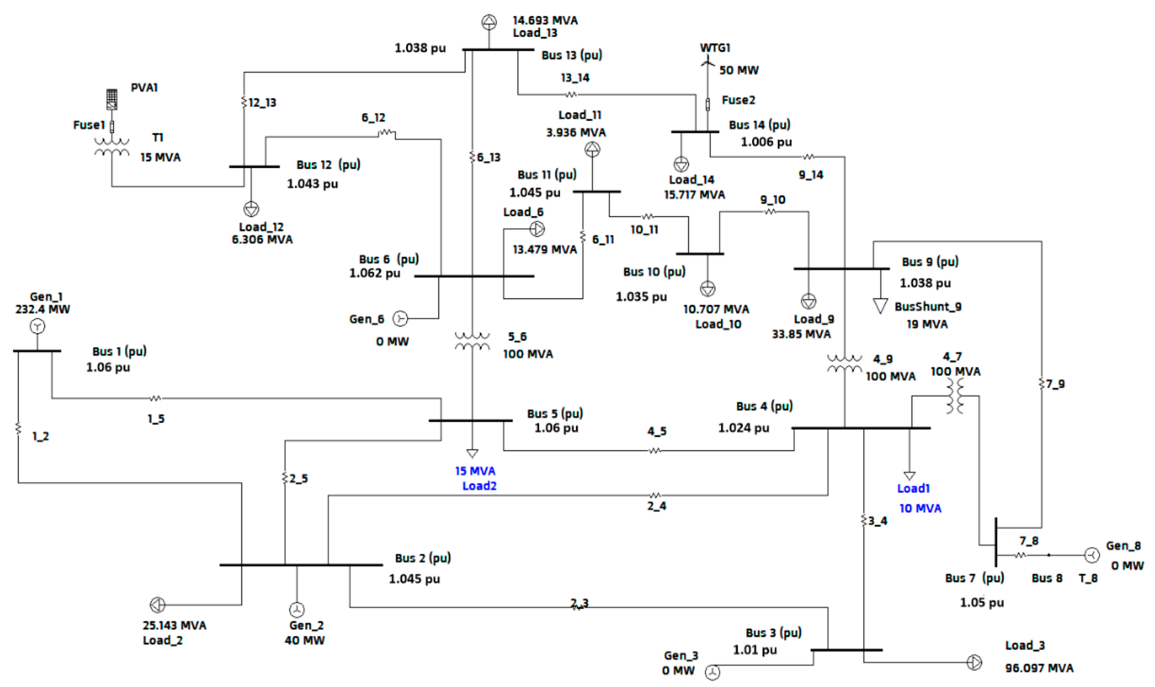
3. Test System Configuration and Setup

In this paper, the IEEE 14 bus system has been taken [23] as a test system. A 415 V photovoltaic system (IIDG) 0.5 MW has been incorporated at bus-12 through a 15 MVA transformer. Several synchronous generators are connected at various buses in isolation, or with some local demands.
Furthermore, various static and dynamic loads have been connected at different buses, as shown in Figure 4. At bus-9, the static Var compensator of 10 MVAR has been coupled. A 50 MW wind turbine generator (WTG) is connected at bus-14 to further supply a high demand at bus-13. In the test system, to obtain sufficient information on the voltage, power flow and angle, power flow analysis has been conducted, and the whole test system has been designed and developed on a MATLAB/Simulink MathWorks® platform. The open-circuit voltage of PV generation is 800 V, with a 600 A short circuit current. The fuses are usually incorporated to protect the PV generation, as shown in Figure 4, and are incorporated at various places. Now, for the inertia emulation, MPPT (maximum power point tracking) does not play a significant role, and it is omitted in the development of the MATLAB detailed model of a test system. The case study has been executed based on various factors, viz. sudden load change and intentional islanding. Further, during simulation, the temperature or irradiance variation have been omitted for simplicity, and a detailed model has been simulated based on ode 23tb, with a maximum step size of 1 ms. The voltage source inverter is an IGBT-based 2 level bridge inverter, which is efficiently regulated through pulse modulation. In this work, STO-based STC accurately measures Δ P based on the nominal frequency deviation and the rate of change of frequency ( ω m , ω . m ) , owing to the sudden bounded disturbance d 1 . The super-twisting observer and the controller algorithm have been already given in Equations (9)–(18), and consequently, the code is written in a MATLAB function. The efficacy of the proposed controller has been verified by numerous simulation results. The system parameters used in building the test system in MATLAB have been organized in Table 2.

4. Simulation Results and Performance Evaluation

As per the available literature [23,24,25], four main consecutive control steps have been utilized to restore the deviated frequency to the nominal value. 1. Inertial control 2. Primary control 3. Secondary control 4. Tertiary control. The fastest control is generally exhibited by SG, which instantaneously responds to supply–demand disturbance before the primary controller is activated. However, in recent years, SGs have been replaced by IIDGs to a large extent, and thus, the overall system damping and inertia are reduced significantly. Therefore, during load throw-off or numerous kinds of faults, primary control is not an effective solution to many problems, due to their sluggish response, which in the worst conditions causes blackouts or a complete failure of the system. The above discussion is shown in Figure 5.

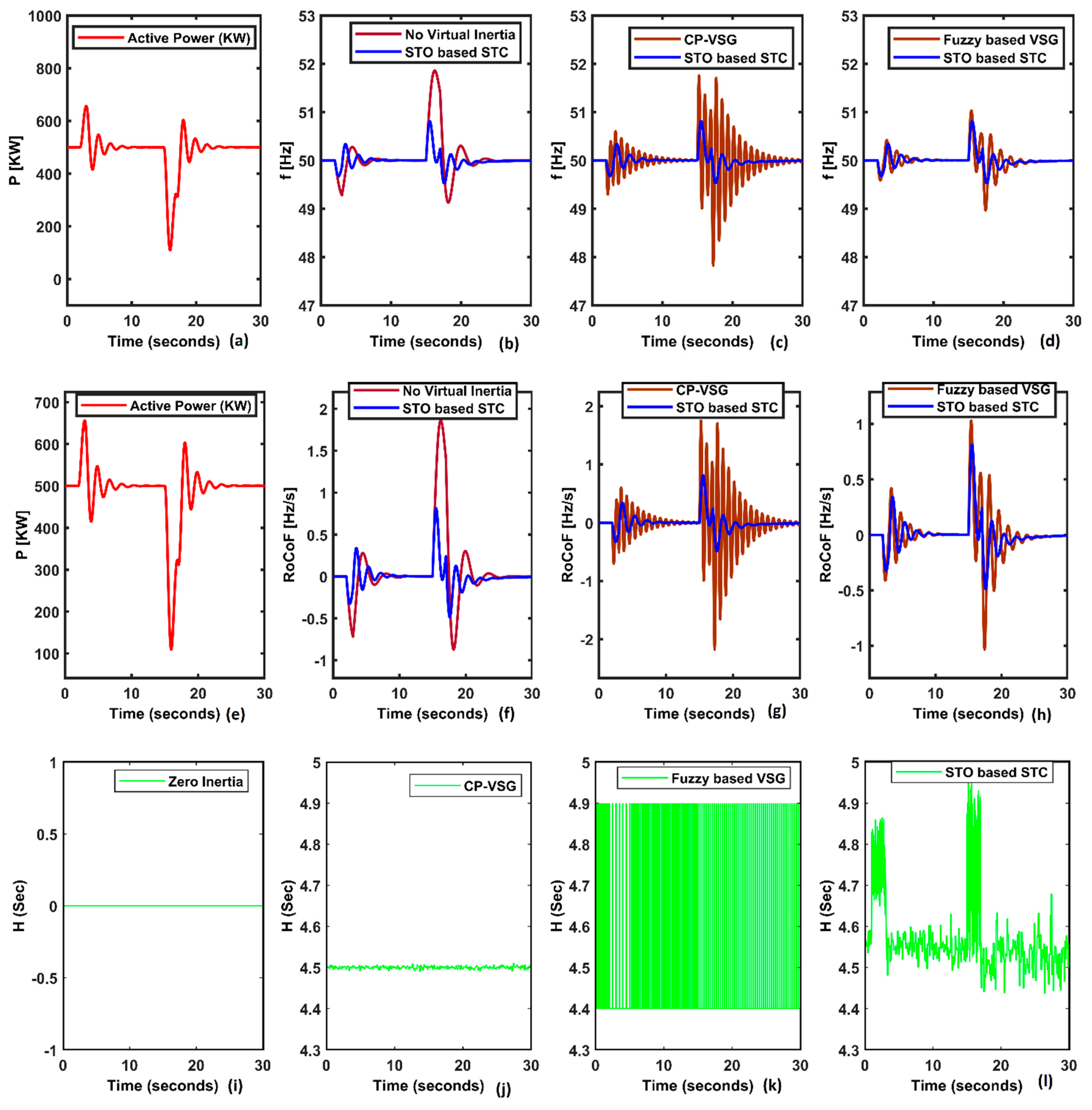
4.1. Sudden Load Variation in Grid-Connected VSG

In this scenario, the capability of the proposed STO-based STC has been investigated. The load changes at bus-12 from 500 kW (for simulation purposes, the load connected at bus-12 was taken to 500 kW instead of 6.306 MVA for simplicity in designing the MATLAB model) to 650 kW at t = 2 s, and subsequently, the frequency droop has been observed from the nominal value f n ; consequently, a load has been decreased by up to 100 kW at bus-12 at t = 15 s (a sudden load variation through variable AC resistors in MATLAB) and a frequency overshoot, along with RoCoF, has been investigated for the selected state of the arts.
The frequency dynamic for different control schemes has been portrayed in Figure 6. An IIDG with zero or negligible inertia suffers from an impulsive overshoot; nonetheless, the oscillating time has been drastically reduced, as compared to the constant parameter, viz. the CP-VSG scheme (a constant inertia fixed up to H = 4.5 s).
The obvious disadvantages of a fixed high-inertia system viz. CP-VSG are sustained periodic oscillations and a subsequently inferior dynamic performance. Furthermore, fuzzy-based VSG illustrates a superior inertia emulation during the disturbances, but the settling time of oscillation is high, as compared to the proposed STO-based STC. The proposed STO-based STC demonstrates RoCoF = −0.25 Hz/s at t = 2 s, and 0.75 Hz/s at t = 15 s, with a 49.9 Hz frequency nadir and a 50.5 Hz frequency overshoot. The investigated results recommend a superior dynamic performance of STO-based STC over numerous control schemes, as shown in Figure 6. The inertia emulation for various schemes has been examined, based on the swing equation [23], and is given as:
J = Δ P m Δ P e D ( ω m ω 0 ) ω m .
Now, the inertia J, and consequently, the inertia constant H ( s ) adaptively increased during the disturbances. STO-based STC efficiently emulates and regulates the inertia during disturbance, which is constant in the CP-VSM scheme. An encapsulation of the time–domain performance evaluation of popular controllers and STO-based STC on sudden load variation has been compiled in Table 3.

4.2. Inertia Response on AC Fault

A 3 Φ fault has been simulated and created at 1 s, and subsequently cleared at 1.5 s at bus-13. Further, the bus-12 voltage falls as per fault impedance, which has been portrayed in Figure 7a. Subsequently, the bus-12 frequency has been estimated after the occurrence of the 3 Φ fault, and the frequency plots for zero inertia, CP-VSG, and STO-STC have been shown in Figure 7b. The frequency response illustrated the superior damping capability of STO-STC, with a settling time of below 5 s after fault clearance. No VI exhibited an impulsive frequency rise, due to zero inertia emulation, and consequently, no variation in the DC-link voltage, as shown in Figure 7c. Furthermore, to observe the off-shore power fluctuation owing to fault occurrence at the same location, the bus-13 and SG-1 (bus-1) power oscillations have been examined, as shown in Figure 7d. This characterizes superior damping for the STO-STC-based IIDG at bus-12. Other schemes have also been compared and compiled in Table 4 and Table 5, respectively.

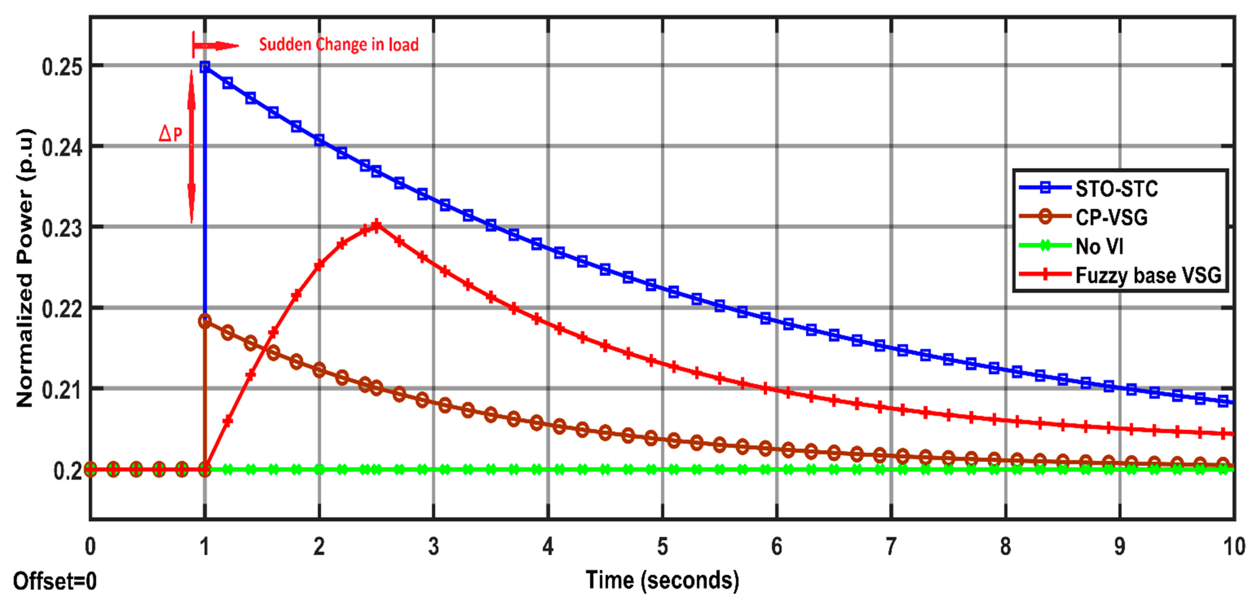
4.3. Normalized Active Power Response under Sudden Load Variation

Figure 8 exhibits normalized power extracted from IIDG on a sudden load change (ΔPL = 50 kW) on bus-13, next to bus-12. Numerous controllers have been taken to examine the power response at bus-12 required to mitigate the frequency variation and the frequency nadir.
It has been found that the virtual inertia response is impulsive and instantly injects active power to improve the dynamic frequency stability. Initially, IIDG was operating at 0.2 pu. Further, the injected active power dies out soon as the frequency normalizes to nominal values. Primarily, IIDG at bus-12 was delivering 0.2 normalized power, and at t = 2 s, sudden load changes to 50 kW and power responses have been captured in MATLAB, as shown in Figure 8. Further, in Figure 8 is a performance evaluation and comparison of various schemes on injected normalized power during a sudden load change (pu): Initially IIDG was operating at 0.2 pu.
STO-based STC estimates an accurate ΔP which is required based on the nominal frequency deviation and RoCoF ( ω m , ω . m ) owing to the sudden load change ΔPL, which is the bounded disturbance d 1 . Further, unlike fuzzy-based VSG, STO-STC exhibits an instantaneous power response and sustains supplementary injected power until the deviated frequency has not reached the nominal frequency. The time–domain simulation results illustrate the superior performance of the STO-STC scheme over recent popular controllers viz. model prediction, fuzzy-based VSG, CP-VSG, or self-tuning controllers. It is noteworthy that the emulated inertia by the STO-STC scheme increased adaptively during the disturbance, as shown in Figure 6l. Furthermore, optimal real power ΔP has been evaluated and injected during a sudden load change, as discussed in Figure 8. The proposed STO-STC scheme observes the various states using STO, and regulates the real power flow using STC during the disturbance. This will further enhance the overall dynamic frequency stability of the system.

5. Conclusions

In this work, a novel STO-tuned STC scheme has been efficiently explored and verified using time–domain simulation results. Firstly, the inertial response has been examined in grid-connected IIDG. The virtual inertia emulation has been proven to be the most promising scheme to enhance the dynamic frequency responses of low-inertia systems. Based on the mathematical modeling of VSG, it exhibits a non-linear behavior of VSG. Therefore, a non-linear controller such as sliding mode control (SMC) is required to handle these non-linearities, which enhances the performance of VSG-IIDG. Further, STO is based on high-order SMC (HOSMC). For STC design, STO evaluates numerous system states in finite time t < T0. The proposed STO-STC scheme evaluates the exact corrective active power ΔP, based on the optimal selection of system inertia, which reduces the frequency pulsations. The STO-STC scheme exhibits superior damping in a multi-machine system as compared to the popular schemes viz. the self-tuning STALG scheme, CP-VSG, fuzzy-based VSG, and the MPC scheme. This is accomplished by the optimal selection of inertia and corrective power ΔP, which regulate both the frequency and power variations. This scheme also works well in fault occurrence, which has been revealed through numerous case studies.

Author Contributions

Investigation, S.K.S. (Sudhir Kumar Singh); Methodology, R.S.; Resources, H.A.; Supervision, S.K.S. (Sanjeev Kumar Sharma); Writing—review & editing, G.S. and P.N.B. All of the authors contributed to designing and developing the mathematical model of IIDG, and the collection of numerous information. All authors have read and agreed to the published version of the manuscript.

Funding

This research received no external funding.

Institutional Review Board Statement

Not applicable.

Informed Consent Statement

Not applicable.

Data Availability Statement

Not applicable.

Conflicts of Interest

The authors declare no conflict of interest.

References

  1. Majumder, R. Some aspects of stability in microgrids. IEEE Trans. Power Syst. 2013, 28, 3243–3252. [Google Scholar] [CrossRef]
  2. Torres, L.M.A.; Lopes, L.A.C.; Morán, T.L.A.; Espinoza, C.J.R. Self-tuning virtual synchronous machine: A control strategy for energy storage systems to support dynamic frequency control. IEEE Trans. Energy Convers. 2014, 29, 833–840. [Google Scholar] [CrossRef]
  3. Alipoor, J.; Miura, Y.; Ise, T. Power system stabilization using a virtual synchronous generator with alternating moments of inertia. IEEE J. Emerg. Sel. Top. Power Electron. 2015, 3, 451–458. [Google Scholar] [CrossRef]
  4. Ravanji, M.H.; Parniani, M. Modified virtual inertial controller for prudential participation of DFIG-based wind turbines in power system frequency regulation. IET Renew. Power Gener. 2017, 13, 155–164. [Google Scholar] [CrossRef]
  5. Van de Vyver, J.; De Kooning, J.D.; Meersman, B.; Vandevelde, L.; Vandoorn, T.L. Droop control as an alternative inertial response strategy for the synthetic inertia on wind turbines. IEEE Trans. Power Syst. 2015, 31, 1129–1138. [Google Scholar] [CrossRef]
  6. Ofir, R.; Markovic, U.; Aristidou, P.; Hug, G. Droop vs. virtual inertia: Comparison from the perspective of converter operation mode. In Proceedings of the IEEE International Energy Conference (ENERGYCON), Limassol, Cyprus, 3–7 June 2018; IEEE: Piscataway, NJ, USA, 2018. [Google Scholar]
  7. Borsche, T.; Dorfler, F. On placement of synthetic inertia with explicit time-domain constraints. arXiv 2017, arXiv:1705.03244. [Google Scholar]
  8. Wang, F.; Zhang, L.; Feng, X.; Guo, H. An adaptive control strategy for virtual synchronous generator. IEEE Trans. Ind. Appl. 2018, 54, 5124–5133. [Google Scholar] [CrossRef]
  9. Khajehoddin, S.A.; Karimi-Ghartemani, M.; Ebrahimi, M. Grid-supporting inverters with improved dynamics. IEEE Trans. Ind. Electron. 2019, 66, 3655–3667. [Google Scholar] [CrossRef]
  10. Wu, H.; Ruan, X.; Yang, D.; Chen, X.; Zhao, W.; Lv, Z.; Zhong, Q.-C. Small-signal modeling and parameters design for virtual synchronous generators. IEEE Trans. Ind. Electron. 2016, 63, 4292–4303. [Google Scholar] [CrossRef]
  11. Markovic, U.; Chu, Z.; Aristidou, P.; Hug-Glanzmann, G. Lqr-based adaptive virtual synchronous machine for power systems with high inverter penetration. IEEE Trans. Sustain. Energy 2018, 10, 1501–1512. [Google Scholar] [CrossRef]
  12. Singh, S.K.; Singh, R.; Diwania, S.; Singhal, A.; Saway, S. Impact of Inverter Interfaced DG Control Schemes on Distributed Network Protection Recent Advances in Power Electronics and Drives. In Lecture Notes in Electrical Engineering; Springer: Singapore, 2021; Volume 707. [Google Scholar]
  13. Andalib-Bin-Karim, C.; Liang, X.; Zhang, H. Fuzzy-secondary controller-based virtual synchronous generator control scheme for interfacing inverters of renewable distributed generation in microgrids. IEEE Trans. Ind. Appl. 2018, 54, 1047–1061. [Google Scholar] [CrossRef]
  14. Lakshmi, V.S.; Purushotham, P. ANFIS controller with virtual synchronous generator control for parallel inverters in microgrids. Int. J. Innov. Technol. 2017, 5, 2155–2161. [Google Scholar]
  15. Wang, S.; Dehghanian, P.; Alhazmi, M.; Nazemi, M. Advanced control solutions for enhanced resilience of modern power-electronic-interfaced distribution systems. J. Mod. Power Syst. Clean Energy 2019, 7, 716–730. [Google Scholar] [CrossRef]
  16. Ademola-Idowu, A.; Zhang, B. Frequency Stability Using MPC-Based Inverter Power Control in Low-Inertia Power Systems. IEEE Trans. Power Syst. 2021, 36, 1628–1637. [Google Scholar] [CrossRef]
  17. Karimi, A.; Khayat, Y.; Naderi, M.; Dragičević, T.; Mirzaei, R.; Blaabjerg, F. Inertia Response Improvement in AC Microgrids: A Fuzzy-Based Virtual Synchronous Generator Control. IEEE Trans. Power Electron. 2020, 35, 4321–4331. [Google Scholar] [CrossRef]
  18. Yap, K.Y.; Sarimuthu, C.R.; Lim, J.M.-Y. Virtual inertia-based inverters for mitigating frequency instability in grid-connected renewable energy system: A review. Appl. Sci. 2019, 9, 5300. [Google Scholar] [CrossRef]
  19. Rosales, A.; Yu, Z.; Ponce, P.; Molina, A.; Ayyanar, R. VSG scheme under unbalanced conditions controlled by SMC. IET Renew. Power Gener. 2019, 13, 3043–3049. [Google Scholar] [CrossRef]
  20. Akagi, H.; Ogasawara, S.; Kim, H. The theory of instantaneous power in three-phase four-wire systems: A comprehensive approach. In Proceedings of the Conference Record of the 1999 IEEE Industry Applications Conference 34th IAS Annual Meeting (Cat. No. 99CH36370), Phoenix, AZ, USA, 3–7 October 1999; Volume 1, pp. 431–439. [Google Scholar]
  21. Schiffer, J.; Zonetti, D.; Ortega, R.; Stanković, A.M.; Sezi, T.; Raisch, J. A survey on modeling of microgrids: From fundamental physics to phasors and voltage sources. Automatica 2016, 74, 135–150. [Google Scholar] [CrossRef]
  22. Vekić, M.; Rapaić, M.R.; Šekara, T.B.; Grabić, S.; Adžić, E. Multi–Resonant observer PLL with real-time estimation of grid unbalances. Int. J. Electr. Power Energy Syst. 2019, 108, 52–60. [Google Scholar] [CrossRef]
  23. Singh, S.K.; Singh, R.; Ashfaq, H.; Kumar, R. Virtual Inertia Emulation of Inverter Interfaced Distributed Generation (IIDG) for Dynamic Frequency Stability & Damping Enhancement Through BFOA Tuned Optimal Controller. Arab. J. Sci. Eng. 2021, 47, 3293–3310. [Google Scholar]
  24. Zheng, X.; Wang, C.; Pang, S. Injecting positive-sequence current virtual synchronous generator control under unbalanced grid. IET Renew. Power Gener. 2019, 13, 165–170. [Google Scholar] [CrossRef]
  25. Kumari, K.; Chalanga, A.; Bandyopadhyay, B. Implementation of Super-Twisting Control on Higher Order Perturbed Integrator System using Higher Order Sliding Mode Observer. IFAC-PapersOnLine 2016, 49, 873–878. [Google Scholar] [CrossRef]
  26. Southall, B.; Bernard, F.B.; John, A.M. Controllability and Observability: Tools for Kalman Filter Design. In Proceedings of the British Machine Vision Conference, Southampton, UK; 1998. [Google Scholar]
  27. Xue, Y.; Pequito, S.; Coelho, J.R.; Bogdan, P.; Pappas, G.J. Minimum number of sensors to ensure observability of physiological systems: A case study. In Proceedings of the 2016 54th Annual Allerton Conference on Communication, Control, and Computing (Allerton), Monticello, IL, USA, 27–30 September 2016; pp. 1181–1188. [Google Scholar] [CrossRef]
Figure 1. Super-twisting algorithm-based VSG-IIDG.
Energies 15 05890 g001
Figure 2. Sliding mode observer-based sliding mode controller.
Energies 15 05890 g002
Figure 3. (a) Position vector x1 evolution, (b) estimated state vector x2 evolution, (c) control input (u) evolution, (d) sliding surface (S) evolution, (e) observer error (e1) of state x1, (f) observer error (e2) of state x2.
Energies 15 05890 g003aEnergies 15 05890 g003b
Figure 4. IEEE 14 bus test system (bus voltages in pu after power flow analysis).
Energies 15 05890 g004
Figure 5. Frequency dynamics over time with various control steps.
Energies 15 05890 g005
Figure 6. Grid-connected mode. (a) Active power variation, (bd) dynamic frequency response of various control schemes, (eh) rate of frequency variation for various control schemes, (il) inertia emulation.
Energies 15 05890 g006
Figure 7. (a) Bus-12 voltage sag during fault (pu), (b) bus-12 frequency overshoot (Hz), (c) DC-link variation on fault (V), (d) off-shore SG power fluctuation (pu): comparison for various schemes.
Energies 15 05890 g007
Figure 8. Performance evaluation and comparison of various schemes on injected normalized power during a sudden load change (pu).
Energies 15 05890 g008
Table 1. Comparison of current work eminence and state of the art.
Existing State of the ArtController DescriptionAttributes
M. A. Torres et al., 2014 [2]Self-tuning virtual synchronous machineEnergy storage system for inertia emulation
J. Alipoor et al., 2015 [3]Alternating inertia-based virtual SGTunes inertia and damping constants
M. H. Ravanji et al., 2017 [4]Swing equation-based virtual inertiaDFIG-based wind turbines
C. A. B Karim et al., 2018 [13]VSG based on fuzzy controllerDistributed generation in microgrid
S. Wang et al., 2019 [15]Advanced control solutionsEnhanced resilience in distribution system
A. Karimi et al., 2020 [17]Fuzzy-based VSMRegulated governor output and correction term
A. A-Idowu et al., 2021 [16]MPC (model predictive control)Optimal power set points
Proposed workSTC based on STOEnhance frequency dynamics in multi-machine system
Table 2. Test system parameters.
System ParametersValues
DC-link voltage (VDC)800 V
Nominal frequency (fn)50 Hz
Output inverter voltage450 V
Inertia constant (H)4, 7, 10 s
Maximum irradiance1000 W/m2
Temperature (T)38 °C
Parallel strings76
Series modules23
Open circuit voltage (Voc)36.3 V/Module
Short circuit current (Isc)7.84 A/Module
Nominal voltage835 V(DC)
Nominal current598 A(DC)
Max power/module213.15 W
Speed regulation of governor (R)0.05 pu
Inertia of synchronous generator (H)4 s
Table 3. Performance evaluation and comparison on sudden load change.
Control SchemeNo VICP-VSGSTO-Based STC
Attributes
Frequency nadir [Hz] 49.2 (Violates IEEE 1574)49.449.8
Frequency overshoot [Hz]52 (Violates IEEE 1574)51.950.9
RoCoF [Hz/s]−0.8−0.7−0.3
Steady state error (%)1.450.70.13
Settling time [ts/s]5103
Inertia H [s]04.5Adaptive (4.4–4.9)
Control SchemeFuzzy-Based VSGSTALGMPC Scheme
Attributes
Frequency nadir [Hz]49.849.749.6
RoCoF [Hz/s]−0.4−0.5−0.3
Settling time [ts]43.74.2
Table 4. Time–domain specifications on a three phase fault (bus-12).
AttributeFuzzy Based VSGSTO-STCMPC Scheme
Settling time (s)66.3 oscillatory responses5.8
DC link variation (V)5713
Bus-1, Gen.1 settling time (s)1298
Table 5. Time–domain specifications with off-shore performance assessment.
AttributeNo VICP-VSGAI Based VSG
Settling time (s)Unspecified20 oscillatory responses6.5
DC link variation (V)No variation59
Bus-1, Gen.1 settling time (s)20148
Publisher’s Note: MDPI stays neutral with regard to jurisdictional claims in published maps and institutional affiliations.

