Article

Predicting the Optimal Performance of a Concentrated Solar Segmented Variable Leg Thermoelectric Generator Using Neural Networks

1
Department of Nuclear Science and Engineering, Massachusetts Institute of Technology, Cambridge, MA 02139, USA
2
Department of Mechanical Engineering, College of Engineering, Jazan University, Jazan 45142, Saudi Arabia
3
Mechanical Engineering Department, Engineering College, University of Ha’il, Ha’il 81451, Saudi Arabia
4
Department of Mechanical and Industrial Engineering, Abu Dhabi University, Abu Dhabi 59911, United Arab Emirates
*
Authors to whom correspondence should be addressed.
Energies 2022, 15(16), 6024; https://doi.org/10.3390/en15166024
Submission received: 16 June 2022 / Revised: 15 August 2022 / Accepted: 18 August 2022 / Published: 19 August 2022

Abstract

:
The production of high-performing thermoelectrics is limited by the high computational energy and time required by the current finite element method solvers that are used to analyze these devices. This paper introduces a new concentrating solar thermoelectric generator made of segmented materials that have non-uniform leg geometry to provide high efficiency. After this, the optimum performance of the device is obtained using the finite element method conducted using ANSYS software. Finally, to solve the high energy and time requirements of the conventional finite element method, the data generated by finite elements are used to train a regressive artificial neural network with 10 neurons in the hidden layer. Results are that the power and efficiency obtained from the optimized device design are 3× and 2× higher than the original unoptimized device design. Furthermore, the developed neural network has a high accuracy of 99.95% in learning the finite element data. Finally, the neural network predicts the modified device performance about 800× faster than the conventional finite element method. Overall, the paper provides insights into how thermoelectric manufacturing companies can harness the power of artificial intelligence to design very high-performing devices while saving time and cost.

1. Introduction

The exponential increase in greenhouse gas emissions has led to the search for more efficient green energy systems [1]. Among several green energy systems, solar-energy-powered devices stand out due to the global availability of solar energy in every location on the Earth [2]. On the other hand, about one-third of the energy generated by internal combustion engines is exhausted to the environment as waste heat which significantly increases the rising level of global warming [3]. This is why there have been recent, accelerated research thrusts in developing efficient waste heat conversion systems, such as thermoelectric generators (TEGs), that directly convert heat to electricity via thermoelectric effects [4]. Due to the versatility of TEGs, they have found various applications in concentrating solar power [5], waste heat scavenging in military vehicles [6], the Mars Curiosity rover [7], and even body waste heat utilization [8]. Despite these desirous advantages, their widescale reliance is hindered by their very low efficiencies [9]. Hence, efforts are being made to increase the device efficiency from device design [10,11] and material property tweaking [12] perspectives. More information on how thermoelectric device performance can be enhanced can be obtained from refs. [13,14,15].
Previous efforts have tried to enhance the thermoelectric efficiency by altering the device geometry design [16,17]. The conventional geometry design of a TEG is the rectangular leg geometry, which was found to be less efficient in handling thermal energy than the variable area leg geometries [18]. The variable area leg geometries that have been studied include the trapezoidal/prism [19], X [20], cylindrical [21], exponential [22], and hollow [23] geometries. Variable area leg geometries provide higher efficiencies than the conventional rectangular leg geometry due to their ability to absorb a higher amount of heat at the TEG hot junction while rejecting more heat at the TEG cold junction [24]. This is majorly due to the area difference between the top and bottom surfaces of the leg geometry compared to the same area distribution in the conventional rectangular area leg geometry. In the case of the cylindrical leg geometry, the top and bottom areas do not differ, but the smooth, circular edges provide lower thermal stresses compared to the rectangular leg geometry [25]. This is why the circular leg TEG provides a higher operational lifetime than the conventional rectangular leg TEG. Figure 1 shows the various leg geometries that have been previously explored. Hong et al. [11] utilized material segmentation and finite-element-aided geometry optimization techniques to design a 16% efficient thermoelectric device with a high figure of merit of 2.2.
In addition to device design alteration, other researchers have channeled their efforts into modifying the material properties of thermoelectric materials [26,27]. In this regard, material segmentation has been explored rigorously [28,29]. Segmentation relates to stacking up more than one material in a single thermoelectric leg. The materials that make up a segmented thermoelectric pin are high-temperature and low-temperature materials. The high-temperature material is placed closer to the device hot junction, while the cold-temperature material is located near the device cold junction. The segmented device design enables the TEG module to operate optimally under high-temperature conditions [29]. If the conventional unsegmented TEG is operated in extremely high-temperature conditions, the power output and efficiency of the device begins to decrease beyond an optimal working temperature [30]. However, the high-temperature and low-temperature materials in the segmented TEG design enable the device to generate higher power and efficiencies even under high concentrated heat fluxes [31].
Very few researchers have tried to combine material segmentation and device geometry design alteration to form a hybrid device that is able to provide a higher performance. Liu et al. [32] designed a new TEG that combines segmentation and asymmetrical leg geometry using a 3-dimensional model developed in COMSOL multiphysics software. They found the optimal geometry dimensions of the device, and they concluded that the original device design was improved by 14.9% and 16.6% when the optimized device configuration was used. The analysis of a segmented annular TEG device was already carried out by Fan and Gao [33], who reported that the output power of the segmented device was 18.3% higher than that of the single skutterudite design. Ruiz-Ortega et al. [34] conducted a 1-dimensional, FEM-assisted analysis of a single p-type segmented variable area leg thermoelectric cooler. They disclosed that the cooling capacity of the thermoelectric cooler was enhanced by 4.75% when trapezoidal legs were used in place of conventional rectangular legs. Nevertheless, the optimum geometry dimensions that are needed to harvest maximum efficiencies and power outputs from the modified device design were not provided. This work seeks to fill in this gap.
There have been some concerns in the TEG community regarding the extremely long time and high computational energy required by FEM-based solvers, such as ANSYS, ABAQUS, and COMSOL multiphysics software, when optimizing the performance of thermoelectric devices [35]. This is because of the complex nature of the governing heat and current density equations when solved in three dimensions. This problem becomes more obvious when the temperature dependency of the thermoelectric materials that comprise the TEG is considered in the virtual model [36]. This is why several theoretical studies on TEG optimization completely neglected the effect of temperature dependency in modelling the thermoelectric device [37,38], thereby, resulting in an overestimation of the device performance [39]. It becomes even more complicated when segmented thermoelectric materials are considered because these equations have to be solved simultaneously and repetitively for each node and grid point. This is a time-consuming process that requires very high computational energy and, ultimately, cost. This has hindered the ease with which useful optimization insights can be drawn from numerical studies which can be used in manufacturing high-performing thermoelectric devices. However, data-driven models, such as the artificial neural network (ANN), can be used to learn the trends in the data generated by these multiphysics solvers. After learning the data, the ANN can be used to easily predict the performance of the TEG in a matter of seconds [40]. This is because, unlike the multiphysics solvers, the ANN does not need to solve any time-consuming, 3-dimensional energy and current conservation equations [41]. It simply learns how the data behave by transferring information from one neuron to the other (just like the human brain) and then is able to make accurate predictions. This work seeks to overcome the time- and energy-consuming demands of the conventional multiphysics model by introducing ANNs as a suitable substitute for predicting the device performance under different operating conditions. The temperature dependency of all thermoelectric materials in the segmented pins is also considered to ensure accurate results are obtained.
The literature survey shows that much work has been carried out regarding improving the TEG performance using material segmentation and leg geometry alteration. This research work aims to add to the existing body of knowledge in the following ways:
  • Very few works have combined material segmentation and device geometry modification to form a new device configuration with higher performance. Moreso, these works lack in-depth insights regarding the optimum geometry combinations that can produce maximum power outputs and efficiencies from the device. This study, for the first in time, conducts this optimization analysis, uncovering the best combination of heights and cross-sectional areas needed to manufacture a high-performing, modified device. After this study, the optimization insights drawn from this study will be sent to TEG manufacturing companies, such as Kryotherm, who specialize in producing state-of-the-art thermoelectric modules;
  • A means of overcoming the high computational energy and time requirements of traditional, FEM-based multiphysics solvers is introduced by using ANNs. These ANNs ease and speed up the rate at which useful information can be drawn from the performance of the device through data prediction based on successful training. It is expected that the ANNs can predict the device performance much faster than the conventional, time-consuming, FEM-based methods. So far, ANNs have not been used to predict the performance of either segmented or variable area leg thermoelectrics;
  • Therefore, the purpose of this research paper is to, first of all, develop a 3-dimensional digital twin model of a modified, segmented variable area leg TEG using ANSYS software. After this, a comprehensive geometry optimization of the different segments is carried out to find the optimum lengths and areas that maximize the new device power and efficiency while considering all temperature-dependent thermoelectric properties and effects. Finally, an ANN model is introduced as a substitute for the computational time- and energy-consuming, traditional, FEM-based multiphysics software. This provides an accurate, faster, and more efficient way of predicting the device performance under different working conditions. In the end, the optimization insights provided by this study will be very useful to TEG manufacturing companies, such as Kryotherm, that specialize in manufacturing next-generation thermoelectric devices.

2. Materials and Methods

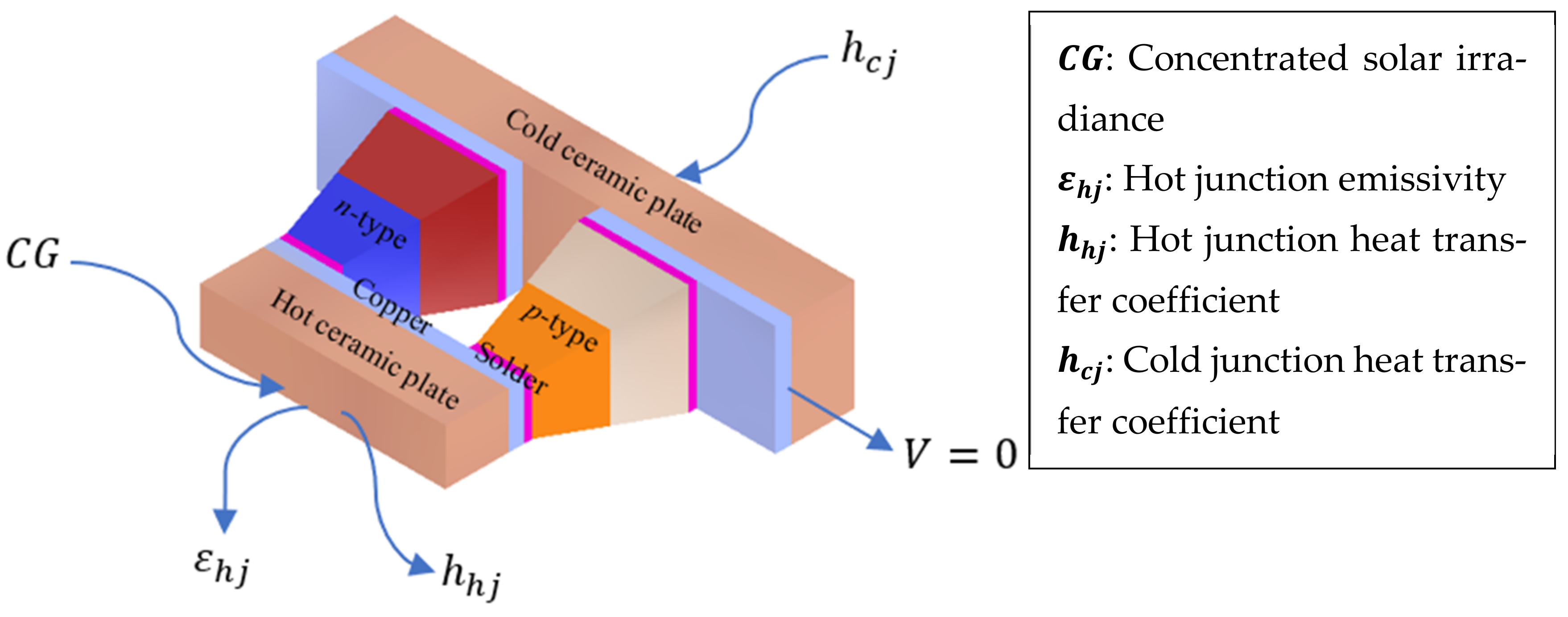
2.1. System Description

The first step was to develop the virtual computer-aided design (CAD) model that was used for the simulation. The CAD model was developed using Autodesk Inventor (San Rafael, CA, USA) 2023 software, and the geometry dimensions of the thermoelectric legs were fully parametrized to enable compatibility with ANSYS (Canonsburg, PA, USA) 2020 R2 finite element method (FEM) solver software. The virtual CAD model of the device design, alongside the boundary conditions in annotated form, are clearly depicted in Figure 2. The predefined CAD was defined in the FEM solver by specifying some important boundary conditions that are needed to couple the thermal and electrical interfaces. The incoming concentrated solar energy C G on the TEG hot junction was 250 kW/m2. This was achieved by utilizing a solar concentrator with an optical concentration ratio of 250 and assuming clear sky conditions via the AM 1.5G model. The device cold junction temperature was maintained by specifying a temperature-dependent convective film coefficient h c j of 500 W/m2K, which corresponded to the forced convective cooling process. h h j was the convective heat transfer coefficient at the TEG hot junctions due to heat losses by natural convection owing to wind speed fluctuations and accounted for by Nolay’s equation [42]. An average wind speed of 1 m/s was assumed, and the corresponding h h j was calculated using Nolay’s correlation. The dimensions of each component in the modified TEG are shown in Table 1.
After this, the following materials were used to define the various parts of the TEG module. Ceramic insulators (alumina, 96%) were used to define the hot and cold junctions of the device. Copper conductor pads enhanced the flow of electric current throughout the entire module. Lead-free soldering materials (tin–lead, 60–40%) were used to join the thermoelectric legs to the copper conductor pads. The thermoelectric legs that directly convert thermal energy to electricity were made of segmented skutterudite (high-temperature materials) and bismuth telluride (low-temperature material).
Figure 3 shows the effect of temperature on the properties (Seebeck coefficient, electrical resistivity, thermal conductivity, and dimensionless figure of merit) of the thermoelectric materials (SKT—skutterudite and BiTe—bismuth telluride). The mathematical expressions used to generate the plots are also clearly expressed in Table 2, as documented in ref. [43]. The plots show that bismuth telluride had a higher dimensionless figure of merit than skutterudite but only for temperature ranges below 500 K. Beyond 500 K, the skutterudite, dimensionless figure of merit rose gradually and did not decrease like the bismuth telluride. From these trends, we noted that skutterudite operates better in high-temperature applications while bismuth telluride is only suitable for low-temperature applications. This is why the skutterudite was placed near the ceramic hot junction, while the bismuth telluride was closer to the cold ceramic plate. Finally, Table 3 shows the properties of the various materials used to define the thermoelectric system in a virtual space. The references from which these properties were obtained are also included.
The geometry parameters that were varied were the percentage content of skutterudite (% SKT), n- and p-type thermoelectric leg height H T E , and cross-sectional area A T E . The operating conditions which greatly determined the device performance were the concentrated solar irradiance C G , cold junction convective film coefficient h c j , wind speed v , and ambient temperature T a .

2.2. Governing Equations

The 3-dimensional coupled equation governing thermal-electric multiphysics in the modified TEG module can be expressed as [47,48]:
k T + J 2 ρ τ J T = 0
1 ρ ϕ + α T = 0
where α , ρ , k , and τ are the temperature-dependent Seebeck coefficient, electrical resistivity, thermal conductivity, and Thomson coefficient, respectively, J is the current density vector, and ϕ is the scalar potential of the electric field. The result of solving these equations using ANSYS software was the temperature distribution in the various segments of the device. The hot and cold junction temperatures, in addition to the intermediate temperatures of the segments, were used to find the corresponding thermodynamic performances of the device. The finite element method equations, based on Galerkin’s method, solved by the ANSYS software, were well documented in ref. [40]. The self-consistency of the model was explicitly relaxed for the sake of simplicity by neglecting recombination in the thermoelectric generator model.
The electrical performance and conversion efficiency of the TEG was calculated using the following expressions [49]:
V = α T h T c I R
I = V R + R e
P t e = I 2 R e
Q c = α T c I + K T h T c + 0.5 I 2 R
Q h = α T h I + K T h T c 0.5 I 2 R
η t e = 1 Q c Q h
where V is the matched load voltage, I is the current generated by the device, Pte is the device power generation rate, Qc and Qh are the rate of heat rejection and absorption at the TEG hot and cold ceramic plates, respectively, and η t e stands for the device conversion efficiency. Tc and Th are the absolute temperatures at the TEG hot and cold ceramic plates, respectively. R is the resistance to electrical current flow offered by the TE legs. Re is the load resistance connected across the TEG terminals, and K is the ease with which thermal energy flows through the TE legs. The TEG is assumed to operate under matched load conditions, R = R e [47], and R and K are calculated using geometry parameters of the thermoelectric leg, as specified clearly in ref. [18].
The energy efficiency of the solar-concentrating thermoelectric generator η e n is obtained using the following expressions [50]:
η e n = η o p t η a b s η a u x η t e
where the optical efficiency is represented as η o p t , η a b s is the absorber efficiency, and η a u x is the auxiliary efficiency. These efficiencies account for the losses owing to radiation and convection encountered at the top of the solar concentrator and the interface between the solar concentrator and the TEG hot junction. Conventionally, it is assumed that these efficiencies are equal to 0.95 [51,52].

2.3. Data Generation Process

The data used to train the ANN used in this work were generated from verified finite element simulations carried out by ANSYS software. ANSYS is a commercially obtainable simulation software that is characterized by very high accuracy, and it has found several applications in simulating the thermodynamic [53] and thermo-structural [54] performances of conventional [55], non-uniform area leg [56] and cascaded [53] thermoelectric generators. For computational ease, the simulated device was a thermoelectric unicouple cell, as shown in Figure 2. The dataset used for the ANN training was obtained by randomly generating 15 datapoints for each parameter. These 15 parameters were sufficient to show when the maximum performance parameters were obtained. The sets of parameters that were randomly generated were imposed as boundary conditions and geometry parameters in ANSYS to determine the TEG power output P t e and energy efficiency η e n . During the simulation, the TEG external load resistance was assumed equal to the temperature-dependent electrical load resistance (matched load power operation).
The accuracy of the simulation results was first determined by implementing a mesh independent study. This was achieved by using the parametric mesh convergence tool in ANSYS software to find at which mesh size the output results (hot junction and cold junction temperatures) become independent of the number of mesh elements generated. The results of the mesh convergence study are shown in Figure 4. Additionally, Figure 5 shows the mesh and temperature distributions that were obtained as the mesh element size was varied from 0.01 mm (extremely fine) to 0.1 mm (coarse) in steps of 90 μm. The plots indicate that as the mesh type transited from extremely fine to coarse, the number of mesh nodes decreased significantly, and the resulting temperature distribution varied significantly. More specifically, it was noted that temperatures obtained from the coarse mesh distribution were higher than those obtained from the extremely fine mesh distribution. This was because of the higher number of mesh nodes generated from the extremely fine mesh distribution. Furthermore, the parametric mesh plot showed that, beyond a mesh node of 20,000, the hot and cold junction temperatures were very similar. This is why, throughout this work, the extremely fine mesh distribution was maintained to ensure accuracy.
Finally, the results of the finite element model were compared to those of an experimental study [57] as depicted in Figure 6. This was achieved by developing the CAD model of the thermoelectric module used in the reference study. After that, the CAD model was imported to ANSYS, and the experimental operating conditions of the operating TEG were imposed on the numerical model. This involved varying the hot junction temperature from 378.15 K to 498.15 K using an electric heater while maintaining the cold junction temperature at 308.15 K by water cooling. The results of the comparative analysis are clearly shown in Figure 6. Figure 6a,b show the three-dimensional temperature and electric voltage distributions in the thermoelectric module, respectively. Figure 6c,d depict the comparisons between the experimental and theoretical results. The plot shows that there was very little deviation between the experimental and theoretical results, hence, showing the accuracy of the numerical model.

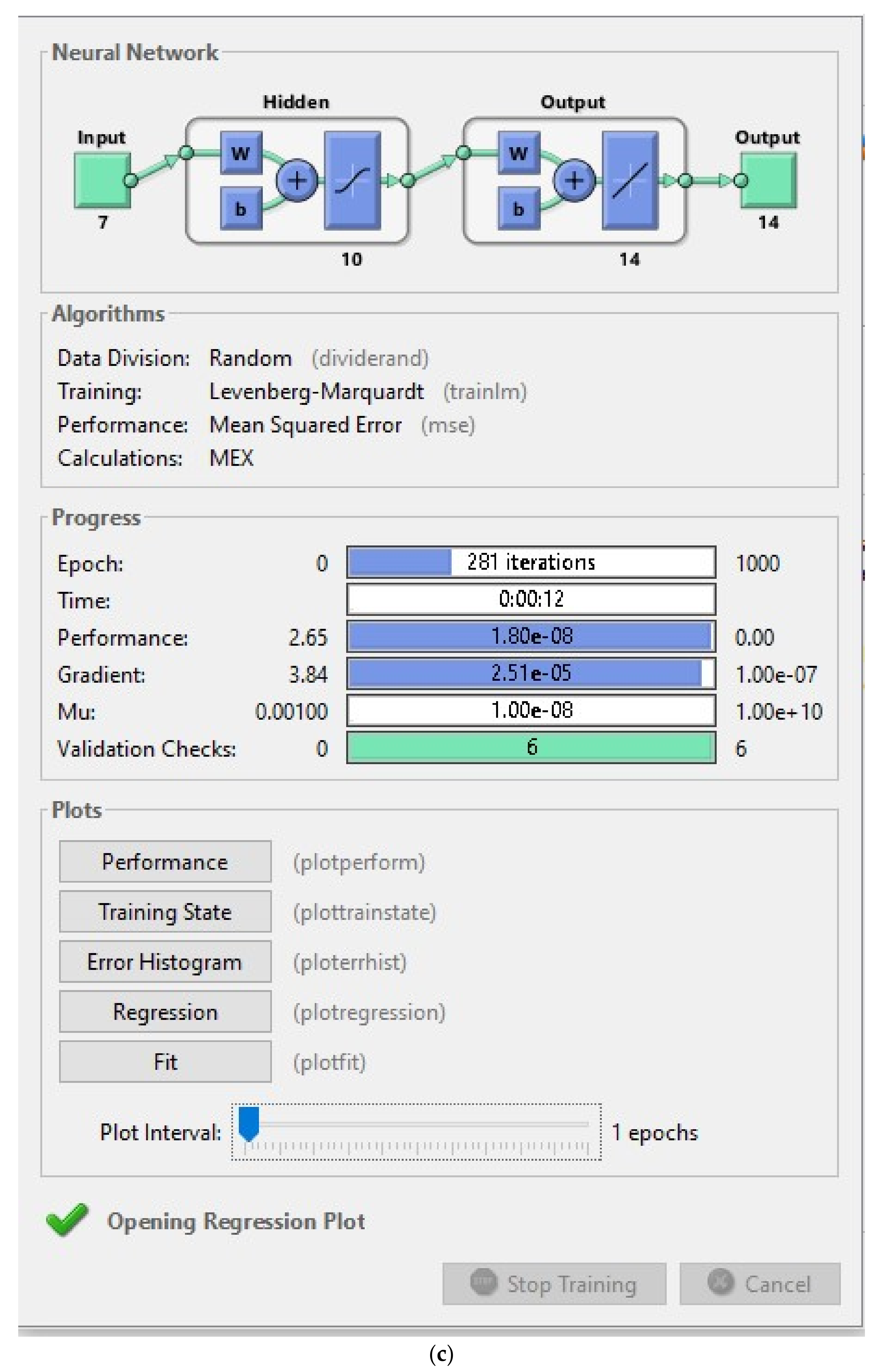
2.4. Configuring the ANN

Figure 7 shows the configuration of the feed-forward backpropagation regressive artificial neural network used in this study. The network was a two-layer feed-forward network with sigmoid hidden neurons and linear output neurons. The construction of the network was carried out by fully connecting the input layer that was made of the geometry parameters and the operating conditions with the output layer that comprised the output power and energy efficiency. The connection of the input layer to the output layer was made possible by using 10 neurons in the hidden layer. In this work, a loss function, the mean squared error (MSE), was used to allow backpropagation in the network. The MSE was defined as the average squared difference between the outputs (ANN predicted values) and the targets (results generated by the ANSYS simulation). Furthermore, the regression R values were used to measure the correlation between the outputs and targets. When R = 1, it means a close relationship, and, when R = 0, it means no relationship or a random relationship. The dataset generated during the ANSYS simulation was divided randomly according to 70%, 15%, and 15% for training, validation, and testing purposes, respectively. The training data were used as inputs to the ANN, and they were used to optimize the network through backpropagation by updating the bias and weights of each neuron. The data partitioned for validation were used to inspect the network, functioning as a check for underfitting or overfitting during training. The test data were entirely new data introduced to the network to check the prediction accuracy of the network after training. The neural network algorithm was developed using the MATLAB platform via the neural fitting tool application. The network was trained using the Levenberg–Marquardt backpropagation algorithm. Further insights into the code used to build the neural network are provided here.

3. Results

This section shows the results that were obtained from the finite element method (FEM)-based optimization of the modified concentrating solar thermoelectric generator with variable area leg geometry. Furthermore, the artificial neural network (ANN)-assisted performance prediction of the device is also shown. Figure 8 shows the characteristics of the neural network model, while Figure 9 shows the FEM-optimized results and the ANN-predicted values. Finally, a comparison is made between the original (unoptimized) parameters and the final (optimized) parameters in Table 4.

4. Discussion

This section discusses the results that were obtained and presented in the previous section. Figure 8a shows that the best validation performance was obtained after 275 iterations. It also shows that the validation error was the highest, followed by the test error and, lastly, the train error. The fact that the test error was higher than the training error shows a good correlation between the input values and the predicted values, as reported by refs. [58,59,60]. This shows that the multilayer perceptron model has a good fitting capacity. Furthermore, as the number of epochs increased beyond 200, the test error seemed to increase a bit, while the train error decreased perpetually, indicating a good fit. A similar observation was also made by ref. [61].
Figure 8b shows the regression plot of the multilayer perceptron ANN model. The plot indicates that the training and testing processes had a perfect correlation of 100%, while the validation process had a high correlation of 99.95%. For all the processes, the regression fidelity was 99.99%, which indicates a very high correlation.
Figure 8c shows the snapshot of the neural network fitting tool in MATLAB software. The network architecture developed in MATLAB is shown. Here, the number of inputs was 7, and the number of outputs was 14. The number of hidden neurons was 10. The seven inputs corresponded to the geometry parameters and the operating conditions that were imposed on the modified TEG in ANSYS, while the 14 outputs corresponded to the seven power outputs and efficiencies obtained as each input was varied. The data division was randomly distributed in a ratio of 2:1:1, while the training algorithm was the Levenberg–Marquardt algorithm. The performance parameter was the mean squared error, and the calculations were carried out using the MEX function in MATLAB. The major results showed that, after 12 s, the neural network achieved a performance of 1.8 × 10⁻⁸ in just six validation checks. Meanwhile, the average time for generating a single datapoint in ANSYS software was 1 min 33 s (93 s). When this was multiplied by seven parameters, 15 datapoints per parameter, this gave a total of 9765 s, which indicated that the neural network was about 800 times faster than the conventional finite element method solver. Similar observations were also reported by previous scholars who showed how much faster and more efficient this method is than the conventional finite element method used to analyze non-segmented, uniform leg thermoelectric generators [62,63,64].
The results in Figure 9 show the neural network fitting of the ANSYS-generated datapoints for each parameter that was varied. Figure 9a displays the effect of increasing the percentage of skutterudite content (while decreasing the bismuth telluride content) on the modified TEG power output and efficiency. The skutterudite content was varied by increasing the n- and p-type hot segment (skutterudite) heights while decreasing the cold segment (bismuth telluride) heights. The percentage content was calculated using the expression H S K T / H T E × 100 . The plot shows that the maximum power and efficiency were obtained at optimum percentage skutterudite contents. It was also noticed that the optimum skutterudite content for maximum power was slightly lower than that for maximum efficiency. This means that, unlike the 50% skutterudite and bismuth telluride contents in the conventional segmented thermoelectric generator, the optimum skutterudite content for maximum efficiency was 37%, while that for maximum power was 25%. Similar to this work, Shittu et al. [30] also reported the effects of optimizing the skutterudite–bismuth telluride ratio so as to maximize the energy efficiency of segmented thermoelectric generators.
Figure 9b shows the variation of the modified device power and efficiency as the thermoelectric leg height was increased sequentially. The plot shows that as the thermoelectric leg height increased, the device power and efficiency increased as well, then attained a maximum value and was followed by a rapid decline even as the leg height increased. This connotes that, for a concentrated solar thermoelectric generator, there exists an optimum leg height that can produce maximum power and efficiency in the device. The original leg height was 1.62 mm; however, from the plots, it can be seen that the maximum power and efficiency were obtained at an optimum leg height of 3.2 mm. Additionally, Figure 9c also shows that the maximum power and efficiency were obtained when optimum leg cross-sectional areas were used. The thermoelectric leg area was varied by altering the thermoelectric leg width, then the resulting cross-sectional area was determined. The plot shows that the optimum areas needed to produce maximum power and efficiencies were 0.25 mm2 and 0.36 mm2, respectively. The reason for the parabolic relationship between the thermoelectric leg heights/areas and the power/efficiency is that, as the height/area was varied, the corresponding temperatures in the device changed as well. These temperatures exerted notable influences on the temperature-dependent material properties of the device which, in turn, determined the power and efficiency of the device. Previous works [21,65,66,67] have also shown similar effects of the thermoelement height and cross-sectional area on device power and efficiency when operated under various thermal operating conditions, indicating that optimum heights and cross-sectional areas are necessary to maximize device performance.
After the optimum device geometry parameters were obtained, the optimum operating conditions were investigated. Figure 9d shows the impact of concentrated solar irradiance on the device power output and efficiencies. The plot shows that the peak power and efficiency were obtained at different optimum concentrated solar irradiances. It was noted that the peak power and efficiency were obtained at optimum concentrated solar irradiances of 336 suns and 279 suns, respectively. This means that a higher power output was needed to further maximize the device power output. In comparison to the original concentrated solar irradiance of 250 suns, the optimums for maximum power and efficiency greatly differed. The results of varying the optimum solar flux on the device performance significantly agreed with the experimental and theoretical works of previous scholars [52,68,69]. Figure 9e further shows the effects of convective cooling heat transfer coefficients on the device power and efficiencies. The plot shows that as long as the cold junction convective film coefficient was increasing, the device power and efficiencies always increased. This is due to the higher rate of thermal energy outflow from the device cold junction for a constant heat inflow. However, it was noted that the device power and efficiency experienced the highest increase when the convective film coefficient increased from 200 W/m2K to 700 W/m2K. As the convective film coefficient was further increased beyond 700 W/m2K, the increase in the power and efficiency began to increase. This can be explained by considering the inherent thermal resistance of the cold junction alumina material. The implication of this result is that achieving higher heat transfer coefficients comes with a higher cost since forced convective media, such as fans and blowers, are required. Therefore, economic considerations must be made regarding the type of cooling media to be used in operating thermoelectric generators. The advantages of higher convective film coefficients on the system efficiency and power production have been shown in these works [70,71,72] with negligible increases in the system performance even as the heat transfer coefficients are further increased. Finally, Figure 9f,g shows the dependence of wind speed and ambient temperature on the device power and efficiency. It is evident from both plots that the device power and efficiency decreased as the wind speed and ambient temperature increased. The reason for this is that a higher wind speed decreases the amount of thermal energy that can be held at the device hot junction, which reduces the device temperature difference and, ultimately, device power output and efficiency. Similarly, a higher ambient temperature leads to a higher heating effect on the device, which limits the amount of thermal spread between the device hot and cold junctions, thus, decreasing the obtainable device temperature difference and power/efficiency. Therefore, for maximum device performance, it is preferrable to operate concentrating solar thermoelectric generators in regions where the wind speed and ambient temperature are low, in agreement with similar works on the effects of environmental parameters on the performance of solar thermoelectric generating systems [30,52,73].
Overall, the results indicate that the multilayer perceptron neural network provided an almost perfect fitting with the ANSYS-generated results. After the training, the neural network codes were exported to a live script that can be used to predict the performance of any thermoelectric generator given some initial inputs and outputs. This means that the neural network can provide a much faster and efficient means of predicting the performance of a modified thermoelectric device compared to the conventional, time-consuming finite element method, which agrees with the previous works of other scholars who focused on the traditional device design [35,59,61,74]. Therefore, it is strongly encouraged that thermoelectric generator designing companies such as Kryotherm adopt the neural network fitting method in predicting the performance of thermoelectric devices since it can facilitate the quick design and production of high-performing thermoelectric devices.
To estimate the significance of optimizing the geometry parameters and operating conditions of the new device design, Table 4 shows a comparison between the initial and optimized parameters for maximum device efficiency. The table shows that the calculated optimum parameters were very different from the initial parameters and conditions used to model the device as specified by the manufacturers and operators. More importantly, it was noted that the device had a power and efficiency of 0.05 W and 4%, respectively, when the original/initial parameters were used. However, after optimizing the device performance, the maximum power and efficiency obtained were 0.14 W and 8%, respectively, when the optimum parameters were used. This signifies that the optimization doubled the device efficiency, while the power output was almost tripled, hence, showing the efficacy of the optimization carried out in this work. This agrees with the findings of previous scholars [65,75,76], who showed the higher efficiencies and power outputs obtained after optimization was conducted on the thermoelements’ geometry and thermal operating conditions.

5. Conclusions

In this research work, the finite-element-method-based design of a new concentrating solar thermoelectric generator design (segmented variable area leg) was carried out using ANSYS software. After the device was designed, the comprehensive optimization of the geometry parameters, as well as the operating conditions, was carried out. Then, a multilayer perceptron regressive artificial neural network was developed using the MATLAB neural network fitting tool application to overcome the high computational energy and time requirements of the ANSYS finite-element-based solver. At the end, the efficacy of the optimization process was determined by comparing the power and efficiency of the optimized device and the original (unoptimized) device. Among the several interesting results obtained, the following important conclusions were made:
  • The optimum parameters for maximum device power and efficiency were calculated and obtained by using a verified finite element method developed in ANSYS. The optimum parameters were very different from the original operating parameters that were specified by the manufacturers and device operators. At the end of the optimization, the performance of the original device and the optimized device were compared, and it was found that the power and efficiency of the optimized device were 3 × and 2 × higher than that of the original device, respectively;
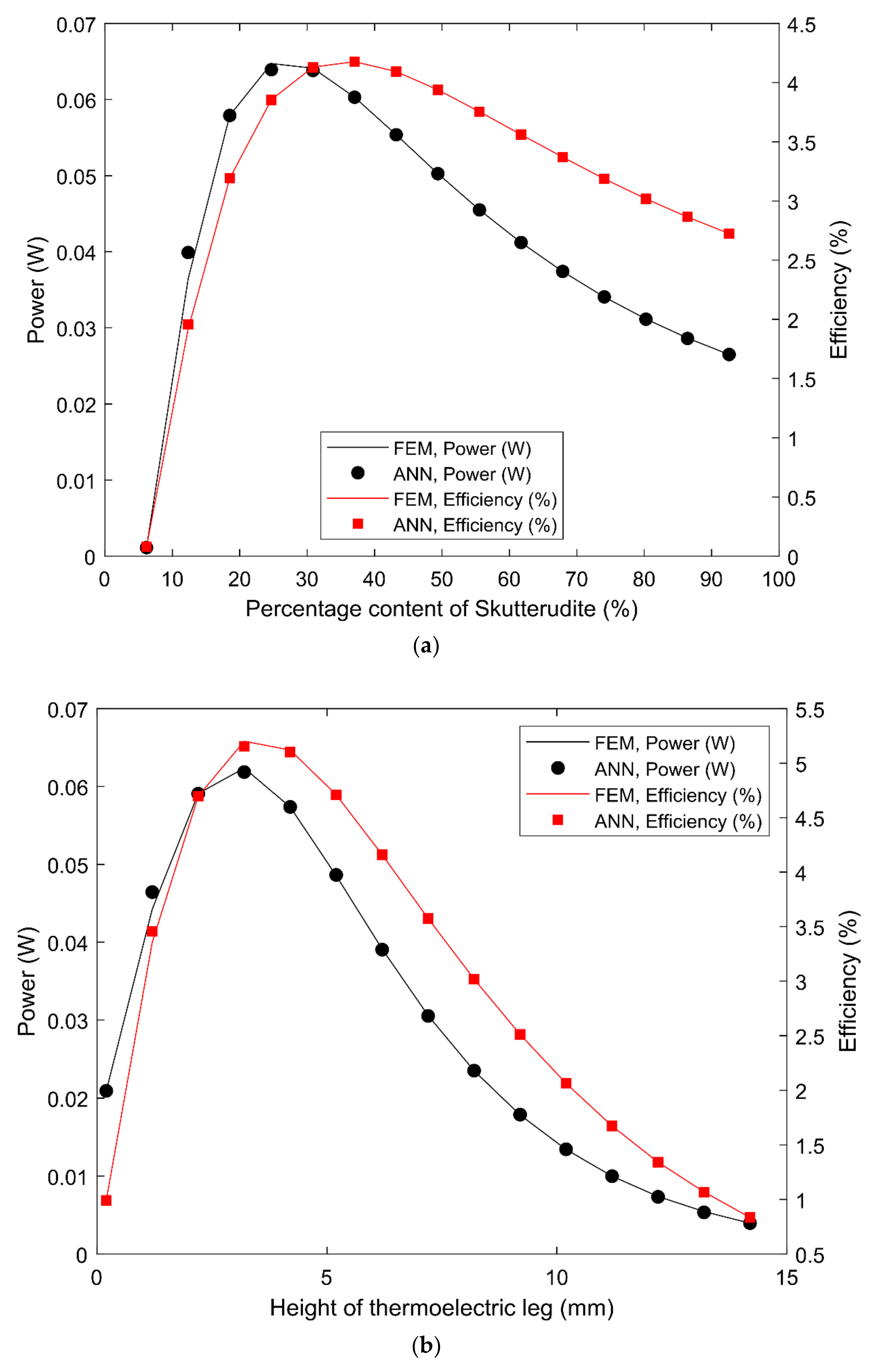
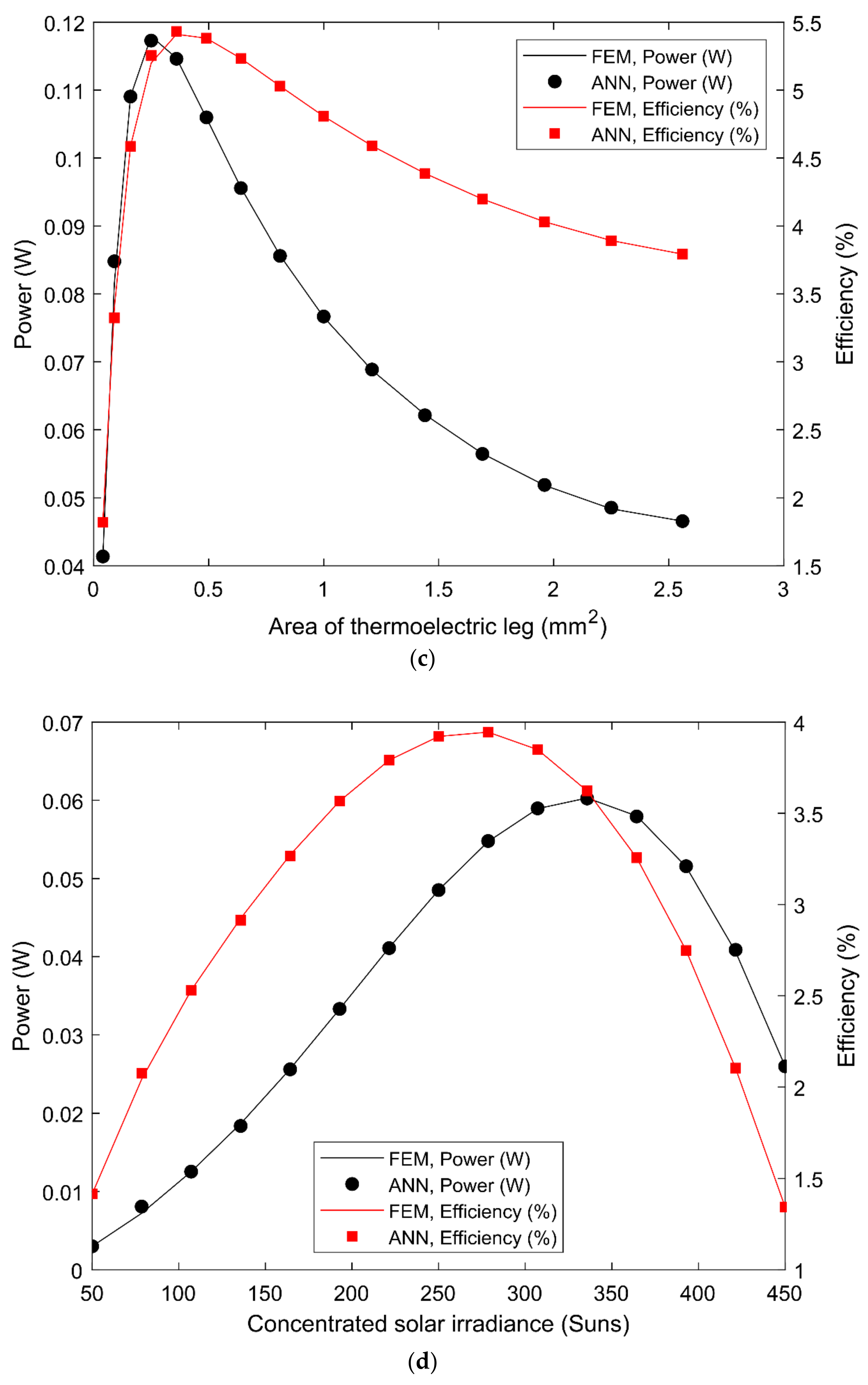
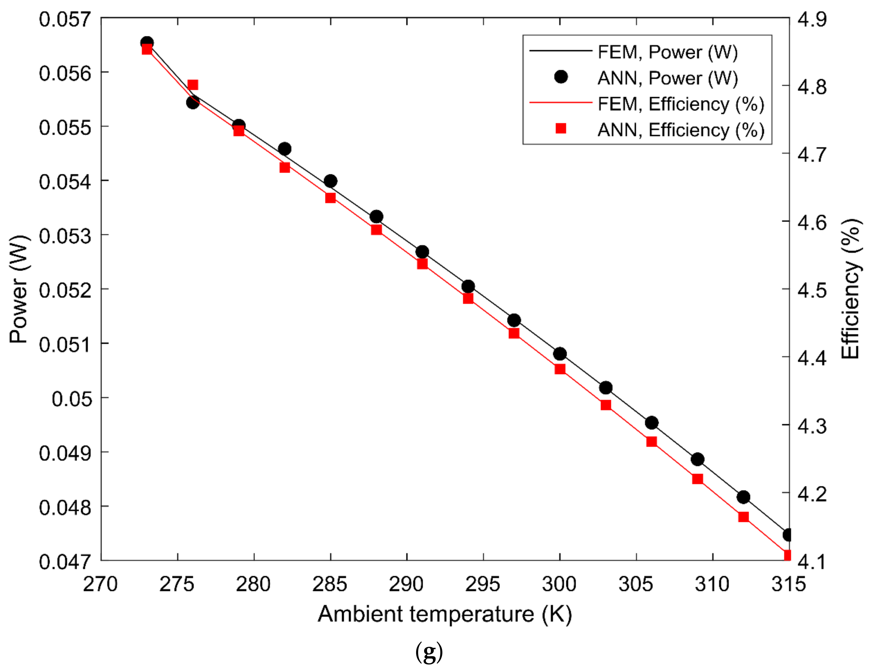
  • The multilayer perceptron regressive artificial neural network built using MATLAB codes was found to be very accurate in learning the data generated by the finite element method. The training, testing, and validation regression were 100%, 100%, and 99.95%, respectively. Furthermore, it was found that the best validation loss function (mean squared error) of 0.004 was obtained after 275 iterations. Additionally, the lowest mean squared error of 1.8 × 10⁻⁸ was obtained during the training process. Most importantly, it was shown that the neural network perfectly learnt the finite element data in just 12 s, which was more than 800 × faster than the finite-element-method-based solver. Therefore, the neural network fitting approach is more efficient in predicting the performance of any thermoelectric generator given some predefined input, thus, facilitating the fast production of high-performing thermoelectric devices;
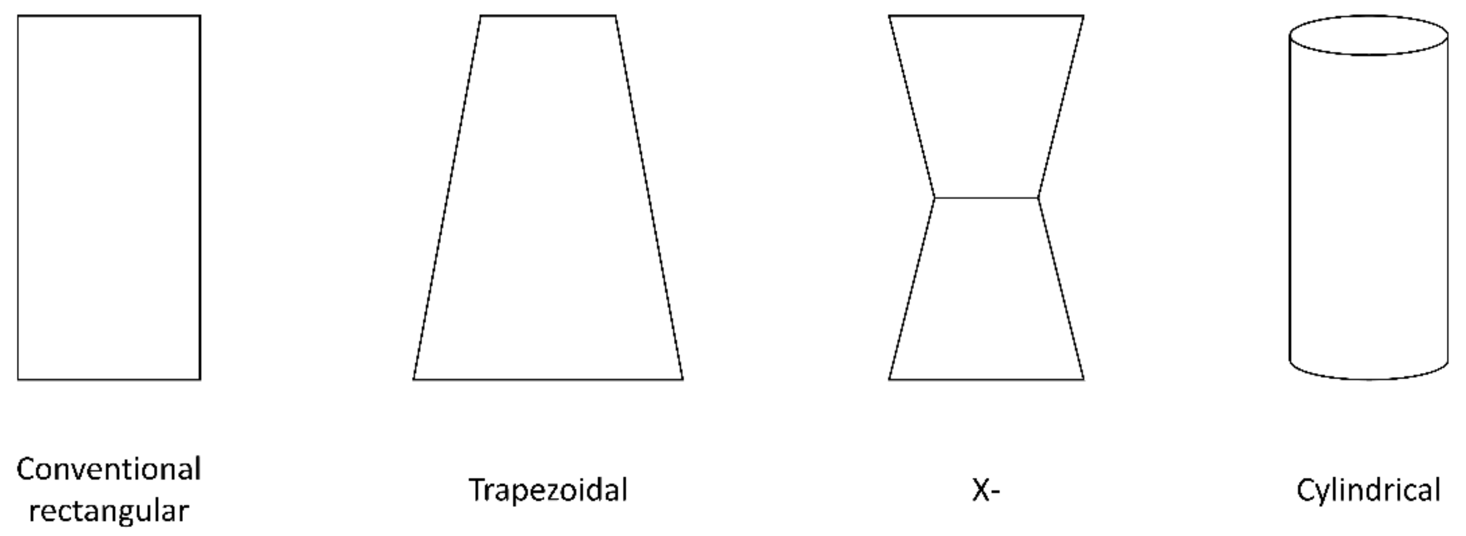
  • Many interesting findings were uncovered in this study; however, there is always room for future studies in every good research endeavor. The next study will seek to model a fully modified thermoelectric device made of several thermoelectric cells to find the optimum number of couples that produces the highest performance in the modified device design. After that, a neural network fitting approach will be introduced to quickly facilitate the ease and speed at which optimization information can be drawn to model very efficient, high-performing thermoelectric devices. Thereafter, the operational lifetime of a circular leg thermoelectric generator and the proposed trapezoidal leg thermoelectric generator will be compared when operated under the same solar flux boundary conditions.

Author Contributions

Conceptualization, methodology, software, validation, formal analysis, investigation, resources, data curation, writing—original draft preparation, C.M., H.F. and I.A.; writing—review and editing, M.A.; visualization, H.F.; supervision, project administration, C.M.; funding acquisition, H.F., I.A. and M.A. All authors have read and agreed to the published version of the manuscript.

Funding

This paper is part of a research project funded by the Office of Research and Sponsored Programs (ORSP) at Abu Dhabi University through a research fund (Grant number 19300638).

Data Availability Statement

The data used in this manuscript are available upon reasonable request from the corresponding author.

Conflicts of Interest

The authors declare no conflict of interest.

References

  1. Anaadumba, R.; Liu, Q.; Marah, B.D.; Nakoty, F.M.; Liu, X.; Zhang, Y. A Renewable Energy Forecasting and Control Approach to Secured Edge-Level Efficiency in a Distributed Micro-Grid. Cybersecurity 2021, 4, 1. [Google Scholar] [CrossRef]
  2. Ozoegwu, C.G. The Solar Energy Assessment Methods for Nigeria: The Current Status, the Future Directions and a Neural Time Series Method. Renew. Sustain. Energy Rev. 2020, 92, 146–159. [Google Scholar] [CrossRef]
  3. Li, M.; Xu, S.; Chen, Q.; Zheng, L.-R. Thermoelectric-Generator-Based DC–DC Conversion Networks for Automotive Applications. J. Electron. Mater. 2011, 40, 1136–1143. [Google Scholar] [CrossRef]
  4. Wu, S.; Zhang, Y.-C.; Xiao, L. Conceptual Design and Performance Analysis of Concentrated Solar-Driven TIC/AMTEC/TEG Hybrid System. Int. J. Energy Res. 2018, 42, 4674–4686. [Google Scholar] [CrossRef]
  5. Najafi, H.; Woodbury, K.A. Optimization of a Cooling System Based on Peltier Effect for Photovoltaic Cells. Sol. Energy 2013, 91, 152–160. [Google Scholar] [CrossRef]
  6. Rowe, D.M. Thermoelectrics, an Environmentally-Friendly Source of Electrical Power. Renew. Energy 1999, 16, 1251–1256. [Google Scholar] [CrossRef]
  7. Lee, H. Thermoelectrics, 1st ed.; John Wiley & Sons Ltd.: West Sussex, UK, 2017; ISBN 9781118848951. [Google Scholar]
  8. Shi, Y.; Wang, Y.; Mei, D.; Feng, B.; Chen, Z. Design and Fabrication of Wearable Thermoelectric Generator Device for Heat Harvesting. IEEE Robot. Autom. Lett. 2018, 3, 373–378. [Google Scholar] [CrossRef]
  9. Zheng, X.F.; Liu, C.X.; Yan, Y.Y.; Wang, Q. A Review of Thermoelectrics Research—Recent Developments and Potentials for Sustainable and Renewable Energy Applications. Renew. Sustain. Energy Rev. 2014, 32, 486–503. [Google Scholar] [CrossRef]
  10. Patil, M.S.; Seo, J.-H.; Lee, M.-Y. Numerical Study on Geometric Parameter Effects of Power Generation Performances for Segmented Thermoelectric Generator. Int. J. Air-Cond. Refrig. 2018, 26, 1850004. [Google Scholar] [CrossRef]
  11. Hong, M.; Zheng, K.; Lyv, W.; Li, M.; Qu, X.; Sun, Q.; Xu, S.; Zou, J.; Chen, Z.-G. Computer-Aided Design of High-Efficiency GeTe-Based Thermoelectric Devices. Energy Environ. Sci. 2020, 13, 1856–1864. [Google Scholar] [CrossRef]
  12. Khan, A.U.; Kobayashi, K.; Tang, D.M.; Yamauchi, Y.; Hasegawa, K.; Mitome, M.; Xue, Y.; Jiang, B.; Tsuchiya, K.; Golberg, D.; et al. Nano-Micro-Porous Skutterudites with 100% Enhancement in ZT for High Performance Thermoelectricity. Nano Energy 2017, 31, 152–159. [Google Scholar] [CrossRef]
  13. Ghomian, T.; Kizilkaya, O.; Domulevicz, L.K.; Hihath, J. Molecular Quantum Interference Effects on Thermopower in Hybrid 2-Dimensional Monolayers. Nanoscale 2022, 14, 6248–6257. [Google Scholar] [CrossRef]
  14. Ghomian, T.; Mehraeen, S. Survey of Energy Scavenging for Wearable and Implantable Devices. Energy 2019, 178, 33–49. [Google Scholar] [CrossRef]
  15. Ghomian, T.; Darwish, N.; Hihath, J. Thickness-Dependent Seebeck Coefficient in Hybrid 2-Dimensional Layers. In Proceedings of the 2021 IEEE 16th Nanotechnology Materials and Devices Conference (NMDC), Vancouver, BC, Canada, 12–15 December 2021; pp. 1–4. [Google Scholar] [CrossRef]
  16. Şişik, B.; LeBlanc, S. The Influence of Leg Shape on Thermoelectric Performance Under Constant Temperature and Heat Flux Boundary Conditions. Front. Mater. 2020, 7, 595955. [Google Scholar] [CrossRef]
  17. Pina, A.; Ferrão, P.; Fournier, J.; Lacarrière, B.; Corre, O. Le Optimizing on Thermoelectric Elements Footprint of the for Maximum Power Generation Assessing the Guiqiang Feasibility of Using the Jin Heat Temperature Function District Forecast. Energy Procedia 2017, 142, 730–735. [Google Scholar] [CrossRef]
  18. Ibeagwu, O.I. Modelling and Comprehensive Analysis of TEGs with Diverse Variable Leg Geometry. Energy 2019, 180, 90–106. [Google Scholar] [CrossRef]
  19. Olivares-Robles, M.A.; Badillo-Ruiz, C.A.; Ruiz-Ortega, P.E. A Comprehensive Analysis on Nanostructured Materials in a Thermoelectric Micro-System Based on Geometric Shape, Segmentation Structure and Load Resistance. Sci. Rep. 2020, 10, 21659. [Google Scholar] [CrossRef]
  20. Wang, R.; Meng, Z.; Luo, D.; Yu, W.; Zhou, W. A Comprehensive Study on X-Type Thermoelectric Generator Modules. J. Electron. Mater. 2020, 49, 4343–4354. [Google Scholar] [CrossRef]
  21. Ranjan, M.; Maiti, T. Device Modeling and Performance Optimization of Thermoelectric Generators under Isothermal and Isoflux Heat Source Condition. J. Power Sources 2020, 480, 228867. [Google Scholar] [CrossRef]
  22. Ali, H.; Yilbas, B.S.; Al-Sharafi, A. Segmented Thermoelectric Generator: Exponential Area Variation in Leg. Int. J. Energy Res. 2018, 42, 477–489. [Google Scholar] [CrossRef]
  23. Thimont, Y.; LeBlanc, S. The Impact of Thermoelectric Leg Geometries on Thermal Resistance and Power Output. J. Appl. Phys. 2019, 126, 095101. [Google Scholar] [CrossRef]
  24. Maduabuchi, C.; Njoku, H.; Eke, M.; Mgbemene, C.; Lamba, R.; Ibrahim, J.S. Overall Performance Optimisation of Tapered Leg Geometry Based Solar Thermoelectric Generators under Isoflux Conditions. J. Power Sources 2021, 500, 229989. [Google Scholar] [CrossRef]
  25. Maduabuchi, C.; Lamba, R.; Njoku, H.; Eke, M.; Mgbemene, C. Effects of Leg Geometry and Multistaging of Thermoelectric Modules on the Performance of a Photovoltaic-thermoelectric System Using Different Photovoltaic Cells. Int. J. Energy Res. 2021, 45, 17888–17902. [Google Scholar] [CrossRef]
  26. Yamada, T.; Miyazaki, Y.; Yamane, H. Preparation of Higher Manganese Silicide (HMS) Bulk and Fe-Containing HMS Bulk Using a Na-Si Melt and Their Thermoelectrical Properties. Thin Solid Films 2011, 519, 8524–8527. [Google Scholar] [CrossRef]
  27. Barber, E. Thermoelectric Materials; Taylor & Francis Group: Boca Raton, FL, USA, 2015; ISBN 9789814463539. [Google Scholar]
  28. Lee, M.-Y.; Seo, J.; Lee, H.; Garud, K.S. Power Generation, Efficiency and Thermal Stress of Thermoelectric Module with Leg Geometry, Material, Segmentation and Two-Stage Arrangement. Symmetry 2020, 12, 786. [Google Scholar] [CrossRef]
  29. Su, Q.; Engel, D.T.G. Modeling and Simulation of a Segmented Thermoelectric Generator. Ph.D. Thesis, University of Missouri, Columbia, IN, USA, 2017. [Google Scholar]
  30. Shittu, S.; Li, G.; Xuan, Q.; Zhao, X.; Ma, X.; Cui, Y. Electrical and Mechanical Analysis of a Segmented Solar Thermoelectric Generator under Non-Uniform Heat Flux. Energy 2020, 199, 117433. [Google Scholar] [CrossRef]
  31. Cui, Y.J.; Wang, B.L.; Li, J.E.; Wang, K.F. Performance Evaluation and Lifetime Prediction of a Segmented Photovoltaic-Thermoelectric Hybrid System. Energy Convers. Manag. 2020, 211, 112744. [Google Scholar] [CrossRef]
  32. Liu, H.B.; Meng, J.H.; Wang, X.D.; Chen, W.H. A New Design of Solar Thermoelectric Generator with Combination of Segmented Materials and Asymmetrical Legs. Energy Convers. Manag. 2018, 175, 11–20. [Google Scholar] [CrossRef]
  33. Fan, S.; Gao, Y. Numerical Analysis on the Segmented Annular Thermoelectric Generator for Waste Heat Recovery. Energy 2019, 183, 35–47. [Google Scholar] [CrossRef]
  34. Ruiz-Ortega, P.E.; Olivares-Robles, M.A.; Badillo-Ruiz, C.A. Transient Thermal Behavior of a Segmented Thermoelectric Cooler with Variable Cross-Sectional Areas. Int. J. Energy Res. 2021, 45, 19215–19225. [Google Scholar] [CrossRef]
  35. Kishore, R.; Mahajan, R.; Priya, S. Combinatory Finite Element and Artificial Neural Network Model for Predicting Performance of Thermoelectric Generator. Energies 2018, 11, 2216. [Google Scholar] [CrossRef]
  36. Lee, Y.; Tay, A.A.O. Stress Analysis of Silicon Wafer-Based Photovoltaic Modules Under IEC 61215 Mechanical Load Test. In Proceedings of the PV Asia Pacific Conference, Marine Bay Sands, Singapore, 29–30 October 2013; Volume 33, pp. 265–271. [Google Scholar]
  37. Fagehi, H.; Attar, A.; Lee, H. Optimal Design of an Automotive Exhaust Thermoelectric Generator. J. Electron. Mater. 2018, 47, 3983–3995. [Google Scholar] [CrossRef]
  38. Elarusi, A.H.; Fagehi, H.; Lee, H.; Attar, A. Theoretical Approach to Predict the Performance of Thermoelectric Generator Modules. J. Electron. Mater. 2017, 46, 872–881. [Google Scholar] [CrossRef]
  39. Lamba, R.; Manikandan, S.; Kaushik, S.C.; Tyagi, S.K. Thermodynamic Modelling and Performance Optimization of Trapezoidal Thermoelectric Cooler Using Genetic Algorithm. Therm. Sci. Eng. Prog. 2018, 6, 236–250. [Google Scholar] [CrossRef]
  40. Maduabuchi, C. Thermo-Mechanical Optimization of Thermoelectric Generators Using Deep Learning Artificial Intelligence Algorithms Fed with Verified Finite Element Simulation Data. Appl. Energy 2022, 315, 118943. [Google Scholar] [CrossRef]
  41. Mazzeo, D.; Herdem, M.S.; Matera, N.; Bonini, M.; Wen, J.Z.; Nathwani, J.; Oliveti, G. Artificial Intelligence Application for the Performance Prediction of a Clean Energy Community. Energy 2021, 232, 120999. [Google Scholar] [CrossRef]
  42. Notton, G.; Cristofari, C.; Mattei, M.; Poggi, P. Modelling of a Double-Glass Photovoltaic Module Using Finite Differences. Appl. Therm. Eng. 2005, 25, 2854–2877. [Google Scholar] [CrossRef]
  43. Chen, W.; Chiou, Y. Geometry Design for Maximizing Output Power of Segmented Skutterudite Thermoelectric Generator by Evolutionary Computation. Appl. Energy 2020, 274, 115296. [Google Scholar] [CrossRef]
  44. He, H.; Liu, W.; Wu, Y.; Rong, M.; Zhao, P.; Tang, X. An Approximate and Efficient Characterization Method for Temperature-Dependent Parameters of Thermoelectric Modules. Energy Convers. Manag. 2019, 180, 584–597. [Google Scholar] [CrossRef]
  45. Shittu, S.; Li, G.; Zhao, X.; Ma, X.; Golizadeh, Y.; Fan, Y. Comprehensive Study and Optimization of Concentrated Photovoltaic- Thermoelectric Considering All Contact Resistances. Energy Convers. Manag. 2020, 205, 112422. [Google Scholar] [CrossRef]
  46. Xuan, X.; Ng, K.; Yap, C.; Chua, H. The Maximum Temperature Difference and Polar Characteristic of Two-Stage Thermoelectric Coolers. Cryogenics 2002, 42, 273–278. [Google Scholar] [CrossRef]
  47. Maduabuchi, C.C.; Mgbemene, C.A. Numerical Study of a Phase Change Material Integrated Solar Thermoelectric Generator. J. Electron. Mater. 2020, 49, 5917–5936. [Google Scholar] [CrossRef]
  48. Maduabuchi, C.C.; Mgbemene, C.A.; Ibeagwu, O.I. Thermally Induced Delamination of PV-TEG: Implication of Leg’s Joule and Thomson Heating. J. Electron. Mater. 2020, 49, 6417–6427. [Google Scholar] [CrossRef]
  49. Shittu, S.; Li, G.; Zhao, X.; Ma, X.; Akhlaghi, Y.G.; Ayodele, E. High Performance and Thermal Stress Analysis of a Segmented Annular Thermoelectric Generator. Energy Convers. Manag. 2019, 184, 180–193. [Google Scholar] [CrossRef]
  50. Kraemer, D.; Jie, Q.; McEnaney, K.; Cao, F.; Liu, W.; Weinstein, L.A.; Loomis, J.; Ren, Z.; Chen, G. Concentrating Solar Thermoelectric Generators with a Peak Efficiency of 7.4%. Nat. Energy 2016, 1, 16153. [Google Scholar] [CrossRef]
  51. Maduabuchi, C.C.; Eke, M.N.; Mgbemene, C.A. Solar Power Generation Using a Two-stage X-leg Thermoelectric Generator with High-temperature Materials. Int. J. Energy Res. 2021, 45, 13163–13181. [Google Scholar] [CrossRef]
  52. Lamba, R.; Manikandan, S.; Kaushik, S.C. Performance Analysis and Optimization of Concentrating Solar Thermoelectric Generator. J. Electron. Mater. 2018, 47, 5310–5320. [Google Scholar] [CrossRef]
  53. Luo, Y.; Kim, C.N. Effects of the Cross-Sectional Area Ratios and Contact Resistance on the Performance of a Cascaded Thermoelectric Generator. Int. J. Energy Res. 2019, 43, 2172–2187. [Google Scholar] [CrossRef]
  54. Karri, N.K.; Mo, C. Structural Reliability Evaluation of Thermoelectric Generator Modules: Influence of End Conditions, Leg Geometry, Metallization, and Processing Temperatures. J. Electron. Mater. 2018, 47, 6101–6120. [Google Scholar] [CrossRef]
  55. Li, W.; Paul, M.C.; Montecucco, A.; Knox, A.R.; Siviter, J.; Sellami, N.; Meng, X.; Fernandez, E.F.; Mallick, T.K.; Mullen, P.; et al. Multiphysics Simulations of a Thermoelectric Generator. Energy Procedia 2015, 75, 633–638. [Google Scholar] [CrossRef]
  56. Erturun, U.; Erermis, K.; Mossi, K. Influence of Leg Sizing and Spacing on Power Generation and Thermal Stresses of Thermoelectric Devices. Appl. Energy 2015, 159, 19–27. [Google Scholar] [CrossRef]
  57. Wang, X.; Qi, J.; Deng, W.; Li, G.; Gao, X.; He, L.; Zhang, S. An Optimized Design Approach Concerning Thermoelectric Generators with Frustum-Shaped Legs Based on Three-Dimensional Multiphysics Model. Energy 2021, 233, 120810. [Google Scholar] [CrossRef]
  58. Sarker, I.H. Deep Learning: A Comprehensive Overview on Techniques, Taxonomy, Applications and Research Directions. SN Comput. Sci. 2021, 2, 420. [Google Scholar] [CrossRef]
  59. Wang, P.; Wang, K.; Xi, L.; Gao, R.; Wang, B. Fast and Accurate Performance Prediction and Optimization of Thermoelectric Generators with Deep Neural Networks. Adv. Mater. Technol. 2021, 6, 2100011. [Google Scholar] [CrossRef]
  60. Pang, Z.; Niu, F.; O’Neill, Z. Solar Radiation Prediction Using Recurrent Neural Network and Artificial Neural Network: A Case Study with Comparisons. Renew. Energy 2020, 156, 279–289. [Google Scholar] [CrossRef]
  61. Garud, K.S.; Seo, J.-H.; Cho, C.-P.; Lee, M.-Y. Artificial Neural Network and Adaptive Neuro-Fuzzy Interface System Modelling to Predict Thermal Performances of Thermoelectric Generator for Waste Heat Recovery. Symmetry 2020, 12, 259. [Google Scholar] [CrossRef]
  62. Demeke, W.; Kim, Y.; Jung, J.; Chung, J.; Ryu, B.; Ryu, S. Neural Network-Assisted Optimization of Segmented Thermoelectric Power Generators Using Active Learning Based on a Genetic Optimization Algorithm. Energy Rep. 2022, 8, 6633–6644. [Google Scholar] [CrossRef]
  63. Zhu, Y.; Newbrook, D.W.; Dai, P.; de Groot, C.H.K.; Huang, R. Artificial Neural Network Enabled Accurate Geometrical Design and Optimisation of Thermoelectric Generator. Appl. Energy 2022, 305, 117800. [Google Scholar] [CrossRef]
  64. Kim, T.Y. Prediction of System-Level Energy Harvesting Characteristics of a Thermoelectric Generator Operating in a Diesel Engine Using Artificial Neural Networks. Energies 2021, 14, 2426. [Google Scholar] [CrossRef]
  65. Cai, L.; Li, P.; Luo, Q.; Zhai, P.; Zhang, Q. Geometry Optimization of a Segmented Thermoelectric Generator Based on Multi-Parameter and Nonlinear Optimization Method. J. Electron. Mater. 2017, 46, 1552–1566. [Google Scholar] [CrossRef]
  66. Yin, T.; Li, W.-T.; Li, K.; He, Z.-Z. Multi-Parameter Optimization and Uncertainty Analysis of Multi-Stage Thermoelectric Generator with Temperature-Dependent Materials. Energy Rep. 2021, 7, 7212–7223. [Google Scholar] [CrossRef]
  67. Li, G.; Shittu, S.; Ma, X.; Zhao, X. Comparative Analysis of Thermoelectric Elements Optimum Geometry between Photovoltaic-Thermoelectric and Solar Thermoelectric. Energy 2019, 171, 599–610. [Google Scholar] [CrossRef]
  68. Sun, D.; Shen, L.; Yao, Y.; Chen, H.; Jin, S.; He, H. The Real-Time Study of Solar Thermoelectric Generator. Appl. Therm. Eng. 2017, 119, 347–359. [Google Scholar] [CrossRef]
  69. Mahmoudinezhad, S.; Rezania, A.; Cotfas, P.A.; Cotfas, D.T.; Rosendahl, L.A. Transient Behavior of Concentrated Solar Oxide Thermoelectric Generator. Energy 2018, 168, 823–832. [Google Scholar] [CrossRef]
  70. Cheruvu, P.; Kumar, V.P.; Barshilia, H.C. Experimental Analysis and Evaluation of a Vacuum Enclosed Concentrated Solar Thermoelectric Generator Coupled with a Spectrally Selective Absorber Coating. Int. J. Sustain. Energy 2017, 37, 782–798. [Google Scholar] [CrossRef]
  71. Mahmoudinezhad, S.; Rezaniakolaei, A.; Rosendahl, L.A. Numerical Parametric Study on the Performance of CPV-TEG Hybrid System. Energy Procedia 2019, 158, 453–458. [Google Scholar] [CrossRef]
  72. Ziolkowski, P.; Zabrocki, K.; Müller, E. TEG Design for Waste Heat Recovery at an Aviation Jet Engine Nozzle. Appl. Sci. 2018, 8, 2637. [Google Scholar] [CrossRef]
  73. Maduabuchi, C. Improving the Performance of a Solar Thermoelectric Generator Using Nano-Enhanced Variable Area Pins. Appl. Therm. Eng. 2022, 206, 118086. [Google Scholar] [CrossRef]
  74. Angeline, A.A.; Asirvatham, L.G.; Hemanth, D.J.; Jayakumar, J.; Wongwises, S. Performance Prediction of Hybrid Thermoelectric Generator with High Accuracy Using Artificial Neural Networks. Sustain. Energy Technol. Assess. 2019, 33, 53–60. [Google Scholar] [CrossRef]
  75. Maduabuchi, C.; Singh, S.; Ozoegwu, C.; Njoku, H.; Eke, M. The Combined Impacts of Leg Geometry Configuration and Multi-Staging on the Exergetic Performance of Thermoelectric Modules in a Solar Thermoelectric Generator. J. Energy Resour. Technol. 2022, 144, 041303. [Google Scholar] [CrossRef]
  76. Ge, Y.; Lin, Y.; He, Q.; Wang, W.; Chen, J.; Huang, S.M. Geometric Optimization of Segmented Thermoelectric Generators for Waste Heat Recovery Systems Using Genetic Algorithm. Energy 2021, 233, 121220. [Google Scholar] [CrossRef]
Figure 1. Different types of leg geometries that have been studied previously.
Energies 15 06024 g001
Figure 2. Three-dimensional CAD models of the device configuration—segmented variable area pin device thermoelectric generator with the specified boundary conditions in annotations.
Energies 15 06024 g002
Figure 3. Material properties of the high- and low-temperature materials: (a) Seebeck coefficient; (b) electrical resistivity; (c) thermal conductivity; (d) dimensionless figure of merit [43,44].
Energies 15 06024 g003aEnergies 15 06024 g003b
Figure 4. Results of the mesh convergence study.
Energies 15 06024 g004
Figure 5. Mesh and temperature distributions for the extremely fine and coarse meshing. (a,b) extremely fine, (c,d) coarse.
Energies 15 06024 g005aEnergies 15 06024 g005b
Figure 6. Comparison between experimental and finite element results. (a,b) temperature and voltage distributions, (c,d) variation of power and efficiency with device hot junction temperature.
Energies 15 06024 g006
Figure 7. Architecture of the artificial neural network used to predict the device performance. The geometry parameters and device thermal operating conditions made up the input layer, while the outputs were the device power output and energy efficiency.
Energies 15 06024 g007
Figure 8. Characteristics of the regressive ANN model used to predict the TEG performance. (a) mean squared error of the model, (b) regression plot of the model, (c) snapshot of the neural network fitting application after successful training.
Energies 15 06024 g008aEnergies 15 06024 g008b
Figure 9. FEM-based optimization and ANN-informed prediction of the modified TEG device. (a) percentage amount of Skutterudite, (b,c) height and cross-sectional area of thermoelectric legs, (d) concentrated solar irradiance, (e) connective cooling heat transfer coefficient, (f) wind speed, (g) ambient temperature.
Energies 15 06024 g009aEnergies 15 06024 g009bEnergies 15 06024 g009cEnergies 15 06024 g009d
Table 1. Geometry parameters used to develop the TEG CAD model.
S/NComponentHeight (mm)Width (mm)Depth (mm)
1.Hot ceramic plate0.83.10.7
2.Cold ceramic plate0.85.80.7
3.Copper0.23.10.7
4.Solder (small)0.10.70.7
5.Solder (big)0.11.41.4
6.n-p-type (small)1.620.70.7
7.n-p-type (big)1.621.41.4
Table 2. Polynomial expressions describing the material properties of the hot and cold segment thermoelectric materials [43].
PropertyExpression
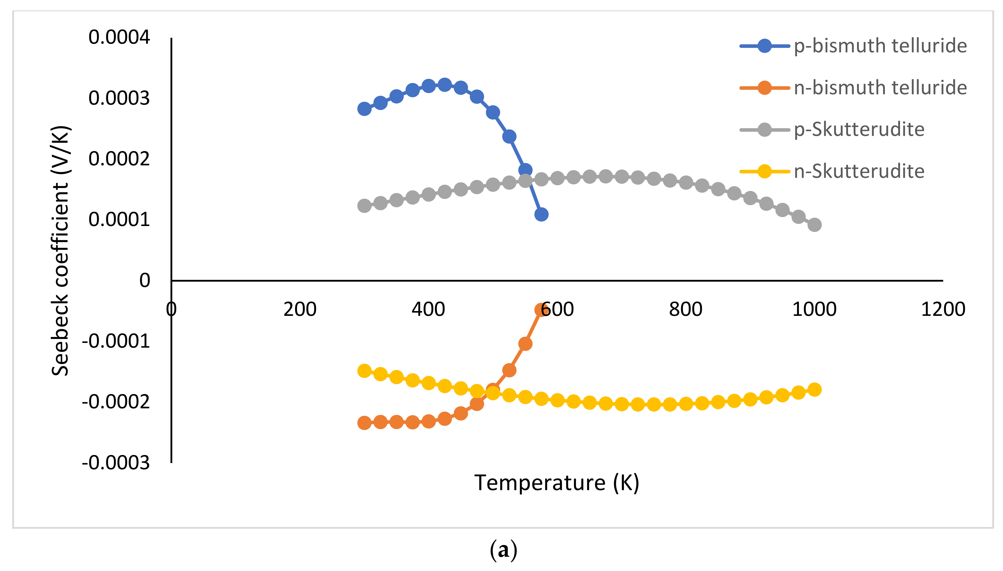
Seebeck coefficient (V/K)
p-BiTe−2.24407 × 10⁻¹¹T3 + 2.22834 × 10⁻⁸T2 − 7.301 × 10⁻⁶T + 1.023898 × 10⁻³
n-BiTe1.68178 × 10−11T3 − 1.77163 × 10⁻⁸T2 + 6.203 × 10⁻⁶T − 9.54589 × 10⁻⁴
p-SKT8.8139 × 10−5 − 3.6827 × 10⁻¹⁰T + 5.5507 × 10⁻¹⁰T2 − 5.0917 × 10⁻¹³T3
n-SKT−7.2398 × 10⁻⁵ − 2.7340 × 10⁻⁷T + 2.4331 × 10⁻¹⁰T2 + 1.4197 × 10⁻¹³T3
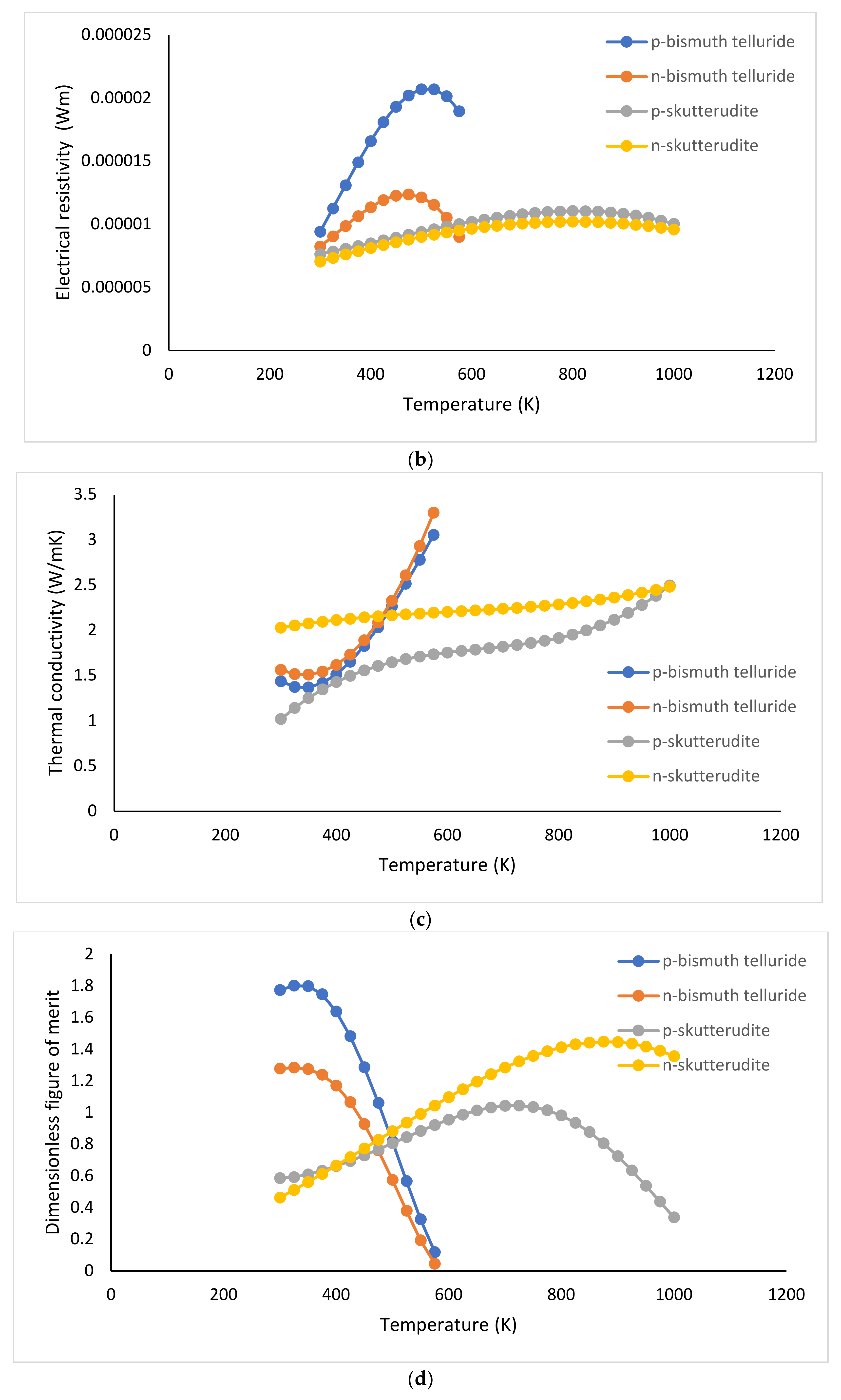
Electrical resistivity (Wm)
p-BiTe−7.75456 × 10⁻¹³T3 + 7.77051 × 10⁻¹⁰T2 − 0.01853 × 10⁻⁵T + 1.60117 × 10⁻⁵
n-BiTe−6.04782 × 10⁻¹³T3 + 6.09155 × 10⁻¹⁰T2 − 1.715 × 10⁻⁷T + 2.11951 × 10⁻⁵
p-SKT6.5155 × 10−6 − 2.3672 × 10⁻⁹T + 2.6624 × 10⁻¹¹T2 − 2.0732 × 10⁻¹⁴T3
n-SKT2.9221 × 10−6 + 1.5542 × 10⁻⁸T − 4.7078 × 10⁻¹²T2 − 4.1703 × 10⁻¹⁵T3
Thermal conductivity (W/mK)
p-BiTe−5.82609 × 10⁻⁸T3 + 1.03491 × 10⁻⁴T2 − 0.05011T + 8.726
n-BiTe3.76869 × 10−9T3 + 2.81722 × 10⁻⁵T2 − 0.02057T + 5.09531
p-SKT−2.0660 + 1.6390 × 10⁻²T − 2.4031 × 10⁻⁵T2 + 1.2202 × 10⁻⁸T3
n-SKT1.4464 + 3.0553 × 10⁻³T − 4.4576 × 10⁻⁶T2 + 2.4360 × 10⁻⁹T3
Dimensionless figure of merit
p-BiTe S p c 2 T / ρ p c k p c
n-BiTe S n c 2 T / ρ n c k n c
p-SKT S p h 2 T / ρ p h k p h
n-SKT S n h 2 T / ρ n h k n h
Table 3. TEG electrical and thermal material properties.
MaterialSpecific Heat Capacity (Jkg−1 K−1)Density (kgm−3)Thermal Conductivity (Wm−1 K−1) Electric   Resistivity   ( Ω - m ) Seebeck Coefficient (VK−1)References
Alumina900390025--[18]
Solder210724037.85 × 10−8-[30]
Copper80039704011.72 × 10−8-[45]
BiTe154.47740 f ( T ) f ( T ) f ( T ) [46]
SKT2256800f(T)f(T)f(T)[30]
Table 4. Comparison between the optimum and original parameters for maximum energy efficiency.
S/NParameterUnitOriginal ValuesOptimum Value
1.Percentage content of skutterudite%5037
2.Height of thermoelectric legmm1.623.2
3.Cross-sectional area of thermoelectric legmm21.960.36
4.Concentrated solar irradianceSuns250279
5.Convective cooling coefficientkW/m2K0.53
6.Wind speedm/s10.5
7.Ambient temperatureK295.15273.15
Publisher’s Note: MDPI stays neutral with regard to jurisdictional claims in published maps and institutional affiliations.

