Abstract
Dual three-phase permanent-magnet synchronous motors (PMSM) have wide applications in electric vehicles due to advantages such as excellent control performance and outstanding fault tolerance capability. However, present fault-tolerant control of inverter single-leg open-circuit faults cannot make full use of each phase winding of the motor, which limits the torque-production capability. This paper proposes a torque superposition compensation (TSC) control which can minimize the stator copper losses while increasing the torque-production capability. The phase winding originally connected to the faulty inverter leg is then linked to the DC-link mid-point. Thus, the winding in the faulty phase can be utilized to generate an additional torque. The symmetric dual three-phase windings torque model and the asymmetric five-phase windings compensation torque model for Ud/2 voltage level are constructed according to the torque superposition, respectively. Then, the three-subplane decomposition transformation matrix for the post-fault dual three-phase PMSM is derived, and the decoupling model in the d-q subplane is constructed, which achieves the optimal enhancement of the torque-production capability. The simulation results verify the effectiveness of the proposed TSC fault-tolerant control.
1. Introduction
Permanent magnet synchronous motors (PMSMs) are widely applied in electric vehicles because of their high efficiency, simple structure, and excellent control performance [1,2]. Electric trucks are characterized by large load capacity and long-distance driving, which require high output power and fault-tolerant operation capability of the drive system. In multi-phase motors, each phase winding shares the output power, making it easy to achieve the requirements of low input voltage and high output power; on the other hand, multi-phase windings provide more control degrees of freedom and high fault redundancy, which is conducive to fault-tolerant operation [3,4,5]. Therefore, multi-phase PMSM has favourable applicative prospects in electric trucks.
Multi-phase PMSM for electric vehicles may have various faults during long operation, of which open-circuit faults account for up to 38% [6,7]. This paper investigates the fault-tolerant control strategy of dual three-phase PMSM with an inverter single-leg open-circuit fault. When the fault occurs, keeping control with the remaining five phases will cause waste of windings and limit the torque-production capability of the motor [8]. Thus, the fault-tolerant control strategies proposed in some literature apply the specific structure of the inverter and design the corresponding control strategy. These control strategies can provide the additional freedom of control to suppress the torque ripple or continue utilizing the winding in the faulty phase to enhance the torque-production capability of the motor [9,10,11,12].
The current fault-tolerant control strategies for applying the specific structure of inverter are mainly divided into the following categories: In [9], and [13,14], the neutral point of faulty three-phase winding will be connected to the redundant leg of the inverter, and the zero-sequence current can be introduced as a new degree of freedom. In [15,16,17,18], the post-fault structure of the inverter based on the idea of bridge arm sharing is proposed, which allows the faulty phase winding to share the common leg with a healthy winding. In [19,20], the neutral point of the post-fault three-phase windings and the post-fault phase winding is linked to the DC-link mid-point, respectively, which can suppress the electromagnetic torque ripples while achieving fault-tolerant control. However, these control strategies utilizing the winding in the faulty phase fail to fully utilize the dc-link voltage, resulting in insufficient torque-production capability of the motor and difficulty in driving electric trucks under heavy loads.
To enhance the torque-production capability of the post-fault PMSM, this paper proposes a torque superposition compensation (TSC) control method, which improves the output torque while minimizing the copper losses. First, divide the post-fault motor model into a symmetrical dual three-phase windings torque model and an asymmetrical five-phase windings compensation torque model. Then derive the vector space decomposition transformation matrix and obtain the decoupling model in the d-q subplane, which achieves the optimized increase of output torque. The remainder of this article is organized as follows. In Section 2, the TSC model of the post-fault dual three-phase PMSM is analysed. Section 3 obtains the control strategy for the TSC model. In Section 4, simulation results verify the effectiveness of the control strategy. Section 5 provides the conclusion.
2. Post-Fault Motor Model
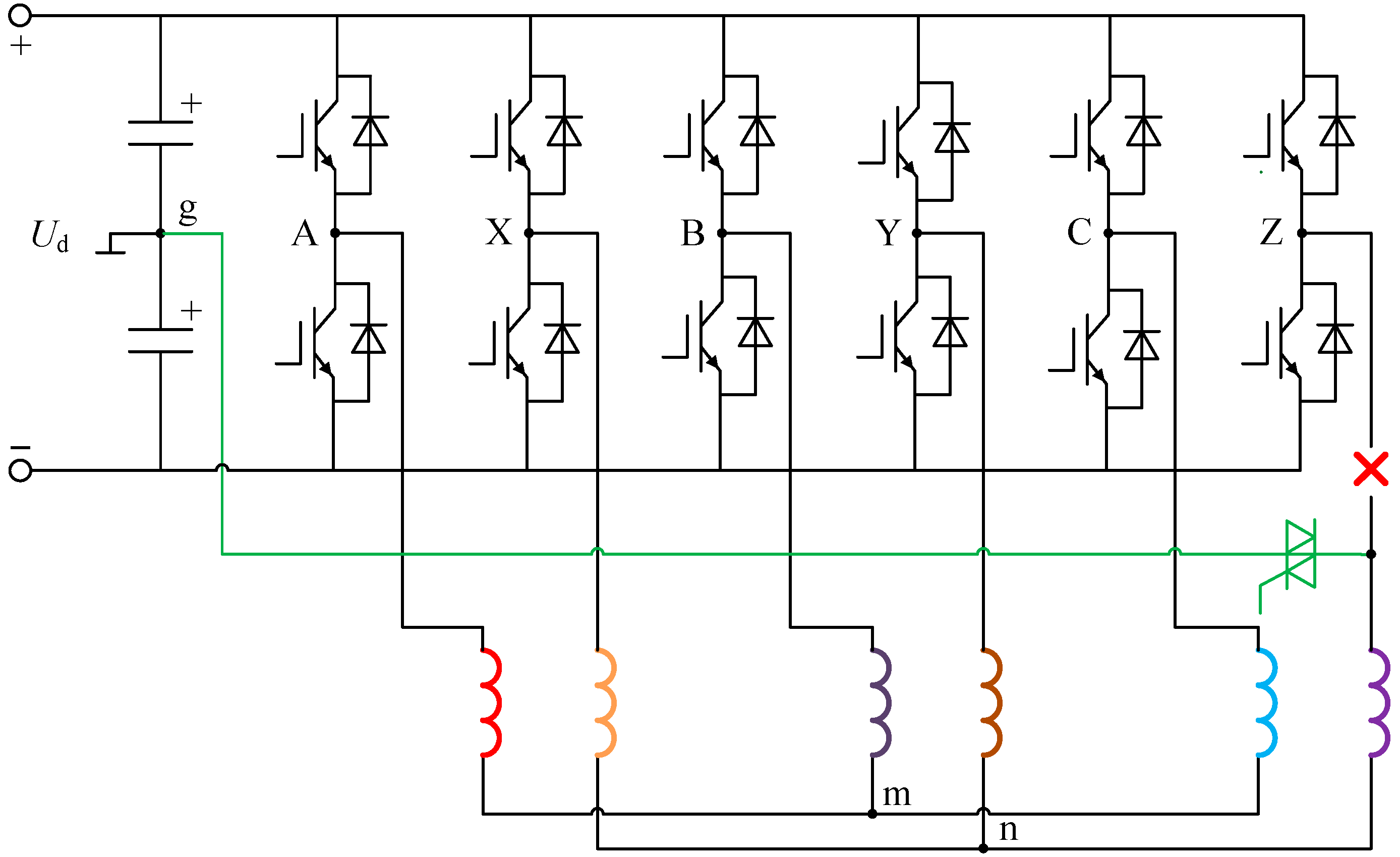
In this paper, a dual three-phase PMSM with two sets of star-connected windings with isolated neutral points is investigated. Assuming the single-leg open-circuit fault occurs in phase Z of the inverter, in order to continue utilizing the healthy phase-Z winding, the winding is connected to the inverter DC-link mid-point through a triode, as shown in Figure 1. When the fault is detected, the triode will be turned on.

Figure 1.
Post-fault circuit topology of windings and inverter.
The conventional fault-tolerant control only considers the symmetrical dual three-phase windings for the Ud/2 voltage level when modelling the motor to generate output torque. Although it can maintain the balanced six-phase currents, the torque-production capability is weakened.
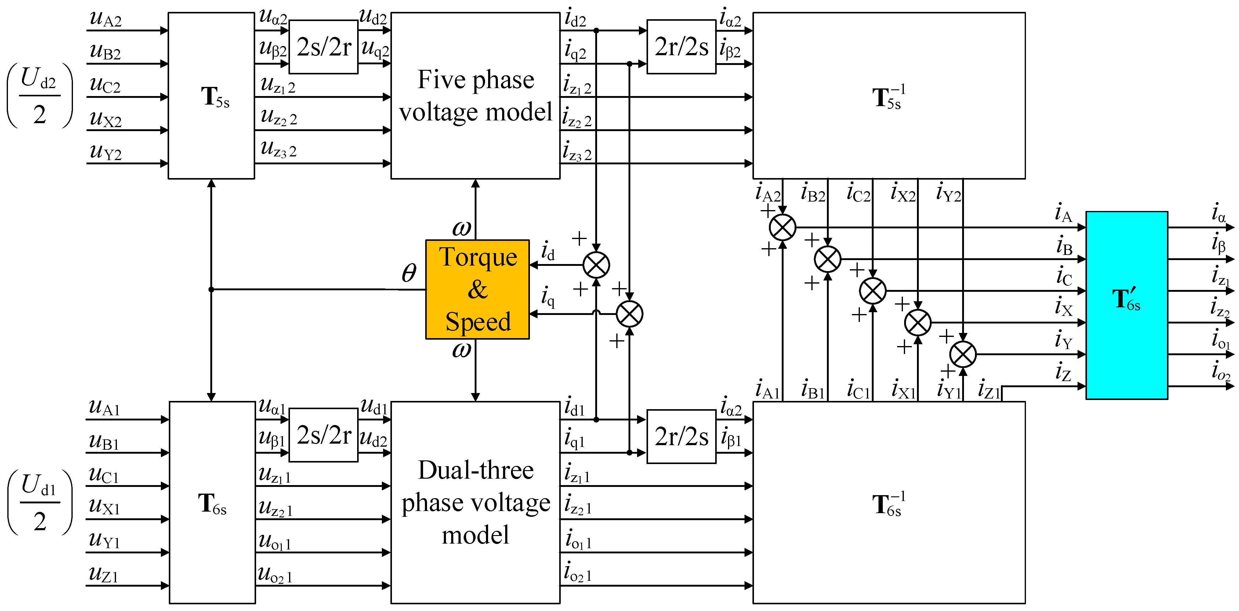
To improve the post-fault torque-production capability of the motor, when deriving the model, the asymmetric five-phase windings compensation torque model is superimposed on the basis of the symmetrical dual three-phase windings torque model for the same voltage level of Ud/2. Next, establish the mathematical model of the motor by vector space decomposition. The block diagram of the superposition control model of the post-fault dual three-phase PMSM is shown in Figure 2, where iA1 and iA2 are the phase-A current of the symmetric dual three-phase windings torque model and the asymmetric five-phase windings compensation torque model, respectively.
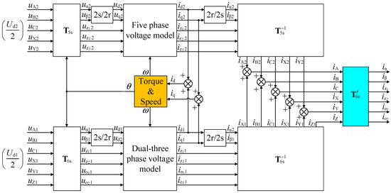
Figure 2.
The block diagram of the superposition control model of the post-fault dual three-phase PMSM.
To control the post-fault motor through the stator currents obtained in Figure 2, the transformation matrix T′6s based on vector space decomposition (VSD) is derived. The stator currents can be transformed into three mutually orthogonal subplanes through T′6s to realize the decoupling control of the post-fault motor. The transformation process is expressed as
Assuming that the electromagnetic torque from the symmetric dual three-phase windings torque model and the asymmetric five-phase windings compensation torque model are a times and b times of the total output torque, respectively, where a + b = 1. The three-subplane current decomposition stationary transformation matrix T′6s for the superposition control model is obtained as
According to the voltage and flux linkage equations of the motor, the voltage-space decoupling model of the fundamental wave for the symmetric dual three-phase windings torque model can be obtained as
where Laad and Laaq are the stator self-inductance of d-axis and q-axis, respectively; Rs and Laal are the stator resistance and leakage self-inductance, respectively; ψfd is the amplitude of the permanent magnet flux linkage in each phase winding; ω is the rotor electric angular velocity; M6p and N6p are the coefficient matrices of the symmetric dual three-phase windings torque model; M5p and N5p are the coefficient matrices of the asymmetric five-phase windings compensation torque model.
The coefficient matrices in Equation (3) can be obtained as
The harmonic voltage-space decoupling model of the post-fault motor can be obtained as
Because the expressions of the electromagnetic torque Te for the two torque models are the same, rotor speed ω, rotor electrical angle θ and electromagnetic torque Te of the whole motor can be derived by the sum of the d-q subplane currents of the two torque models correspondingly.
Finally, the phase currents of the two torque models can be obtained by the three-subplane decomposition stationary inverse transformation and the phase currents of the post-fault motor can be obtained by the sum of the phase currents of the two models correspondingly.
3. Proposed Fault-Tolerant Control Methods
3.1. Post-Fault Space Decomposition Stationary Transformation Matrix
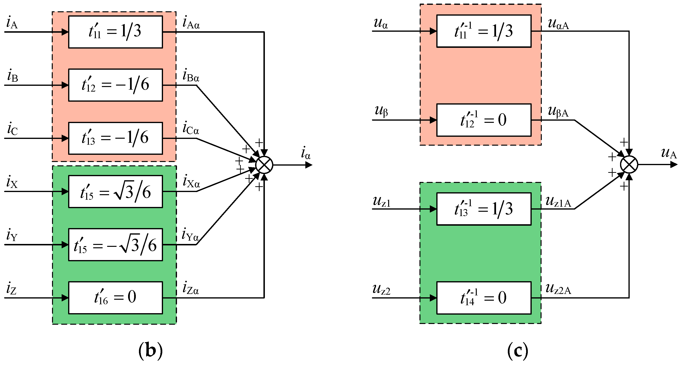
As the motor is not damaged when the fault occurs, the controller structure of the healthy dual three-phase PMSM can still be applied. However, it is necessary to reconstruct the space decomposition stationary transformation matrix T′6s. Taking the derivation of the elements in the first row of T′6s as an example, the deriving process is shown in Figure 3. In Figure 3a, iA1 and iA2 are the A-axis currents of the symmetric dual three-phase windings torque model and the asymmetric five-phase windings compensation torque model, respectively; iAa1 and iAa2 are the projection of the A-axis currents in the α-axis for the two torque models, respectively; tij_1 and tij_2 are the elements in the i-th row and the j-th column of T6s and T5s, respectively; iα is the α-axis current of the motor. It can be seen in Figure 3a that iα of the two torque models can be obtained from the first rows of T6s and T5s, respectively. However, in the actual situation, only the phase currents of the motor can be measured. These currents are superimposed by the phase currents of the two models. Therefore, it is necessary to derive the elements of the first row of T′6s of the motor through the first rows of T6s and T5s. In Figure 3b, t′ij is the element in the i-th row and the j-th column of T′6s. By calculating the appropriate element, the same iα as shown in Figure 3a can be obtained in Figure 3b, and the other axis currents can also be obtained by the corresponding coefficient. When all elements of T′6s have been calculated, the three-subplane decomposition inverse transformation matrix T′−16s can be obtained by inverting T′6s. It is shown in Figure 3c that the phase-A voltage is obtained by inverse three-subplane decomposition transformation, and the other phase voltage can also be obtained by the correspondence coefficients. Because the neutral points of both the motor windings are independent, uo1 and uo2 are 0. Therefore, these two voltage components do not participate in the calculation in the inverse three-subplane decomposition transformation.
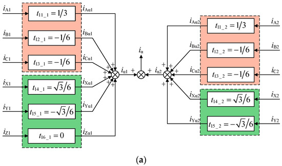
Figure 3.
The block diagram of the three-subplane decomposition stationary transformation (take the transformation to obtain iα and uA as an example). (a) The transformation by T6s and T5s. (b) Three-subplane decomposition transformation. (c) Three-subplane decomposition inverse transformation.
The specific process of deriving T’6s is shown as follows. First, obtain the first and second rows (α-β subplane) of T’6s according to the phase relationship between the windings. The fifth and sixth rows (o1-o2 subplane) of T’6s can be obtained according to the current constraint between the windings. As the relationship of the windings has not changed when the fault occurs, these two subplans of T’6s should be the same as the subplanes of matrix T6s correspondingly. After that, comparing the third row (z1 axis) of T6s and T5s, it can be found that the first five elements of the z1 axis of the two matrices are the same, and the sixth element of T6s is 0. It means that when the same phase voltage input, the voltage components transformed in the z1 axis of two torque model are also the same, so the z1 axis of T’6s can also be the same as the z1 axis of T6s. It is difficult to derive the fourth row (z2 axis) in T’6s directly from the objective of minimum copper losses. Besides, for the motor connected as shown in Figure 2, the current of phase Z should be half of the healthy current, and the motor torque depends on the sum of the RMS current values in each phase transformed to the d-q subplane. Therefore, to maximize the torque-production capability of the post-fault motor, the proposed fault-tolerance control makes the current of phase Z to half of the pre-fault current, which can fully utilize the fault phase winding.
Based on setting the given values of z1-z2 subplane in T’6s to 0 to achieve the minimum stator copper losses, z2 axis in T’6s can be derived by the constraint that the phase-Z current is half of the pre-fault current. The value of z2 axis in T’6s to meet the above conditions is not unique. T’6s obtained in this paper is expressed as
By pre-multiplying the given values of the currents of each subplane by the inverse of T’6s, the expression for the phase currents of the post-fault motor in steady state is obtained as
where Im is the phase current amplitude of the healthy motor, and θA is the phase angle of the phase-A current. When T’6s is applied to realize the control strategy, the phase current amplitudes are no longer equal, and the relationship of phase currents is no longer the same as that of phase windings. It is the inevitable result to ensure the post-fault magnetomotive force is the same as that of healthy motor.
The copper losses of the conventional control strategy of removing the faulty phase are up to 4.50I2mRs. In comparison, according to the current values of each phase shown in Equation (7), the copper losses of the post-fault motor under the TSC fault-tolerant control are only 3.43I2mRs (Table 1). It can be found that the TSC fault-tolerant control can effectively reduce the copper losses.

Table 1.
The RMS value of the phase current and the copper losses under different control methods.
3.2. Fault-Tolerant Decoupling Control in the d-q Subplane
The currents in the d-q subplane of the motor can be obtained by pre-multiplying the phase currents by T’6s and by rotational coordinate transformation. These currents are the sum of the currents in the d-q subplane of the symmetric dual three-phase windings torque model and the asymmetric five-phase windings compensation torque model, respectively. To construct the d-q subplane model of the motor, it is necessary to combine the d-q subplane models of the symmetric dual three-phase windings torque model and the asymmetric five-phase windings compensation torque model. However, the form of the combination is not unique and depends on the proportion of the output electromagnetic torque by the two models in that of the motor. The change of the combination form of the two models during motor operation increases the difficulty of the control system design. To solve these two problems, the decoupling control strategy is designed in this paper to reduce the degree of coupling in the d-q subplane as much as possible based on excluding the influence of the change of combination form.
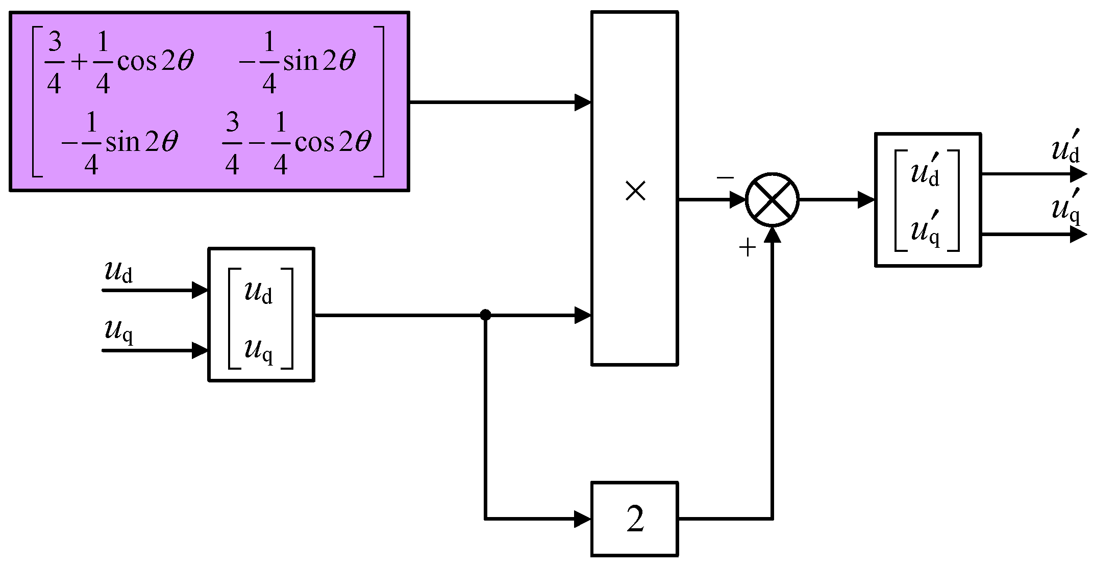
In order to decouple the d-q subplane model, both sides of Equation (3) are pre-multiplied by (2I-M−15p). Then, the new control variables u’d and u’q can be constructed as Equation (8), where I is the second order identity matrix and M−15p is the inverse of M5p in Equation (3).
where
The block diagram of the fault-tolerant decoupling model in the d-q subplane is shown in Figure 4.

Figure 4.
The block diagram of the fault-tolerant decoupling model in the d-q subplane.
It can be found that the coefficient matrixes in Equation (9) no longer contains the unknown quantities a and b, which means the Equation (8) does not change with the change of the combination form of these two torque models. Thus, the influence of the combination form on the control performance can be excluded. Meanwhile, the variables u’d and u’q are no longer coupled by the direct component, only the remaining alternating component leads to coupling, and there are coefficients less than 1 for each alternating component. Therefore, the influence of the alternating component on the control performance is small, which results in the degree of coupling of the d-q subplane voltages u’d and u’q is actually small.
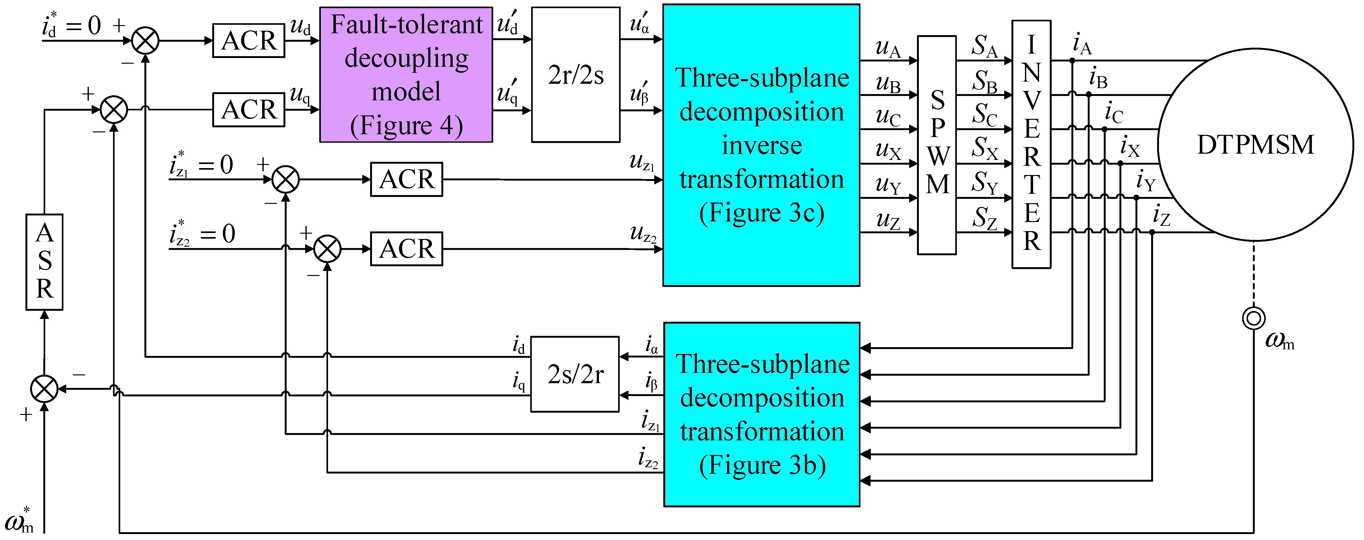
From the above strategies, the block diagram for TSC control of post-fault dual three-phase PMSM can be designed as shown in Figure 5, where SA is the switching signal of the inverter power device of phase A. It can be seen that the stator phase currents will be transformed to each subplane by the space decomposition transformation and 2s/2r transformation to realize the fault-tolerant control of the motor. Then the decoupling model of the d-q subplane is used to decouple the d-q subplane voltages. Finally, the switching signals is generated by SPWM to control the post-fault motor through inverter.
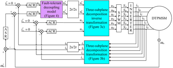
Figure 5.
The block diagram for TSC control of post-fault dual three-phase PMSM.
4. Simulation and Results Analysis
A simulation model is built to verify the effectiveness of the proposed TSC fault-tolerant control strategy. The parameters of the dual three-phase PMSM are shown in Table 2.
Table 2.
Parameters of the dual three-phase PMSM.
4.1. Torque Superposition Compensation Fault-Tolerant Control
For the control system, the DC-link voltage is 400 V, the sampling time is 2 μs. Field orientation control with i*d = 0 and SPWM is used, and the carrier frequency of PWM is 10 kHz. The given motor speed is 450 r/min and the given torque is 40 N·m.
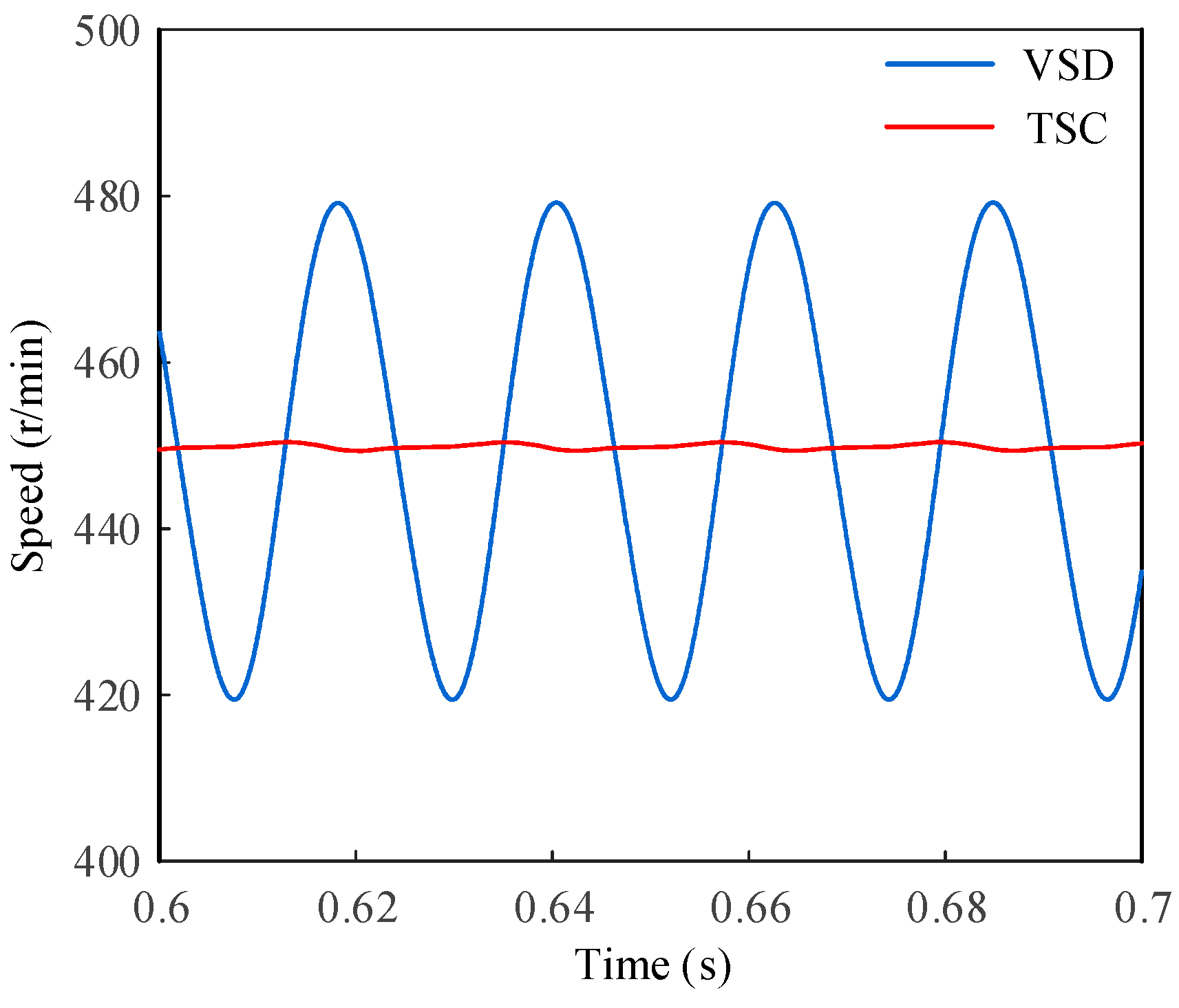
Figure 6 shows the speed waveforms of the motor with an inverter single-leg open-circuit fault for the non-fault-tolerant decoupling control and the TSC control, respectively. The motor speed is no longer able to track the given value stably and the speed ripple is up to 30 r/min of the non-fault-tolerant decoupling control. While the motor speed is still stable around the given value and the speed ripple is only 0.5 r/min of the TSC fault-tolerant control.

Figure 6.
Speed waveforms of the non-fault-tolerant decoupling control and the TSC fault-tolerant control.
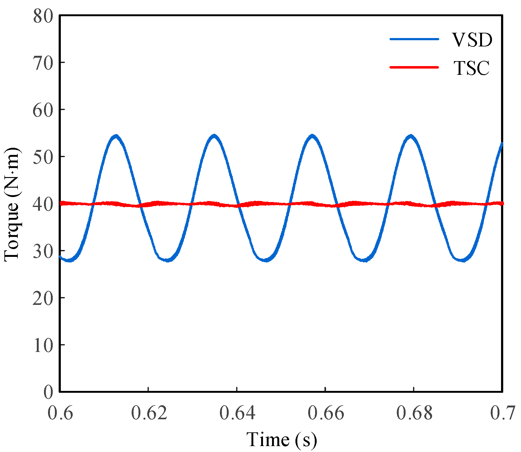
Figure 7 shows the torque waveforms of the faulty motor for the non-fault-tolerant decoupling control and the TSC fault-tolerant control, respectively. Like the speed waveforms, the motor torque fluctuates around the given value with a magnitude of 15 N·m of the non-fault-tolerant decoupling control, while for the TSC fault-tolerant control, the motor torque fluctuates by only 0.9 N·m.
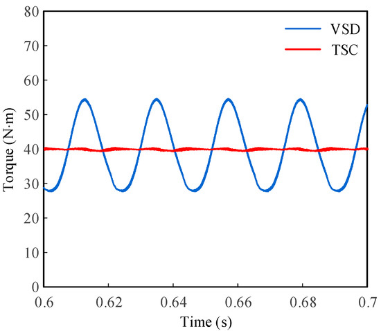
Figure 7.
Torque waveforms for the non-fault-tolerant decoupling control and the TSC fault-tolerant control.
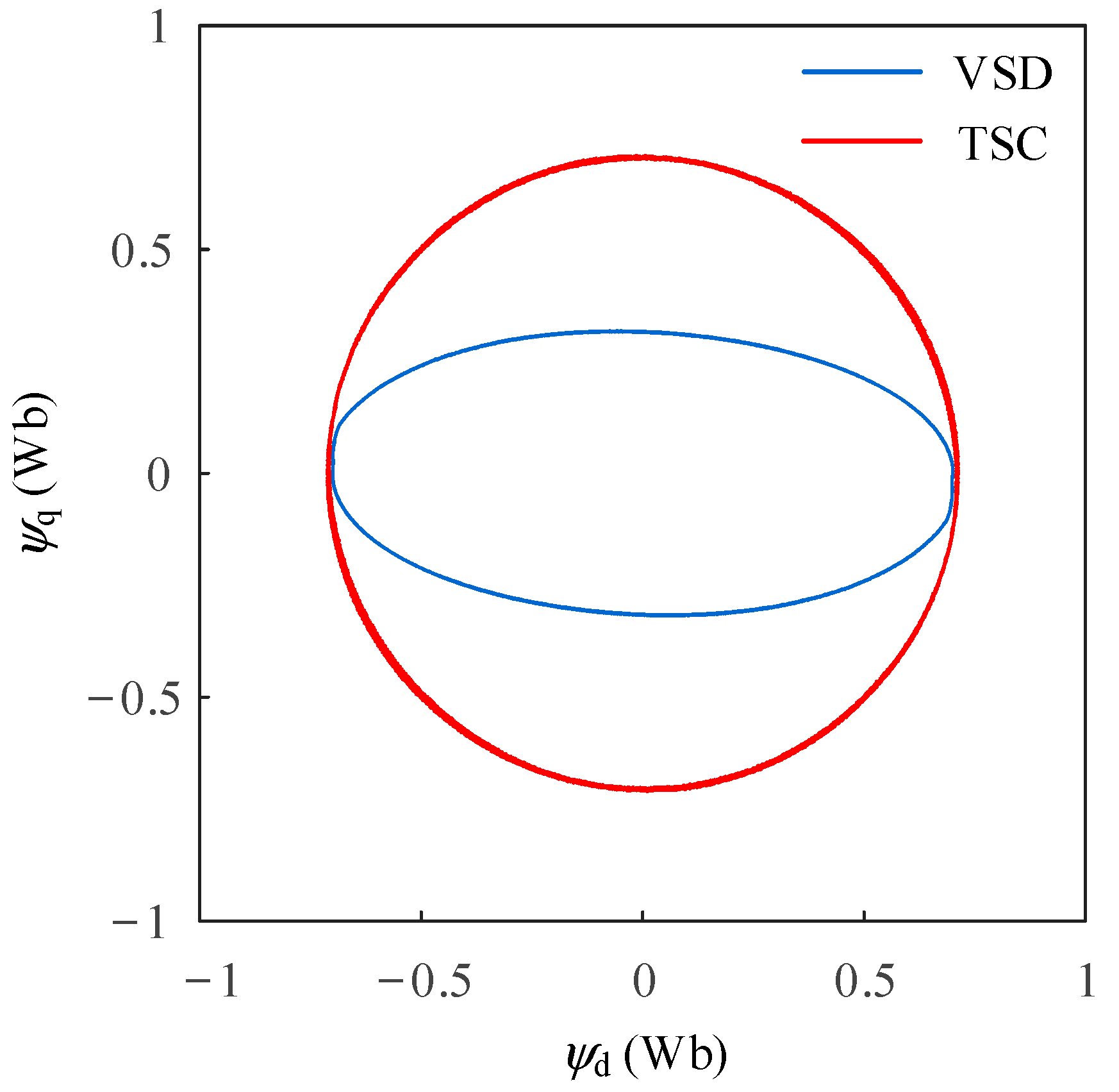
Figure 8 shows the flux linkage trajectory in the d-q subplane of the post-fault motor for the non-fault-tolerant decoupling control and the TSC fault-tolerant control, respectively. The flux linkage trajectory has become an ellipse of the non-fault-tolerant decoupling control, while for the TSC control, the flux linkage trajectory can maintain a circle.
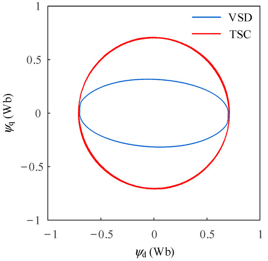
Figure 8.
Flux linkage trajectory in the d-q subplane for the non-fault-tolerant decoupling control and the TSC control.
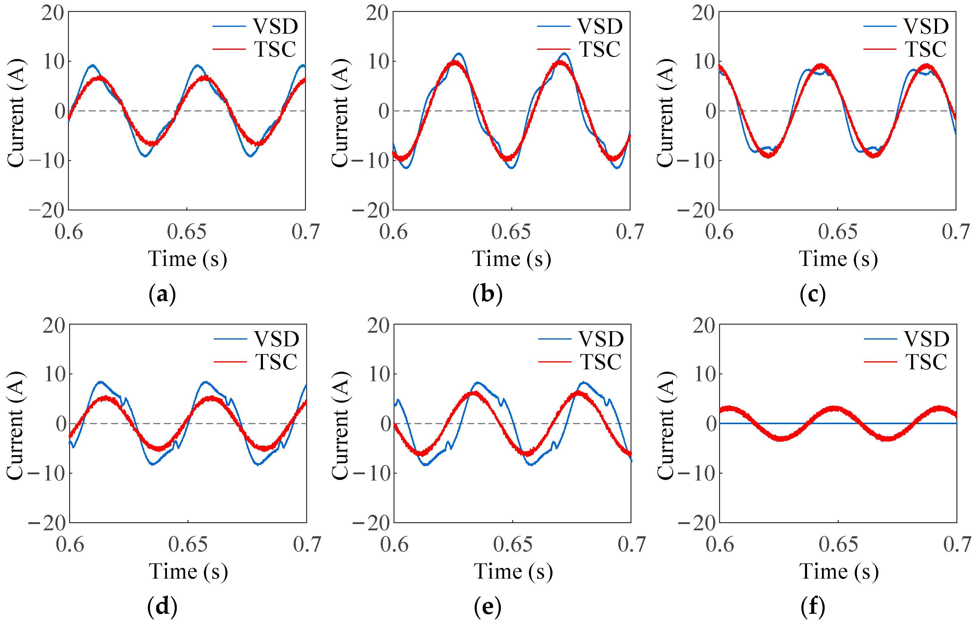
Figure 9 shows the phase currents of the post-fault motor for the non-fault-tolerant decoupling control and the TSC control, respectively. The phase-Z current is zero for the non-fault-tolerant decoupling control. The current RMS values of the other five phases have increased, and the waveforms have been distorted. While the phase currents can correspond to the expression in Equation (7), and all of them are sinusoidal of the TSC fault-tolerant control.
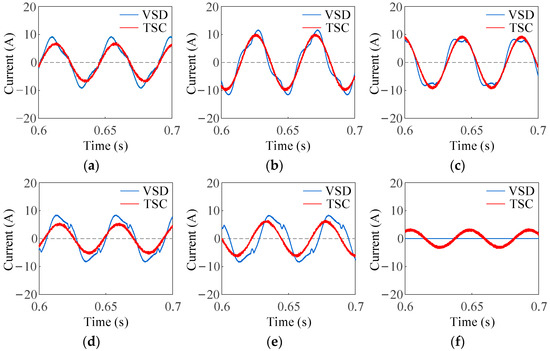
Figure 9.
Phase currents for the non-fault-tolerant decoupling control and the TSC fault-tolerant control. (a) Phase A. (b) Phase B. (c) Phase C. (d) Phase X. (e) Phase Y. (f) Phase Z.
It can be obtained from Figure 9 that the copper losses of the post-fault motor of the non-fault-tolerant decoupling control are up to 277.84 W, while the copper losses under the TSC control is only 207.77 W. The simulation results show that the copper losses for the TSC fault-tolerant control decreased by 25% compared with the non-fault-tolerant decoupling control.
4.2. Analysis of Speed and Torque Fluctuations of Fault-Tolerant Decoupling Control in the d-q Subplane
The given motor speed is 450 r/min and the given torque is 40 N·m. The conventional strategy of removing the faulty phase (denoted by strategy I), the conventional decoupling control strategy for the healthy motor (denoted by strategy II), and the proposed decoupling control strategy (denoted by strategy III) are applied to the post-fault motor, respectively. The motor speed and torque waveforms obtained are shown in Figure 10. The motor speed and torque in steady state of the three control strategies all fluctuate around the given value, but the fluctuation range is different. The fluctuation range of speed is 3 r/min, 1 r/min and 0.5 r/min, respectively, and the fluctuation range of torque is 2 N·m, 1.1 N·m and 0.9 N·m, respectively. It can be found that the speed and torque fluctuation of the motor of the proposed decoupling control strategy are smaller than those of the other two control strategies, and the speed and torque ripple of the proposed strategy decreased by 83% and 55% compared with the conventional decoupling control strategy, respectively.
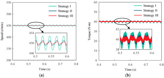
Figure 10.
Simulation results of the three decoupling control strategies for faulty dual three-phase PMSM. (a) Speed. (b) Torque.
4.3. Analysis of Torque-Production Capability
When the DC-link voltage is 400 V, if the motor speed is given as 450 r/min, the rated torque during healthy operation is 80 N·m.
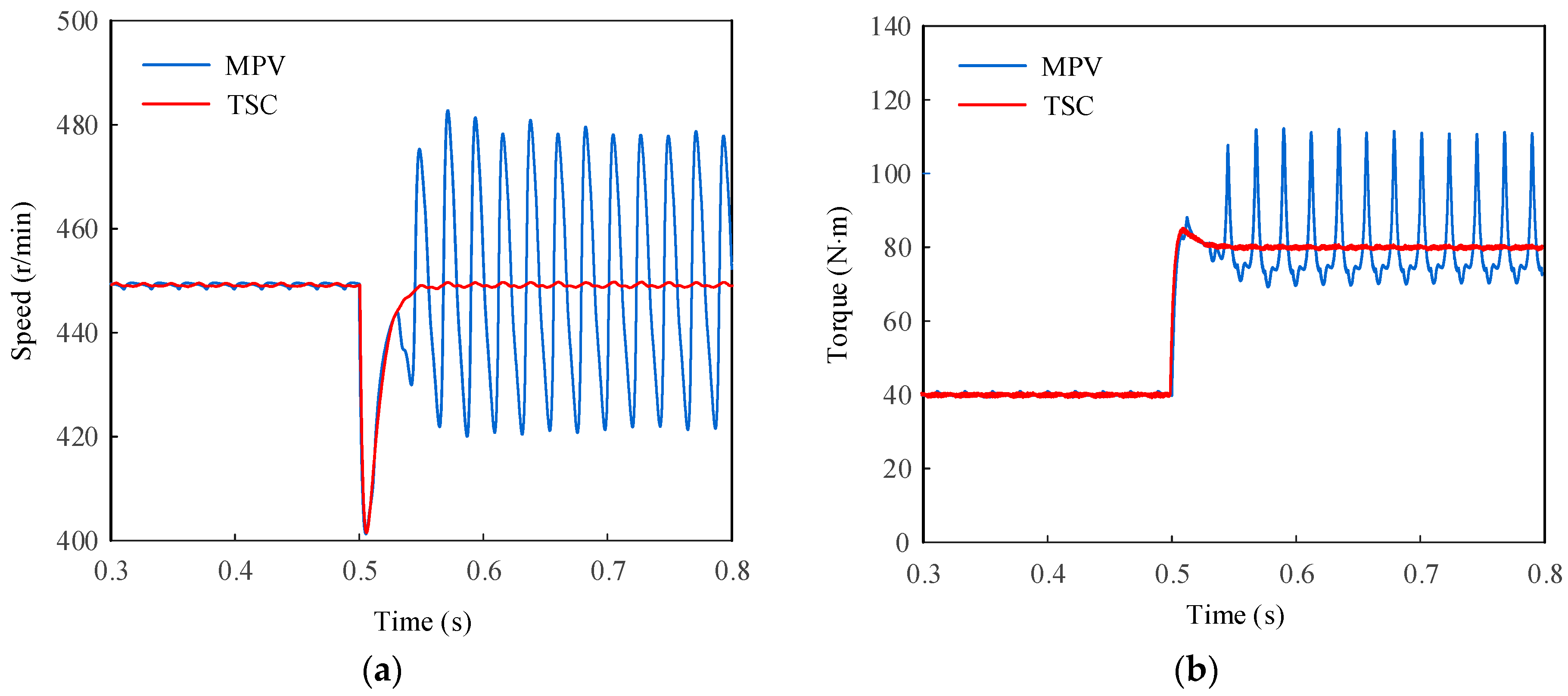
The motor is set to start at a load torque of 40 N·m, and the inverter single-leg open-circuit fault occurs at 0.1 s, the mid-point voltage (MPV) fault-tolerant control and the TSC fault-tolerant control are applied, respectively. Then, the load torque is increased to 80 N·m at 0.5 s and the motor speed and torque waveforms are obtained as shown in Figure 11. It can be seen that when the load torque is half of the rated motor torque, both the MPV control and the TSC control can control the motor stably. However, when the load torque rises to the rated torque, the torque-production capability of the MPV control is not enough to drive the load, resulting in large fluctuations in motor speed and torque, while for the TSC fault-tolerant control, the motor speed and torque can still track the given value stably.

Figure 11.
Improved load torque simulation results for the MPV and TSC control for faulty dual three-phase PMSM. (a) Speed. (b) Torque.
The motor is set to a given speed of 450 r/min and started at a load torque of 40 N·m. Then, the inverter single-leg open-circuit fault occurs at 0.1 s, the MPV control and TSC control are applied, respectively. To compare the speed-output capability of these two fault-tolerant controls, the given speed is increased to 650 r/min at 0.5 s. The motor speed and torque waveforms are obtained as shown in Figure 12. It can be found that when the given speed is slow, both fault-tolerant controls can control the motor stably. However, when the given speed is increased, the motor speed and torque fluctuate significantly for the MPV fault-tolerant control, in which the speed can no longer reach the given value, while for the TSC fault-tolerant control, the motor speed and torque can still track the given point stably.
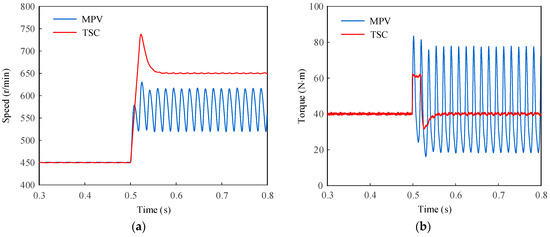
Figure 12.
Improved given speed simulation results for the MPV and TSC control for faulty dual three-phase PMSM. (a) Speed. (b) Torque.
5. Conclusions
In this paper, a TSC fault-tolerant control strategy achieving the torque superposition compensation for a dual three-phase PMSM with an inverter single-leg open-circuit fault is proposed. The phase winding originally connected to the faulty inverter leg is then linked to the DC-link mid-point when the fault occurs. The symmetric dual three-phase windings torque model and the asymmetric five-phase windings compensation torque model for Ud/2 voltage level are constructed according to the voltage level of each phase after fault, respectively. To achieve decoupled control of the two models, the space decomposition stationary transformation matrix is derived with the objective of increasing the torque-production capability and minimizing the stator copper losses. Then, to reduce the coupling of the d-q subplane obtained after the transformation, the decoupling control strategy in the d-q subplane is proposed. Simulation results show that the TSC control can significantly improve the torque-production capability of the post-fault motor compared with the traditional fault-tolerant decoupling control. Besides, the copper losses of TSC fault-tolerant control can be decreased by 25% compared with the non-fault-tolerant decoupling control. Additionally, the decoupling control strategy in the d-q subplane can make the speed ripple and torque ripple decrease by 83% and 55% compared with the conventional strategy of removing the faulty phase, respectively. The proposed control method has favourable prospects for application in fault-tolerant operation control systems of electric trucks, especially for the long-distance and heavy-load cases with open-circuit faults.
Author Contributions
Conceptualization, Y.Z. and F.Y.; methodology, F.Y. and S.Z.; software, Y.Z.; validation, Y.Z.; formal analysis, Y.Z., F.Y. and S.Z.; investigation, Y.Z. and F.Y.; resources, F.Y. and S.Z.; data curation, Y.Z. and F.Y.; writing—original draft preparation, Y.Z.; writing—review and editing, Y.Z. and F.Y.; visualization, Y.Z.; supervision, F.Y. and S.Z.; project administration, F.Y.; funding acquisition, F.Y. All authors have read and agreed to the published version of the manuscript.
Funding
This research was funded in part by the Natural Science Foundation of Shanghai under Grant 21ZR1402300, and in part by the Fundamental Research Funds for the Central Universities under Grant 2232019D3-53.
Conflicts of Interest
The authors declare no conflict of interest.
Nomenclature
| DTPMSM | Dual three-phase permanent-magnet synchronous motor. |
| TSC | Torque superposition compensation. |
| VSD | Vector space decomposition. |
| SPWM | Sinusoidal pulse width modulation. |
| ASR | Automatic speed regulator. |
| ACR | Automatic current regulator. |
| MPV | Mid-point voltage. |
| Ud | DC-link voltage. |
| Te | Electromagnetic torque. |
| ω | Rotor speed. |
| θ | Electrical angle. |
| Rs | Stator resistance. |
| Laad,aaq,aal | Stator self-inductance of d-axis and q-axis, leakage self-inductance. |
| Ψfd | Amplitude of permanent magnet flux linkage in each phase winding. |
| pn | Pole-pair number. |
References
- Qu, L.; Qiao, W.; Qu, L. An Enhanced Linear Active Disturbance Rejection Rotor Position Sensorless Control for Permanent Magnet Synchronous Motors. IEEE Trans. Power Electron. 2020, 35, 6175–6184. [Google Scholar] [CrossRef]
- Hu, W.; Ruan, C.; Nian, H.; Sun, D. Zero-Sequence Current Suppression Strategy with Common-Mode Voltage Control for Open-End Winding PMSM Drives with Common DC Bus. IEEE Trans. Ind. Electron. 2021, 68, 4691–4702. [Google Scholar] [CrossRef]
- Sharma, S.; Aware, M.V.; Bhowate, A. Symmetrical Six-Phase Induction Motor-Based Integrated Driveline of Electric Vehicle with Predictive Control. IEEE Trans. Transp. Electrif. 2020, 6, 635–646. [Google Scholar] [CrossRef]
- Salem, A.; Narimani, M. A Review on Multiphase Drives for Automotive Traction Applications. IEEE Trans. Transp. Electrif. 2019, 5, 1329–1348. [Google Scholar] [CrossRef]
- Tao, T.; Zhao, W.; Du, Y.; Cheng, Y.; Zhu, J. Simplified Fault-Tolerant Model Predictive Control for a Five-Phase Permanent-Magnet Motor with Reduced Computation Burden. IEEE Trans. Power Electron. 2020, 35, 3850–3858. [Google Scholar] [CrossRef]
- Zhou, X.; Sun, J.; Li, H.; Lu, M.; Zeng, F. PMSM Open-Phase Fault-Tolerant Control Strategy Based on Four-Leg Inverter. IEEE Trans. Power Electron. 2020, 35, 2799–2808. [Google Scholar] [CrossRef]
- Baneira, F.; Doval-Gandoy, J.; Yepes, A.G.; Lopez, O.; Pérez-Estévez, D. Control Strategy for Multiphase Drives with Minimum Losses in the Full Torque Operation Range Under Single Open-Phase Fault. IEEE Trans. Power Electron. 2017, 32, 6275–6285. [Google Scholar] [CrossRef]
- Munim, W.N.W.A.; Duran, M.J.; Che, H.S.; Bermúdez, M.; González-Prieto, I.; Rahim, N.A. A Unified Analysis of the Fault Tolerance Capability in Six-Phase Induction Motor Drives. IEEE Trans. Power Electron. 2017, 32, 7824–7836. [Google Scholar] [CrossRef]
- Wang, W.; Zhang, J.; Cheng, M. Common Model Predictive Control for Permanent-Magnet Synchronous Machine Drives Considering Single-Phase Open-Circuit Fault. IEEE Trans. Power Electron. 2017, 32, 5862–5872. [Google Scholar] [CrossRef]
- Wang, X.; Wang, Z.; Xu, Z.; Cheng, M.; Wang, W.; Hu, Y. Comprehensive Diagnosis and Tolerance Strategies for Electrical Faults and Sensor Faults in Dual Three-Phase PMSM Drives. IEEE Trans. Power Electron. 2019, 34, 6669–6684. [Google Scholar] [CrossRef]
- Tousizadeh, M.; Che, H.S.; Selvaraj, J.; Rahim, N.A.; Ooi, B.T. Performance Comparison of Fault-Tolerant Three-Phase Induction Motor Drives Considering Current and Voltage Limits. IEEE Trans. Ind. Electron. 2019, 66, 2639–2648. [Google Scholar] [CrossRef]
- Che, H.S.; Duran, M.J.; Levi, E.; Jones, M.; Hew, W.; Rahim, N.A. Postfault Operation of an Asymmetrical Six-Phase Induction Machine with Single and Two Isolated Neutral Points. IEEE Trans. Power Electron. 2014, 29, 5406–5416. [Google Scholar] [CrossRef] [Green Version]
- Melo, V.F.M.B.; Jacobina, C.B.; Rocha, N.; Braga-Filho, E.R. Fault Tolerance Performance of Two Hybrid Six-Phase Drive Systems Under Single-Phase Open-Circuit Fault Operation. IEEE Trans. Ind. Appl. 2019, 55, 2973–2983. [Google Scholar] [CrossRef]
- Guo, Y.; Wu, L.; Huang, X.; Fang, Y.; Liu, J. Adaptive Torque Ripple Suppression Methods of Three-Phase PMSM During Single-Phase Open-Circuit Fault-Tolerant Operation. IEEE Trans. Ind. Appl. 2020, 56, 4955–4965. [Google Scholar] [CrossRef]
- Zuo, Y.; Zhu, X.; Si, X.; Lee, C.H.T. Fault-Tolerant Control for Multiple Open-Leg Faults in Open-End Winding Permanent Magnet Synchronous Motor System Based on Winding Reconnection. IEEE Trans. Power Electron. 2021, 36, 6068–6078. [Google Scholar] [CrossRef]
- Hu, Y.; Huang, S.; Wu, X.; Li, X. Control of Dual Three-Phase Permanent Magnet Synchronous Machine Based on Five-Leg Inverter. IEEE Trans. Power Electron. 2019, 34, 11071–11079. [Google Scholar] [CrossRef]
- Zhang, X.; Xu, C. Second-Time Fault-Tolerant Topology and Control Strategy for the Open-Winding PMSM System Based on Shared Bridge Arm. IEEE Trans. Power Electron. 2020, 35, 12181–12193. [Google Scholar] [CrossRef]
- Jlassi, I.; Cardoso, A.J.M. Fault-Tolerant Back-to-Back Converter for Direct-Drive PMSG Wind Turbines Using Direct Torque and Power Control Techniques. IEEE Trans. Power Electron. 2019, 34, 11215–11227. [Google Scholar] [CrossRef]
- Zheng, J.; Huang, S.; Rong, F.; Lye, M. Six-Phase Space Vector PWM under Stator One-Phase Open-Circuit Fault Condition. Energies 2018, 11, 1796. [Google Scholar] [CrossRef] [Green Version]
- Yang, T.; Kawaguchi, T.; Hashimoto, S.; Jiang, W. Switching Sequence Model Predictive Direct Torque Control of IPMSMs for EVs in Switch Open-Circuit Fault-Tolerant Mode. Energies 2020, 13, 5593. [Google Scholar] [CrossRef]


Publisher’s Note: MDPI stays neutral with regard to jurisdictional claims in published maps and institutional affiliations. |
© 2022 by the authors. Licensee MDPI, Basel, Switzerland. This article is an open access article distributed under the terms and conditions of the Creative Commons Attribution (CC BY) license (https://creativecommons.org/licenses/by/4.0/).