Review

Optimization of the Load Capacity System of Powered Roof Support: A Review

by
Dawid Szurgacz
1,2,
Beata Borska
3,
Sergey Zhironkin
4,5,*,
Ryszard Diederichs
1 and
Anthony J. S. Spearing
6
1
Center of Hydraulics DOH Ltd., ul., Konstytucji 147, 41-906 Bytom, Poland
2
Polska Grupa Górnicza S.A., ul., Powstańców 30, 40-039 Katowice, Poland
3
KWK Ruda Ruch Halemba, ul., Halembska 160, 41-717 Ruda Sląska, Poland
4
Department of Trade and Marketing, Siberian Federal University, 79 Svobodny av., 660041 Krasnoyarsk, Russia
5
Department of Open Pit Mining, T.F. Gorbachev Kuzbass State Technical University, 28 Vesennya st., 650000 Kemerovo, Russia
6
School of Mines, China University of Mining and Technology, 1 Daxue Road, Tongshan District, Xuzhou 221116, China
*
Author to whom correspondence should be addressed.
Energies 2022, 15(16), 6061; https://doi.org/10.3390/en15166061
Submission received: 28 July 2022 / Revised: 17 August 2022 / Accepted: 18 August 2022 / Published: 21 August 2022

Abstract

:
Powered roof support is equipped with a hydraulic control system to ensure its required load capacity. The main problem arising from powered roof support during exploitation is providing the necessary load capacity. A decrease in load capacity is mainly associated with internal and external leakage in the cylinders, mainly in the hydraulic props. The hydraulic prop’s role is to ensure stability for the powered roof support. A special double block with an additional pressure boost was developed to counter the props’ leakage phenomenon. Pressure loss is replenished based on the solution proposed here. For this purpose, bench tests were commenced, in which a prop with an internal leakage was used. The research included the analysis of the operation of a boosted double block. The results allowed us to assess whether the developed solution can be the subject of further research conducted in real conditions.

1. Introduction

Global economic development [1,2] is increasing the demand for mineral resources [3,4,5,6]. The analysis of the literature indicates the following directions of development: increasing efficiency and intensification of production [7], improving the diagnostics of machines and devices [8,9,10,11], reducing the energy intensity of machines [12,13,14], improving safety [15,16,17,18] and effectively combating natural hazards [19,20]. Technological improvement takes into account the principles of sustainable development, which focus on environmental issues [21]. These include the idea of optimizing energy consumption [22,23], increasing the strength and reliability of machines [24,25,26,27] and optimizing the use of equipment [28,29]. The basis of modern development is conducting in situ research [30,31] and numerical analyses [32,33,34,35] using modern computer software [36,37,38,39], based on mathematical analyses [40,41,42,43,44,45,46,47,48].
Hard coal is one of the most important raw materials in the world economy [49,50]. It provides energy security for many countries. The global coal industry is driven by the need to improve efficiency [51,52,53] and intensify extraction [54], as well as increase safety [55,56,57,58]. This is a challenge and an incentive to look for new solutions [59,60,61] and technologies [62,63]. In addition, deteriorating mining and geological conditions place new requirements on the machines and equipment used [64,65,66].
The extraction of hard coal is carried out using the open pit and underground methods. The presented publication refers to the underground extraction of hard coal, in which a system of a mechanized wall complex is used (Figure 1). The wall complexes include a mining machine (in Polish mines, most often a combine harvester, less often a stream), a scraper conveyor and powered roof support. The purpose of the powered roof support is to properly direct the excavation roof and ensure the safety of miners and machines working in the longwall. In addition, the powered roof support is responsible for moving the entire wall complex with the progress of the longwall face. It also supports other machines of the complex [67,68].
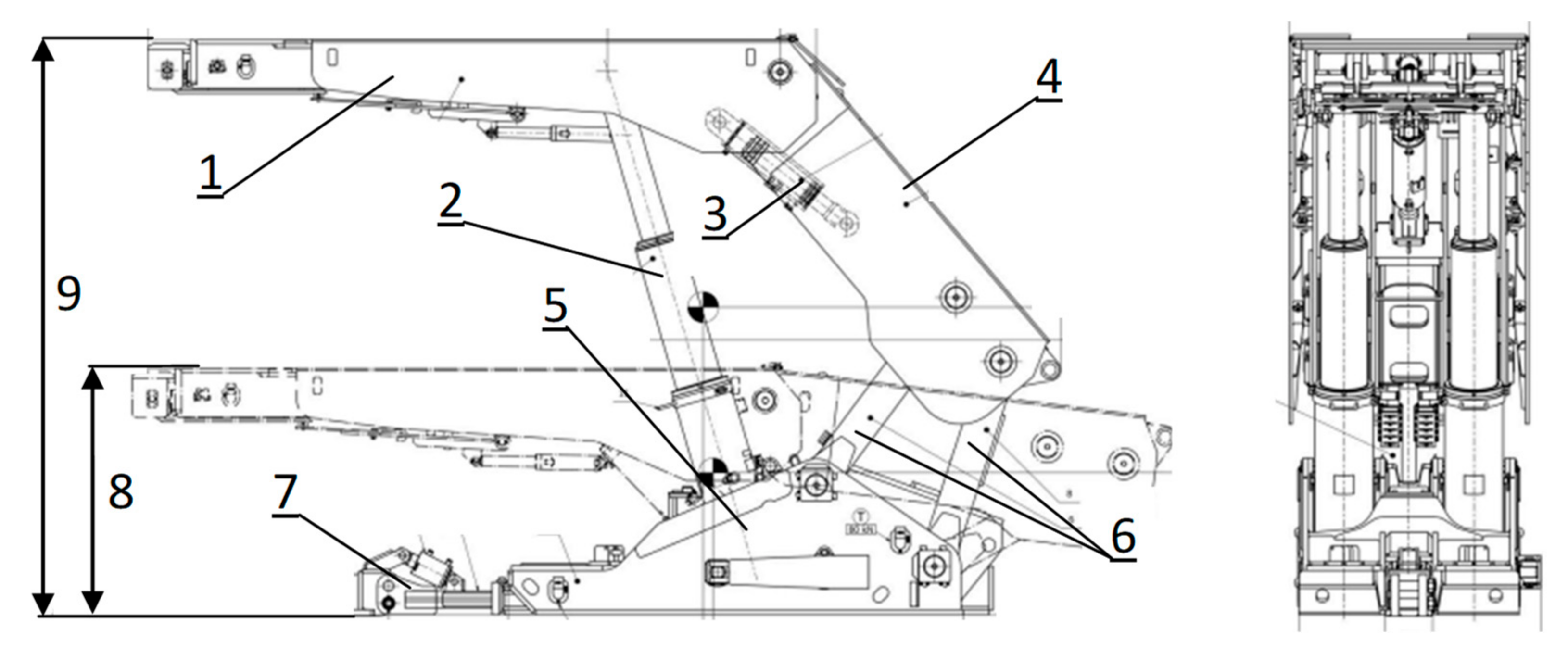
The powered roof support (Figure 2) consists of the structural part and the hydraulic system. The main elements in the powered roof support structure are the roof beam, the bottom sprang, the shield support and the lemniscate links [69]. The most important element of the hydraulic system is hydraulic props. These actuators are placed between the roof beam and the bottom sprang. They are largely responsible for obtaining the required support by the sections, i.e., the force with which the powered roof support acts on the roof. Maintaining adequate load capacity is essential for proper support of the roof and the safe operation of the longwall [70,71,72].
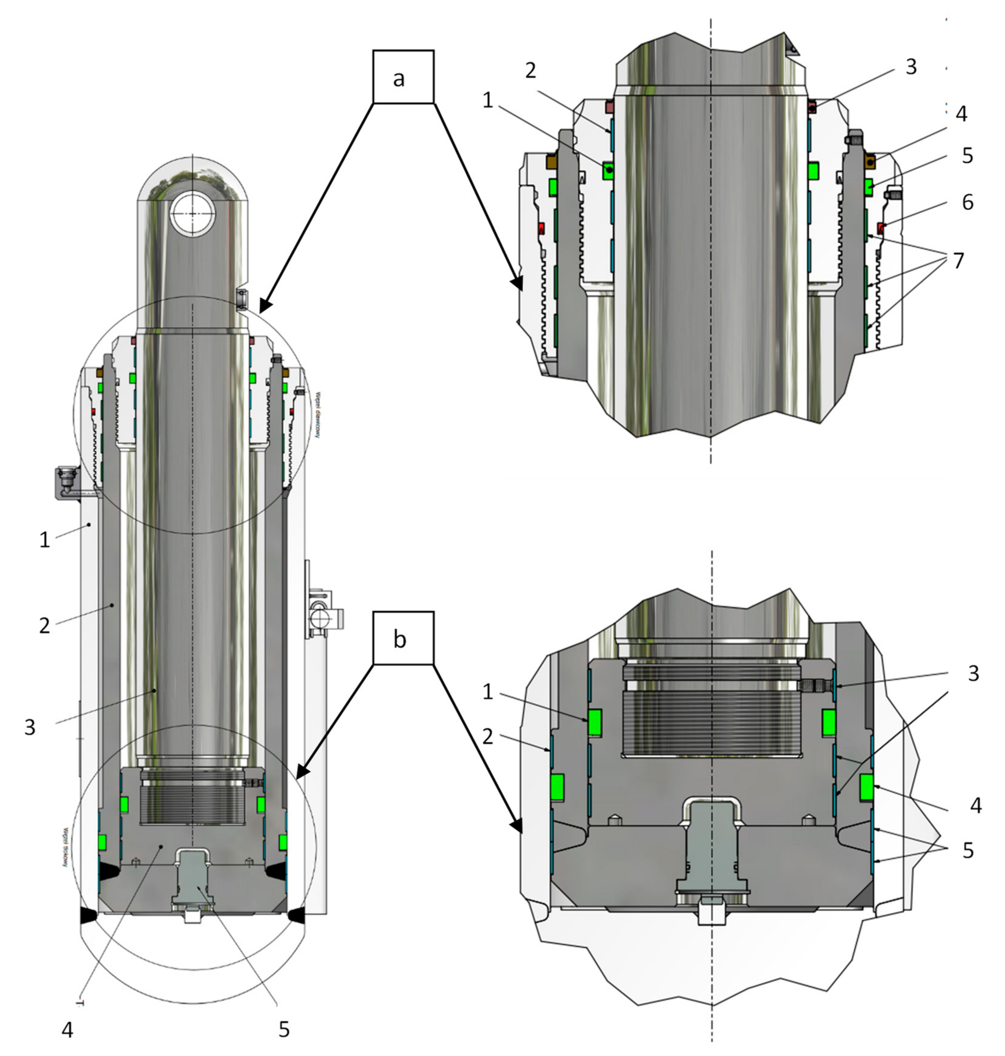
One of the main causes of loss of working load capacity is leakage in the hydraulic system of the prop and the structure of the hydraulics elements. For the powered roof support, the resulting leakage is divided into internal and external. The former arises from damage to the seals protecting the structure; it is invisible and thus difficult to diagnose. On the other hand, the latter (external leakage) concerns seals protecting the actuators against leakage of liquid pressure. Figure 3 shows the use of seals protecting the operation of the force elements and the hydraulic system.
Based on observations carried out thanks to monitoring measurement, it was possible to obtain an analysis of the development of leaks influenced by the impact of maintaining working load capacity. The monitoring included 160 s of the longwall. The sensors were located in the props and the actuator of the roof beam. The analysis covered about six months of exploitation. The wall was about 3.5 m high, 240 m long, and had a coasting area of about 850 m. Figure 4 shows the development of leaks for the selected section. It can be noticed in the initial phase of the graph that the prop showed technical efficiency. On the other hand, the following period of operation shows a reduction in its technical efficiency caused by the development of the leakage.
This article presents bench tests of the double block prototype with a recharging function. The research was aimed at determining the suitability of the prototype solution. In this respect, a special station was prepared, in which a prop with a block was placed. To obtain the test results, a special portable measuring system was used. The obtained research results determined the usefulness and correctness of the proposed solution. The conducted research allowed us to assess the proposed solution positively.

2. Materials and Methods

The operation of the powered roof support is determined based on three parameters: initial load capacity, working load capacity and nominal load capacity. Initial load capacity is obtained at the moment of section expansion. Its value depends on the instantaneous supply pressure in the longwall’s main supply line. After taking over the pressure of the roof rocks, the section obtains working load capacity. The value of the working load capacity is between the initial load capacity and the nominal load capacity. The section obtains nominal load capacity when the safety valves are opened. This is the maximum value of the load capacity that the section can achieve and depends on the settings of these valves [72]. The following formula can describe the working support:
F w = π d 2 4 p w
where
  • FW—working load capacity (N);
  • d—the prop’s diameter (mm);
  • Pw—pressure in the under-piston space of the prop (MPa).
To optimize the support system, the working load capacity in terms of its loss was analyzed based on temporary pressure drops, which were recorded by the formula
F R = π d 2 4 ( p w   Δ p ) ,   N
where
  • FR—actual load capacity (N);
  • d—the prop’s diameter (mm);
  • Pw—the pressure in the under-piston space of the prop (MPa);
  • ∑∆p—the sum of pressure losses in the under-piston space of the prop (MPa).
Pressure losses are mainly caused by internal and external leaks. These losses result in the loss of the required working load capacity, which significantly reduces the parameters of the powered roof support.

2.1. Double Valve Block

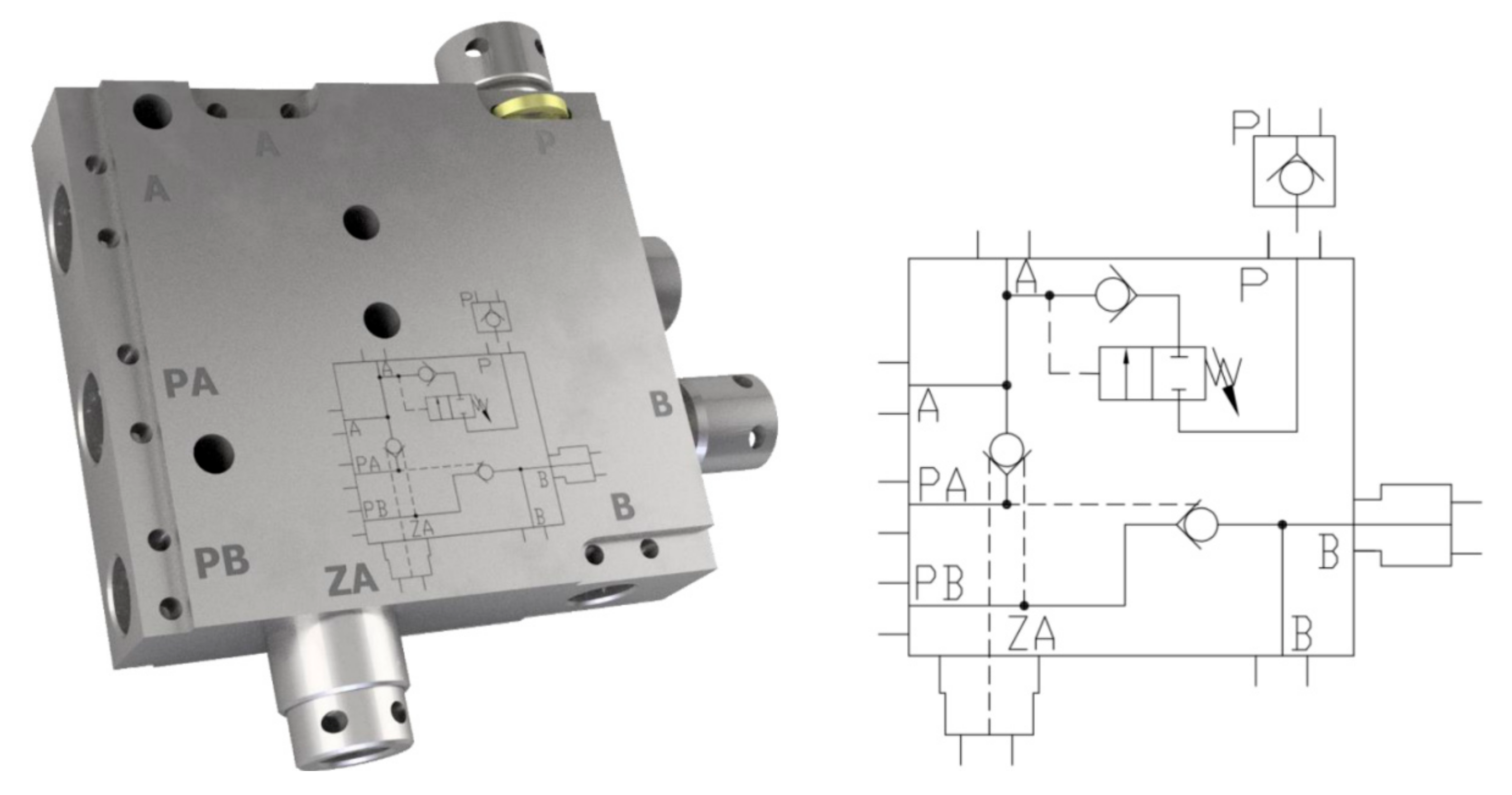
To minimize the effects affecting the reduction of the support, a change in the hydraulic system of the prop of the powered roof support was proposed. This change consists of using a double block with a recharging function. The double valve block is designed to expand the prop to the initial load capacity automatically. This is achieved thanks to the installation in the valve block of the threshold valve and ensures the automatic expansion of the prop from the pressure value of 9 MPa to the maximum pressure value in the main supply line.
In this respect, a prototype solution was developed, presented in Figure 5, and its parameters were considered in Table 1.

2.2. Bench Tests

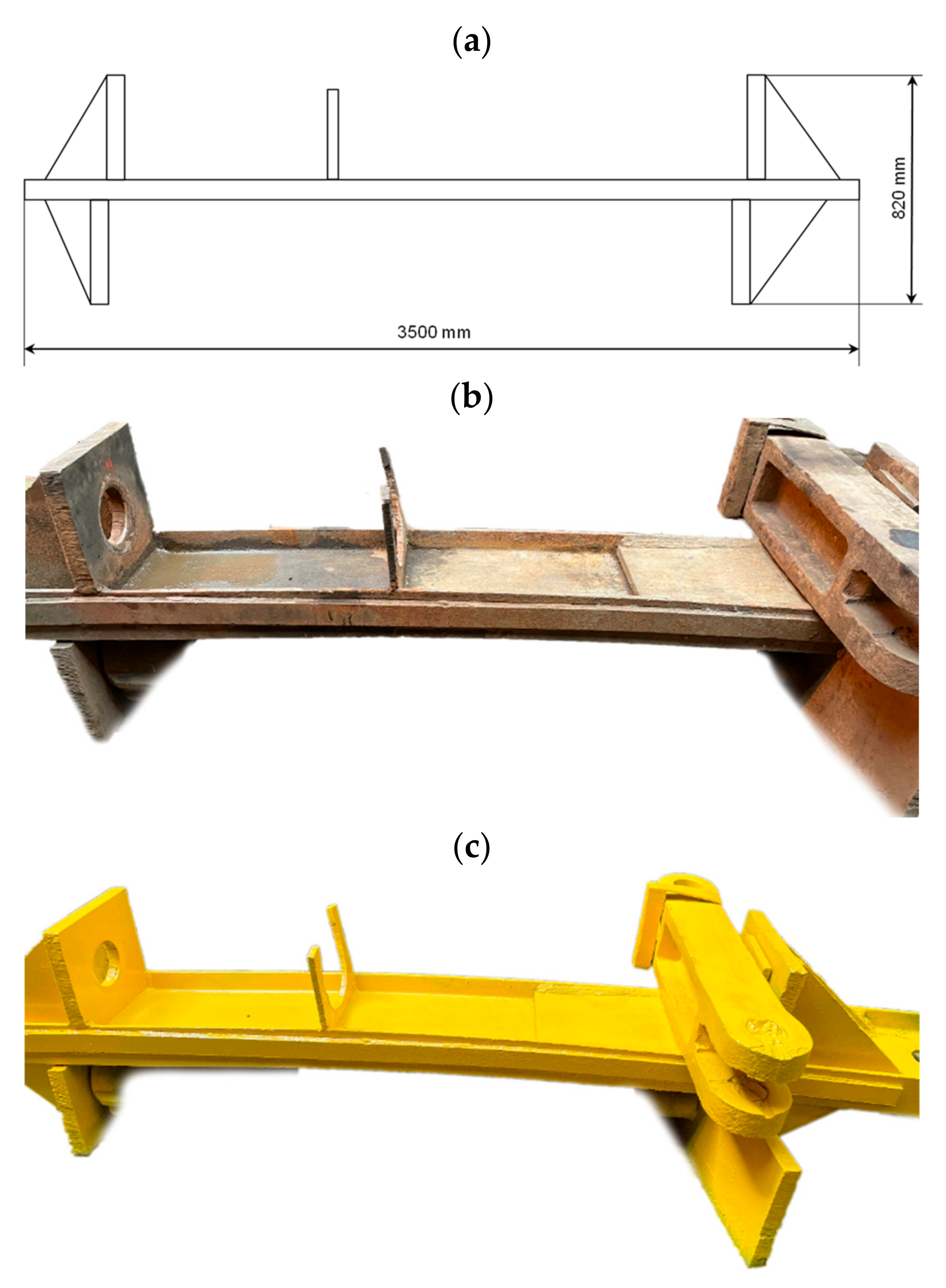
The bench tests of the proposed solution were carried out in the DOH laboratory using a hydraulic prop Ø 210 × 160. Its technical characteristics are presented in Table 2. A special stand was prepared for these tests, characterized by a frame with a length of 3500 mm and a height of 820 mm, as shown in Figure 6. The tested solution and the prop were expanded in the prop’s frame. Expanding and stripping the prop took place by supplying hydraulic fluid from the pump station.

2.3. Measuring System

A portable, multifunctional measuring device, The Parker Service Master Plus, was used to measure and record selected physical parameters necessary to assess the operation and suitability of the system. This device allows the measurement, monitoring and analysis of the following parameters: pressure, temperature, volume flow and speed. The device consists of 2 CAN main line networks and eight analogue sensors each. The measurements are carried out with a sampling frequency of 1 ms. In addition, the device has two fast inputs to digital sensors, for which the sampling frequency is 0.1 ms. The measurement of the selected parameter and its maximum and minimum value is displayed on the device screen in real-time. The measured values are stored in the built-in memory or on a micro SD card or USB device.
In the tests, which are the subject of this work, pressure measurements were made during the operation of the prototype block (Figure 7). Digital pressure sensors were used in the measurements. The sampling time was 0.1 ms (10,000 measurements/second). The measured values were recorded in the form of graphs of pressure changes over time.

3. Results

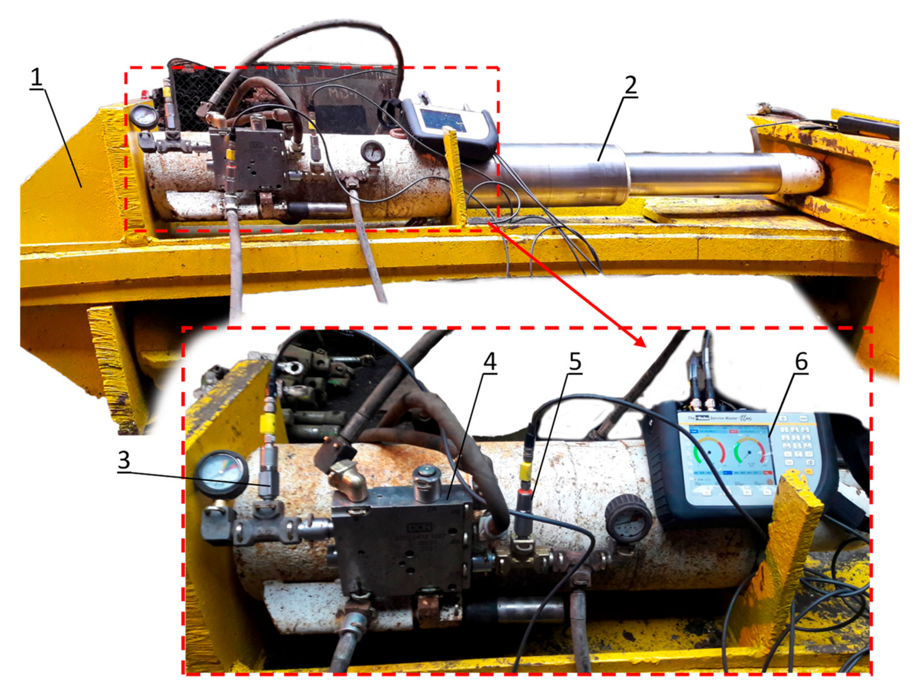
The conducted bench tests allowed us to obtain a measurement for the operation of a double block with a recharging function. The first measurements were focused on obtaining pressure in the sub-block and supra-block space. The supply pressure of 250 bar from the hydraulic pump station was assumed as the input parameter. Figure 8 shows a test site with the tested double block.
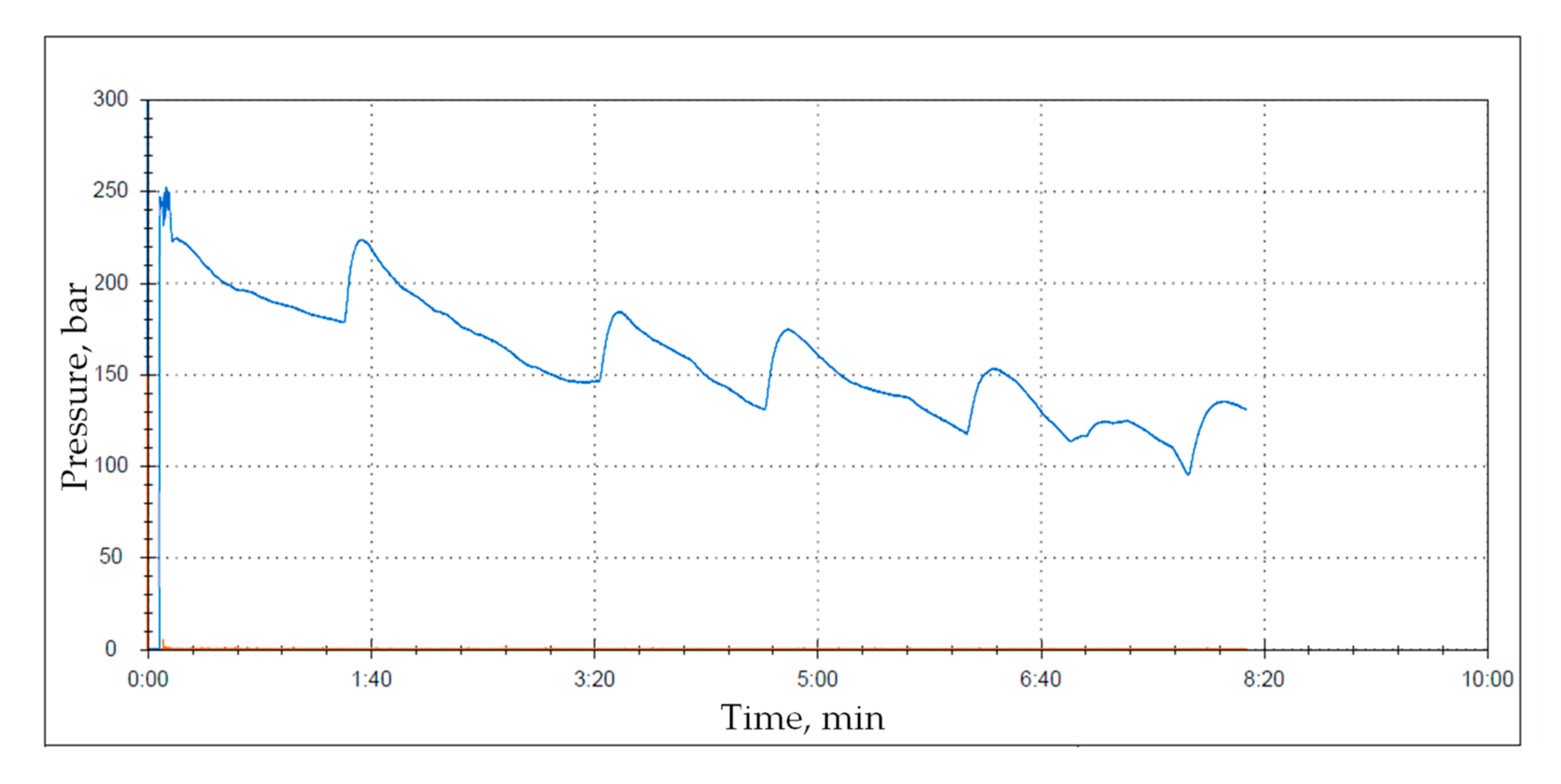
Figure 9 shows the test result illustrating the pressure course for the sub-block space of the prop with an internal leakage. The test lasted about 5 min, for which the optimal intensity of operation was obtained after 2 min of measurements.
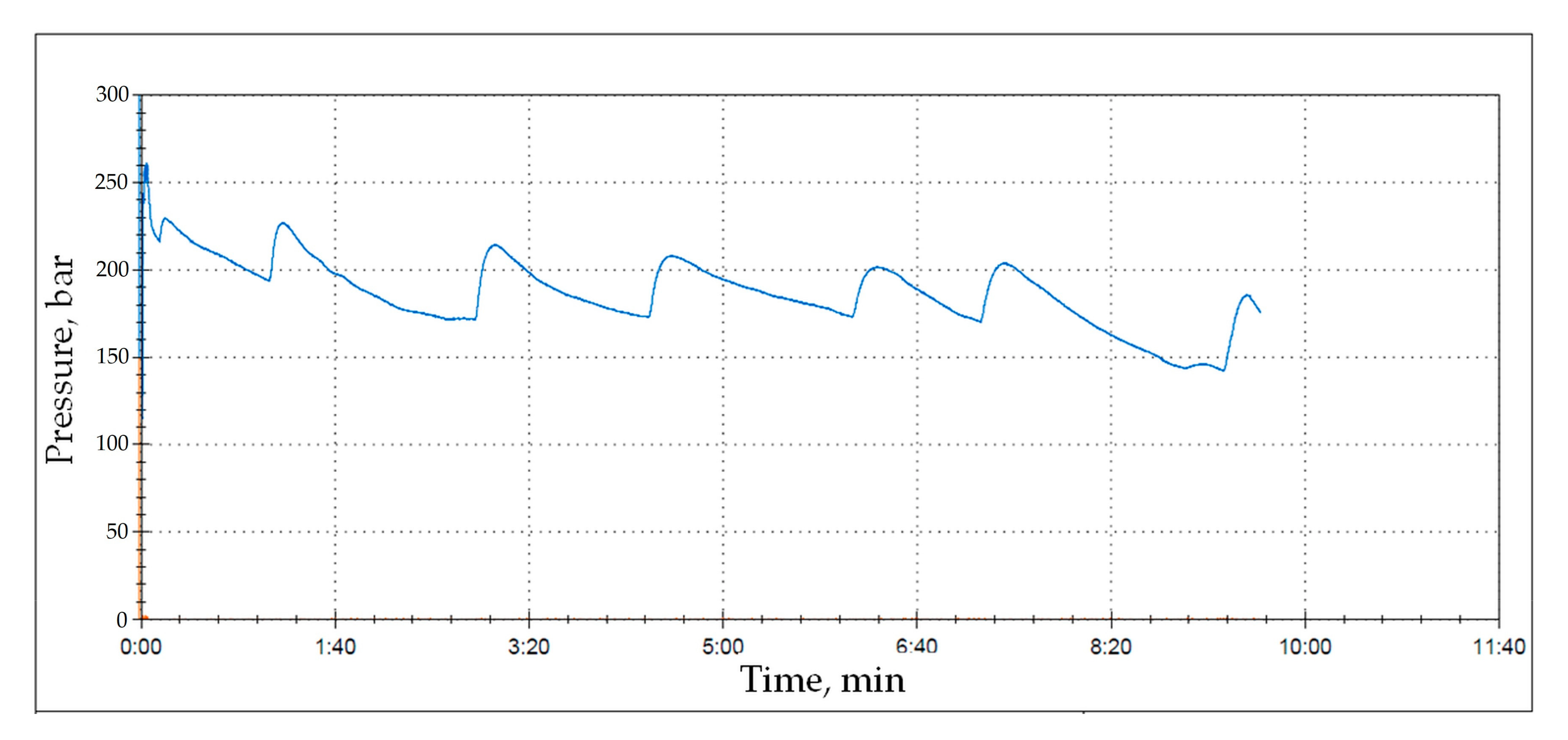
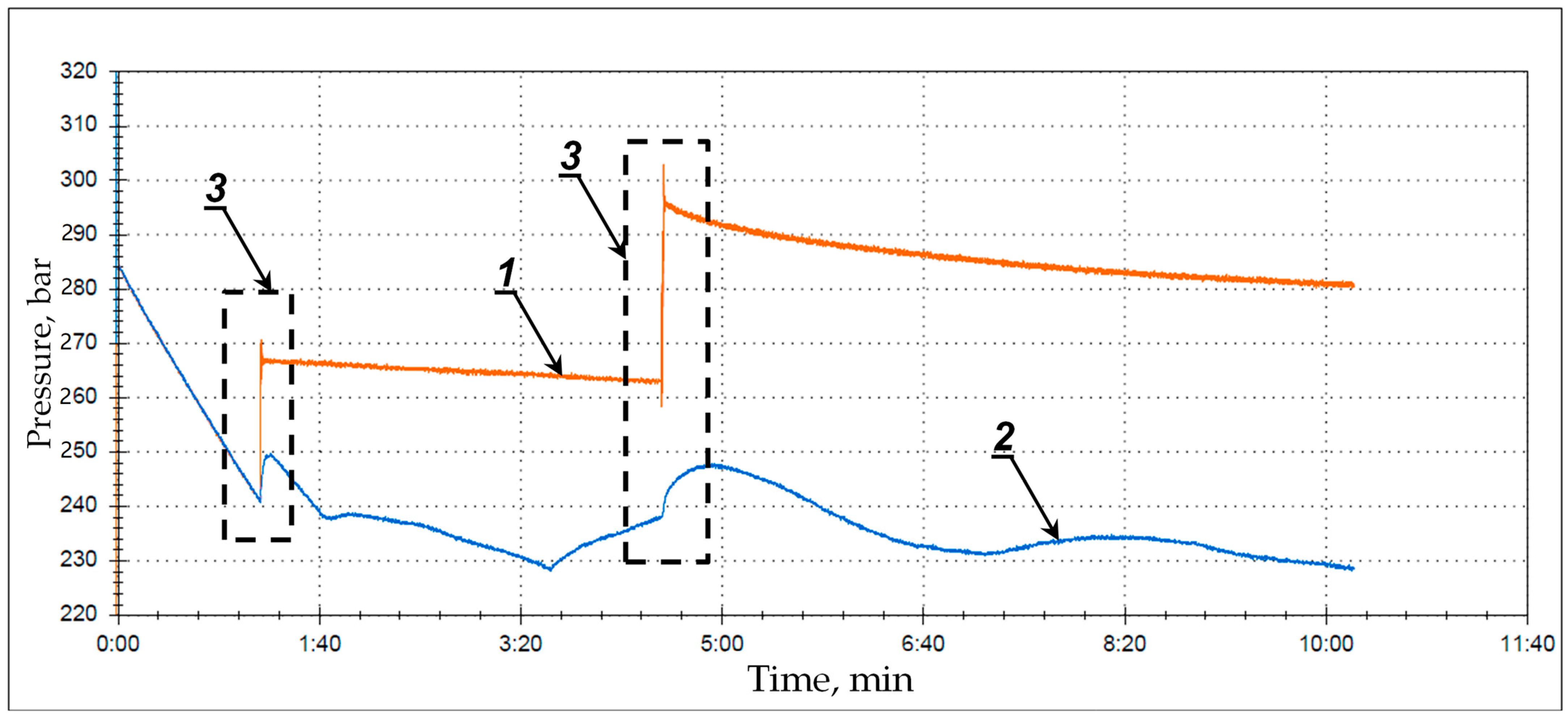
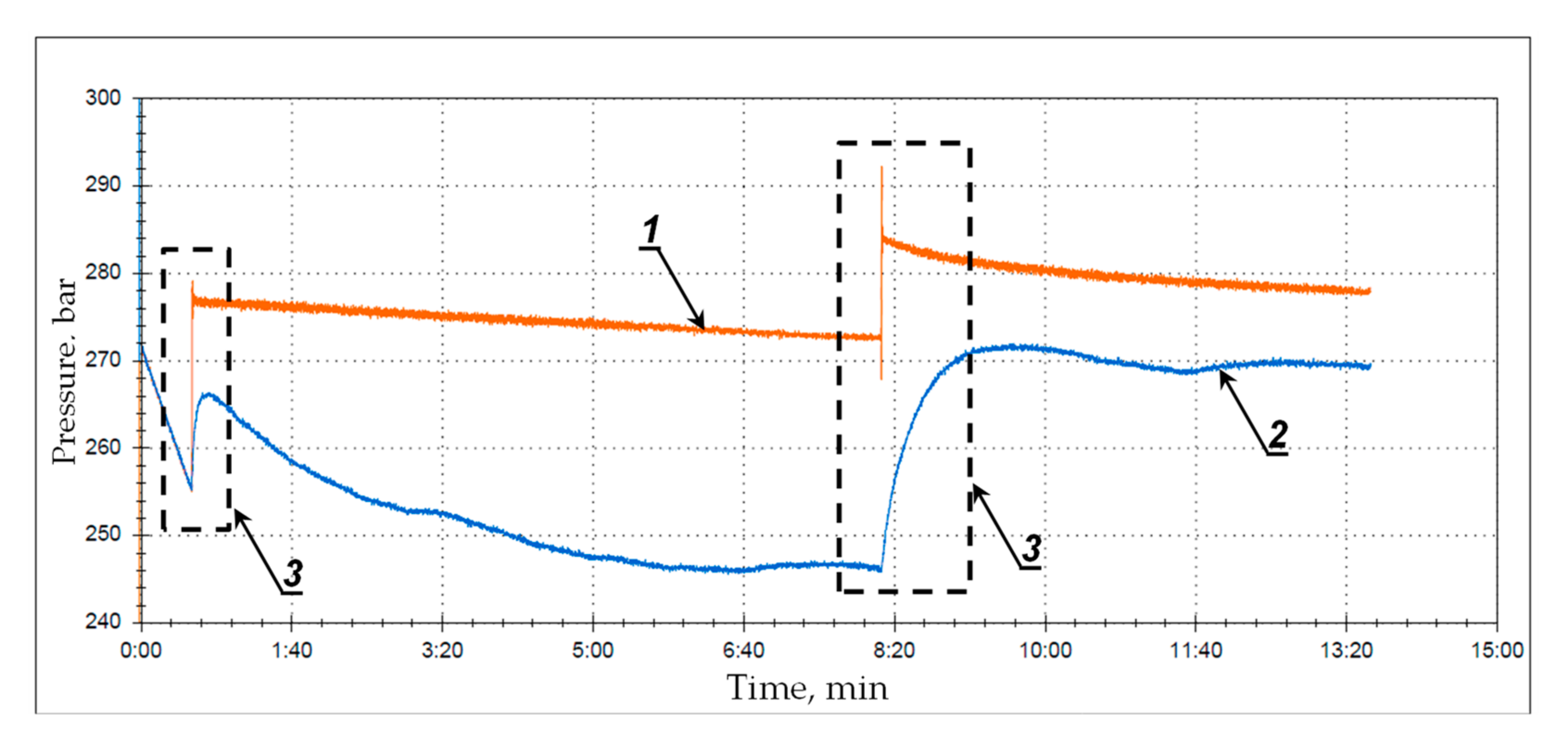
However, in the second phase of the study (Figure 10 and Figure 11), the time was extended to about 10 min, which allowed for a more optimal measurement than shown in Figure 9. The measurements show a pressure drop due to an internal leak at a set pressure of 250 bar.
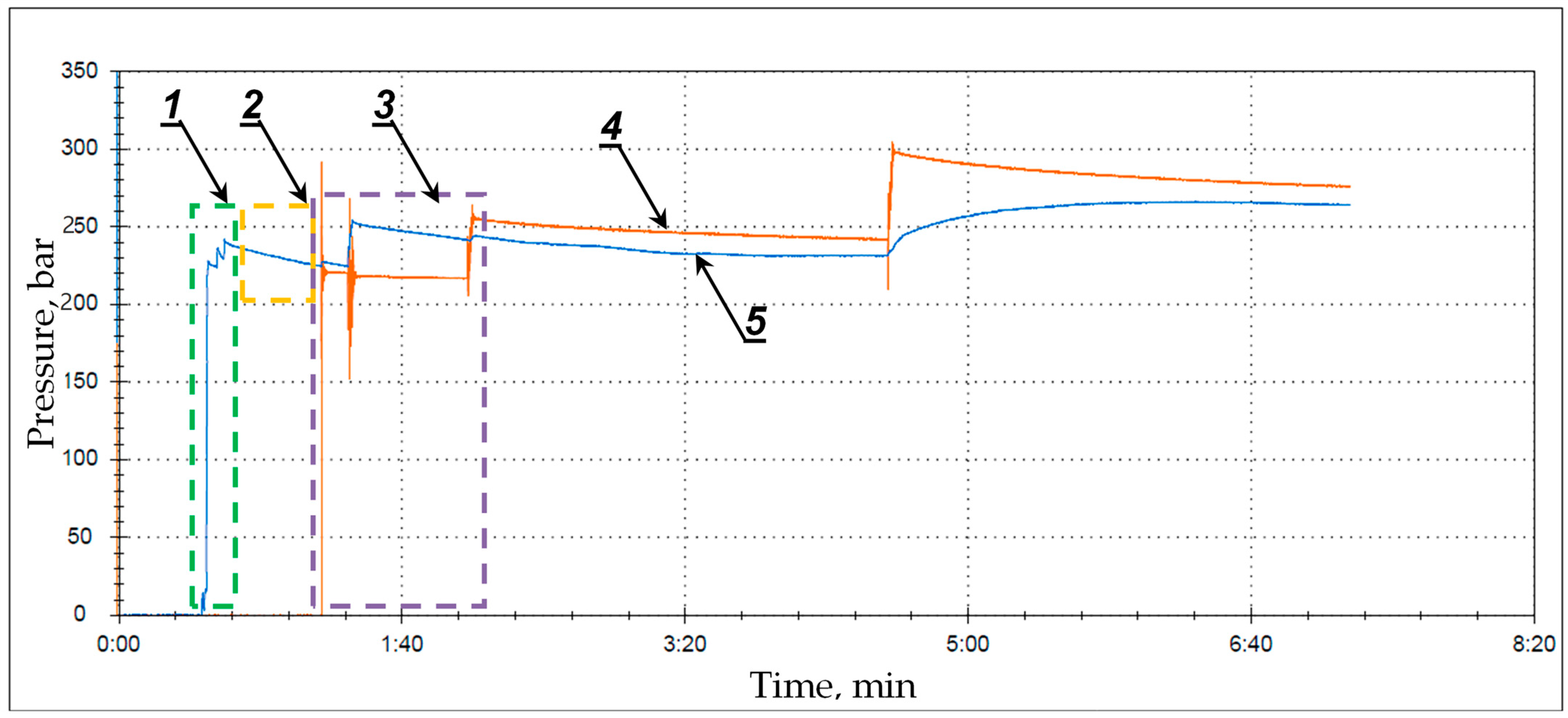
In the third phase of the study, the measurements included the operation of a double block with an additional pressure boost. Figure 12 shows the measurement from the total expansion of the prop, followed by the loss of the load capacity caused by an internal leak. The automatic charging starts after a pressure drop of about 50 bar. The auto-charging function recharges up to 50 bar at a supply pressure of 250 bar.
Figure 13 and Figure 14 show the obtained measurements for the charging function. These graphs show the actual measurements for the boost function up to 50 bar, decreasing due to internal leaks.
The conducted research showed the validity of the established concept. The use of a double-charged block has made it possible to maintain the required working support in a leg with an internal leak. Thus, the solution proposed by the authors helps minimize the effects of possible internal leakage. Thus, the correct operation of the powered roof support is ensured, which is essential for operational safety. The time of loss of load bearing capacity was from 50 to 440 s, and the recharging time was from 10 to 40 s, depending on the supply pressure. Based on Equations (1) and (2), on the basis of the obtained pressure measurements, the working capacity and the actual capacity were calculated. As it results from the tests and calculations, the actual support of a stand with internal leakage may be 18–43% lower than the required working support (depending on the supply pressure). The results from the measurements are illustrated in Figure 14 (obtained test results for the adopted relationships are shown in Figure 15) and summarized in Table 3.

4. Discussion

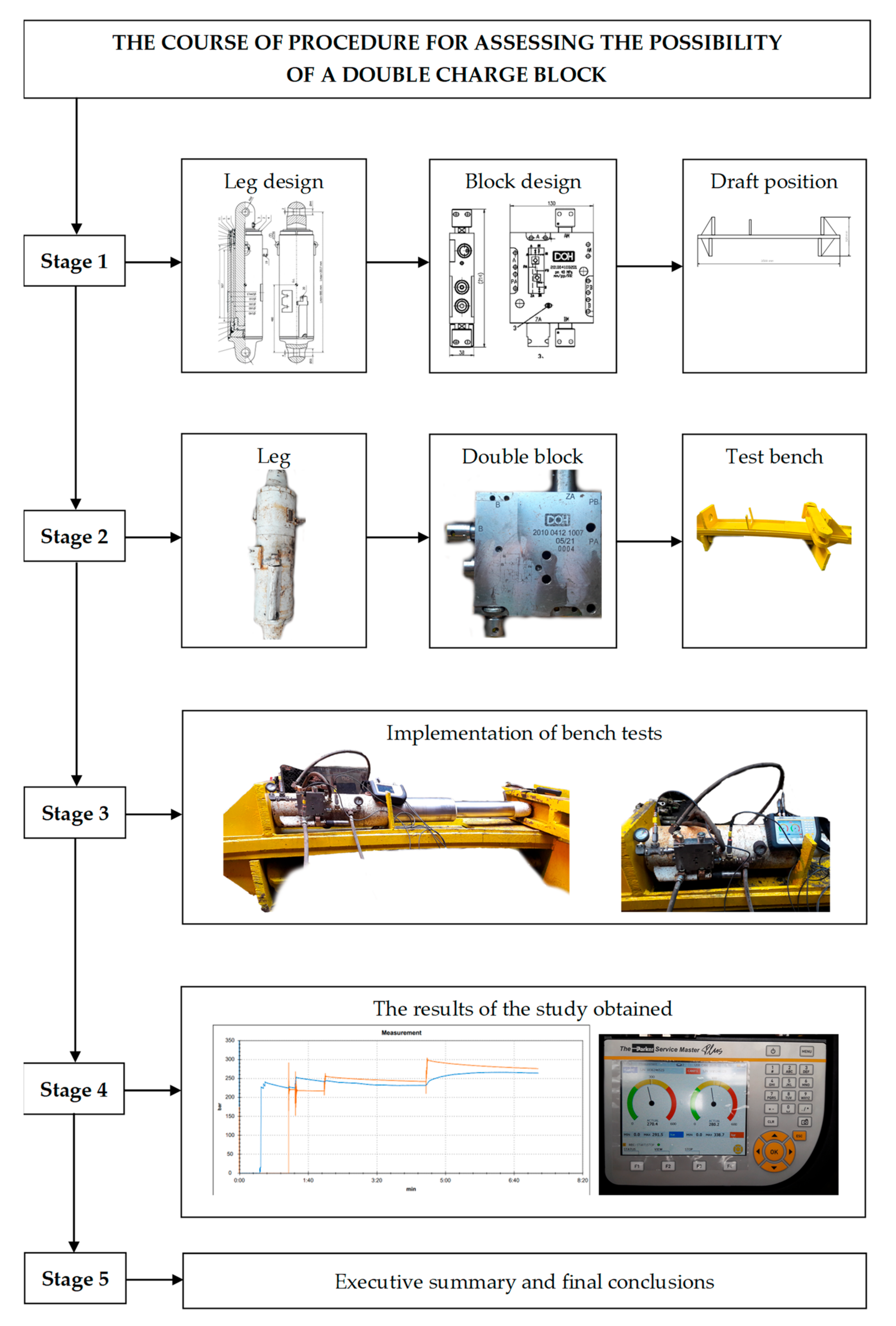
The adopted course of proceedings for assessing suitability based on bench tests of a double block with a charging function is shown in Figure 16. Five stages were proposed to obtain the final results. In stage 1, the focus was on the design for the adopted concept. This task included the development of a prototype version of a double block. As the solutions for the design of the prop had already been developed, it was not a point of concern here. At this stage, a draft of the research stand was created.
In step 2, a hydraulic prop corresponding to the parameters of the double block was prepared. A prototype of the unit was made based on the adopted concept and design. The final result of this stage is the physical preparation of the test stand and the hydraulic prop with the prototype block.
Based on the preparations made in stage 2, we proceed to implement site tests, which constitute stage 3. The recording of measurements was carried out by a special portable measuring system described in Chapter 2; the implementation of the research allowed us to obtain results, which constitute stage 4. The measurement system allowed us to generate graphs of pressure changes over time. The tests included measuring the pressure in the prop’s sub-block space and the block’s boost pressure.
As can be seen in Figure 8, there was a loss of pressure during leg operation, which led to a decrease in support. Despite internal leakage, the required pressure value was maintained in the rack (Figure 11, Figure 12 and Figure 13). Each time the pressure in the sub-piston space of the leg dropped, and the pressure in the block was automatically recharged. Measurements were carried out for different supply pressures from 230 to 300 bar. The loss of support time and recharge time were measured from the measurement records.
The analysis of the research results allowed us to conclude, determining the usefulness and readiness to start the research in real conditions. The adopted course of proceedings, shown in Figure 16, ends with stage 5, summarizing the conclusions drawn.

5. Conclusions

This work presents the method of conducting site tests of a prototype double block with a recharging function. The research analysis was based on the working load capacity equation. The presented structure has been modified for the needs of bench tests. Its modification primarily took into account the losses caused by leaks. In this way, a mathematical record was created, which determined the behavior of the powered roof support during a leak. In the analysis, the internal and external leaks of the prop causing the loss of working load capacity were taken into account. Based on the theoretical analysis recorded with a modified formula for determining the working load capacity during the formation of leaks, work on the change in the hydraulic system of the prop was started. The hydraulic system, or more specifically the support block, is responsible for the prop’s load capacity maintenance. Based on the structural analysis of the currently used solutions, the concept was adopted to develop a prototype of a new block with a recharging function. The idea is to provide working load capacity when the leak develops. The site research was commenced in order to verify the correctness of the presumptions and the thesis. A test stand was prepared (Figure 6), which allowed us to start the research. The test stand was organized in the extraction wall, whose technical efficiency determined that it had a leak on the internal seals. Site tests showed:
(1)
A prototype double block with a recharging function; in order to obtain its optimal parameters, a minimum of 25 MPa must be provided in the main power line.
(2)
During the bench tests, no problems were found with the possible suspension of the charging valve in the block.
(3)
The analysis of the obtained graphs (Figure 12, Figure 13 and Figure 14) of the tested stand with internal leakage concluded that the double block in operational tests should achieve the required operating parameters.
(4)
The results of the conducted tests confirm the correctness of the proposed changes for introducing a double block with a charging function to the powered roof support hydraulic system.

Author Contributions

Conceptualization, D.S. and B.B.; methodology, D.S. and B.B.; software, B.B.; validation, D.S., B.B. and S.Z.; formal analysis, R.D.; investigation, D.S.; resources, R.D.; data curation, S.Z.; writing—original draft preparation, D.S., B.B. and R.D.; writing—review and editing, D.S. visualization, R.D.; supervision, D.S.; project administration, D.S., B.B., and S.Z.; and funding acquisition, D.S., S.Z., and A.J.S.S. All authors have read and agreed to the published version of the manuscript.

Funding

This research received no external funding.

Institutional Review Board Statement

The study was conducted according to the guidelines of the Declaration.

Informed Consent Statement

Not applicable.

Data Availability Statement

Not applicable.

Conflicts of Interest

The authors declare no conflict of interest.

References

  1. Bazaluk, O.; Velychkovych, A.; Ropyak, L.; Pashechko, M.; Pryhorovska, T.; Lozynskyi, V. Influence of Heavy Weight Drill Pipe Material and Drill Bit Manufacturing Errors on Stress State of Steel Blades. Energies 2021, 14, 4198. [Google Scholar] [CrossRef]
  2. Wodecki, J.; Góralczyk, M.; Krot, P.; Ziętek, B.; Szrek, J.; Worsa-Kozak, M.; Zimroz, R.; Śliwiński, P.; Czajkowski, A. Process Monitoring in Heavy Duty Drilling Rigs—Data Acquisition System and Cycle Identification Algorithms. Energies 2020, 13, 6748. [Google Scholar] [CrossRef]
  3. Bortnowski, P.; Gładysiewicz, L.; Król, R.; Ozdoba, M. Energy Efficiency Analysis of Copper Ore Ball Mill Drive Systems. Energies 2021, 14, 1786. [Google Scholar] [CrossRef]
  4. Borkowski, P.J. Comminution of Copper Ores with the Use of a High-Pressure Water Jet. Energies 2020, 13, 6274. [Google Scholar] [CrossRef]
  5. Baiul, K.; Khudyakov, A.; Vashchenko, S.; Krot, P.V.; Solodka, N. The experimental study of compaction parameters and elastic after-effect of fine fraction raw materials. Min. Sci. 2020, 27, 7–18. [Google Scholar] [CrossRef]
  6. Gursky, V.; Krot, P.; Korendiy, V.; Zimroz, R. Dynamic Analysis of an Enhanced Multi-Frequency Inertial Exciter for Industrial Vibrating Machines. Machines 2022, 10, 130. [Google Scholar] [CrossRef]
  7. Bazaluk, O.; Slabyi, O.; Vekeryk, V.; Velychkovych, A.; Ropyak, L.; Lozynskyi, V. A Technology of Hydrocarbon Fluid Production Intensification by Productive Stratum Drainage Zone Reaming. Energies 2021, 14, 3514. [Google Scholar] [CrossRef]
  8. Grzesiek, A.; Zimroz, R.; Śliwiński, P.; Gomolla, N.; Wyłomańska, A. A Method for Structure Breaking Point Detection in Engine Oil Pressure Data. Energies 2021, 14, 5496. [Google Scholar] [CrossRef]
  9. Szurgacz, D.; Zhironkin, S.; Vöth, S.; Pokorný, J.; Spearing, A.J.S.; Cehlár, M.; Stempniak, M.; Sobik, L. Thermal Imaging Study to Determine the Operational Condition of a Conveyor Belt Drive System Structure. Energies 2021, 14, 3258. [Google Scholar] [CrossRef]
  10. Moosavi, F.; Shiri, H.; Wodecki, J.; Wyłomańska, A.; Zimroz, R. Application of Machine Learning Tools for Long-Term Diagnostic Feature Data Segmentation. Appl. Sci. 2022, 12, 6766. [Google Scholar] [CrossRef]
  11. Yang, W.; Zimroz, R.; Papaelias, M. Advances in Machine Condition Monitoring and Fault Diagnosis. Electronics 2022, 11, 1563. [Google Scholar] [CrossRef]
  12. Król, R.; Kisielewski, W. Research of loading carrying idlers used in belt conveyor-practical applications. Diagnostyka 2014, 15, 67–74. [Google Scholar]
  13. Góralczyk, M.; Krot, P.; Zimroz, R.; Ogonowski, S. Increasing Energy Efficiency and Productivity of the Comminution Process in Tumbling Mills by Indirect Measurements of Internal Dynamics—An Overview. Energies 2020, 13, 6735. [Google Scholar] [CrossRef]
  14. Kawalec, W.; Błażej, R.; Konieczna, M.; Król, R. Laboratory Tests on e-pellets effectiveness for ore tracking. Min. Sci. 2018, 25, 7–18. [Google Scholar] [CrossRef]
  15. Adach-Pawelus, K.; Pawelus, D. Influence of Driving Direction on the Stability of a Group of Headings Located in a Field of High Horizontal Stresses in the Polish Underground Copper Mines. Energies 2021, 14, 5955. [Google Scholar] [CrossRef]
  16. Pokorny, J.; Dlouhá, D.; Kucera, P. Study of the necessity of use virtual origin in assessment of selected fire plume characteristics. MM Sci. J. 2016, 5, 1424–1428. [Google Scholar] [CrossRef]
  17. Pokorny, J.; Mozer, V.; Malerova, L.; Dlouhá, D.; Wilkinson, P. A simplified method for establishing safe available evacuation time based on a descending smoke layer. Commun. Sci. Lett. Univ. Zilina 2018, 20, 28–34. [Google Scholar] [CrossRef]
  18. Zimroz, P.; Trybała, P.; Wróblewski, A.; Góralczyk, M.; Szrek, J.; Wójcik, A.; Zimroz, R. Application of UAV in Search and Rescue Actions in Underground Mine—A Specific Sound Detection in Noisy Acoustic Signal. Energies 2021, 14, 3725. [Google Scholar] [CrossRef]
  19. Ziętek, B.; Banasiewicz, A.; Zimroz, R.; Szrek, J.; Gola, S. A Portable Environmental Data-Monitoring System for Air Hazard Evaluation in Deep Underground Mines. Energies 2020, 13, 6331. [Google Scholar] [CrossRef]
  20. Ji, Y.; Ren, T.; Wynne, P.; Wan, Z.; Zhaoyang, M.; Wang, Z. A comparative study of dust control practices in Chinese and Australian longwall coal mines. Int. J. Min. Sci. Technol. 2016, 25, 687–706. [Google Scholar] [CrossRef]
  21. Bortnowski, P.; Król, R.; Nowak-Szpak, A.; Ozdoba, M. A Preliminary Studies of the Impact of a Conveyor Belt on the Noise Emission. Sustainability 2022, 14, 2785. [Google Scholar] [CrossRef]
  22. Gładysiewicz, L.; Król, R.; Kisielewski, W.; Kaszuba, D. Experimental determination of belt conveyors artificial friction coefficient. Acta Montan. Slovaca 2017, 22, 206–214. [Google Scholar]
  23. Kawalec, W.; Suchorab, N.; Konieczna-Fuławka, M.; Król, R. Specific energy consumption of a belt conveyor system in a continuous surface mine. Energies 2020, 13, 5214. [Google Scholar] [CrossRef]
  24. Bajda, M.; Hardygóra, M. Analysis of Reasons for Reduced Strength of Multiply Conveyor Belt Splices. Energies 2021, 14, 1512. [Google Scholar] [CrossRef]
  25. Woźniak, D.; Hardygóra, M. Method for laboratory testing rubber penetration of steel cords in conveyor belts. Min. Sci. 2020, 27, 105–117. [Google Scholar] [CrossRef]
  26. Bajda, M.; Błażej, R.; Hardygóra, M. Optimizing splice geometry in multiply conveyor belts with respect to stress in adhesive bonds. Min. Sci. 2018, 25, 195–206. [Google Scholar] [CrossRef]
  27. Bortnowski, P.; Król, R.; Ozdoba, M. Roller damage detection method based on the measurement of transverse vibrations of the conveyor belt. Eksploat. I Niezawodn. Maint. Reliab. 2022, 24, 510–521. [Google Scholar] [CrossRef]
  28. Patyk, M.; Bodziony, P.; Krysa, Z. A Multiple Criteria Decision Making Method to Weight the Sustainability Criteria of Equipment Selection for Surface Mining. Energies 2021, 14, 3066. [Google Scholar] [CrossRef]
  29. Doroszuk, B.; Król, R. Analysis of conveyor belt wear caused by material acceleration in transfer stations. Min. Sci. 2019, 26, 189–201. [Google Scholar] [CrossRef]
  30. Huang, P.; Spearing, S.; Ju, F.; Jessu, K.V.; Wang, Z.; Ning, P. Control Effects of Five Common Solid Waste Backfilling Materials on In Situ Strata of Gob. Energies 2019, 12, 154. [Google Scholar] [CrossRef] [Green Version]
  31. Wajs, J.; Trybała, P.; Górniak-Zimroz, J.; Krupa-Kurzynowska, J.; Kasza, D. Modern Solution for Fast and Accurate Inventorization of Open-Pit Mines by the Active Remote Sensing Technique—Case Study of Mikoszów Granite Mine (Lower Silesia, SW Poland). Energies 2021, 14, 6853. [Google Scholar] [CrossRef]
  32. Buyalich, G.; Byakov, M.; Buyalich, K. Factors Determining Operation of Lip Seal in the Sealed Gap of the Hydraulic Props of Powered Supports. E3S Web Conf. 2017, 41, 1045. [Google Scholar] [CrossRef]
  33. Rajwa, S.; Tomasz Janoszek, T.; Stanisław Prusek, S. Influence of canopy ratio of powered roof support on longwall working stability—A case study. Int. J. Min. Sci. Technol. 2019, 29, 591–598. [Google Scholar] [CrossRef]
  34. Rajwa, S.; Janoszek, T.; Prusek, S. Model tests of the effect of active roof support on the working stability of a longwall. Comput. Geotech. 2020, 118, 103302. [Google Scholar] [CrossRef]
  35. Bardzinski, P.; Jurdziak, L.; Kawalec, W.; Król, R. Copper ore quality tracking in a belt conveyor system using simulation tools. Nat. Resour. Res. 2020, 29, 1031–1040. [Google Scholar] [CrossRef] [Green Version]
  36. Buyalich, G.; Buyalich, K.; Byakov, M. Factors Determining the Size of Sealing Clearance in Hydraulic Legs of Powered Supports. E3S Web Conf. 2017, 21, 3018. [Google Scholar] [CrossRef] [Green Version]
  37. Juganda, A.; Strebinger, C.; Brune, J.F.; Bogin, G.E. Discrete modeling of a longwall coal mine gob for CFD simulation. Int. J. Min. Sci. Technol. 2020, 30, 463–469. [Google Scholar] [CrossRef]
  38. Janus, J.; Krawczyk, J. Measurement and Simulation of Flow in a Section of a Mine Gallery. Energies 2021, 14, 4894. [Google Scholar] [CrossRef]
  39. Świątek, J.; Janoszek, T.; Cichy, T.; Stoiński, K. Computational Fluid Dynamics Simulations for Investigation of the Damage Causes in Safety Elements of Powered Roof Supports—A Case Study. Energies 2021, 14, 1027. [Google Scholar] [CrossRef]
  40. Dlouhá, D.; Pokorný, J.; Dlouhá, K. Necessity of knowledge about math in safety engineering. In Proceedings of the 14th Conference E-Learning: Unlocking the Gate to Education around the Globe, Prague, Czech Republic, 20–21 June 2019; pp. 380–386. [Google Scholar]
  41. Dlouhá, D.; Dubovský, V. The improvement of the lake Most evaporation estimates. Inż. Miner. 2019, 21, 159–164. [Google Scholar]
  42. Dlouhá, D.; Dubovský, V.; Pospíšil, L. Optimal calibration of evaporation models against Penman-Monteith Equatíon. Water 2021, 13, 1484. [Google Scholar] [CrossRef]
  43. Dubovský, V.; Dlouhá, D.; Pospíšil, L. The calibration of evaporation models against the Penman-Monteith equation on lake Most. Sustainability 2021, 13, 313. [Google Scholar] [CrossRef]
  44. Dlouhá, D.; Hamříková, R. Interactive distance materials of mathematics for VŠB-TU Ostrava. In Proceedings of the 13th Conference Overcoming the Challenges and the Barriers in Open Education, Prague, Czech Republic, 25–26 June 2018; pp. 67–72. Available online: https://www.fast.vsb.cz/230/cs/Veda-a-vyzkum/Publikace/2018/ (accessed on 12 July 2022).
  45. Bortnowski, P.; Gładysiewicz, L.; Król, R.; Ozdoba, M. Models of Transverse Vibration in Conveyor Belt—Investigation and Analysis. Energies 2021, 14, 4153. [Google Scholar] [CrossRef]
  46. Dlouhá, D.; Kozlová, K. Knowledge assessment of student’s high school mathematics. In Proceedings of the 17th Conference on Applied Mathematics (APLIMAT 2019), Bratislava, Slovak Republic, 5–7 February 2019; Volume 1, pp. 243–252. [Google Scholar]
  47. Hamříková, R.; Dlouhá, D. Video tutorials for students of the master’s program. In Proceedings of the 12th Conference Open Education as a Way to a Knowledge Society, Prague, Czech Republic, 26–27 June 2017; pp. 446–451. [Google Scholar]
  48. Dlouhá, D.; Hamříková, R. Our experience with the involvement of students in the creation of study materials. In Proceedings of the 17th Conference on Applied Mathematics (APLIMAT 2019), Bratislava, Slovak Republic, 5–7 February 2019; Volume 1, pp. 301–308. [Google Scholar]
  49. Kumar, R.; Singh, A.K.; Mishra, A.K.; Singh, R. Underground mining of thick coal seams. Int. J. Min. Sci. Technol. 2015, 25, 885–896. [Google Scholar] [CrossRef]
  50. Mo, S.; Tutuk, K.; Saydam, S. Management of floor heave at Bulga Underground Operations—A case study. Int. J. Min. Sci. Technol. 2019, 29, 73–78. [Google Scholar] [CrossRef]
  51. Peng, S.S.; Feng, D.; Cheng, J.; Yang, L. Automation in U.S. longwall coal mining: A state-of-the-art review. Int. J. Min. Sci. Technol. 2019, 29, 151–159. [Google Scholar]
  52. Ralston, J.C.; Hargrave, C.O.; Dunn, M.T. Longwall automation: Trends, challenges and opportunities. Int. J. Min. Sci. Technol. 2017, 27, 733–739. [Google Scholar] [CrossRef]
  53. Ralston, J.C.; Reid, D.C.; Dunn, M.T.; Hainsworth, D.W. Longwall automation: Delivering enabling technology to achieve safer and more productive underground mining. Int. J. Min. Sci. Technol. 2015, 25, 865–876. [Google Scholar] [CrossRef]
  54. Klishin, S.V.; Klishin, V.I. Effect of packer design on hydraulic fracturing of coal seam. E3S Web Conf. 2021, 330, 01002. [Google Scholar] [CrossRef]
  55. Prostański, D. Empirical Models of Zones Protecting Against Coal Dust Explosion. Arch. Min. Sci. 2017, 62, 611–619. [Google Scholar] [CrossRef] [Green Version]
  56. Frith, R.C. A holistic examination of the load rating design of longwall shields after more than half a century of mechanised longwall mining. Int. J. Min. Sci. Technol. 2015, 26, 199–208. [Google Scholar] [CrossRef]
  57. Uth, F.; Polnik, B.; Kurpiel, W.; Baltes, R.; Kriegsch, P.; Clause, E. An innovate person detection system based on thermal imaging cameras dedicate for underground belt conveyors. Min. Sci. 2019, 26, 263–276. [Google Scholar] [CrossRef]
  58. Szurgacz, D.; Zhironkin, S.; Pokorný, J.; Spearing, A.J.S.; Vöth, S.; Cehlár, M.; Kowalewska, I. Development of an Active Training Method for Belt Conveyor. Int. J. Environ. Res. Public Health 2022, 19, 437. [Google Scholar] [CrossRef] [PubMed]
  59. Wang, J.; Wang, Z. Systematic principles of surrounding rock control in longwall mining within thick coal seams. Int. J. Min. Sci. Technol. 2019, 29, 591–598. [Google Scholar] [CrossRef]
  60. Gil, J.; Kołodziej, M.; Szurgacz, D.; Stoiński, K. Introduction of standardization of powered roof supports to increase production efficiency of Polska Grupa Górnicza, S.A. Min. Inform. Autom. Electr. Eng. 2019, 56, 33–38. [Google Scholar] [CrossRef]
  61. Ji, Y.; Zhang, Y.; Huang, Z.; Shao, Z.; Gao, Y. Theoretical analysis of support stability in large dip angle coal seam mined with fully-mechanized top coal caving. Min. Sci. 2020, 27, 73–87. [Google Scholar]
  62. Jixiong, Z.; Spearing, A.J.S.; Xiexing, M.; Shuai, G.; Qiang, S. Green coal mining technique integrating mining-dressing-gas draining-backfilling-mining. Int. J. Min. Sci. Technol. 2017, 27, 17–27. [Google Scholar]
  63. Xiaozhen, W.; Jialin, X.; Weibing, Z.; Yingchun, L. Roof pre-blasting to prevent support crushing and water inrush accidents. Int. J. Min. Sci. Technol. 2012, 22, 379–384. [Google Scholar]
  64. Krauze, K.; Mucha, K.; Wydro, T.; Pieczora, E. Functional and Operational Requirements to Be Fulfilled by Conical Picks Regarding Their Wear Rate and Investment Costs. Energies 2021, 14, 3696. [Google Scholar] [CrossRef]
  65. Kotwica, K.; Stopka, G.; Kalita, M.; Bałaga, D.; Siegmund, M. Impact of Geometry of Toothed Segments of the Innovative KOMTRACK Longwall Shearer Haulage System on Load and Slip during the Travel of a Track Wheel. Energies 2021, 14, 2720. [Google Scholar] [CrossRef]
  66. Hu, S.; Ma, L.; Guo, J.; Yang, P. Support-surrounding rock relationship and top-coal movement laws in large dip angle fully-mechanized caving face. Int. J. Min. Sci. Technol. 2018, 28, 533–539. [Google Scholar]
  67. Szurgacz, D.; Zhironkin, S.; Cehlár, M.; Vöth, S.; Spearing, S.; Liqiang, M. A Step-by-Step Procedure for Tests and Assessment of the Automatic Operation of a Powered Roof Support. Energies 2021, 14, 697. [Google Scholar] [CrossRef]
  68. Buyalich, G.; Byakov, M.; Buyalich, K.; Shtenin, E. Development of Powered Support Hydraulic Legs with Improved Performance. E3S Web Conf. 2019, 105, 3025. [Google Scholar] [CrossRef]
  69. Klishin, V.I.; Klishin, S.V. Coal Extraction from Thick Flat and Steep Beds. J. Min. Sci. 2010, 46, 149–159. [Google Scholar] [CrossRef]
  70. Stoiński, K.; Mika, M. Dynamics of Hydraulic Leg of Powered Longwall Support. J. Min. Sci. 2003, 39, 72–77. [Google Scholar] [CrossRef]
  71. Szurgacz, D. Dynamic Analysis for the Hydraulic Leg Power of a Powered Roof Support. Energies 2021, 14, 5715. [Google Scholar] [CrossRef]
  72. Szurgacz, D.; Borska, B.; Diederichs, R.; Zhironkin, S. Development of a Hydraulic System for the Automatic Expansion of Powered Roof Support. Energies 2022, 15, 680. [Google Scholar] [CrossRef]
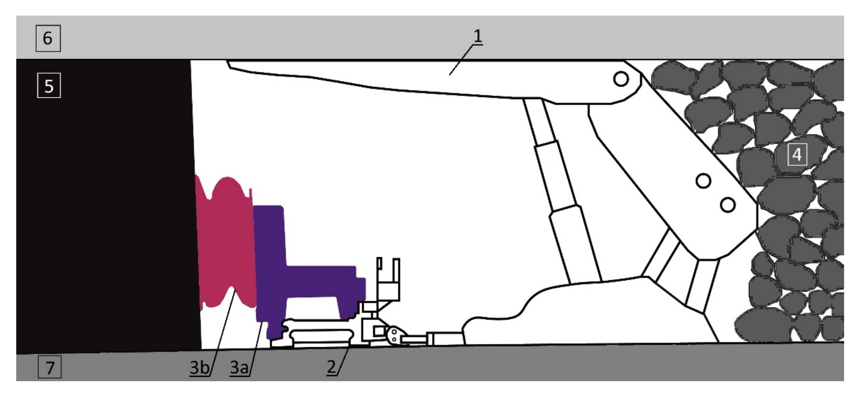
Figure 1. Mechanized wall complex, where 1—powered roof support, 2—longwall scraper conveyor, 3a—shearer, 3b—cutting unit, 4—goafs, 5—coal, 6—roof, and 7—floor.
Energies 15 06061 g001
Figure 2. Powered roof support, where 1—canopy, 2—hydraulic prop, 3—canopy support, 4—the shield support, 5—floor base, 6—lemniscate mechanism, 7—shifting system, 8—minimum expansion height, and 9—maximum expansion height.
Energies 15 06061 g002
Figure 3. Conceptual diagram of the use of seals to protect the hydraulic prop from external and internal leakage, where 1—cylinder, 2—core I, 3—core II, 4—piston, and 5—bottom valve; (a) construction of the gland node, where 1—inner sealing ring, 2—inner guide rings, 3—inner scraper ring, 4—outer scraper ring, 5—outer sealing ring, 6—static seal, and 7—outer guide rings; and (b) piston node, where 1—inner sealing ring, 2—outer guide ring, 3—inner guide rings, 4—outer sealing ring, and 5—outer guide rings.
Energies 15 06061 g003
Figure 4. Analysis of the development of internal leakage for the prop of powered roof support.
Energies 15 06061 g004
Figure 5. The concept and design of a double block with a recharging function for the powered roof support hydraulic system.
Energies 15 06061 g005
Figure 6. Test site, where (a) draft position, (b) during construction, and (c) finished post.
Energies 15 06061 g006
Figure 7. The portable measuring device, where 1—CAN connection cable; 2—analogue connection cable; 3—analogue temperature sensor; 4—analogue turbine flow meter; 5—analogue pressure/temperature sensor; 6—CAN Y-junction; 7—CAN pressure/temperature sensor; and 8—CAN terminating resistor.
Energies 15 06061 g007
Figure 8. Test site with the tested double block, where 1—frame of test site, 2—hydraulic prop, 3—pressure sensor for the sub-block space, 4—double block with pressure boost, 5—pressure sensor for the supra-block space, and 6—measuring device.
Energies 15 06061 g008
Figure 9. Measurement of pressure in the sub-piston space of the prop taking into account leakage.
Energies 15 06061 g009
Figure 10. Measurement of pressure in the sub-piston space of the prop taking into account leakage.
Energies 15 06061 g010
Figure 11. Measurement of pressure in the sub-piston space of the prop taking into account leakage.
Energies 15 06061 g011
Figure 12. Testing of the prop along with the double block with pressure boost, where 1—prop expansion phase, 2—area of the loss of load capacity, 3—automatic start of recharging, 4—boost pressure in the block, and 5—pressure in the sub-piston space of the prop.
Energies 15 06061 g012
Figure 13. Testing of the prop along with the double block with pressure boost, where 1—boost pressure in the block, 2—pressure in the sub-piston space of the prop, and 3—automatic pressure charging.
Energies 15 06061 g013
Figure 14. Testing of the prop along with the double block with pressure boost, where 1—boost pressure in the block, 2—pressure in the sub-piston space of the prop, and 3—automatic pressure charging.
Energies 15 06061 g014
Figure 15. Obtained test results for the adopted relationships: 1—working load capacity, 2—actual load capacity, 3—time of loss capacity, and 4—time of pressure boost.
Energies 15 06061 g015
Figure 16. Course of proceedings for assessing suitability based on bench tests of a double block with a charging function.
Energies 15 06061 g016
Table 1. Technical characteristics of the prototype double block.
Operation RangeWork Unit
Nominal pressure480 bar
Flow diameterØ 10
Maximum flow400 l/min
Number of check valve cartridges3
Work temperature40 °C ÷ 60 °C
Table 2. Technical characteristics of the hydraulic prop of the powered roof support.
Operation RangeWork Unit
Working Diameter210 mm/160 mm
Supply pressure25 ÷ 30 MPa
Nominal pressure40 MPa
Initial load capacity865 ÷ 1039 kN
Nominal load capacity1385 kN
Hydraulic I stage stroke 507 mm
Hydraulic II stage stroke 515 mm
Min. length995 mm
Max. length2017 mm
Overload factor2
Table 3. The values obtained based on the research carried out.
Supply Pressure CzWorking Load Capacity
Fw
Time of Loss Load Capacity
Tu
Time of Pressure Boost
Td
Actual Load Capacty
Frz
300 bar1039 kN440 s40 s848 kN
290 bar1004 kN140 s30 s814 kN
280 bar969 kN70 s18 s796 kN
270 bar935 kN70 s15 s762 kN
260 bar900 kN100 s15 s589 kN
250 bar865 kN80 s15 s519 kN
240 bar831 kN60 s10 s519 kN
230 bar796 kN50 s10 s450 kN
Publisher’s Note: MDPI stays neutral with regard to jurisdictional claims in published maps and institutional affiliations.