Article

Numerical Simulation of Transient Combustion and the Acoustic Environment of Obstacle Vortex-Driven Flow

1
Department of Basic Science and Related Studies, Mehran University of Engineering and Technology, Jamshoro 76062, Pakistan
2
Department of Basic Science and Related Studies, Quaid-e-Awam University of Engineering, Science and Technology, Nawabshah 67480, Pakistan
3
Department of Mechanical Engineering, Mehran University of Engineering and Technology, Jamshoro 76062, Pakistan
4
Department of CFD, Institute of Space Technology, Karachi 75270, Pakistan
*
Author to whom correspondence should be addressed.
Energies 2022, 15(16), 6079; https://doi.org/10.3390/en15166079
Submission received: 27 June 2022 / Revised: 11 August 2022 / Accepted: 15 August 2022 / Published: 22 August 2022
(This article belongs to the Special Issue Advanced Studies in Clean and Green Energy Technologies)

Abstract

:
Solid fuel combustion in a chamber does not necessarily occur at a constant rate and may show fluctuations due to variables such as varying burning rates, chamber pressure, and residual combustion. These variables can cause the fuel to burn disproportionately. The acoustic environment of obstacle vortex-driven flow due to transient combustion with pressure oscillations in a solid fuel chamber is numerically investigated in the present study. Solid fuel combustion is considered transient, and flow characteristics of the present problem are governed by large eddies shed from an obstacle. Since unsteady Reynolds-averaged Navier-Stokes (URANS) simulations are not appropriate to compute the present flow phenomenon, therefore, a detached eddy simulation (DES) is performed to precisely predict the flow behavior. Simulation of steady-state combustion is carried out to validate the numerical results with available experimental data from the literature. The simulation of transient combustion shows that if the combustion frequency is close to the chamber’s modal frequency of the chamber, its amplitude increases greatly and creates an acute acoustic environment. This will result in fuel savings. The amplitude of pressure oscillation up to 18% and 5% of mean pressure are evident at the first and second mode of forced oscillation frequencies respectively. Interestingly, it is also found that pressure oscillation always occurs at inlet mass flux disturbance frequency and not between the disturbance and natural frequency of the chamber. As a result, it is evident that the combustion process or chamber configuration could be modified to ensure that both frequencies are far away enough to interact and create both a harsh acoustic environment and sufficient fuel to burn disproportionately.

1. Introduction

During the last thirty years, the instability problem in solid fuel combustion chambers has attracted much attention from researchers and scientists [1]. Combustion chambers face several persistent challenges and problems caused by combustion instability. There are numerous reasons for combustion instability in a solid fuel combustion chamber, such as pressure-coupled responses, velocity-coupled responses, and vortex-acoustic coupling [2]. Vortex-acoustic coupling is one of the key reasons for combustion instability. Vortices are shed from solid fuel surfaces/corners or from obstacles placed inside chamber which interact with the acoustic environment of the chamber [3]. Solid rocket motors (SRM) combustion instabilities are affected by aluminum droplet combustion and alumina residue behavior. These droplets generate slag material inside the motor and reduces the motor performance. Moreover, alumina slag deposition at the motor aft-end can lead to thermal protection damage, liquid agglomerates ejecting through the nozzle, and pressure disturbances and trust imbalance. Via the impingement of the vortices on the nozzle and other obstacles, SRMs can suffer from pressure oscillations caused by vortex shedding and acoustic feedback [4]. To ensure that their propellant grains are segmented, large solid propellant boosters, such as the Ariane 5 accelerator as shown in Figure 1, are constructed with submerged nozzles and segmented propellant grains. The propellant grains are separated by two inhibitor rings that ensure thermal protection [5].
Furthermore, the instability may also be produced due to the unsteady combustion of solid fuel as it generates periodic mass flux inlet from boundaries. Scale resolving simulation (SRS) methods such as the detached eddy simulation (DES) method is recommended to compute flow having vortex shedding and unsteady combustion [4].
Pierre Wolf et al. [6] investigated the feasibility of using LES to study combustion instabilities in annular gas turbine combustors. LES is used as a design tool typically for problems involving combustion instabilities. It is applied to the exact geometry and for the real operating parameters of the engine. To avoid uncertainties on boundary conditions, the chamber casing is also computed. The computational domain starts after the inlet diffuser and ends at the throat of the high-pressure stator [6]. The flow field structure showed a planar signature consisting of counter-rotating vortices in a staggered configuration on the axial plane of the combustion chamber. The combustion chamber was the ignition source of the periodic heat release. It has been confirmed that the influence of the precessing vortex core (PVC) on the flame surface and heat release is an important factor in triggering combustion instability. The role of the precessing vortex core in two combustion regimes in a model combustor was also examined through LES [7]. Combustion instability produces large pressure and force amplitude [8]. During vortex shedding, the combustion chamber can be excited to create acoustic modalities. The growth of these modalities is most incredible when the characteristic frequency of the vortex shedding corresponds to the natural frequency of the chamber [9,10]. The pressure oscillation frequency synchronizes the acoustic frequency of the combustion chamber, and this phenomenon is called acoustic instability [11]. The numerical code [12] provided an accurate simulation of the frequencies while overestimating the pressure oscillation levels. Experiments in [13] were carried out and mathematical models were developed to investigate the vortex shedding frequency caused by the protrusion of inhibitors into the flow field of a solid fuel combustion chamber. Zhao [14] summarized the progress made in implementing acoustic dampers on engine systems, including the challenges they faced. According to Dotson [15], these combustion instabilities have acoustic correlations between pressure oscillations and modes, converging on the fact that pressure oscillations and modalities are related. In a small-scale solid fuel combustion chamber, M. Bernardini [16] investigated the coupling between vortex shedding and pressure oscillations. In addition, Su et al. [2] discussed the dependency of the vortex-shedding-induced pressure oscillations on the position and temperature of the thermal inhibitor placed inside the combustion chamber. Anthoine and Lema [17] worked at 3D-shaped inhibitors that attenuated pressure fluctuations, especially when the cross-section of the opening was increased. The asymmetric inhibitor reduces pressure oscillations in cross-section. Zhang et al. [18] examined the amplitudes created by a mass flux placed in front of a pressure antinode. According to Anthoine [19] the maximum resonance amplitude is highly dependent on the nozzle design. The sound pressure level increases linearly with the nozzle cavity volume. Su et al. [2] found that the acoustic frequency is altered by changing the gas temperature when the chamber configuration is fixed. The natural acoustic frequency is highly dependent on the gas temperature. F. Stella et al. [12] investigated the solid fuel combustion chamber having periodic inlet mass flux condition. Jia, Y et al. [20] proved that the stable combustion temperatures can be provided when solid fuel sizes are consistent. Saha and Chakraborty [21] also studied the periodic inlet mass flux effect using a pressure-coupled response function. Zhang et al. [22] performed numerical simulations to investigate the effects of the head end cavity on resonance suppression in a solid fuel combustion chamber. Katona et al. [23] performed numerical simulations of gaseous flames in combustion chamber applications and considered fundamental flow aspects of combustion instabilities in a swirl concept in the context of the Reynolds-averaged Navier Stokes (RANS) equations for gaseous flames. Cristian R. et al. [24] investigated direct numerical simulations of transient turbulent jets and vortex-interface interactions and obtained numerical solutions for a range of both Reynolds (Re) and Weber (We) numbers.
From the literature review, it can be revealed that all of the studies are related to the solid fuel combustion chamber, and instability is analyzed numerically. However, these studies do not have detailed descriptions of various unsteady combustion flow fields and their effect on the acoustic environment. Therefore, the present research aims to investigate the effect of unsteady combustion on the acoustic environment of a combustion chamber which has obstacle vortex shedding. The present study considers periodic inlet mass flux disturbance to incorporate unsteady combustion. Detached eddy simulations (DES) of Ansys fluent are performed to compute flow behavior. User defined function (UDF) is coupled with Ansys fluent to impose the periodic inlet mass flux disturbance boundary condition. Pressure oscillations for steady state combustion and inlet mass flux disturbance are recorded at eight different chamber locations. Fast Fourier transform (FFT) has been performed to obtain an acoustic environment. The effect of the inlet disturbance frequency on the pressure oscillations in the chamber is analyzed.

2. Methodology

The DES (detached eddy simulation) method is used to calculate the flow physics. It employs a hybrid technique that switches explicitly between RANS and LES models based on the local grid spacing and the turbulent length scale. Numerical validation is carried out by using steady-state combustion.

2.1. Numerical Method

Practical flows are often very complex and turbulent. Flows suffering from vortex-driven pressure oscillations generally have high frequencies. They may have boundary layer separation and reattachment, vortex formation and dynamics, expansion fan and stagnation points, chemical kinetics and residual combustion, laminar and turbulent flow regions, etc. A wide range of length and time scales is also available. The largest eddy size is generally comparable to shear layer thickness, while the smallest eddy size depends on turbulent kinetic energy dissipation. An analytical solution for such a complex flow is not possible. Experiments are costly, time-consuming, and consist of practical limitations. Computational fluid dynamics (CFD) is a tool used to get inside detail and precise results within cost and time constraints. Accurate flow physics prediction and true capturing of vortex dynamics require precise turbulence computation. Available literature confirmed that turbulence modeling dissipates vortex dynamics and is not appropriate to capture real flow physics. Direct numerical simulation (DNS), large eddy simulation (LES), or at least detached eddy simulation (DES) are indispensable for the computation of true physics of vortex-driven flow instability. DNS requires a very large computation time and is still not feasible for practical problems. Recent growth in computational power has allowed researchers to use LES for the computation of vortex-driven flow instability [25]. LES is robust as compared to DNS and provides accurate results for large eddies in contrast to Reynolds average Navier stocks (RANS). Large eddies play a key role in the transportation of mass, momentum, energy, and other scalars. Large eddy formation and dynamics depend on problem configuration, mean flow, and initial and boundary conditions. In contrast, small eddies are universal and isotropic. Spalart Allmaras (SA), k-ε, or k-ω turbulence model may predict small eddies as they are universal and isotropic but large eddy dynamics are difficult to envisage through turbulence modeling as they are more problem depended. LES overcomes this issue by resolving large-scale eddies while modeling small-scale structures. LES suffer in boundary layer region where large eddies become small and Reynolds number-depended resolution is required for accurate computations. The classical Smagorinsky LES model also suffers in laminar shear flows where eddy-viscosity does not become zero. Wall-adapting local eddy-viscosity (WALE) method is used to capture turbulent shear layer flows while the wall-modeled LES (WMLES) is applied to reduce the strict near-wall grid resolution requirements of wall-resolved LES. WMLES switches to zero-equation RANS in the wall adjacent region, hence avoiding the high grid resolution requirement of LES. Detached eddy simulations (DES) are used to switch from LES to RANS in the wall adjacent region depending on mesh resolution. One or two-equation RANS turbulence model is used in DES. Continuity, momentum, and energy equations of compressible flow are solved in the present study. These equations are filtered through the Favre filter to obtain LES governing equations [3]. The filter operator is given as follows:
˜ = ρ ¯ ρ ¯
The governing equations are transformed to:
ρ ¯ t + ρ ¯ u ˜ i x i = 0
ρ ¯ u ˜ i i t + ρ ¯ u ˜ i u ˜ j x j j = ( σ ˜ i j τ i   j S G S ) x j p ¯ x i
ρ ¯ e ˜ t + ρ ¯ u ˜ i e ˜ x i = ( p u ˜ i q i ¯ + u ˜ i σ ˜ i j H i S G S Θ S G S ) x i
The perfect gas equation of state is
p = ρ R T
where “ ¯ ” represents Reynolds average, and “ ˜ ” indicates the Favre average. The SGS stress τ i   j S G S is obtained from
τ i j S G S = 2 μ t ( S ˜ i j 1 3   S ˜ k k   δ i j ) + 2 3   ρ ¯   k S G S δ i j
here σ i j represents stress tensor due to molecular viscosity, which is calculated as
σ ˜ i j = μ ( u ˜ i x j + u ˜ j x i ) 2 3 μ u ˜ k x k   δ i j
The heat flux q i ¯ is given as
q i ¯ = λ   ¯ T ˜ x i
the thermal conductivity is represented by λ   ¯ and defined as;
λ   ¯ = C p μ / P r
The gradient hypothesis is used to define SGS enthalpy term present in the energy equation
H i   S G S = μ t / P r H i x i
where the SGS viscous work Θ i S G S , kinetic energy k S G S , the Favre filtered strain rate tensor S ˜ i j , the SGS eddy viscosity term μ t , and the mixing length for sub-gird scales L s are defined as
Θ S G S = C ε ρ ¯   ( k S G S ) 3 / 2 V 1 / 3
The SGS kinetic energy k S G S is defined as
k S G S = C i V 2 3   S ˜ i j S ˜ j i
The Favre filtered strain rate tensor S ˜ i j is defined as
S ˜ i j = 1 2 ( u ˜ i x j + u ˜ j x i )
The SGS eddy viscosity term μ t is defined as
μ t = ρ ¯ L s 2 ( S i j d S i j d ) 3 / 2 ( S ¯ i j S ¯ i j ) 5 / 2 + ( S i j d S i j d ) 5 / 4
The mixing length for sub-gird scales L s is defined as;
L s = min ( k d ,   C w V 1 / 3 )
here k, d, C w and V represents the Von Karman constant, the distance to the closet wall, the WALE constant, and the computational cell volume, respectively. Where S i j d is expressed as
S i j d = 1 2 ( u ˜ i x k   u ˜ k x j + u ˜ j x k u ˜ k x i ) 1 3 u ˜ k x k u ˜ k x k δ i j
Here
k = 0.40 p r = 0.85 C ε = 1.1 C I = 0.0066
The WALE constant C w is generally taken as 0.5.

2.2. Test Case Description

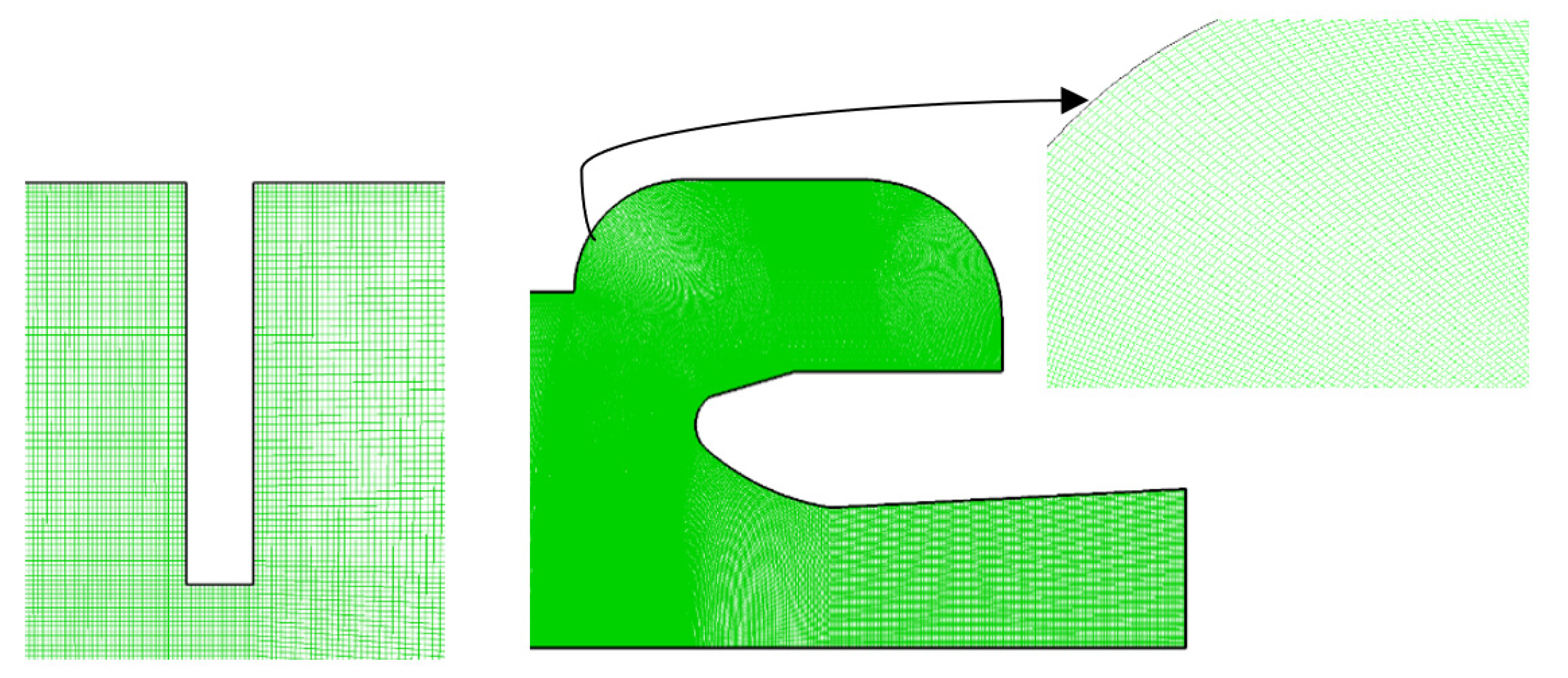
Anthoine’s test case consists of an annular inhibitor which is used in the present study [5]. The author performed experiments to study obstacle vortex-driven pressure fluctuation. Its combustion chamber consists of a cylindrical chamber, nozzle, and annular inhibitor as shown in Figure 2. A structured grid is generated using Gridgen 15 software by taking the geometrical measurements from [5]. It is generated to perform detached eddy simulation (DES). A grid near the inhibitor and nozzle with an exploded view is shown in Figure 3.

2.3. Boundary Conditions

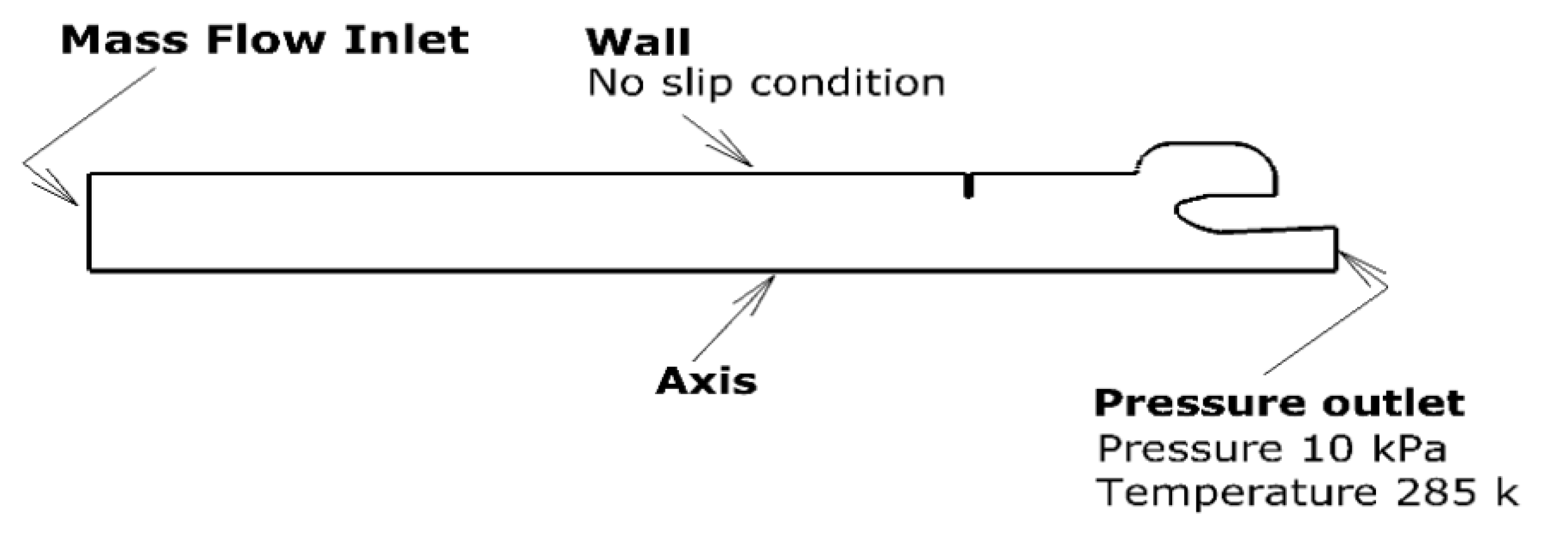
No slip boundary condition with 285 K isothermal temperature is applied at the nozzle and inhibitor wall. Axisymmetric 2D solver is used. Periodic mass flux inlet of 66.3 + 22.1   sin 2 π f t ,   kg / ( m 2 · s ) is applied through UDF to simulate transient combustion. Applied boundary conditions are shown in Figure 4. Pressure time histories at eight different points are recorded to study the acoustic environment of obstacle vortex-driven flow due to transient combustion. The time step was 5 × 10⁻⁵ s based on a Courant-Friedrichs-Lewy number that was always smaller than 0.5. The location of the points are shown in Figure 5.

2.4. Validation of Numerical Methodology

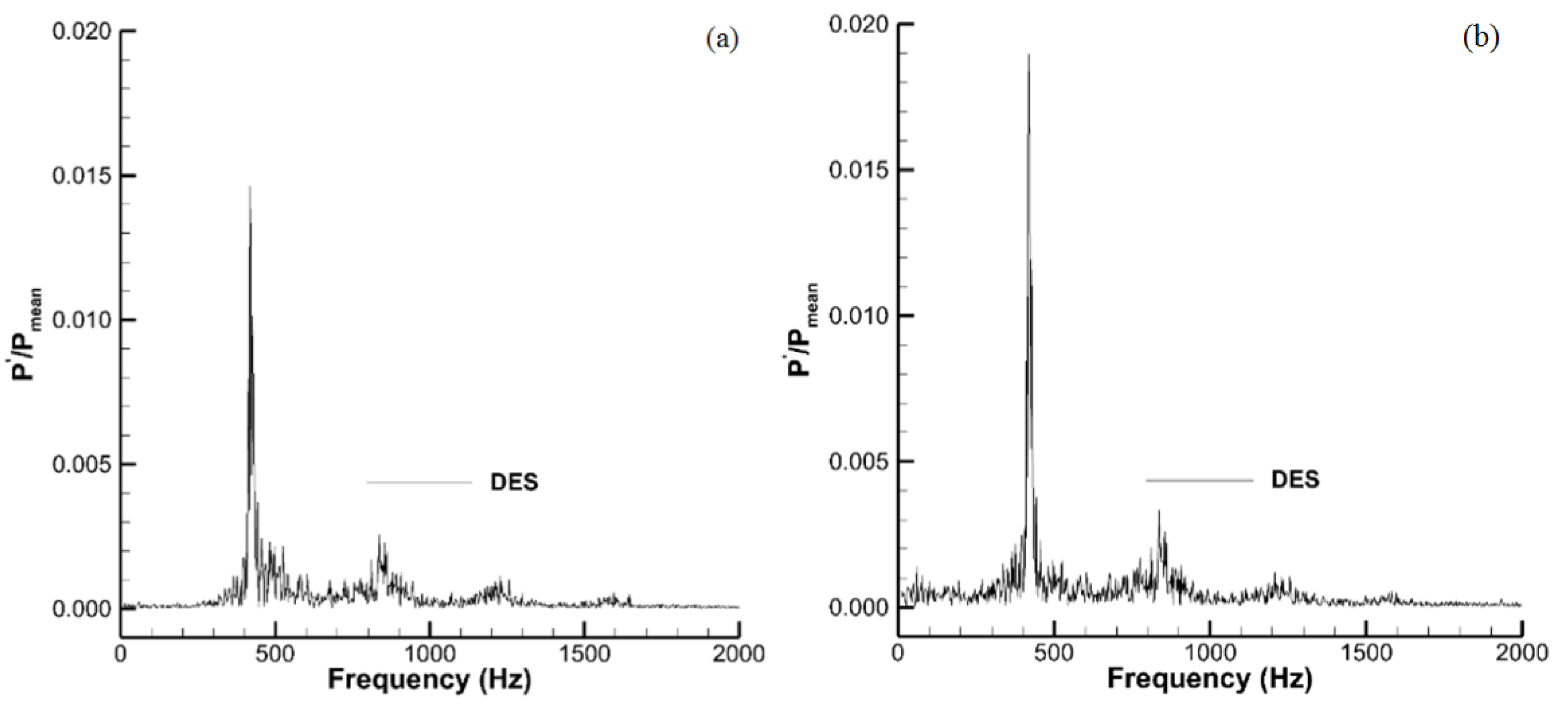
Detached eddy simulation (DES) of steady-state combustion is performed to validate the numerical methodology. Computed modal frequencies at point 1 and point 3 are presented in Figure 6 and given in Table 1. Results depict that DES is reasonably good to compute obstacle vortex-driven flow. DES is used in the present study to investigate the acoustic environment of obstacle vortex-driven flow field due to transient combustion of fuel.

3. Result and Discussion

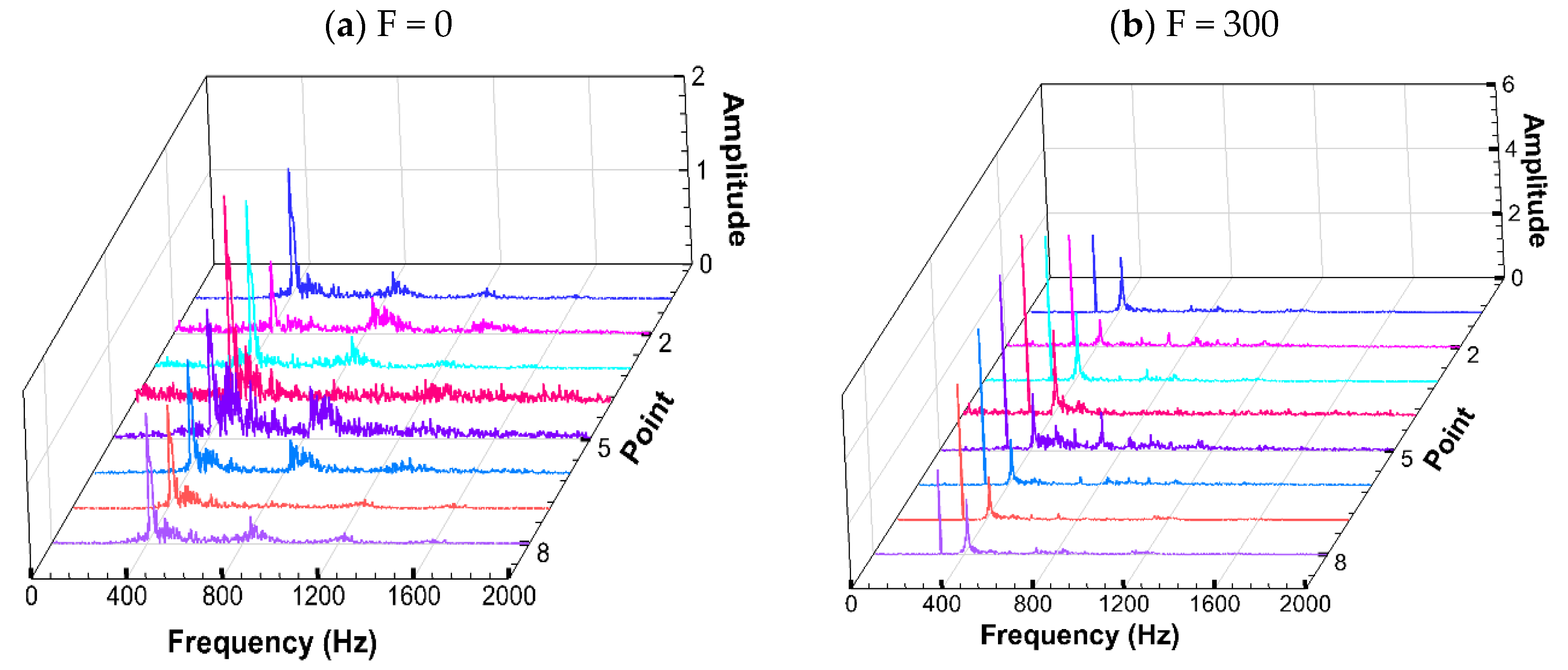
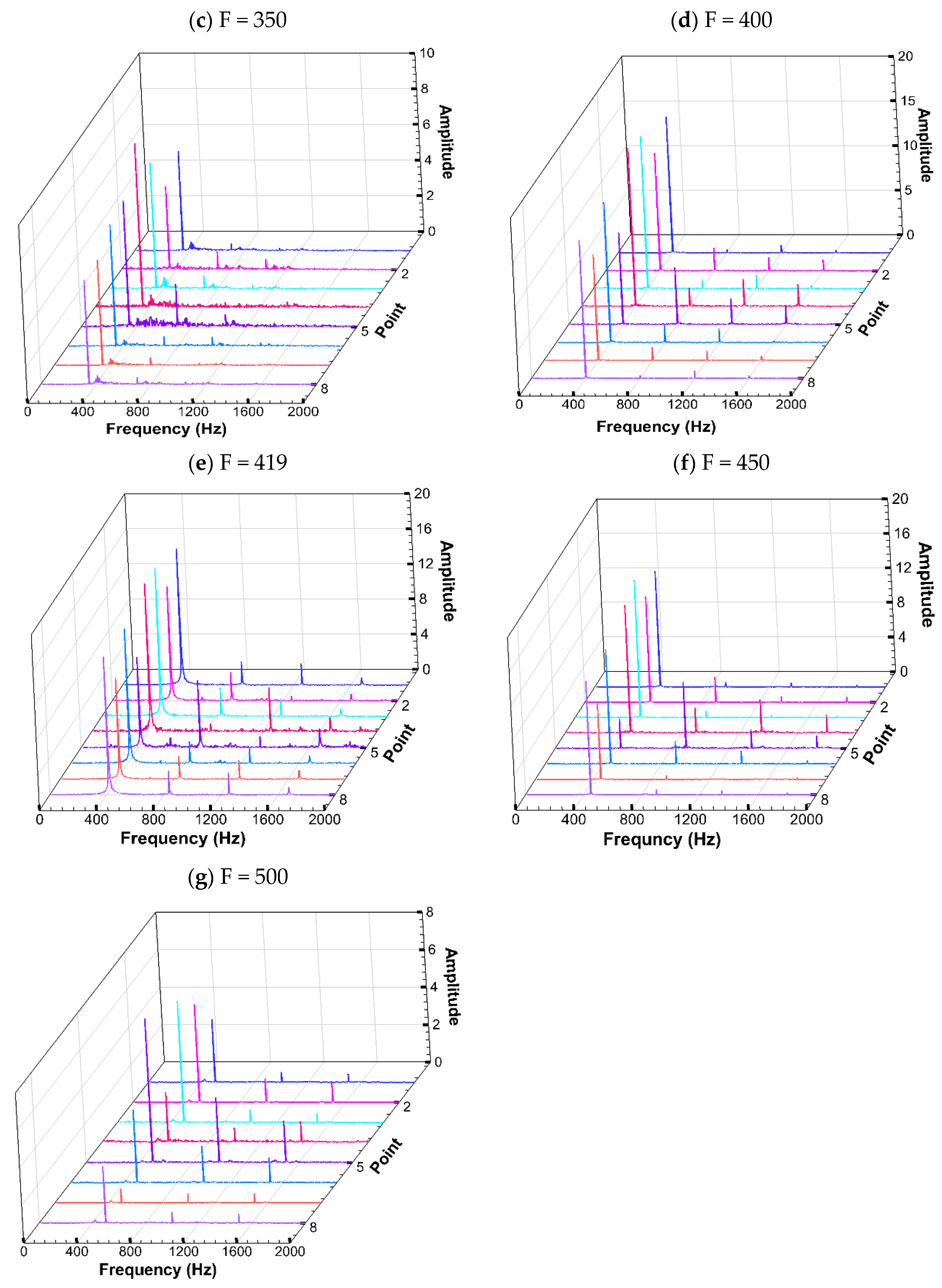
Detached eddy simulation (DES) is performed to investigate the acoustic environment of obstacle vortex-driven flow field due to transient combustion. Pressure time histories are recorded at eight different locations of the chamber (as shown in Figure 5). Seven different cases of unsteady combustion due to inlet mass flux disturbance are studied. Periodic inlet mass flux disturbance frequency is taken from 0 Hz to 500 Hz. Inlet mass flux is calculated using 66.3 + 2.1   sin 2 π   f t ,   kg / ( m 2 · s ) [3]. This inlet condition is taken due to the periodic flow behavior. Fast Fourier transform (FFT) has been performed to obtain both flow frequencies and amplitudes. The pressure spectrum at eight different locations of the chamber for six different inlet disturbance and steady-state cases are plotted in Figure 7. Pressure oscillation amplitude peak inside the chamber is found to be 2% to 5% of the mean pressure value for cases in which inlet mass flux disturbance frequency is far away to the acoustic mode of the combustion chamber. Peak value occurs at the inlet mass flux disturbance frequency. The result is in good agreement with previous studies [3] wherein it is found that oscillation is a result of the forced inlet conditions. The results also depict that pressure oscillation excites if inlet disturbance frequency is close to the acoustic mode. Amplitude rises up to 18%, however, still occurs at the inlet mass flux disturbance frequency, as shown in Table 2.
Previously, Wang [3] noticed that when the inlet mass flux disturbance frequency is close to the first acoustic mode, a larger amplitude pressure oscillation is excited at the frequency between the inlet mass flux disturbance frequency and the first acoustic mode. Wang did not consider the effects of the inhibitor and his test case consists of a cylindrical combustion chamber and nozzle. His studies focused on transient combustion of solid fuel and the acoustic environment due to surface or parietal vortex shedding. The present study is motivated by a desire to investigate the transient combustion of solid fuel and the acoustic environment due to obstacle vortex shedding. Therefore, in the present study the inhibitor is considered inside the cylindrical combustion chamber. It is found that pressure oscillation always occurs at inlet mass flux disturbance frequency for present flow conditions and configuration and does not travel towards acoustic mode. However similar to Wang [3], a larger amplitude pressure oscillation is noticed when the inlet mass flux disturbance frequency is close to the first acoustic mode.
Data acquisition points 6, 7, and 8 lie on the axis of the nozzle. Point 6 and point 8 are at the throat and near the mass flux inlet, respectively. Point 7 is placed at the center of the inhibitor ring. The acoustic wave in the chamber behaves similar to the standing wave if the inlet mass disturbance frequency is close to the acoustic mode. The inlet mass disturbance energy increases the pressure oscillation amplitude near the antinode. Points 6 and 8 are close to the antinode of the first-order acoustic standing wave and hence amplitude at these points has increased a little more (up to ~16%) as compared to point 7 (up to ~12%) which is in between node and antinode. Points 1 and point 3 are located close to the wall and same axial location as points 8 and point 6. Larger amplitude of pressure oscillations similar to point 8 and point 6 are also noticed at these locations. It is therefore concluded that severe pressure oscillations occur close to the antinode no matter if it exists on the center line or near the wall.
Point 5 exists near the throat wall. A pressure oscillation peak up to 10% of mean pressure between 400 Hz to 500 Hz inlet disturbance frequency is observed at this location. Pressure oscillation peak remains at inlet mass flux disturbance frequency. The second mode forced oscillation peak greater than 5% of mean pressure between 400 Hz to 500 Hz inlet disturbance frequency is also observed at this location. Point 5 exists at the minimum diameter location and after that flow expansion starts. Maximum heat load and high-pressure gradients are generated at the throat. First and second mode forced oscillation frequencies may interact with chamber natural frequency and end with the throat as well as chamber failure. Results show that the throat must be strengthened if the forced oscillation first or second mode frequency is close to the chamber’s natural frequency.
Inlet disturbance has a greater effect on the acoustic environment of the combustion chamber. Constant inlet mass flux boundary conditions may provide over-simplified results. Solid fuel characteristics must be studied in a subscale combustion chamber and reliable inlet mass flux boundary conditions be used for precise CFD simulations.

4. Conclusions

The objective of this study is to investigate transient combustion and the acoustic environment inside a chamber having obstacle vortex shedding. Various inlet mass flux disturbance frequencies close to the first mode natural frequency are studied. The study concludes as follows:
  • Pressure oscillation amplitude peak inside the chamber is found to be 2 to 5 % of the mean pressure value for cases in which inlet mass flux disturbance frequency is far away from the acoustic mode of the combustion chamber.
  • The amplitude of pressure oscillation up to 18% and 5% of mean pressure are evident at the first and second mode of forced oscillation frequencies whenever the inlet mass flux disturbance frequency is close to the chamber’s natural frequency.
  • For a combustion chamber with obstacle vortex shedding, pressure oscillation always occurs at inlet mass flux disturbance frequency and does not move towards the chamber’s natural frequency.
  • Simulation of transient combustion shows that if the combustion frequency is close to the chamber’s modal frequency, then its amplitude increases greatly and creates an acute acoustic environment which also results in fuel savings.
  • To evade the harsh acoustic environment and to burn fuel disproportionately, the modification of the combustion process or chamber configuration represents an appropriate solution.
The present work will surely help to understand the acoustic environment inside a combustion chamber with obstacle vortex shedding. The current work supports the aerospace industry in constructing combustion chambers for future launch vehicles that do not suffer from vortex-driven combustion instability.

Author Contributions

Conceptualization, A.A.B.; data curation, A.A.B., K.H. and M.H.; writing—original draft preparation, A.A.B. and L.K.; writing—review and editing, A.A.B., K.H., S.F.S. and M.H.; supervision, A.A.B., K.H., S.F.S. and M.H. All authors have read and agreed to the published version of the manuscript.

Funding

This research received no external funding.

Institutional Review Board Statement

Not applicable.

Informed Consent Statement

Not applicable.

Data Availability Statement

Not applicable.

Conflicts of Interest

The authors declare no conflict of interest.

References

  1. Culick, F.E.; Kuentzmann, P. Unsteady Motions in Combustion Chambers for Propulsion Systems; NATO Research and Technology Organization Neuilly-Sur-Seine: Paris, France, 2006. [Google Scholar]
  2. Su, W.; Li, S.; Zhang, Q.; Li, J.; Ye, Q.; Wang, N. Influence of thermal inhibitor position and temperature on vortex-shedding-driven pressure oscillations. Chinese J. Aeronaut. 2013, 26, 544–553. [Google Scholar] [CrossRef] [Green Version]
  3. Wang, D.; Yang, Y.; Fan, W.; Li, X.; Gao, Y. Simulation of pressure oscillations in a combustion chamber under periodic inlet disturbances. Acta Astronaut. 2018, 152, 859–871. [Google Scholar] [CrossRef]
  4. Emelyanov, V.N.; Teterina, I.V.; Volkov, K.N.; Garkushev, A.U. Pressure oscillations and instability of working processes in the combustion chambers of solid rocket motors. Acta Astronaut. 2017, 135, 161–171. [Google Scholar] [CrossRef] [Green Version]
  5. Anthoine, J. Experimental and Numerical Study of Aeroacoustic Phenomena in Large Solid Propellant Boosters. Ph.D. Thesis, Université Libre de Bruxelles, Faculté des Sciences Appliquées, Brussels, Belgium, 2000. [Google Scholar]
  6. Wolf, P.; Balakrishnan, R.; Staffelbach, G.; Gicquel, L.Y.M.; Poinsot, T. Using les to study reacting flows and instabilities in annular combustion chambers. Flow Turbul. Combust. 2012, 88, 191–206. [Google Scholar] [CrossRef] [Green Version]
  7. Wang, Z.; Li, X.; Feng, Z.; Yang, Z. The role of precessing vortex core in two combustion regimes: Numerical simulation studies. J. Mech. Sci. Technol. 2019, 33, 433–446. [Google Scholar] [CrossRef]
  8. Hegde, U.; Reuter, D.; Zinn, B.; Daniel, B. Fluid mechanically coupled combustion instabilities in ramjet combustors. In Proceedings of the 25th AIAA Aerospace Sciences Meeting, Reno, NV, USA, 24–26 March 1987; p. 216. [Google Scholar]
  9. Zhao, D.; Lu, Z.; Zhao, H.; Li, X.Y.; Wang, B.; Liu, P. A review of active control approaches in stabilizing combustion systems in aerospace industry. Prog. Aerosp. Sci. 2018, 97, 35–60. [Google Scholar] [CrossRef]
  10. Flandro, G.; Jacobs, H. Vortex generated sound in cavities. In Proceedings of the Aeroacoustics Conference, Seattle, WA, USA, 15–17 October 1973; p. 1014. [Google Scholar]
  11. Chen, L.; Gao, Y.; Wang, D.; Zou, Q.; Zhang, S. Numerical simulation on acoustic mode and pressure-oscillation decay in finocyl- and axil-grain combustion chambers. Aerosp. Sci. Technol. 2020, 107, 106351. [Google Scholar] [CrossRef]
  12. Stella, F.; Paglia, F. Pressure oscillations in solid rocket motors: Numerical study. Aerosp. Sci. Technol. 2011, 15, 53–59. [Google Scholar] [CrossRef]
  13. Shu, P.; Sforzini, R.; Forster, W., Jr. Vortex shedding from solid rocket propellant inhibitors. In Proceedings of the 22nd Joint Propulsion Conference, Hunstville, AL, USA, 16–18 June 1986; p. 1418. [Google Scholar]
  14. Zhao, D.; Li, X.Y. A review of acoustic dampers applied to combustion chambers in aerospace industry. Prog. Aerosp. Sci. 2015, 74, 114–130. [Google Scholar] [CrossRef]
  15. Dotson, K.W.; Koshigoe, S.; Pace, K.K. Vortex shedding in a large solid rocket motor without inhibitors at the segment interfaces. J. Propuls. Power 1997, 13, 197–206. [Google Scholar] [CrossRef]
  16. Bernardini, M.; Cimini, M.; Stella, F.; Cavallini, E.; Di Mascio, A.; Neri, A.; Martelli, E. Large-eddy simulation of vortex shedding and pressure oscillations in solid rocket motors. AIAA J. 2020, 58, 5191–5201. [Google Scholar] [CrossRef]
  17. Anthoine, J.; Lema, M.R. Passive Control of Pressure Oscillations in Solid Rocket Motors: Cold-Flow Experiments. J. Propuls. Power 2009, 25, 792–800. [Google Scholar] [CrossRef]
  18. Wang, C.; Zhang, Y.; Li, Z.; Xu, A. Pressure fluctuation—vortex interaction in an ultra-low specific-speed centrifugal pump. J. Low Freq. Noise Vib. Act. Control. 2019, 38, 527–543. [Google Scholar] [CrossRef] [Green Version]
  19. Anthoine, J.; Buchlin, J. Effect of nozzle cavity on resonance in large SRM: Numerical simulations introduction. J. Propuls. Power 2003, 19, 374–384. [Google Scholar] [CrossRef]
  20. Jia, Y.; Wang, Y.; Zhang, Q.; Rong, H.; Liu, Y.; Xiao, B.; Guo, D.; Laghari, M.; Ruan, R. Gas-carrying enhances the combustion temperature of the biomass particles. Energy 2022, 239, 121956. [Google Scholar] [CrossRef]
  21. Saha, S.; Chakraborty, D. Computational fluid dynamics simulation of combustion instability in solid rocket motor: Implementation of pressure coupled response function. Def. Sci. J. 2016, 66, 216–221. [Google Scholar] [CrossRef] [Green Version]
  22. Zhang, Q.; Wang, N.F.; Li, J.W.; Su, W.X.; Zhang, Y. Effect of the head cavity on pressure oscillation suppression characteristics in large solid rocket motors. Sci. China Technol. Sci. 2015, 58, 1250–1262. [Google Scholar] [CrossRef]
  23. Katona, C.; Safta, C.; Frunzulica, F.; Goemasn, M. Numerical simulations of gaseous flames in combustion chamber applications. In Journal of Physics: Conference Series, Proceedings of the 9th International Conference on Mathematical Modeling in Physical Sciences (IC-MSQUARE), Tinos Island, Greece, 7–10 September 2020; IOP Publishing: Bristol, UK, 2021; Volume 1730, p. 012110. [Google Scholar]
  24. Constante-Amores, C.R.; Kahouadji, L.; Batchvarov, A.; Shin, S.; Chergui, J.; Juric, D.; Matar, O.K. Direct numerical simulations of transient turbulent jets: Vortex-interface interactions. J. Fluid Mech. 2021, 922, A6. [Google Scholar] [CrossRef]
  25. Malalasekera, W.; Versteeg, H.K. An Introduction to Computational Fluid Dynamics: The Finite Volume Method; Prentice Hall: Harlow, UK, 2007. [Google Scholar]
Figure 1. Internal geometry of the Ariane 5 solid rocket motor.
Energies 15 06079 g001
Figure 2. Cold flow test case description.
Energies 15 06079 g002
Figure 3. Grid around inhibitor and nozzle with an exploded view of meshes.
Energies 15 06079 g003
Figure 4. Boundary conditions used in present study.
Energies 15 06079 g004
Figure 5. Data acquisition points for cold flow test case.
Energies 15 06079 g005
Figure 6. Pressure Spectrum at (a) point 1 and (b) point 3.
Energies 15 06079 g006
Figure 7. Pressure spectrum with periodic inlet disturbance.
Energies 15 06079 g007aEnergies 15 06079 g007b
Table 1. Modal frequency comparison for steady state combustion.
ModeExperimentalDES
Point 1Point 3
1408412.6412.6
2874837.2837.2
3128512281228
4174416471647
Table 2. Pressure oscillation amplitudes (% of mean pressure).
Frequency (HZ)Location
12345678
01.30.781.82.21.31.21.11.3
3002.43.54.55.65.44.84.22.6
3505.54.67.09.27.06.85.95.8
40015.213.217.117.810.215.711.815.5
41915.513.016.816.910.315.311.615.7
45013.412.215.914.83.413.38.713.2
5003.35.26.42.67.63.80.763.0
Publisher’s Note: MDPI stays neutral with regard to jurisdictional claims in published maps and institutional affiliations.