
A Review of Thermally Activated Building Systems (TABS) as an Alternative for Improving the Indoor Environment of Buildings

 ,
,  , ,
, ,
Abstract
: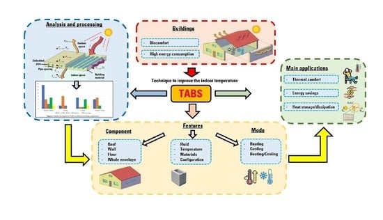
1. Introduction
2. TABS Embedded in Building Roofs
2.1. Potential of TABS to Improve Thermal Comfort When Installed in Roofs
2.2. Combination of TABS with Other Technologies for Roofs
2.3. Potential of TABS to Reduce the Energy Consumption When Installed in Roofs
3. TABS Embedded in Building Walls
3.1. Influence of the Flow Characteristics on the Thermal Behavior of TABS Embedded in Walls
3.2. Prediction of the Behavior of TABS Embedded in Walls
3.3. Heat Losses and Heat Dissipation of Walls Integrated with TABS
3.4. TABS Walls and Other Techniques for Energy Saving
4. TABS Embedded in Floor
4.1. Strategies for Improving the Behavior of TABS Embedded in Floors
4.2. Combination of TABS with Other Technologies for Floors
5. TABS Installed in Several Building Components
Indoor Temperature Behavior of Buildings with TABS Installed in Several Building Components
6. Results and Discussion
7. Conclusions
- TABS have not been analyzed from a structural mechanics point of view. From the knowledge of the authors, there are not yet studies that have considered the effect of the embedded pipes on the mechanical behavior of building components such as roofs and walls. This fact is crucial in roofs because of its role in a building; researchers should find the maximum diameter of the pipes and the optimal separation between them that does not affect the structural behavior of the roof.
- The thermal behavior of building components with TABS depends on many parameters; some of these parameters are: (a) type of building component, (b) orientation of the building wall; (b) type of arrangement of the pipes; (c) separation between the pipes or pipe spacing; (d) diameter of the pipes; (e) material of the pipes; (f) thermophysical properties of the fluid that circulates within the pipes; and (g) volumetric or mass flow rate of the fluid. Thus, optimization methods such as genetic algorithms or other artificial intelligence techniques should be used to find the optimum value for the parameters involved in a good design of TABS embedded in building components.
- Regarding the type of arrangement of the pipes, TABS in series or in a serpentine-type arrangement have been extensively studied. However, other types of pipe arrangement, such as parallel, mixed or even tree-shaped, should be explored to find the best arrangement that benefits the thermal performance of TABS for each application.
- The effect of fins on the thermal performance of TABS embedded in building components needs further development. Few studies have analyzed this measure when TABS are installed on building floors; the results show that the system with fins improves the thermal storage capacity compared with the traditional system.
- A building component with embedded TABS designed for heating is expected to have a material in the exterior layer with a high solar absorptance. On the contrary, a component with embedded TABS designed for cooling is expected to have a material in the exterior layer with a low solar absorptance. However, when the building component performs both heating and cooling, a layer with a suitable value of solar absorptance should be selected. Future studies on finding the optimal value of solar absorptance should be performed to improve the efficiency of TABS.
- The coupling of TABS with other systems that contribute to improve the thermal behavior of a building, such as green roofs and walls, and ventilated roofs and walls, has not been explored. These passive techniques could help to improve the thermal behavior of TABS.
Author Contributions
Funding
Institutional Review Board Statement
Informed Consent Statement
Data Availability Statement
Acknowledgments
Conflicts of Interest
Nomenclature
| C | Cooling |
| CO | Carbon dioxide |
| DPB | Distance between pipes (m) |
| F | Fluid |
| H | Heating |
| Mass flow rate (kg ) | |
| Volumetric flow rate () | |
| v | Fluid velocity (m ) |
| Abbreviations | |
| AHUs | Air handling units |
| AS | All-surface cooled TABS |
| Bio-PCM | Bio-based phase change material |
| CFD | Computational fluid dynamics |
| CLPHP | Closed-loop pulsating heat pipe |
| FD | Finite difference |
| FDFD | Frequency-domain finite difference |
| FEA | Finite element analysis |
| FVM | Finite volume method |
| GSHP | Ground source heat pump |
| HVAC | Heating, ventilation and air conditioning |
| IPCC | Intergovernmental Panel on Climate Change |
| MPC | Model predictive control |
| NTU | Numbers of transfer units method |
| PAC | Air conditioning system package |
| PCM | Phase change material |
| PE-RT | Polyethylene of raised temperature |
| PE-Xa | Cross-linked polyethylene |
| PMV | Predicted mean vote |
| PPD | Predicted percentage of dissatisfied |
| ppm | Parts per million |
| PPW | Parallel pipe-embedded wall |
| RC | Resistance–capacitance method |
| RF | Floor and roof cooled TABS |
| RFC | Radiant floor cooling |
| RFCAFC | Radiant floor and fan coil cooling |
| RFCUV | Radiant floor cooling with underfloor ventilation system |
| RFHS | Radiant floor heating system |
| SPW | Serial pipe-embedded wall |
| TABS | Thermally activated building system |
| TAGFRG | Gypsum roof reinforced with fiberglass |
| TAPCW | Thermo-activated PCM composite wall |
| TAW | Thermally activated wall system |
| TPTL | Two-phase thermosyphon loop |
| VRSP | Ventilated roof model with embedded pipes and a stabilized |
| layer of PCM | |
| WIPH | Wall implanted with heat pipes |
| XPAP | Aluminum–plastic pipe |
| Greek Symbols | |
| Diameter of the pipes (m) |
References
- IPCC. Climate Change 2014: Synthesis Report. Contribution of Working Groups I, II and III to the Fifth Assessment Report of the Intergovernmental Panel on Climate Change; IPCC: Geneva, Switzerland, 2014; 151p, Available online: https://www.ipcc.ch/report/ar5/syr/ (accessed on 30 July 2022).
- IEA. Global Status Report for Buildings and Construction: Towards a Zero-Emissions, Efficient and Resilient Buildings and Construction Sector; IEA: Paris, France, 2019; Available online: https://www.iea.org/reports/global-status-report-for-buildings-and-construction-2019 (accessed on 30 July 2022).
- Tong, S.; Li, H. An efficient model development and experimental study for the heat transfer in naturally ventilated inclined roofs. Build. Environ. 2014, 81, 296–308. [Google Scholar] [CrossRef]
- Ozarisoy, B. Energy effectiveness of passive cooling design strategies to reduce the impact of long-term heatwaves on occupants’ thermal comfort in Europe: Climate change and mitigation. J. Clean. Prod. 2022, 330, 129675. [Google Scholar] [CrossRef]
- Haghighi, A.; Maerefat, M. Design guideline for application of earth-to-air heat exchanger coupled with solar chimney as a natural heating system. Int. J. Low-Carbon Technol. 2015, 10, 294–304. [Google Scholar] [CrossRef]
- Peñaloza Peña, S.A.; Jaramillo Ibarra, J.E. Potential Applicability of Earth to Air Heat Exchanger for Cooling in a Colombian Tropical Weather. Buildings 2021, 11, 219. [Google Scholar] [CrossRef]
- Michalak, P. Impact of Air Density Variation on a Simulated Earth-to-Air Heat Exchanger’s Performance. Energies 2022, 15, 3215. [Google Scholar] [CrossRef]
- Kharrufa, S.N.; Adil, Y. Upgrading the building envelope to reduce cooling loads. Energy Build. 2012, 55, 389–396. [Google Scholar] [CrossRef]
- Bunkholt, N.S.; Säwén, T.; Stockhaus, M.; Kvande, T.; Gullbrekken, L.; Wahlgren, P.; Lohne, J. Experimental Study of Thermal Buoyancy in the Cavity of Ventilated Roofs. Buildings 2020, 10, 8. [Google Scholar] [CrossRef]
- Lee, H.; Ozaki, A.; Choi, Y.; Iqbal, M. Performance Improvement Plan of Air Circulation-Type Solar Heat-Storage System Using Ventilated Cavity of Roof. Energies 2021, 14, 1606. [Google Scholar] [CrossRef]
- Silva, C.M.; Gomes, M.G.; Silva, M. Green roofs energy performance in Mediterranean climate. Energy Build. 2016, 116, 318–325. [Google Scholar] [CrossRef]
- Zingre, K.T.; Kumar Devs, K.; Wan, M.P. Analysing the Effect of Substrate Properties on Building Envelope Thermal Performance in Various Climates. Energies 2020, 13, 5119. [Google Scholar] [CrossRef]
- Barozzi, B.; Pollastro, M.C. Assessment of the Impact of Cool Roofs in Temperate Climates through a Comparative Experimental Campaign in Outdoor Test Cells. Buildings 2016, 6, 52. [Google Scholar] [CrossRef]
- Ozarisoy, B.; Altan, H. A novel methodological framework for the optimisation of post-war social housing developments in the South-eastern Mediterranean climate: Policy design and life-cycle cost impact analysis of retrofitting strategies. Sol. Energy 2021, 225, 517–560. [Google Scholar] [CrossRef]
- Suárez, R.; Escandón, R.; López-Pérez, R.; León-Rodríguez, L.; Klein, T.; Silvester, S. Impact of Climate Change: Environmental Assessment of Passive Solutions in a Single-Family Home in Southern Spain. Sustainability 2018, 10, 2914. [Google Scholar] [CrossRef]
- Bugenings, L.A.; Kamari, A. Bioclimatic Architecture Strategies in Denmark: A Review of Current and Future Directions. Buildings 2022, 12, 224. [Google Scholar] [CrossRef]
- Romaní Picas, J.; Pérez Luque, G.; Gracia Cuesta, A.D. Experimental evaluation of a heating radiant wall coupled to a ground source heat pump. Renew. Energy 2017, 105, 520–529. [Google Scholar] [CrossRef]
- Michalak, P. Selected Aspects of Indoor Climate in a Passive Office Building with a Thermally Activated Building System: A Case Study from Poland. Energies 2021, 14, 860. [Google Scholar] [CrossRef]
- Almeida, R.M.S.F.; Vicente, R.d.S.; Ventura-Gouveia, A.; Figueiredo, A.; Rebelo, F.; Roque, E.; Ferreira, V.M. Experimental and Numerical Simulation of a Radiant Floor System: The Impact of Different Screed Mortars and Floor Finishings. Materials 2022, 15, 1015. [Google Scholar] [CrossRef]
- Romaní Picas, J.; Cabeza, L.F.; Pérez Luque, G.; Pisello, A.L.; Gracia Cuesta, A.D. Experimental testing of cooling internal loads with a radiant wall. Renew. Energy 2018, 116, 1–8. [Google Scholar] [CrossRef]
- Resources, E.D. Radiant Cooling, Energy Design Resources: Building Envelope Design; Financial Times Energy, Inc.: Boulder, CO, USA, 2003. [Google Scholar]
- Ma, P.; Wang, L.S.; Guo, N. Modeling of TABS-based thermally manageable buildings in Simulink. Appl. Energy 2013, 104, 791–800. [Google Scholar] [CrossRef]
- Rhee, K.N.; Kim, K.W. A 50 year review of basic and applied research in radiant heating and cooling systems for the built environment. Build. Environ. 2015, 91, 166–190. [Google Scholar] [CrossRef]
- Romaní Picas, J.; Gracia Cuesta, A.D.; Cabeza, L.F. Simulation and control of thermally activated building systems (TABS). Energy Build. 2016, 127, 22–42. [Google Scholar] [CrossRef]
- Ma, P.; Wang, L.S.; Guo, N. Energy storage and heat extraction—From thermally activated building systems (TABS) to thermally homeostatic buildings. Renew. Sustain. Energy Rev. 2015, 45, 677–685. [Google Scholar] [CrossRef]
- Krajčík, M.; Šikula, O. The possibilities and limitations of using radiant wall cooling in new and retrofitted existing buildings. Appl. Therm. Eng. 2020, 164, 114490. [Google Scholar] [CrossRef]
- Krajčík, M.; Arıcı, M.; Šikula, O.; Šimko, M. Review of water-based wall systems: Heating, cooling, and thermal barriers. Energy Build. 2021, 253, 111476. [Google Scholar] [CrossRef]
- Cai, R.; Sun, Z.; Yu, H.; Meng, E.; Wang, J.; Dai, M. Review on optimization of phase change parameters in phase change material building envelopes. J. Build. Eng. 2021, 35, 101979. [Google Scholar] [CrossRef]
- Dong, W.; Chen, Y.; Bao, Y.; Fang, A. A validation of dynamic hygrothermal model with coupled heat and moisture transfer in porous building materials and envelopes. J. Build. Eng. 2020, 32, 101484. [Google Scholar] [CrossRef]
- Wei, M.; Wang, B.; Liu, S. Numerical Simulation of Heat and Moisture Transfer of Wall with Insulation. J. Phys. Conf. Ser. 2019, 1300, 012029. [Google Scholar] [CrossRef]
- Gwerder, M.; Lehmann, B.; Tödtli, J.; Dorer, V.; Renggli, F. Control of thermally-activated building systems (TABS). Appl. Energy 2008, 85, 565–581. [Google Scholar] [CrossRef]
- De Wit, A.; Wisse, C. Hydronic circuit topologies for thermally activated building systems-design questions and case study. Energy Build. 2012, 52, 56–67. [Google Scholar] [CrossRef]
- Rey Martínez, F.J.; Chicote, M.A.; Peñalver, A.V.; Gónzalez, A.T.; Gómez, E.V. Indoor air quality and thermal comfort evaluation in a Spanish modern low-energy office with thermally activated building systems. Sci. Technol. Built Environ. 2015, 21, 1091–1099. [Google Scholar] [CrossRef]
- Chung, W.J.; Park, S.H.; Yeo, M.S.; Kim, K.W. Control of thermally activated building system considering zone load characteristics. Sustainability 2017, 9, 586. [Google Scholar] [CrossRef]
- Dharmasastha, K.; Samuel, D.L.; Nagendra, S.S.; Maiya, M. Experimental investigation of thermally activated glass fibre reinforced gypsum roof. Energy Build. 2020, 228, 110424. [Google Scholar] [CrossRef]
- Saw, L.; Yew, M.; Yew, M.; Chong, W.; Poon, H.; Liew, W.; Yeo, W. Development of the closed loop pulsating heat pipe cool roof system for residential buildings. Case Stud. Therm. Eng. 2021, 28, 101487. [Google Scholar] [CrossRef]
- Wu, M.; Liu, X.; Tang, H. Simulation Analysis on the Solar Heating System Combined with Tabs in Lhasa, China of Annex 59. Energy Proc. 2015, 78, 2439–2444. [Google Scholar] [CrossRef]
- Chung, W.J.; Park, S.H. Utilization of Thermally Activated Building System with Horizontal Ground Heat Exchanger Considering the Weather Conditions. Energies 2021, 14, 7927. [Google Scholar] [CrossRef]
- Yu, J.; Yang, Q.; Ye, H.; Huang, J.; Liu, Y.; Tao, J. The optimum phase transition temperature for building roof with outer layer PCM in different climate regions of China. Energy Procedia 2019, 158, 3045–3051. [Google Scholar] [CrossRef]
- Yu, J.; Leng, K.; Ye, H.; Xu, X.; Luo, Y.; Wang, J.; Yang, X.; Yang, Q.; Gang, W. Study on thermal insulation characteristics and optimized design of pipe-embedded ventilation roof with outer-layer shape-stabilized PCM in different climate zones. Renew. Energy 2020, 147, 1609–1622. [Google Scholar] [CrossRef]
- Heidenthaler, D.; Leeb, M.; Schnabel, T.; Huber, H. Comparative analysis of thermally activated building systems in wooden and concrete structures regarding functionality and energy storage on a simulation-based approach. Energy 2021, 233, 121138. [Google Scholar] [CrossRef]
- Hu, R.; Li, X.; Liang, J.; Wang, H.; Liu, G. Field study on cooling performance of a heat recovery ground source heat pump system coupled with thermally activated building systems (TABS). Energy Convers. Manag. 2022, 262, 115678. [Google Scholar] [CrossRef]
- Lehmann, B.; Dorer, V.; Koschenz, M. Application range of thermally activated building systems tabs. Energy Build. 2007, 39, 593–598. [Google Scholar] [CrossRef]
- Zhu, L.; Yang, Y.; Chen, S.; Sun, Y. Thermal performances study on a façade-built-in two-phase thermosyphon loop for passive thermo-activated building system. Energy Convers. Manag. 2019, 199, 112059. [Google Scholar] [CrossRef]
- Romaní, J.; Cabeza, L.F.; de Gracía, A. Development and experimental validation of a transient 2D numeric model for radiant walls. Renew. Energy 2018, 115, 859–870. [Google Scholar] [CrossRef]
- Todorović, R.I.; Banjac, M.J.; Vasiljević, B.M. Analytical and experimental determination of the temperature field on the surface of wall heating panels. Therm. Sci. 2015, 19, 497–507. [Google Scholar] [CrossRef]
- Xie, J.; Xu, X.; Li, A.; Zhu, Q. Experimental validation of frequency-domain finite-difference model of active pipe-embedded building envelope in time domain by using Fourier series analysis. Energy Build. 2015, 99, 177–188. [Google Scholar] [CrossRef]
- Zhu, Q.; Xu, X.; Gao, J.; Xiao, F. A semi-Dynamic simplified therm model of active pipe embedded building envelope based on frequency finite difference method. Int. J. Therm. Sci. 2015, 88, 170–179. [Google Scholar] [CrossRef]
- Zhu, Q.; Li, A.; Xie, J.; Li, W.; Xu, X. Experimental validation of a semi-dynamic simplified model of active pipe-embedded building envelope. Int. J. Therm. Sci. 2016, 108, 70–80. [Google Scholar] [CrossRef]
- Ibrahim, M.; Wurtz, E.; Anger, J.; Ibrahim, O. Experimental and numerical study on a novel low temperature façade solar thermal collector to decrease the heating demands: A south–north pipe-embedded closed-water-loop system. Sol. Energy 2017, 147, 22–36. [Google Scholar] [CrossRef]
- Qu, S.; Hu, W.; Yuan, S.; Yin, R.; Ji, R. Optimal design and operation of thermally activated wall in the ultra-low energy buildings in China. Buil. Simul. 2020, 13, 961–975. [Google Scholar] [CrossRef]
- Jiang, S.; Li, X.; Lyu, W.; Wang, B.; Shi, W. Numerical investigation of the energy efficiency of a serial pipe-embedded external wall system considering water temperature changes in the pipeline. J. Build. Eng. 2020, 31, 101435. [Google Scholar] [CrossRef]
- Li, Z.; Zhang, Z. Dynamic heat transfer characteristics of wall implanted with heat pipes in summer. Energy Build. 2018, 170, 40–46. [Google Scholar] [CrossRef]
- Iffa, E.; Hun, D.; Salonvaara, M.; Shrestha, S.; Lapsa, M. Performance evaluation of a dynamic wall integrated with active insulation and thermal energy storage systems. J. Energy Storage 2022, 46, 103815. [Google Scholar] [CrossRef]
- Krzaczek, M.; Florczuk, J.; Tejchman, J. Improved energy management technique in pipe-embedded wall heating/cooling system in residential buildings. Appl. Energy 2019, 254, 113711. [Google Scholar] [CrossRef]
- Stojanović, B.V.; Janevski, J.N.; Mitković, P.B.; Stojanović, M.B.; Ignjatović, M.G. Thermally activated building systems in context of increasing building energy efficiency. Therm. Sci. 2014, 18, 1011–1018. [Google Scholar] [CrossRef]
- Guerrero Delgado, M.C.; Sánchez, J.; Álvarez, S.; Tenorio Ríos, J.A.; Cabeza, L.F.; Bartolomé, C.; Pavón Moreno, M.C. Evaluation of the behavior of an innovative thermally activated building system (TABS) with PCM for an efficient design. E3S Web Conf. 2019, 111, 8. [Google Scholar]
- Chen, S.; Yang, Y.; Olomi, C.; Zhu, L. Numerical study on the winter thermal performance and energy saving potential of thermo-activated PCM composite wall in existing buildings. Buil. Simul. 2020, 13, 237–256. [Google Scholar] [CrossRef]
- Delgado, M.G.; Ramos, J.S.; Domínguez, S.; Ríos, J.A.T.; Cabeza, L.F. Building thermal storage technology: Compensating renewable energy fluctuations. J. Energy Storage 2020, 27, 101147. [Google Scholar] [CrossRef]
- Kisilewicz, T.; Fedorczak-Cisak, M.; Barkanyi, T. Active thermal insulation as an element limiting heat loss through external walls. Energy Build. 2019, 205, 109541. [Google Scholar] [CrossRef]
- Qu, S.; Su, S.; Li, H.; Hu, W. Optimized control of the supply water temperature in the thermally activated building system for cold climate in China. Sustain. Cities Soc. 2019, 51, 101742. [Google Scholar] [CrossRef]
- Kalús, D.; Gašparík, J.; Janík, P.; Kubica, M.; Št’astnỳ, P. Innovative Building Technology Implemented into Facades with Active Thermal Protection. Sustainability 2021, 13, 4438. [Google Scholar] [CrossRef]
- Arroyo, J.; Spiessens, F.; Helsen, L. Comparison of Model Complexities in Optimal Control Tested in a Real Thermally Activated Building System. Buildings 2022, 12, 539. [Google Scholar] [CrossRef]
- Joe, J.; Karava, P. A model predictive control strategy to optimize the performance of radiant floor heating and cooling systems in office buildings. Appl. Energy 2019, 245, 65–77. [Google Scholar] [CrossRef]
- Feng, J.D.; Schiavon, S.; Bauman, F. New method for the design of radiant floor cooling systems with solar radiation. Energy Build. 2016, 125, 9–18. [Google Scholar] [CrossRef]
- Yang, X.; Pan, L.; Guan, W.; Tian, Z.; Wang, J.; Zhang, C. Optimization of the configuration and flexible operation of the pipe-embedded floor heating with low-temperature district heating. Energy Build. 2022, 269, 112245. [Google Scholar] [CrossRef]
- Ma, J.; Yang, Y.; Zheng, X.; Dai, B.; Zhu, D.; Liu, Q. Impact on heat storage performance of concrete radiant floor with finned water supply pipes. J. Build. Eng. 2021, 44, 103351. [Google Scholar] [CrossRef]
- Ruiz-Pardo, Á.; Rodríguez Jara, E.Á.; Conde García, M.; Ríos, J.A.T. Influence of Wood Properties and Building Construction on Energy Demand, Thermal Comfort and Start-Up Lag Time of Radiant Floor Heating Systems. Appl. Sci. 2022, 12, 2335. [Google Scholar] [CrossRef]
- Park, S.H.; Chung, W.J.; Yeo, M.S.; Kim, K.W. Evaluation of the thermal performance of a Thermally Activated Building System (TABS) according to the thermal load in a residential building. Energy Build. 2014, 73, 69–82. [Google Scholar] [CrossRef]
- Cen, C.; Jia, Y.; Liu, K.; Geng, R. Experimental comparison of thermal comfort during cooling with a fan coil system and radiant floor system at varying space heights. Build. Environ. 2018, 141, 71–79. [Google Scholar] [CrossRef]
- Zhang, D.; Cai, N.; Cui, X.; Xia, X.; Shi, J.; Huang, X. Experimental investigation on model predictive control of radiant floor cooling combined with underfloor ventilation system. Energy 2019, 176, 23–33. [Google Scholar] [CrossRef]
- Gu, X.; Cheng, M.; Zhang, X.; Qi, Z.; Liu, J.; Li, Z. Performance analysis of a hybrid non-centralized radiant floor cooling system in hot and humid regions. Case Stud. Therm. Eng. 2021, 28, 101645. [Google Scholar] [CrossRef]
- Hwang, Y.J.; Jeong, J.W. Energy Saving Potential of Radiant Floor Heating Assisted by an Air Source Heat Pump in Residential Buildings. Energies 2021, 14, 1321. [Google Scholar] [CrossRef]
- Sharifi, M.; Mahmoud, R.; Himpe, E.; Laverge, J. A heuristic algorithm for optimal load splitting in hybrid thermally activated building systems. J. Build. Eng. 2022, 50, 104160. [Google Scholar] [CrossRef]
- Zhu, X.; Liu, J.; Zhu, X.; Wang, X.; Du, Y.; Miao, J. Experimental Study on Operating Characteristic of a Combined Radiant Floor and Fan Coil Cooling System in a High Humidity Environment. Buildings 2022, 12, 499. [Google Scholar] [CrossRef]
- Ren, J.; Liu, J.; Zhou, S.; Kim, M.K.; Song, S. Experimental study on control strategies of radiant floor cooling system with direct-ground cooling source and displacement ventilation system: A case study in an office building. Energy 2022, 239, 122410. [Google Scholar] [CrossRef]
- Khan, Y.; Khare, V.R.; Mathur, J.; Bhandari, M. Performance evaluation of radiant cooling system integrated with air system under different operational strategies. Energy Build. 2015, 97, 118–128. [Google Scholar] [CrossRef]
- DG, L.S.; Nagendra, S.S.; Maiya, M. Feasibility analysis of passive thermally activated building system for various climatic regions in India. Energy Build. 2017, 155, 352–363. [Google Scholar]
- Leo Samuel, D.; Nagendra, S.S.; Maiya, M. Simulation of indoor comfort level in a building cooled by a cooling tower–concrete core cooling system under hot–semiarid climatic conditions. Indoor Built Environ. 2017, 26, 680–693. [Google Scholar] [CrossRef]
- Samuel, D.L.; Nagendra, S.S.; Maiya, M.P. Parametric analysis on the thermal comfort of a cooling tower based thermally activated building system in tropical climate–An experimental study. Appl. Therm. Eng. 2018, 138, 325–335. [Google Scholar] [CrossRef]
- Leo Samuel, D.; Shiva Nagendra, S.; Maiya, M. An analysis of operating parameters in the cooling tower-based thermally activated building system. Indoor Built Environ. 2018, 27, 1175–1186. [Google Scholar] [CrossRef]
- Leo Samuel, D.; Shiva Nagendra, S.; Maiya, M. A study of pipe parameters on the performance of cooling tower-based thermally activated building system. Indoor Built Environ. 2018, 27, 219–232. [Google Scholar] [CrossRef]
- Samuel, D.L.; Nagendra, S.S.; Maiya, M. A sensitivity analysis of the design parameters for thermal comfort of thermally activated building system. Sādhanā 2019, 44, 48. [Google Scholar] [CrossRef]
- Dharmasastha, K.; Leo Samuel, D.; Shiva Nagendra, S.; Maiya, M. Thermal comfort of a radiant cooling system in glass fiber reinforced gypsum roof-an experimental study. Appl. Therm. Eng. 2022, 214, 118842. [Google Scholar] [CrossRef]
- Montenegro López, F.J.; Hongn, M.E. Estudio computacional de un sistema de acumulación estructural orientado a refrescamiento bioclimático: Primeros resultados. Av. Energías Renov. Medio Ambiente 2020, 24, 51–61. [Google Scholar]
- Oravec, J.; Šikula, O.; Krajčík, M.; Arıcı, M.; Mohapl, M. A comparative study on the applicability of six radiant floor, wall, and ceiling heating systems based on thermal performance analysis. J. Build. Eng. 2021, 36, 102133. [Google Scholar] [CrossRef]


| Name | Location | Mode |
|---|---|---|
|
|
|
| Reference | Weather | Mode * | TABS Features * | Model | Findings |
|---|---|---|---|---|---|
| [31] | - | H, C | F = Water, DBP = 0.2 m, = 0.015 m |  | The thermal comfort can be maintained between 21 and 27 °C if TABS are used with intermittent operation. |
| [32] | Temperate | H, C | F = Water | - | TABS maintained the indoor air temperature within 80–90% of comfort satisfaction zone. |
| [33] | - | C | F = Water | - | TABS maintained the indoor air temperature in a range between 23 and 25 °C. |
| [34] | - | H, C | F = Water |  | A control strategy by zones improves the thermal comfort by 5% with the TABS installed in the roof. |
| [35] | Warm and humid | C | F = Water, DBP = 0.054 m, = 0.01 m |  | TABS decreased the indoor air temperature of the test chamber by up to 6.7 °C. |
| [36] | Tropical | C | F = Methanol, = 0.00635 m |  | A CLPHP coupled to a metal roof reduced the indoor air temperature by up to 13% compared with the bare metal roof system. |
| Reference | Weather | Mode * | TABS Features * | Model | Combination |
|---|---|---|---|---|---|
| [37] | Cold region | H | F = Air, DBP = 0.12 m, = 0.04 m, v = 2 m s |  | Solar air collector and TABS |
| [38] | Equatorial, arid, warm temperature, snow, polar | H, C | - |  | Horizontal ground heat exchanger and TABS |
| [39] | Cool, winter, hot summer, mild regions | - | F = Air, DBP = 0.024 m, = 0.08 m |  | PCM and TABS |
| [40] | - | - | F = Air, DBP = 0.024 m, = 0.08 m |  | PCM and TABS |
| [41] | - | H | F = Water, DBP= 0.15 m, = 0.016 m |  | Wood and TABS |
| [42] | Cold winter | H, C | F = Water |  | GSHP with TABS. |
| Reference | Mode * | TABS Features * | Model | Findings |
|---|---|---|---|---|
| [34] | H, C | F = Water |  | The heating load was reduced by 10%, the cooling load was reduced 36%, and total energy consumption decreased by 13% with the TABS. |
| [43] | C | F = Water, DBP = 0.25 m, = 0.020 m, = 13 kg h | - | The TABS reduced the energy consumption by 50% in cooling mode. |
| Reference | Mode * | TABS Features * | Model | Findings |
|---|---|---|---|---|
| [44] | H | F = Ethanol, DPB = 0.20 m, = 0.00822 m |  | The system exchanges 25.5 W m with the internal surface of the wall |
| [45] | - | F = Water, DPB = 0.05–0.30, = 0.016 m |  | The temperature difference between the inner and outer surface of the wall decreases by up to 20 °C |
| Reference | Mode * | TABS Features * | Model | Simulation Method/Model | Simulation Tool |
|---|---|---|---|---|---|
| [45] | - | F = Water, DPB = 0.05–0.30, = 0.016 m |  | FVM | - |
| [46] | H | F = Water, DBP = 0.07 and 0.10 m, = 0.016 m and 0.0116 m, = 2 L h, |  | Faxen-Rydberg-Huber | - |
| [47] | H, C | F = Water, DBP = 0.20 m, = 0.020 m, v = 0.5 m s |  | FDFD | FLUENT |
| [48] | - | F= Water, DBP = 0.20 m, = 0.02 m, v = 0.5–0.7 m s |  | RC-NTU | Program written in FORTRAN Code |
| [49] | H, C | F = Water, DBP = 0.20 m, = 0.02 m, v = 0.8–0.5 m s |  | RC-NTU | - |
| [50] | H | F= Water, antifreeze, DPB = 0.10 m, = 0.012 m, = 5.3–116 L h |  | - | TRNSYS |
| [51] | H, C | F = Water, DPB= 0.10, 0.20, and 0.30 m, = 0.02 m, v = 0.2 m s |  | FEM | COMSOL |
| [52] | H, C | F = Water, DPB = 0.08 m, = 0.008 m, v = 2.7 m s |  | FVM | FLUENT |
| Reference | Mode * | TABS Features * | Model | Findings |
|---|---|---|---|---|
| [50] | H | F = Water, antifreeze, DPB = 0.10 m, = 0.012 m, = 5.3–116 L h |  | With the system proposed the heat losses were reduced from 35% to 9%. |
| [53] | C | = 0.0042 m |  | The system has a heat transfer capacity of 50.7 kW m. The temperature of the wall with TABS was 2 °C lower than a conventional wall. |
| [54] | H | F = Water, DPB = 0.076–0.152 m, = 0.019 m |  | The TABS reduced the temperature of the wall by 10 °C. |
| [55] | H, C | F = Water, DPB = 0.20 m, = 0.025 m, |  | The control method through the thermal barrier system was able to maintain a comfortable temperature inside, with a temperature variation smaller than 1 °C. |
| Reference | Mode * | TABS Features * | Model | Findings |
|---|---|---|---|---|
| [52] | H, C | F = Water, DPB = 0.08 m, = 0.008 m, v = 2.7 m s |  | A serial pipe-embedded wall reduced energy load rate by 25.2% while a wall with embedded tubes connected in parallel reduced it by 8.7%. |
| [56] | H | F = Water |  | When the TABS is adapted for heating a home, it can provide energy savings of up to 75%. |
| [57] | H | F = Water, DPB = 0.08, 0.10, 0.12 m, = 0.01 m, v = 2.7 m s |  | The efficiency of the TABS increases by up to 7% when the inlet temperature increases, and when increasing the distance between the pipes it decreases by up to 6%. |
| [58] | H | F = Water, DPB = 0.15 m, = 0.02 m |  | The thermo-activated PCM composite wall increased the indoor temperature and reduced energy consumption by 65%. |
| [59] | H | F = Water, DPB = 0.10 m, = 0.01 m, v = 1–2 m s |  | The TABS provided energy savings of up to 40% in heating mode. |
| [60] | H, C | F = Refrigerant, Water, DPB = 0.2 m, = 0.02 m |  | TABS improves the exterior wall’s insulation parameters because it causes a reduction in total energy loss from 53 to 81%. |
| [61] | H, C | F = Water, DPB = 0.15 m, = 0.014 m |  | The proposed system reduced the discomfort rate by over 35%. |
| [62] | H, C | - |  | The proposed panel application is most suitable for buildings made with materials with good thermal conductivity and heat accumulation. |
| Reference | Mode * | TABS Features * | Model | Findings |
|---|---|---|---|---|
| [64] | H, C | F = Water |  | When applying the MPC, the indoor temperature was 22–26 °C for the cooling mode and 17–25 °C for the heating mode. Soil temperature was maintained in a range of 15 to 29 °C. |
| [65] | C | F = Water |  | The radiant floor increased its cooling capacity up to 140 W m. |
| [66] | H | F = Water, DBP = 0.1–0.5 m, = 0.026 m |  | A tube spacing of 0.3 m maintained a comfort temperature of 21 to 25 °C |
| [67] | H | F = Water, DBP = 0.15 m, = 0.02 m |  | Implementing aluminum fins on the heat exchanger tubes improves the thermal behavior of a floor. Storage capacity increases with fin material embedded in exchanger tubes. |
| [68] | H | F = Water, DPB = 0.15 m, = 0.016 m, = 200 L h |  | By using the TABS on the floor, the energy demand decreased by 18% and thermal comfort increased by 14%. |
| Reference | Mode * | TABS Features * | Model | Findings |
|---|---|---|---|---|
| [69] | H, C | F = Water, DPB = 0.2 m, = 0.02 m |  | The indoor air temperature remained at 26 °C with a TABS and an air conditioning system. |
| [70] | C | F = Water |  | With a height of 5 m in a room, the radiant floor helps to improve thermal comfort, maintaining a temperature of 20.36 °C. |
| [71] | C | F = Water, DBP = 0.01 m, = 0.01 m |  | With the model predictive control, there is an energy saving of up to 17.5%, with an operating temperature of up to 24.5 °C. |
| [72] | C | F = Water, DBP = 0.05 m, = 0.01 m |  | With the coupling of the radiant floor + fan coil + air source heat pump, a comfort temperature of 24.6–26.4 °C can be achieved indoors. |
| [73] | H | F = Water |  | The radiant floor heating has a better performance when the floor temperature is 22 °C, providing an energy saving of 37.6%. |
| [74] | H, C | F = Water |  | TABS maintained the indoor air temperature between 21 and 26 °C. |
| [75] | C | F = Water, DBP = 0.06 m, = 0.012 m |  | With the RFCAFC, the indoor air temperature remained in the range of 25.4–26.6 °C. |
| [76] | C | F = Water |  | The interior temperature was maintained between 26 °C and 27 °C with the proposed system. |
| Reference | Weather | Mode * | TABS Features * | Model | Findings |
|---|---|---|---|---|---|
| [77] | - | C | F = Water, DPB = 0.10 and 0.15 m, = 0.015 m |  | The radiant cooling systems provided energy savings of up to 30% compared to a traditional system. |
| [78] | Semi-arid, arid, humid subtropical, tropical wet and dry, tropical wet | C | F = Water | 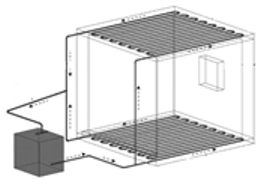 | The TABS in the roof reduced the operative temperature by 9.5 °C, while the TABS in all surfaces reduced it by 14.4 °C. |
| [79] | Hot semi-arid | C | F = Water, DPB = 0.20 m, = 0.024 m | | The system maintained indoor air temperature between 23.5 °C and 28 °C. |
| [80] | Hot semi-arid | C | F = Water, DPB = 0.02 m, = 0.00128 m | 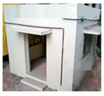 | The indoor air temperature was reduced by 1.6 °C when the separation between pipes was increased; 2.7 °C by moving the pipes to the interior surface direction; and 32.1 °C by changing the arrangement of the tubes from coil to parallel. |
| [81] | Hot and dry summer | C | F = Water, DPB = 0.2 m, = 0.013 m | 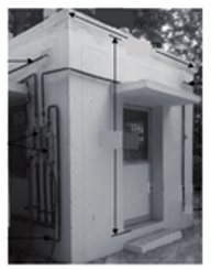 | The number of cooling surfaces was the parameter that had the most significant effect on thermal comfort. If all the room surfaces are cooled, the average indoor temperature is reduced by up to 5.7 °C. |
| [82] | Tropical wet, Dry climate | C | F = Water, DPB = 0.2 m, = 0.016 m | | When TABS cooling was activated only on the roof, the indoor temperature remained at 33.1 °C. Meanwhile, when the TABS cooling was activated on the entire envelope, the temperature decreased to 29.2 °C. |
| [83] | - | C | F = Water, DPB = 0.2 m, = 0.01 m, v = 0.4 m s | | Increasing the thermal conductivity of the pipes improves the system’s cooling performance. The system can reduced the indoor operating temperature by 4.7 °C. |
| [18] | - | H, C | F = Water |  | Implementing a TABS with mechanical ventilation systems improves the thermal comfort conditions in an enclosure. |
| [84] | Warm and humid | C | F = Water, DBP = 0.054 m, = 0.01 and 0.015 m |  | The TABS reduced the indoor air temperature by 2.1 °C when the temperature of the cooling water was reduced from 26 °C to 18 °C. |
| [85] | - | C | F = Water, = 8 L min |  | Heat removal in an enclosure increases when tube spacing and tube depth are decreased. The potential of a roof is higher (20–30%) compared to a floor TABS, with the same characteristics. |
| [86] | - | H | F = Water, DBP = 0.8–0.30 m, = 0.009–0.020 m |  | The thermal performance depends on the location of the tubes with respect to the indoor environment. |
Publisher’s Note: MDPI stays neutral with regard to jurisdictional claims in published maps and institutional affiliations. |
© 2022 by the authors. Licensee MDPI, Basel, Switzerland. This article is an open access article distributed under the terms and conditions of the Creative Commons Attribution (CC BY) license (https://creativecommons.org/licenses/by/4.0/).
Share and Cite
Villar-Ramos, M.M.; Hernández-Pérez, I.; Aguilar-Castro, K.M.; Zavala-Guillén, I.; Macias-Melo, E.V.; Hernández-López, I.; Serrano-Arellano, J. A Review of Thermally Activated Building Systems (TABS) as an Alternative for Improving the Indoor Environment of Buildings. Energies 2022, 15, 6179. https://doi.org/10.3390/en15176179
Villar-Ramos MM, Hernández-Pérez I, Aguilar-Castro KM, Zavala-Guillén I, Macias-Melo EV, Hernández-López I, Serrano-Arellano J. A Review of Thermally Activated Building Systems (TABS) as an Alternative for Improving the Indoor Environment of Buildings. Energies. 2022; 15(17):6179. https://doi.org/10.3390/en15176179
Chicago/Turabian StyleVillar-Ramos, María M., Iván Hernández-Pérez, Karla M. Aguilar-Castro, Ivett Zavala-Guillén, Edgar V. Macias-Melo, Irving Hernández-López, and Juan Serrano-Arellano. 2022. "A Review of Thermally Activated Building Systems (TABS) as an Alternative for Improving the Indoor Environment of Buildings" Energies 15, no. 17: 6179. https://doi.org/10.3390/en15176179