Article

Study on the Compatibility between Combined Control of Channel Plugging and Foam Flooding and Heterogeneous Reservoirs—Taking Bohai Z Oilfield as an Example

1
Key Laboratory of Enhanced Oil Recovery of Education Ministry, Northeast Petroleum University, Daqing 163318, China
2
Daqing Oil Field Co., Ltd., Daqing 163712, China
*
Author to whom correspondence should be addressed.
Energies 2022, 15(17), 6203; https://doi.org/10.3390/en15176203
Submission received: 10 July 2022 / Revised: 18 August 2022 / Accepted: 23 August 2022 / Published: 26 August 2022

Abstract

:
With the oilfield developed to a later stage and its heterogeneity gradually becoming more serious, the adaptability of conventional profile control technologies for the reservoir becomes worse and worse. Therefore, the fitness of compatibility between combined patterns of profile control and target reservoir becomes an important factor for the efficient development of the oil field. Due to the importance of compatibility between the profile control and reservoir property, research on the remaining oil recovery with combined patterns of profile control and foam flooding were carried out. The experimental results showed that the combined profile control is highly consistent with the target reservoir. With a little lower initial viscosity (28.3–40.9 mPa·s), the channel plugging system is easy to inject. Due to the addition of a polymer, the reinforced foam is not easy to defoam when transporting in the pore throats of the core sample, and its spontaneous adaptability makes it match with the porous media of the formation automatically, which effectively prolongs the transporting distance for the foam in the deep part of the core sample. The segment plug with a gel-type profile control agent injected at the front stage is of great significance to the non-homogeneous reservoir, so it is necessary to inject a sufficient gel-type profile control agent into the high permeability layer to make it produce a seal. When the permeability differential was equal to 10, the maximum increase of oil recovery degree was 29.69%, and the development effect became worse after increasing or decreasing the permeability differential.

1. Introduction

Bozhong Z Oilfield is located in the southern part of the Bohai Sea. Affected by fault cutting and sand body distribution, the geological distribution is generally a fault block oilfield, and there are many oil-bearing intervals. Especially after three stages of depletion development, water flooding, and oilfield comprehensive adjustment, EOR (enhanced oil recovery) is tougher. In the face of such target reservoirs with more complex formation situations, the mismatch between the traditional combined profile control approach and the reservoir very likely leads to problems such as dead oil zones or agents bypassing the blocking zone resulting in ineffective circulation, which invariably intensifies the heterogeneity of the reservoir and seriously restricts the development effect of the field [1,2,3,4,5].
Existing studies have shown that there is no positive correlation between the viscosity of the oil displacement agent in the sealing and channeling system and the oil displacement effect. Although the sealing and channeling system with the “sheet-net” structure has a strong ability to increase viscosity, it is not associated with the pore-throat structure of the reservoir rock, which is the pour compatibility. The molecules of the sealing and channeling system of a specific size tend to exist in the pores of a specific size. When smaller than the pore volume, it will not exist effectively in the pores to play the role of profile control. In oilfield applications, it is necessary to design a reasonable particle size of the sealing and channeling system according to the pore distribution of the reservoir. If it is injected for a long time, inevitably, the development effect will be greatly reduced because of the inversion of the suction profile [6,7]. In contrast, foam system oil repellents can adapt rock pore throat, which enables them to spontaneously match with the formation. Although relevant studies have been carried out on the stability and half-life of foam, the problem of adaptation to the reservoir with different situations still restricts the development of foam drives [8,9,10,11].
In recent years, in order to improve the recovery of Bohai Oilfield, a large number of experiments and tests have been carried out [12,13]. Jingling Shan [14] found that the use of a channel plugging system and oil repellent combination system can effectively seal the high permeability channel and ensure the subsequent injection of oil repellent into the low permeability. The final comprehensive recovery can be increased by 23.58%. Shoucheng Liang [15] recommended that the multi-stage profile control and flooding technology take into account the needs of large pore treatment and deep liquid flow diversion technology in low and medium permeability layers and achieve good oil increase and water reduction effects. Xuan Zhang [16] investigated the effect of modified nanoparticles on CO2 foam stabilization. It was found that its addition could further increase the half-life of CO2 bulk-phase foam more than once. However, affected by the concentration ratio, the addition of nanoparticles can effectively improve the apparent viscosity of foam in porous media and effectively enhance the plugging effect of CO2 foam flooding. It can be seen that there is little research and analysis on the compatibility study in the combination operation of channeling and sealing and foam flooding and heterogeneous reservoirs [17]. In this paper, by simulating the actual situation in the field, the experimental method of channel plugging and foam flooding is adopted. The pre-channeling plugging system solves the problems of channeling and bypassing and then uses the resistance generated when the foam passes through the capillary to change the waterline advancing speed and water absorption in the main water flow direction. This paper specifically studies the matching degree of these two systems with the target reservoir and analyzes the injection characteristics, plugging characteristics, and displacement characteristics of the system. This is of important significance for the design and efficient development of individualized schemes for the target oilfields.

2. Materials and Methods

2.1. Experimental Materials

The experimental agents of the channel plugging system are 4% channel plugging system main agent, A + 4% channel plugging system main agent, B + 0.15% crosslinking agent + 0.005% initiator + 0.06% stabilizer. The polymer is the main channel plugging system agent A and B, which are polyacrylamide; the effective content is 92%; the cross-linking agent is a low-temperature phenolic resin cross-linking agent, for which the effective content is 100%. The initiator is ammonium persulfate, for which the effective content is 100%. The stabilizer is anhydrous sodium sulfite, with an effective content of 98%.
The high resistance foam system (0.5% foaming agent + 0.2% HPAM foam stabilizer) is dodecyl dimethyl betaine type surfactant with 40% effective content. The HPAM stabilizer is anionic polyacrylamide with a relative molecular mass of 1900 × 104 and 90% effective content. CMC is carboxymethyl cellulose with 90% effective content.
The experimental water is the injection water of the target oilfield, and the water quality analysis is shown in Table 1.
The geometric dimensions of the experimental core samples are artificial cemented cores of height × width × length = 4.5 cm × 4.5 cm × 30 cm, and the core samples used in the research are all three-layer heterogeneous core samples.
Reservoir conditions: The target reservoir is a rocky tectonic reservoir controlled by multiple factors such as tectonics and lithology, and on the whole, it is thick in the north and thin in the south. Affected by fault cutting and sand body distribution, each oil-bearing sand body is an independent fluid system, which is also a favorable place for oil gathering. Currently, the target reservoir contains 2.8 km2 of oil, with 459 × 104 m3 of proven oil geological reserves, and belongs to a normal temperature and pressure system with a reservoir temperature of about 65 °C.
Formation profile: The horizontal section of well A1 is 444 m in length, with good physical properties of the heel reservoir, but the non-homogeneity of the layer is serious, with a slope thickness as high as 152.2 m and a permeability of 111.7–4233.6 × 10–3 μm2. Therefore, the design range of intra-layer gas measurement permeability is 4000/2000/1000/500/200/100 × 10–3 μm2. The physical properties are good, the slope thickness is 141.7 m, and the permeability is 182.4−6331 × 10−3 μm2. Therefore, the design range of inter-layer gas measurement permeability is 6000/2000/1000/500/200/100 × 10–3 μm2.
Combined with the above basic conditions of the target reservoir, this permeability range can effectively cover the actual permeability of the target block.

2.2. Experimental Equipment

Experimental equipment includes the Stirrer, DV-II Brookfield viscometer, Electric constant temperature oven, Magnetic stirrer, Sensor and supporting computer equipment, Advection pump, Hand pump, Pressure gauge, Core sample holder Interface rheometer, and Intermediate container and beakers. The specific experimental process is shown in Figure 1, and the experimental temperature is 65 °C.

2.3. Experimental Methods

2.3.1. Performance Evaluation

Channel plugging system: the content of two main agents is set to 3%, 3.5%, and 4%, the crosslinker content is set to 0.005%, 0.01%, and 0.015%, the initiator content is 0.005%, and the stabilizer content is 0.06%. The agents were prepared into 100 mL solutions with water from the target reservoir, bottled and placed in a 65 °C thermostat when the gelling time was recorded. When the system was glued, its viscoelasticity and viscosity were measured using an interfacial rheometer with the optimal main agent content and crosslinker content preferentially selected. Then, the initiator content was set at four concentrations of 0.005%, 0.01%, 0.015%, and 0.02%, and the stabilizer content was set at 0.06%. A 100 mL solution was prepared using simulated groundwater, bottled in a 65 °C thermostat, and the gelling time was recorded.
Foam system: prepare 100 mL of different concentrations of foaming agent and foam stabilizer solution. Use the waring Blender method, set the speed to 8000 r/min, stir for 2 min, turn off the switch, and immediately read the foam volume, which indicates the foaming capacity of the foaming agent. Then record the time required to precipitate 50 mL of liquid from the foam as the half-life of the foam reflects its stability.

2.3.2. Experimental Procedures

Scheme: Two types of three-layer heterogeneous core samples are used: intra-layer and inter-layer. When the water content to the outlet end reaches 90%, a 0.2 PV channel plugging system is injected. After 24 h, a 0.3 PV foam slug and 0.3 PV active water plug were injected, and subsequent water flooding was carried out until the water content at the outlet end reached 98%.
(1)
Using intra-layer and inter-layer heterogeneous core samples, they were vacuumed and saturated with the formation water, their pore volume was measured, and the porosity was calculated.
(2)
As the core samples were saturated with the oil, the oil saturation was obtained, and after they were aged for 24 h, water flooding was conducted at the flow rate of 0.3 mL/min until the water cut of outlet liquid was 90%.
(3)
With a 0.2 PV channel plugging system injected at a flow rate of 0.2 mL/min, the injection pressure, liquid output, and water output were recorded after 24 h.
(4)
After 0.3 PV of the foam system was injected at a gas-liquid ratio of 1:1 and 1 mL/min of flow rate, 0.3 PV of the active water system, and 0.3 PV of foam system at a gas-liquid ratio of 1:1 at a flow rate of 1 mL/min were injected successively, and subsequent water flooding was carried out until the water content from the outlet end reached 98%, then the water flooding finished.
(5)
Using intra-layer and inter-layer heterogeneous core samples with different permeability combinations, steps 1 to 6 were repeated.
(6)
Oil and water production were recorded, and the effect of recovery improvement was evaluated.
The above experiments were recorded at 10 min intervals, and the recovered fluid was collected to calculate the water content and recovery rate, plot the relevant characteristic curves, and use as indicators to evaluate the excellent degree of adaptation of the composite conditioning system to the reservoir.

3. Results

3.1. Preferred for Plugging System

(1)
The concentration of the main agent and the crosslinkers optimization
The results of energy storage modulus, loss modulus, and viscosity measured by rheometer after the system was formed are shown in Table 2.
From Table 2, it can be seen that the concentration ratio of the main agent and the cross-linking agent has an influence on the gel formation effect. When the content of the cross-linking agent is constant, the storage modulus, loss modulus, and viscosity of the channel plugging system increased with the increasing of the content of the main agent. No matter how the cross-linking agent content changes, when the content of the main agent is equal to 4%, the intensity of the channel plugging system is the largest. When the main agent content is constant, the storage modulus, loss modulus, and viscosity of the channel plugging system all increased with increasing the cross-linking agent content.
The analysis shows that in a perfect cross-linking copolymerization reaction, a huge network structure dominated by main agent molecules is gradually formed with the gradual increase of the quantity of the cross-linking agent. The number of cross-linking networks per unit volume will increase gradually. In this case, the mechanical strength and hardness of the obtained gel can increase. The more intermolecular cross-links in one unit, the faster the gel-forming speed. Moreover, the initial viscosity of these systems is low, and the resistance along the route is small, which is conducive to the balanced advancement of the front edge of the system. The gelatinized system can meet the effective filling and plugging of large pores in the reservoir. In addition, the above experimental data shows that the gelation time can be controlled by adjusting the quantitative relation of the main agent and the cross-linking agent.
(2)
Initiator concentration optimization
The results of storage modulus, loss modulus, and viscosity measured by rheometer after the system is gelled are shown in Table 3.
It can be seen from Table 3 that with the increase of initiator content, the gelation time was shortened. When the initiator content is 0.005%, the gelation time is 7.5 h, and when the initiator content increases to 0.02%, the gelation time shortens to 3.0 h. The reason is the cross-linking-initiator system initiates the polymerization of acrylamide, which is a free-radical polymerization reaction. The interaction between the lone pair of electrons on the cross-linking atoms and the initiator accelerates the decomposition of the initiator, and the primary free radicals generated initiate the polymerization of acrylamide. The initiator content and the primary free radicals produced increased, resulting in the accelerated copolymerization reaction. Considering that it takes a long time to inject the channel plugging system into the stratum during on-site construction, it is necessary to prolong the gel formation time as much as possible. When the initiator content is equal to 0.005%, the gel formation time is the longest, and the corresponding storage modulus and viscosity after gel formation is also the largest. Therefore, according to the experimental results, the preferred initiator content is 0.005%.

3.2. Preferred for Foam Systems

(1)
Optimization of foaming agent concentration
The experimental results of the foaming volume and half-life of different foaming agent concentrations are shown in Table 4.
As can be seen from Table 4, the foaming volume and half-life are not increasing with the rise of the concentration of the foaming agent. Once the concentration of the foaming agent increases to a certain value, it can be clearly seen that the rise of the foaming volume decreases or shows a downward trend, and the half-life tends to stabilize. When the concentration of the foaming agent is equal to 0.5%, the foaming volume reaches 440 mL, the half-life is equal to 27 min, and the comprehensive value is the largest. Therefore, the concentration of the foaming agent is selected at 0.5% in the subsequent evaluation experiments.
(2)
Preferred foam stabilizer
Two types of foam stabilizers were selected, and the foaming volume and half-life were compared and analyzed. The experimental results are shown in Table 5.
From Table 5, the foaming volume decreases with the increasing concentration of both HPAM and the modified CMC stabilizer. The half-life increases with the increase of its concentration. When the concentration is less than 0.2%, the growth rate is faster. When the concentration is greater than 0.2%, the increase slows down. The main reason is that viscosity is affected by two aspects. On the one hand, with the viscosity increasing, the foam needs to overcome the resistance increases and volume decreases. However, relatively speaking, due to the foam film thickening, the liquid discharge speed accelerates, and the half-life decreases. On the other hand, ascribing to the viscosity increase, the liquid film discharge speed decreases under the same conditions and the half-life increases. The influence of these two aspects is acting simultaneously. When one hand plays a dominant role, the half-life will increase or decrease. When the influence of the two aspects is equivalent, the half-life changes are less obvious. In terms of foam volume, the foam formed by modified CMC as a foam stabilizer is weaker than the foam formed by HPAM as a foam stabilizer. In terms of stability, modified CMC is better as a foam stabilizer since the half-life of HPAM as a foam stabilizer is long enough to meet the experimental requirements. Therefore, HPAM is more suitable as a foam stabilizer in the comprehensive evaluation.

3.3. Adaptability of Foam to Reservoir Permeability

(1)
Matching of foam systems in porous media
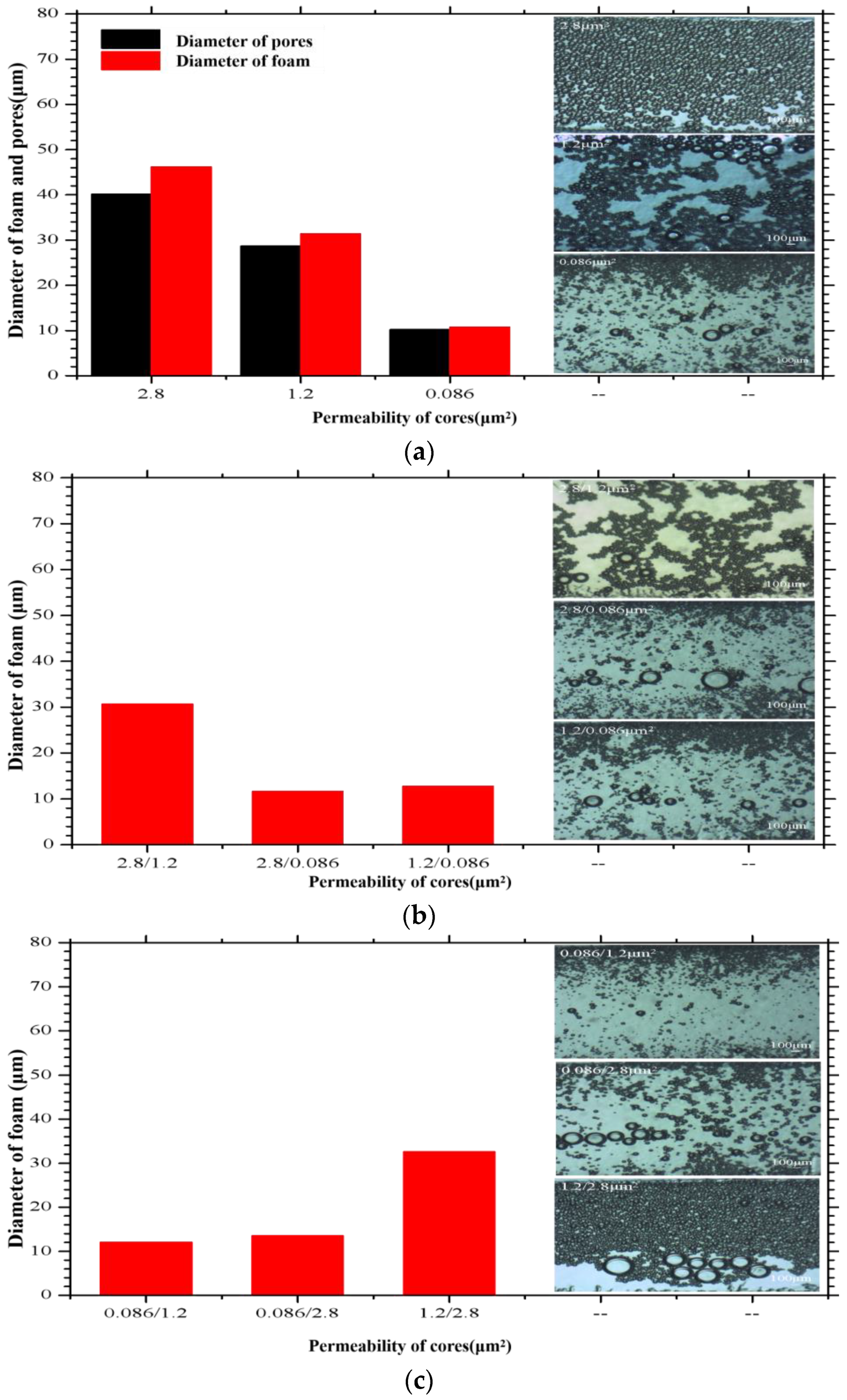
The particle size adaptation characteristics of foam in porous media are shown in Figure 2.
There is correlation and self-adaptation between the bubble diameter and pore diameter formed under different permeability. When the large diameter bubble formed by high permeability is injected into the low permeability layer, the bubble diameter decreases and achieves self-adaptation with low permeability. When the small diameter bubble formed by low permeability is injected into the high permeability layer, the bubble is more stable, and the diameter is comparable to the initial one with less change. It shows that the self-adaptation of the bubble and rock pore throat makes it match with the formation spontaneously, and there is no problem of poor matching of a traditional agent.
(2)
Dynamic characteristics of foam system in pore media
The foam is composed of surface-active liquid and gas. The biggest difference between it and the two components is that the flow resistance in the porous medium is different, which is mainly determined by the size and quantity of the foam, which is related to the permeability and porosity of porous media.
The experimental results show that when the foam passes through the seepage channel with a permeability of 0.013–4.58 μm2, it can be effectively blocked (As shown in Figure 3a). The blocking resistance coefficient is between 14 and 170 (As shown in Figure 3b). Due to the addition of polymer to the foam, the intensity of the foam liquid film increases, and it is not easy to defoam when the core sample is migrated. With the decrease of permeability, the pressure rises faster, and the foam system can meet the plugging requirements as the target reservoir permeability is in the range of 0.050–0.150 μm2.

3.4. Foam Stability Research

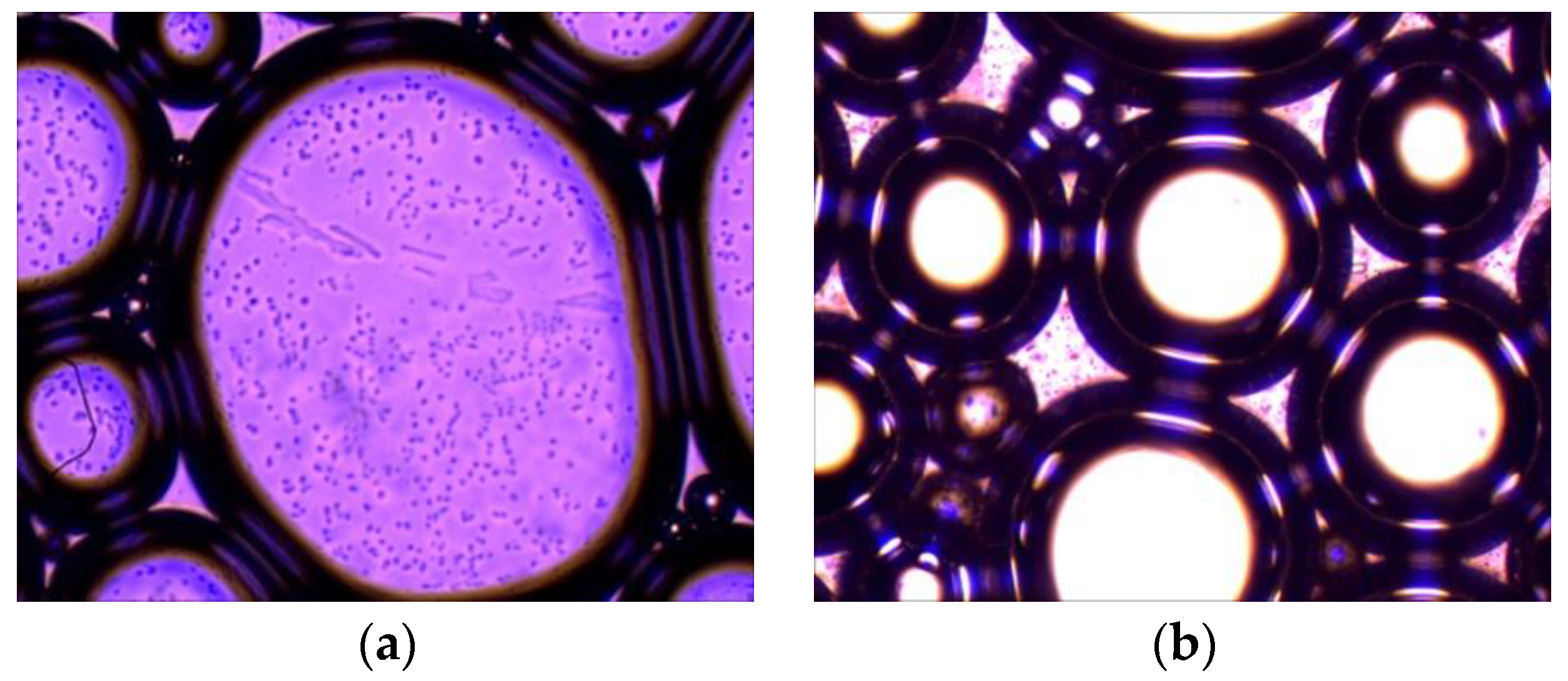
Since the surface of foam made of HPAM has high energy, the bubble system tends to minimize its own energy automatically, and the boundary of the bubble is very easy to rupture when influenced by external factors.
It is difficult for a single agent to shape stable foam (As shown in Figure 4a). To form a large number of stable foam systems, substances that can stabilize the foam should be added. Since the foam surface produced by HPAM is anionic, hydrophilic base surfactants with a cationic nature within the same molecule are used. Generally, the charge has the impact of preventing thinning of the liquid film and increasing the stability of the foam. Since two surfaces of the foam are charged, they attract each other so that the surfactant is adsorbed on the surface of the foam film, which gives the film elasticity and strength against external impact (As shown in Figure 4b). When the liquid film receives an external disturbance to expand or compress, there will come into being local thinning and reduction of the density of surfactant molecules adsorbed on the surface of the expanded or compressed area. The surface pressure causes the surrounding adsorbed molecules to diffuse to the deformation place so that the liquid film thinned by the impact becomes thick again. The density of surfactant molecules recovers, making the liquid film become stable and ensuring more efficient access to the rock pore space to achieve efficient blocking.

3.5. Adaptability of Combined Profile Control to Reservoir Permeability

3.5.1. Intra-Layer Heterogeneity

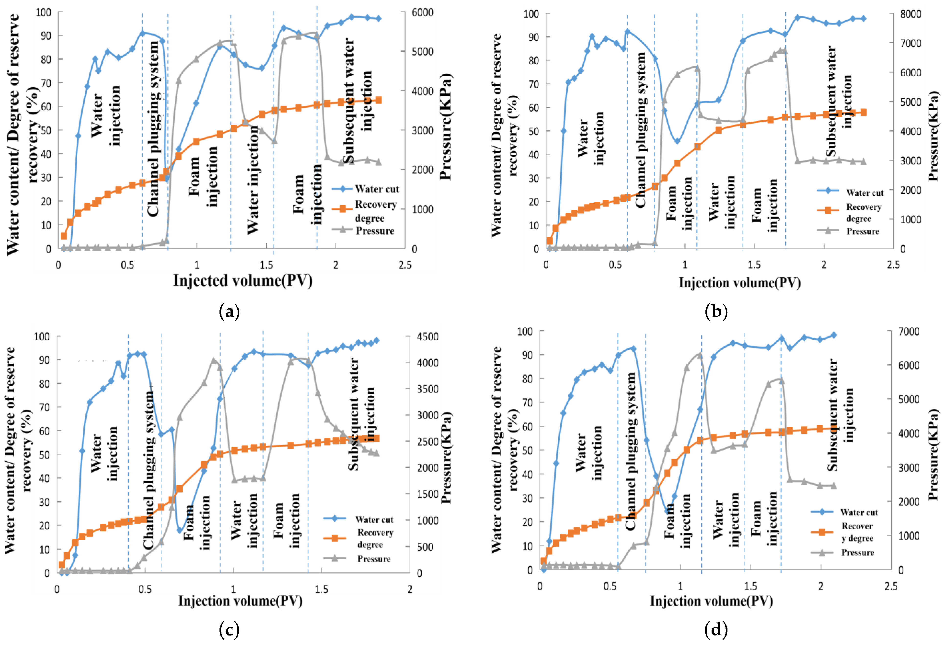
The increase of the recovery degree and the final recovery of each stage of the experimental scheme with different combinations of intra-layer heterogeneity permeability are shown in Table 6. The relationship between injection pressure, water content, and recovery factor and the injected PV number during the injection process of the intra-layer heterogeneous model experiment is shown in Figure 5.
As shown in Table 6, the final recovery degree of “a” is the highest at 62.61%, and “c” is the lowest at 56.72%. The final recovery degree of the four groups of experiments decreases with the increase of the permeability differential. The permeability of high and medium permeable layers in the cores of “a”, “b”, and “c” is the same. The injection pressure is higher in the foam and active water drive stage and lower in the primary water drive stage, which is due to the injected water preferential into the high permeable layer and easy to form water scour channels in the high permeable layer [18]. When the channel plugging system is injected and sealed, the pressure begins to climb, which indicates that the leading edge propulsion is relatively balanced. It can effectively enter the high-permeability layer with less seepage resistance and form stagnation, which reduces the mobility ratio [19]; when it becomes a gel and seals the high permeability layer, the number of molecules allowed to pass through the pore roar in the middle and the low permeability layer becomes less. However, the resistance for the foam to transport in the medium pore increases with the increasing volume of injection. When its additional resistance is greater than the seepage resistance in the pore roar, the foam is forced to flow into the middle and low permeability layers [20]. Therefore, the pressure rises in the first foam drive phase; in the second foam drive phase, the water content shows a decrease indicating that the foam entered the medium and low permeability layers again, and the increase of the recovery degree slowed down.
Comparing “b” and “d”, the permeability of high and low permeability layers in the core are the same except for the middle permeability layer, and the degree of water drive recovery is also the same. Since the channel plugging system shows better adaptability to the high permeability layer, the foam drive stage mainly flows through the middle and low permeability layers. Since the differential between middle and low permeability formations in “b” is equal to 10, and the grade difference between middle and low permeability formations in “d” is equal to 5, the degree of foam drive recovery and the final recovery rate in “d” are higher than those in “b”, which indicates that the near homogeneous formation is favorable for foam drive [21].

3.5.2. Inter-Layer Heterogeneity

(1) The recovery degree at each stage of the inter-layer inhomogeneous model with different permeability combinations and the recovery degree of each layer relative to the present layer are shown in Table 7.
As shown in Table 7, due to the presence of high permeability layers, the degree of recovery in the primary water drive phase is basically the same for the four inter-layer inhomogeneous models, with the highest degree of recovery of 20.61% for “e” and the lowest degree of recovery of 18.75% for “h”. The permeability of the medium-permeable layer is much smaller than that of the high-permeable layer. Therefore, the water drive stage basically flows into the high-permeable layer with less resistance in a similar recovery effect in the water drive stage. However, since the overall permeability of the middle and low permeability shows a gradual decline, the effect of injection water on the middle and low permeability formations in “e” to “h” becomes weaker [22]. Secondly, since the channel plugging system is similar to a pure viscous fluid with high viscosity, it can improve the mobility ratio in the reservoir and drive out the remaining oil in the high permeability layer where the seepage resistance is low.
There is a great increase in the degree of recovery of the high permeability layer in the injection channel plugging system stage, while the degree of recovery of the medium and low permeability layers is basically unchanged, implying that this system has good stratigraphic selectivity. Moreover, the foam fluid is a non-Newtonian fluid. With the influence of the molecular resistance between the gas and liquid interfaces of the foam fluid and the surface tension of the gas [23], when the carried particles in the foam fluid want to sink, they need to overcome the friction between the gas and liquid molecules and force the bubble to deform, which increases the resistance of the particles to fall. Thus, the high permeability layer is blocked by the channel plugging system, and the foam mainly enters the medium permeability layer and the low permeability layer to function.
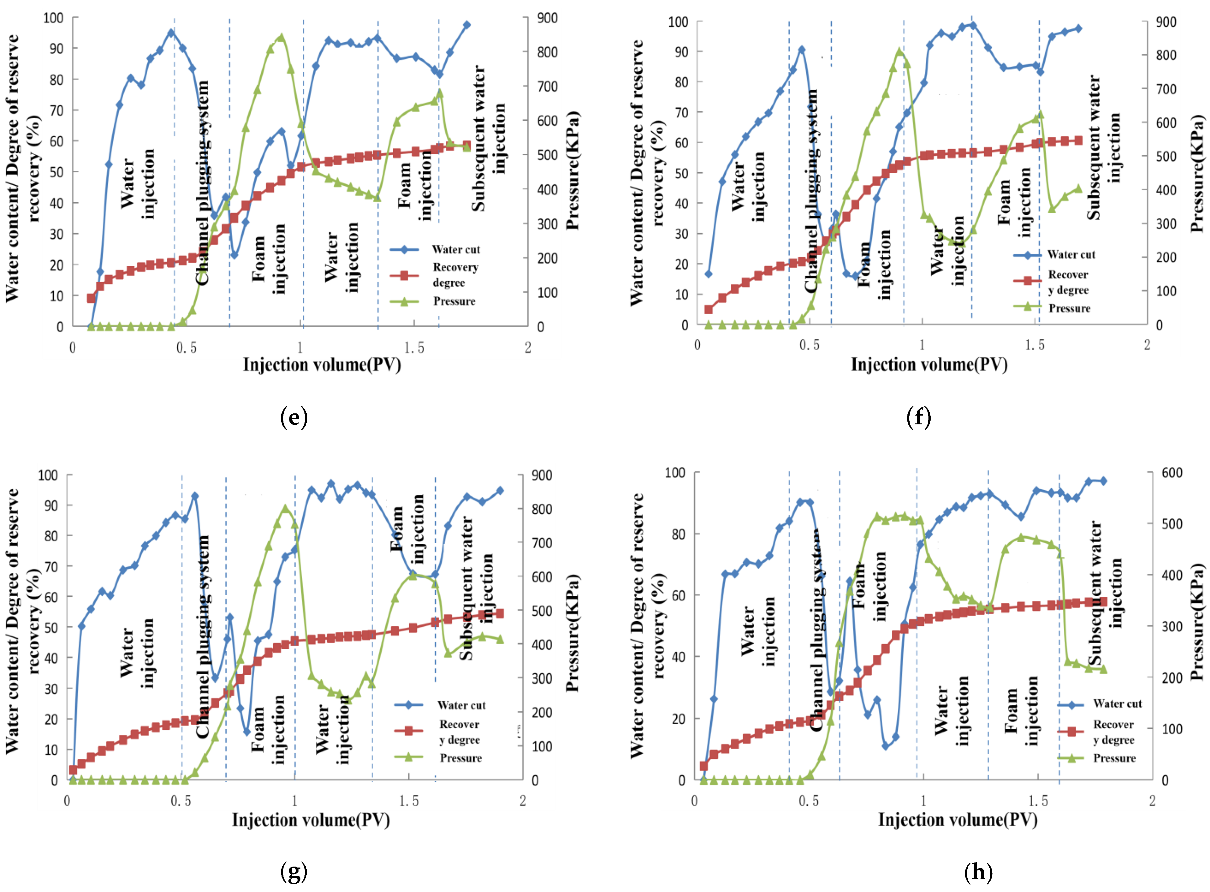
(2) The relationship between the injection pressure, water content, and recovery rate and the number of PV injected during the experimental injection of the inter-layer non-homogeneous model is shown in Figure 6.
The permeability of the high and medium permeability layers of “e”, “f”, and “g” is the same. The low permeability layer decreases from 500 μm2 to 100 μm2, and the permeability differential increases from 4 to 20. From the table, it can be seen that when the permeability differential is 10, the degree of recovery increases the most, while the effect becomes worse when the differential increases or decreases. When the permeability differential is small, the amount of foam injection increases for the low permeability layer. While in the middle permeability layer, which is the main layer, the amount of foam injection decreases. The degree of recovery from the middle permeability layer decreases, resulting in a decrease in the overall degree of recovery. For cores with a higher permeability differential, the additional pressure generated by the foam in the middle permeable layer is less than the injection pressure in the low permeable layer, resulting in less foam injection in the low permeable layer and a lower degree of recovery in the low permeable layer, leading to a lower overall degree of recovery [24]. The permeability of the high and low permeability layers is the same as that of “h”, but the permeability of the medium permeability layer is different. In “f”, in the foam injection stage, the increase of the recovery degree of the medium permeability layer is 58.85%, and the low permeability layer is 36.74%, which is higher than that of the medium and low permeability layers of “h”. With better injectability, the foam can produce a better plugging effect in the 2000 μm2 formation, and the recovery effect of “b” is better.

4. Conclusions

  • The ability of the pre-channeling plugging system’s adaptability to the reservoir directly affects the performance of the subsequent foam, which is of great significance. Therefore, it is necessary to completely seal the high permeability layer. When the permeability grade difference is equal to 10, the maximum increase in the degree of recovery is obtained. As the grade difference increases or decreases, the recovery rate will also show a decreasing trend.
  • The self-adaptability between bubble diameter and core pore diameter can spontaneously match with the reservoir, making up for the problem of poor matching of traditional plugging agents. With attention to the selection of bubble stabilizer and frother, the bubble volume and half-life reflect the degree of difficulty/ease and stability, both of which affect whether the bubble can play the role of deep transport in the reservoir.
  • For intra-layer and inter-layer heterogeneous reservoirs, the overall pressure shows a fluctuating rising pattern has developed. The foam transport process is influenced by pressure gradient and porous medium shear, which can instantly change the microscopic force of a porous medium and is conducive to starting crude oil. Therefore, the combination of multi-segment plug gel and foam is more effective and can effectively improve the development effect of medium and low permeability layers.

Author Contributions

Conceptualization, Y.Z., M.L. and C.W.; methodology, Y.Z.; software, J.Q. and Z.Z. (Zhen Zhou); formal analysis, C.W.; investigation, C.W., J.Q. and X.Z.; resources, Z.Z. (Zhaohai Zhan); data curation, Z.Z. (Zhaohai Zhan); writing—original draft preparation, C.W.; writing—review and editing, C.W.; visualization, J.Q., X.Z. and Z.Z. (Zhaohai Zhan); supervision, Y.Z.; project administration, Y.Z. and M.L. All authors have read and agreed to the published version of the manuscript.

Funding

The Fifth State Key Laboratory of Offshore Oil Efficient Development Open Fund Number: CCL2021RCPS0517KQN.

Institutional Review Board Statement

Not applicable.

Informed Consent Statement

Not applicable.

Data Availability Statement

Not applicable.

Conflicts of Interest

The authors declare no conflict of interest.

References

  1. Zheng, X.; Shi, F.; Cao, G.; Yang, N.; Cui, M.; Jia, D.; Liu, H. Progress and prospects of oil and gas production engineering technology in China. Petrol. Explor. Dev. 2022, 49, 565–576. [Google Scholar] [CrossRef]
  2. Li, C.; Wang, F.; Du, Q.; You, C.; Shan, G.; Li, B.; Zhu, S. Water displacement rules of sandstone reservoirs at extra-high water-cut stage. Petrol. Geol. Dev. Daqing 2021, 33, 163–171. [Google Scholar] [CrossRef]
  3. Nie, C. The influence of oil layer heterogeneity on the development effect of ASP flooding and its countermeasures: Taking the second-class oil layer of Daqing Oilfield as an example. Petrol. Geol. Oilfield Dev. Daqing 2022, 41, 110–114. [Google Scholar] [CrossRef]
  4. Pu, W.; Mei, Z.; Xin, J. Experimental study on W/O surfactant control and flooding in late high water-cut heterogeneous reservoirs. Sci. Technol. Eng. 2021, 21, 3090–3096. [Google Scholar]
  5. Wang, S.; Wu, X.; Han, G.; Zhang, S.; Ren, Z.; Jia, Y.; Yang, J. Experimental simulation of seepage law and flow field characterization in ultra-high water cut period of high permeability reservoirs. Sci. Technol. Eng. 2019, 19, 141–148. [Google Scholar]
  6. Su, H.; Zhou, F.; Liu, Y.; Gao, Y.; Cheng, B.; Dong, R.; Liang, T.; Li, J. Microscopic occurrence characteristics of emulsion in porous media and its control and displacement mechanism. Petrol. Explor. Dev. 2021, 48, 1241–1249. [Google Scholar] [CrossRef]
  7. Lu, X.; Cao, B.; Xie, K.; Cao, W.; Liu, Y.; Zhang, Y.; Wang, X.; Zhang, J. Re-understanding of the enhanced oil recovery mechanism of polymer flooding in heterogeneous reservoirs. Petrol. Explor. Dev. 2021, 48, 148–155. [Google Scholar] [CrossRef]
  8. Wang, J.; Huang, W.; Zhao, Y.; Zhang, Y.; Wang, D.; Zhang, L. Research on the applicability of nitrogen foam control and flooding technology in block Y of Xinjiang Oilfield. Oil-field Chem. 2022, 39, 288–294. [Google Scholar] [CrossRef]
  9. Zheng, J.; Zhang, G.; Pei, H.; Shan, J.; Jiang, P.; Wu, H. Three-phase foam control and flooding system to improve steam flooding recovery. Oil-Field Chem. 2022, 39, 82–86+92. [Google Scholar] [CrossRef]
  10. Liu, D.; Cao, W.; Yang, K.; Shi, X.; Wei, X.; Zhang, T.; Sun, S. Properties of anionic surfactant/tertiary amine compound foam and CO2/N2 response performance. Oil-Field Chem. 2022, 39, 331–337. [Google Scholar] [CrossRef]
  11. Wang, Y.; Meng, L.; Li, Q.; Liang, L.; Lan, J.; Jiang, B.; Xu, N. Preparation and properties of ternary composite CO2-enhanced foam system. Appl. Chem. Ind. 2021, 50, 295–298+330. [Google Scholar] [CrossRef]
  12. Meng, X.; Ju, Y.; Wang, C.; Li, X.; Wang, N.; Zhou, Z. Optimization and design of new step-by-step plugging control technology—Taking Bohai BZ34-3 oilfield as an example. Petrol. Geol. Dev. Daqing 2021, 1–11. [Google Scholar] [CrossRef]
  13. Wang, H.; Wei, J.; Zhang, Z.; Shi, D.; Xu, L.; Chen, Z.; Xiao, W. Experimental study on combined recovery technique. Complex Hydrocarb. Reserv. 2021, 14, 80–84. [Google Scholar] [CrossRef]
  14. Shan, J.; Pei, H.; Zheng, W.; Xie, H.; Zheng, J.; Zhang, G. Heavy oil steam sealing/oil repellent combination regulating technology. Oil-Field Chem. 2022, 39, 87–92. [Google Scholar] [CrossRef]
  15. Liang, S.; Li, Q.; Lv, X.; Zhou, Y.; Cao, W.; Lu, X. Multi-level profile regulating drive technology effect and residual oil distribution. Petrol. Geol. Dev. Daqing 2018, 37, 108–115. [Google Scholar] [CrossRef]
  16. Zhang, X.; Zhang, T.; Jiang, P.; Ge, J.; Zhang, G. Study on the improvement of carbon dioxide foam stability by modified silica nanoparticles. Chem. J. Chin. Univ. 2020, 41, 1076–1082. [Google Scholar] [CrossRef]
  17. Li, J.; Liu, Y.; Gao, Y.; Cheng, B.; Meng, F.; Xu, H. Effects of microscopic pore structure heterogeneity on the distribution andmorphology of remaining oil. Petrol. Explor. Dev. 2018, 45, 1043–1052. [Google Scholar] [CrossRef]
  18. Gao, J.; Zhang, N.; Wang, L.; Lu, X.; Xue, B.; Li, Y.; He, X. Influence and mechanism of profile control and flooding agent injection pressure on split rate. Oil-Field Chem. 2021, 38, 427–433. [Google Scholar] [CrossRef]
  19. Lu, X.; Gao, J.; He, X.; Wei, W.; Su, Y.; Pei, X. Experimental study on the internal channeling law of heterogeneous reservoirs in layers: Taking Daqing Lamadian Oilfield as an example. Petrol. Geol. Recovery Effic. 2022, 29, 1–8. [Google Scholar]
  20. Liu, Y.; Wang, J.; Yang, Z.; Hu, Z.; Lu, Y. Visualization experiment on the mechanism of residual oil activated by CO2 foam in heavy oil reservoirs. Oil-Field Chem. 2021, 38, 80–84. [Google Scholar] [CrossRef]
  21. Gu, Y.; Cai, S.; Li, D.; Zhang, L.; Sun, H.; Yang, Y.; Zhu, G.; Xu, Z.; Bao, B. Influence of porous media heterogeneity on water-oil immiscible flooding and mechanism analysis. Sci. Sin. 2022, 52, 807–818. [Google Scholar] [CrossRef]
  22. Zhang, Y.; Lu, X.; Wang, T.; Liu, Y.; Xia, H.; Chen, Y.; Pan, H.; Liu, J. Study on technology of multi-stage plugging and profile control for advantage channels in Bohai Oilfield. Petrol. Geol. Recovery Effic. 2018, 25, 82–88. [Google Scholar] [CrossRef]
  23. Zhao, F.; Yi, Z.; Lv, H.; Yao, F.; Yang, J.; Li, J. Performance evaluation and oil displacement mechanism of surface active polymers. Petrochemical 2021, 50, 1310–1316. [Google Scholar] [CrossRef]
  24. Cai, H.; Guo, S.; Cheng, L.; Zhang, Z.; Jia, P. Laboratory experimental study on interlayer interference of multi-layer commingled production in Bohai thin oil oilfield. Geol. J. China Univ. 2021, 27, 587–592. [Google Scholar] [CrossRef]
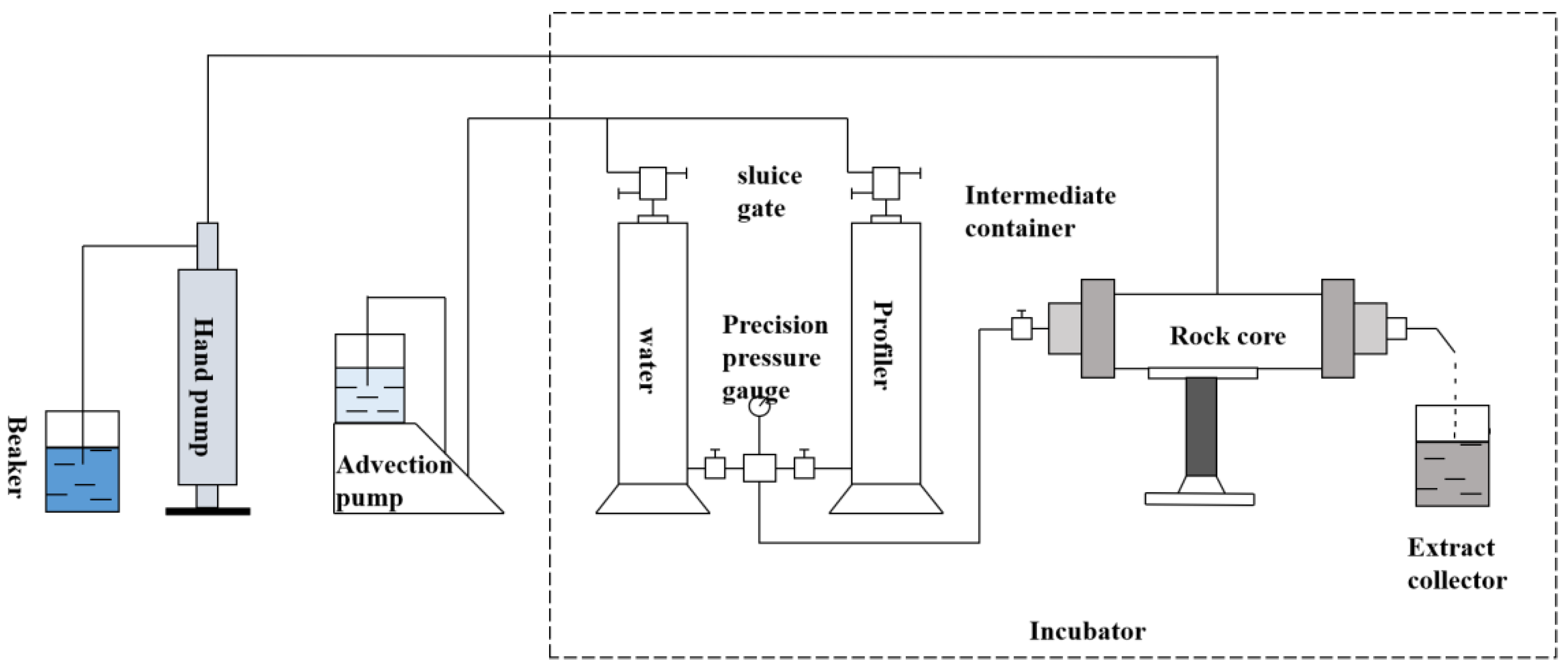
Figure 1. Flow chart of experimental equipment. (Note: Except for the advection pump, hand shaking pump and nitrogen bottle, other parts are placed in the 65 °C electric constant temperature oven.).
Energies 15 06203 g001
Figure 2. Particle size adaptation characteristics of foam in porous media. (Note: (a) shows the diameters of bubbles and the diameter of pores versus permeability. (b) shows the relationship between the diameters of the bubbles from the high permeability layer to the low permeability layer bubbles. (c) shows the relationship between the diameters of bubbles from the low permeability layer to the high permeability layer).
Energies 15 06203 g002
Figure 3. Foam seepage pressure difference, resistance coefficient, and residual resistance coefficient under different permeability rates. (Note: (a) shows the variation of foam pressure difference at different permeability. (b) shows the change of resistance coefficient and residual resistance coefficient at different permeability.).
Energies 15 06203 g003
Figure 4. Microstructure of the foam. (Note: (a) shows without adding the foaming agent, and (b) shows adding the foaming agent).
Energies 15 06203 g004
Figure 5. Dynamic curves of oil displacement experiments with intra-layer heterogeneity. (Note: These four scheme (ad), all show the relationship between water content/Pressure/Degree of reserve and injection volume at different stages.)
Energies 15 06203 g005
Figure 6. Dynamic characteristics of oil displacement in the inter-layer heterogeneous model. (Note: These four schem (eh), all show the relationship between water content/Pressure/Degree of reserve and injection volume at different stages.)
Energies 15 06203 g006
Table 1. Water quality analysis.
Ion Composition and Content (mg/L)Total Salinity
(mg/L)
K+Na+Ca2+Mg2+ClSO42−CO32−HCO3
2735.03192.5829.614624.5230.20.0445.888057.82
Table 2. The strength of the channel plugging system at different concentrations of main agent and cross-linking agent.
Main Agent A (%)Main Agent B (%)Crosslinking Agent (%)Average Energy
Storage Modulus (Pa)
Average Loss Modulus (Pa)Viscosity before Gelation
(mPa·s)
Viscosity after
Gelation (mPa·s)
330.00553.89.614.525,800
3.53.5102.918.819.643,753
44167.317.028.350,140
330.01102.918.815.439,080
3.53.5149.213.322.446,973
44260.517.235.855,946
330.015213.819.719.543,426
3.53.5236.822.526.747,566
44336.324.040.977,166
Table 3. The strength of the channel plugging system with initiator as variable.
Initiator
(%)
Gel-Forming Time
(h)
Average Storage Modulus
(Pa)
Average Loss Modulus
(Pa)
Viscosity after Gel Formation
(mPa·s)
0.0057.5462.539.1108,500.0
0.015.5458.141.8103,520.0
0.0154.5416.336.6101,460.0
0.023.0405.636.7102,293.3
Table 4. Preferred foaming agent concentration.
Foaming Agent Concentration
(%)
Foaming Volume
(mL)
Half-Life Period
(min)
Comprehensive Value
(mL·min)
0.3410208200
0.44302510,750
0.54402711,880
0.64302611,180
0.74152510,375
Table 5. Effect of foam stabilizer concentration on foam performance.
HPAM
(%)
Foaming Volume
(mL)
Half-Life Period
(min)
Modified CMC Concentration
(%)
Foaming Volume
((mL)
Half-Life Period
(min)
044027044027
0.05435720.3350160
0.14151110.5300228
0.24101980.6290275
0.33652230.7270320
Table 6. The experimental results of the heterogeneous combination of different permeability in the layer.
SchemePermeability (×10–3 μm2)Waterflooding Recovery Degree (%)Increase in Recovery Degree of Compound Flooding (%)The Lowest Point of Moisture Content Drop (%)Final Recovery Degree (%)
a4000/2000/50027.5335.0829.4162.61
b4000/2000/20021.6836.2145.6857.89
c4000/2000/10021.6635.0417.9556.70
d4000/1000/20021.6337.4624.4459.09
Table 7. Comparison of oil drive effect of inter-layer inhomogeneous model with different permeability combinations.
SchemeCore (×10–3 μm2)Stage Cumulative
Recovery Degree (%)
(Each Sublayer)
Stage Recovery
Degree Increase (%) (Each Sublayer)
Stage Cumulative
Recovery Degree
(%) (Overall)
Stage Recovery
Degree Increase (%) (Overall)
Water Drive Channel Plugging SystemFoam FloodingChannel Plugging SystemFoam FloodingWater Drive Channel Plugging SystemFoam FloodingChannel Plugging SystemFoam Flooding
e600045.5669.0971.9323.532.8420.6131.5858.5310.9726.95
20004.326.7857.882.4651.1
5002.033.9838.941.9534.96
f600045.3070.6672.6525.361.9920.2230.9160.6010.6929.69
20005.296.2965.141.0058.85
2001.672.5039.240.8336.74
g600046.5972.3574.0825.761.7319.2329.0754.439.8425.36
20005.035.6052.480.5746.88
1001.421.9632.770.5430.81
h600046.1773.0974.8626.921.7718.7529.0557.8410.3028.79
10004.234.9059.130.6754.23
2001.201.6736.730.4735.06
Publisher’s Note: MDPI stays neutral with regard to jurisdictional claims in published maps and institutional affiliations.