Abstract
The maintenance of wireless sensor networks involves challenges such as the periodic replacement of batteries or energy sources in remote locations that are often inaccessible. Therefore, onboard energy harvesting solutions can provide a viable alternative. Experimental energy harvesting from fluid flow, specifically from air flow, is typically restricted to a rotor and stator design or a model that strikes a piezoelectric. On the other hand, energy harvesting from mechanical vibrations routinely uses the linear motion of a magnet passing through a coil or vibrating piezoelectric elements. In this paper, we propose a novel V-twin harvester design that converts wind energy from a rotational input into the linear motion of a magnet inside a coil via a crank-slider mechanism. This design allows for high performance with a smoother voltage output when compared to a reference rotor/stator harvester design or piezoelectric method. At 0.5 Hz, a single crank-slider generated a voltage of 0.176 Vpp with an output power of 0.147 mW, whereas the reference harvester generated 0.14 mW at 1.0 Hz with a 0.432 Vpp. A single crank-slider operating at regulated frequencies of 0.5, 1, 2, and 3 Hz, with a stroke length of 50 mm and a generated continuous power of 0.147, 0.452, 2.00, and 4.48 mW, respectively. We found that under ambient wind speeds of 3.4 and 4.1 m/s the V-twin formation with the optimized configuration, in which the coils and loads were both connected in series, generated 27.0 and 42.2 mW, respectively.
1. Introduction
The quantity of electronic devices used in our everyday interactions creates a significant demand for electrical power. However, that power comes at a cost, be it monetary, pollution, radiation, or resource depletion. Since 1950, the volume ofretail sales of US electricity has increased from 0.3 trillion kWh to 4.0 trillion kWh [1]. A major concern is whether civilization will be able to globally sustain this rate of consumption. Current estimates suggest that the world’s oil reserves may last for only the next 50 years [2]. This limited supply of resources has pushed society to look towards alternative and innovative methods of developing usable energy. The most common large-scale energy alternatives used today are nuclear, wind, solar, hydro, thermo, and bio-fuels. Each of these alternatives has its own benefits and drawbacks. One of the major limitations of each of these is the scope and scale in which they are viable. These listed alternatives require a significant investment in order to be sustainable but their outputs can reach the gigawatt range.
Although power can and is harvested from the previously mentioned alternative sources in order to satisfy the needs of large-scale consumption, there are options available for small-scale devices to harvest their own energy. For example, self-winding watches use the motion of the human body to self-wind the mainspring in order to continually power the device. This energy-providingmotion is readily available, not limited by our depleting natural resources, and easily offsets the power consumption that would otherwise be used by the device. A small-scale energy harvesting device is, by definition, a mechanism that converts energy from an external source into useful electric energy that can provide on-board energy solutions to micro-robots, wrist watches, etc. [3]. Several of the options that are readily available to the average consumer have the following shortcomings:
- Wind/hydro/fluid flow: Requires adequate wind speed, orientation, and a very high contact area.
- Solar: Requires ideal conditions with no cloud cover and a proper angle. Additionally, its components have a high decay rate.
- Electromagnetic: Has size requirements and its moving components can experience failure;
- Piezoelectric: Outputs a high voltage with a low current and its moving components can experience failure.
- Vibration/linear: Must be in line with the device, operate at natural resonance for the maximum output, and its moving components can experience failure.
- Rotational: Produces significant forces when the masses rotate at a large radius, has moving components that can experience failure, and is generally associated with fluid flow, which has several additional restrictions (see above).
Electromagnetic energy harvesting is one such small-scale harvesting method that utilizes mechanical vibrations and oscillations coupled with piezoelectric, electrostatic, magnetostrictive, and electromagnetic devices to generate electricity [4,5,6]. For example, a piezoelectric tile used in an energy harvesting device placed in a person’s shoe can generate up to 39 V [7]. Electrostatic devices are also capable of high power output, obtaining up to 549 W using a 1 cm chip with an acceleration of 0.6 g [8]. At the current state of development, small-scale devices can range in power consumption from 1 W for micro-bots up to 10 mW for wireless sensors and hearing aids [9]. With optimization, there are now energy harvesters that generate over 0.1 mW/cm [10]. Myers et al. designed a small-scale windmill, harvesting 5 mW of continuous power at an average wind speed of 10 miles per hour [6]. Dinulovic et al. developed a rotational electromagnetic harvesting transducer that generated 4 mJ at a load of 10 ohm [11]. Luong et al. used a magnetic force exciter to vibrate a piezocomposite generating element in a small-scale windmill [12]. It was able to charge a 40 mA battery in approximately 3 h using natural wind in an urban area. Wang et al. developed a wind energy harvester that generated high power at a high wind speed of 20.3 m/s [13]. Based on several of these experimental designs, an energy harvester the size of a shoe box would have the capacity to charge a cell phone which would use approximately 2 W when charging. Considering the fact that there are over 4 billion cell phones in the world, energy harvesters have the potential to dramatically offset the usage of limited resources. A barrel of oil represents approximately 1700 kWh of energy [14]. Assuming that each cell phone user only charged their device once per week for two hours, harvesters would save roughly half a million barrels of oil per year.
Even though energy harvesters do not fulfil the role of providing energy storage, due to improvements in electronics efficiencies, cost, demand, and flexibility [15], they present an interesting option for creating self-powered electronics, emergency energy assistance, supplemental energy, and so on. A long-term and resilient self-powered device that requires little or no maintenance would serve not only to offset resource consumption but would provide devices that fit a variety of unique situations. For example, medical implants and sensors that monitor or assist in human bodily functions would greatly benefit from a long-term alternative to recharging the device externally and periodically by utilizing piezoelectric or similar devices [16]. Additionally, with ongoing expansion in space exploration, there is a potential demand to develop self-powered electronics. Currently, many such devices have focused on solar power dependence [17,18,19], yet other sources remain widely unexplored for space applications.
Although the abovementioned mechanisms, such as the piezoelectric effect, the magnetoelectric effect, and magnetostriction, can utilize mechanical vibrations or mechanical energy and convert that into electrical energy [6,20,21], the actual power output and efficiency of these devices is much lower compared to the energy requirements of electronic devices (on the order of several milliwatts [10,22,23]). Hence, in order to harvest high power at lower frequencies, inductive energy harvesting becomes a more reliable solution. Of all the vibration-based electromagnetic harvesters, perhaps one of the most common and simplest is the permanent magnet and coil configuration, which is a linear harvester, as shown in Figure 1. In this arrangement, a coil experiences a changing magnetic field resulting from an oscillating permanent magnet. It is well known from Faraday’s law that electromotive force () is effected by the number of coils (N) in a changing magnetic flux () over a change in time (t), as seen in Formula (1). When keeping the volume of the coil space constant, can be increased by decreasing the diameter of the wire gauge, which in turn increases the number of turns of the coil. Additionally, increasing the frequency of oscillation also increases . Finally, improving will also increase the output of the harvester. An advantage of this type of harvester is that it can also be easily magnetically coupled or even have its dampening tuned to increase the overall output [23,24].
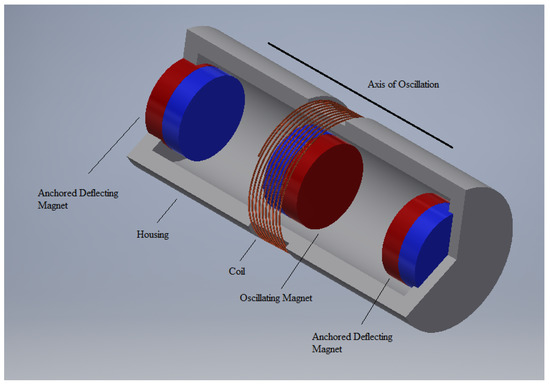
Figure 1.
Example of a common small-scale electromagnetic energy harvester, which typically uses one degree of freedom along the axis of oscillation as a method of harvesting energy using vibrations.
Magnetism and magnetic materials have been studied for several centuries for their unique properties and applications. Using Faraday’s law of induction, an electromotive force is generated when an electrical conductor is subjected to a changing magnetic field. Several studies have been carried out to investigate energy generation using electromagnetic induction from a variety of sources, such as mechanical vibrations, fluid flow, wind, and mechanical movement. In this study, we investigated the conversion of small-scale rotational energy into electricity using Faraday’s law of electromagnetic induction by incorporating a a crank-slider design with a linear electromagnetic energy harvesting system. We believe that the energy generated by such a device can be used for powering small-scale electronic devices.
Researchers are continually exploring several additional styles of experimental harvesting devices. One such design, which uses the typical magnet and coil configuration, is the swing-magnet type, which is used in harvesting bicycle vibrations [25]. Another more common and established configuration of energy harvesting is the previously mentioned large-scale harvesting systems using turbine-style harvesters with wind or water. The most common and recognizable wind harvesters are the large two- and three-bladed versions of the horizontal-axis wind turbines (HAWT) [26,27] generally seen in large wind farms. Similarly to how an airplane flies, these systems use aerodynamic lift to turn the blades to rotate a shaft that turns the generator [28]. With this type of system, the blades, shaft, and generator are all aligned on the same axis of rotation along the central hub holding the blades and through the generator [27,28].
One of the major uncertaintiesassociated with these HAWT-style systems, or any similar-style harvester, is where to locate the magnets and coils required for electromagnetic harvesting. A rotating object is subject to significant forces () that are directly proportional to the location of mass (m) and the square of the velocity (V) at the point of rotation, as shown in Formula (2). Furthermore, as shown in Formula (3), the inertia (I) is also greatly affected by the location of mass (m). Therefore, attaching a dense material such as a neodymium magnet or a copper coil with densities of approximately 7300 kg/m and 8920 kg/m, respectively, as part of the spinning blades would be unfavorable compared to the commonly used carbon epoxy composite or graphite epoxy composite, which have respective densities of 1446.2 kg/m and 1580 kg/m [29].
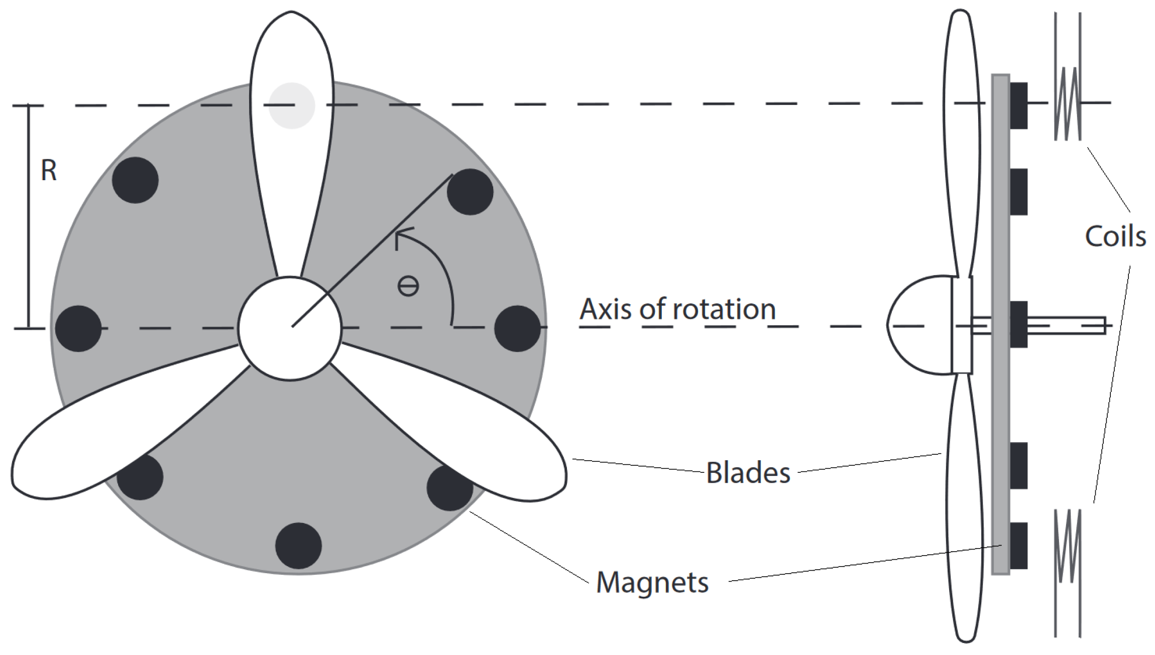
Some novel smaller designs have attempted to attach the magnets as part of the blades or as separately rotating components at a radius equivalent to the blades. In these designs, presented in Figure 2 and Figure 3, the magnets move about the axis of rotation at some relatively significant radius. Although they are effective, these designs introduce problems with rotational forces and inertia, as presented in Formulas (2) and (3). As a method to further evaluate our proposed crank-slider design, in this paper we construct and analyze a rotor/stator device based on the designs presented in Figure 2 and Figure 3 and refer to it as the reference harvester.
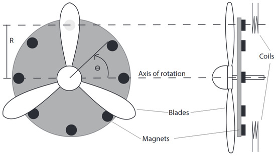
Figure 2.
Example of a rotational energy harvester that has the magnets rotating at a radius similar to that of the fan blades [22,30]. Here, although the magnets are not attached directly to the blades, they still have a significantly large mass spinning at a relatively fast velocity and at a large radius from the axis of rotation.
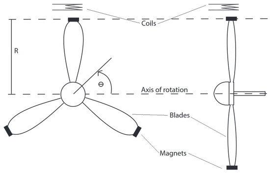
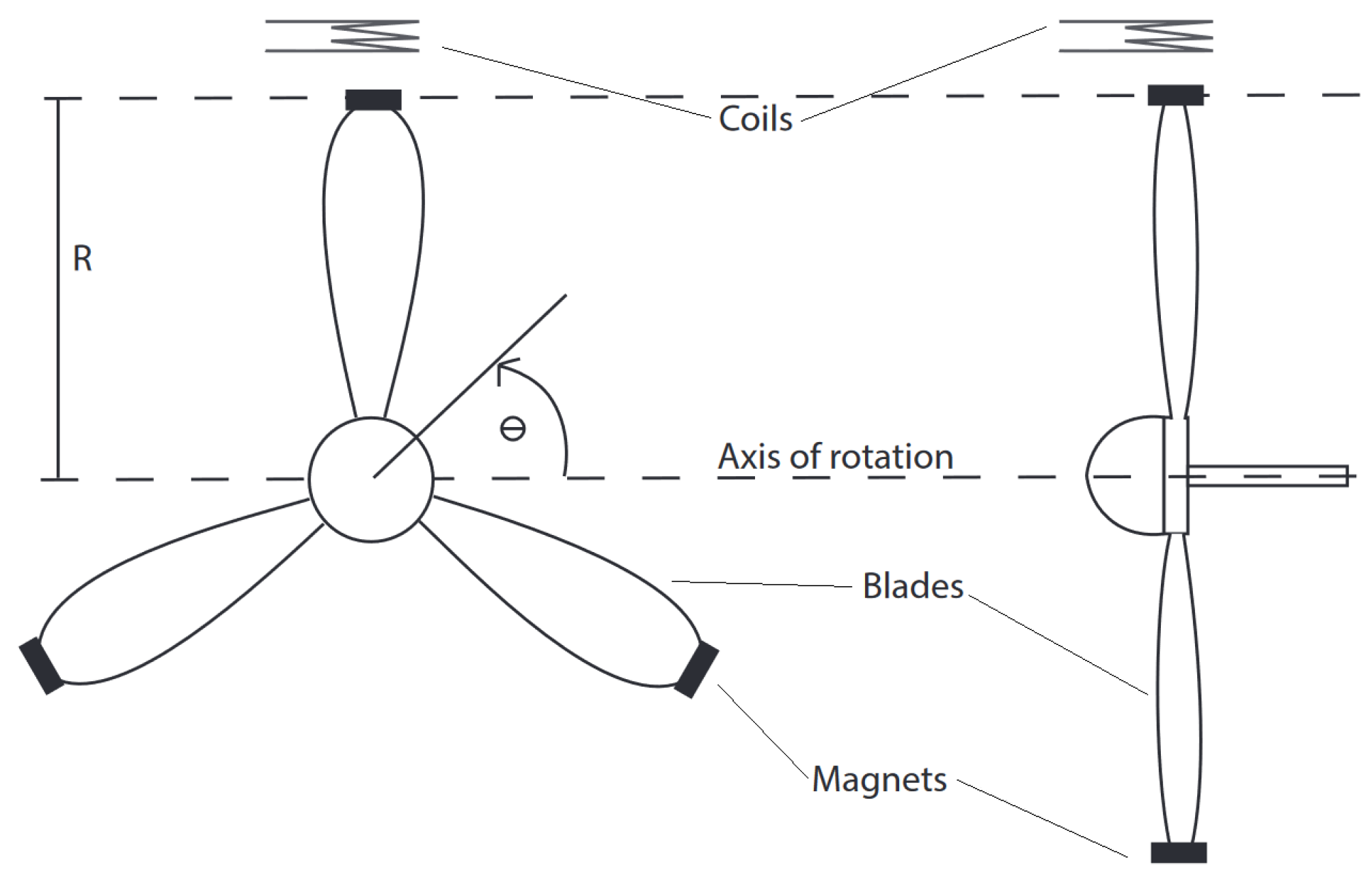
Figure 3.
Example of a rotational energy harvester that has the magnets attached to the fan blades [31,32,33]. In this design, the mass of the magnets at such an extreme radius has a significant effect on the stability, inertia, and structural integrity of the system.
This paper is organized as follows. In the introduction we present a background on electromagnetic harvesters, the need for innovative designs, and the current state of small-scale energy harvesting. In the Section 2, we cover the proposed design, the kinematics of a crank-slider, and the design of the reference harvester. Additionally, in the Section 2, we discuss the formulas used for the evaluations and theoretical outputs of the design. In this section, the formula and kinematics presented are used in combination with COMSOL Multiphysics software for the simulation and modeling of magnetic fields as a method to generate computer-driven predictions for theoretical outputs for the system. For further theoretical evaluations, in the Section 2 we provide a measured prediction, obtained using a Teslameter to physically gather data from the magnetic field. These data were used as the inputs for the formulas to provide an additional set of theoretical outputs for the system. The Section 3 comprises two subsections which separate the single crank-slider harvester topic from the modified V-twin harvester. The first subsection covers the plots produced by the experimental device, including optimized values for power production for the single crank-slider harvester alone. This subsection also presents a comparison of the crank-slider design with the reference harvester, along with their strengths and weaknesses. The second subsection presents a V-twin harvester that utilizes two of the crank-slider harvesters. This subsection provides several output arrangements and compares them to obtain the optimal configuration. Finally, in the Section 4, we present the reader with a novel expansion of the experimental crank-slider harvester, obtained by modifying the design to include the addition of a second crank-slider in the form of a V-Twin-style harvesting device. The Conclusions include relevant data gathered from the V-Twin harvester, along with its possible applications. The final V-twin harvester configuration proposed in this study consists of the following:
- A wind harvester that has the capacity to function at low speeds (3.4 m/s);
- A novel way of converting rotational motion to linear motion via a crank-slider mechanism in a harvester;
- A harvester that is easily transported and small-scale;
- A harvester design that can be easily adapted for higher output by adding more crank-slider mechanisms to the system;
- A rotational design that experiences lower detrimental forces on its components compared to similar designs; and
- A configuration that has a comparable power output to other similar devices, without experiencing potentially damaging high peak voltages.
2. Materials and Methods
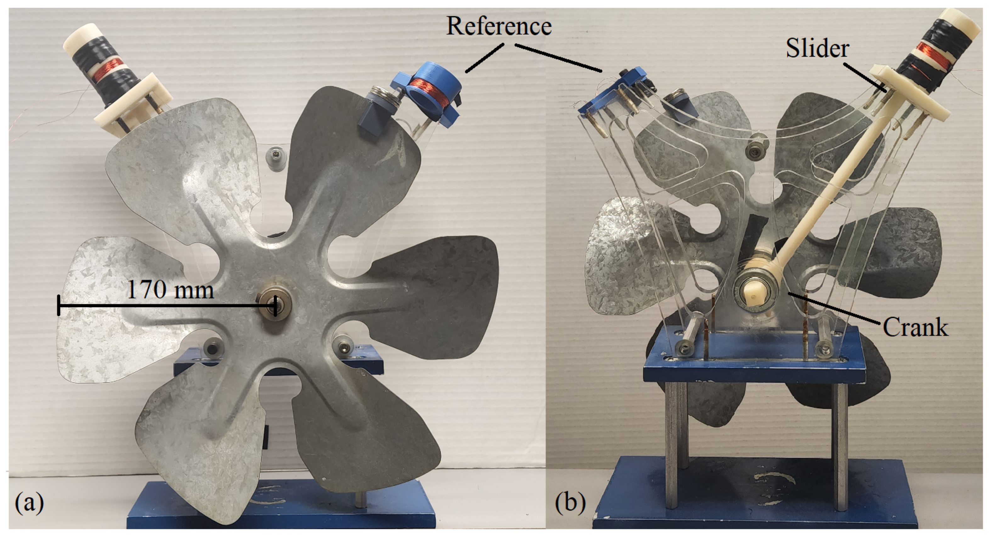
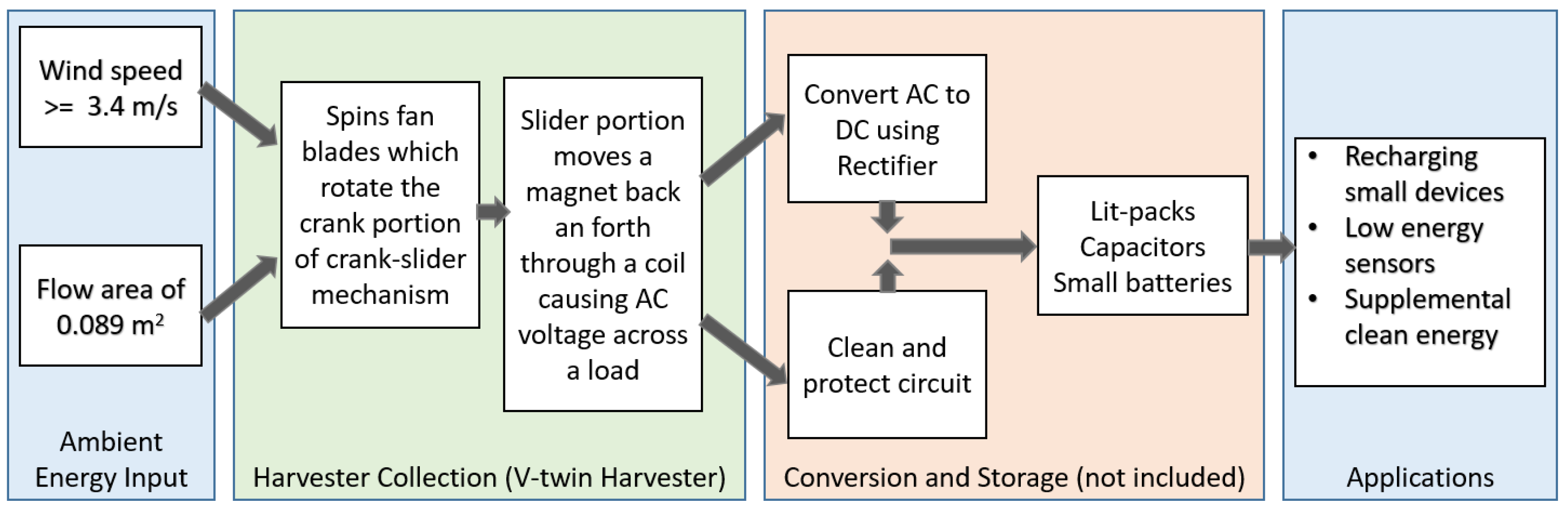
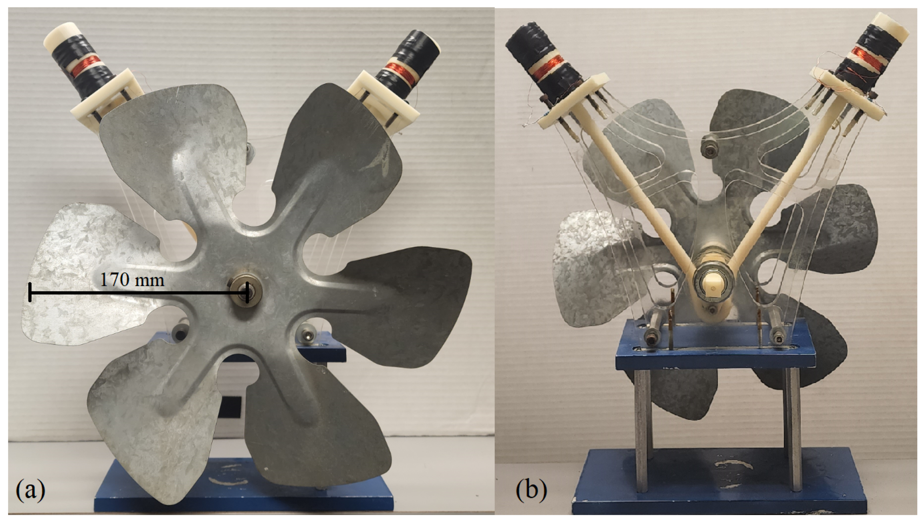
Figure 4 shows the crank-slider harvester prototype, along with a reference harvester similar to the ones presented in Figure 2 and Figure 3. The crank-slider kinematics for the dimensions in Figure 5 are outlined in Formulas (4) through (10). The crank-slider harvester has a crank radius (r) of 25.3 mm, an arm length (l) of 222 mm, and a piston distance (d) of 13.9 mm. Formulas (11) through (14) express the rotational mechanics associated with the experimental reference harvester. The experimental reference harvester has a radius (R) of 192 mm. Both the crank-slider and the reference harvester each have two N52 axially magnetized disk magnets with a diameter of 25.4 mm and a thickness of 3.175 that are attached for a total thickness of 6.35 mm and a of 1.48 T. Both coils (one for the crank-slider and one for the reference harvester) are composed of coated AWG 32 wire, with 150 turns, an inner coil diameter of 29.2 mm, a width of 7.5 mm, a resistance of 8.1 , and a wire length of 14.03 m. In Figure 6, the components included in this device are included within the “Harvester Collection” portion. In order to operate the device, it can be placed on a flat surface and it will operate under wind speeds as low as 3.4 m/s. Furthermore, it can be incorporated with a “conversion and storage” system, which is not included as part of this study, as a method to power or recharge small devices and low-energy sensors and to provide supplemental clean energy.

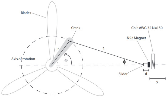
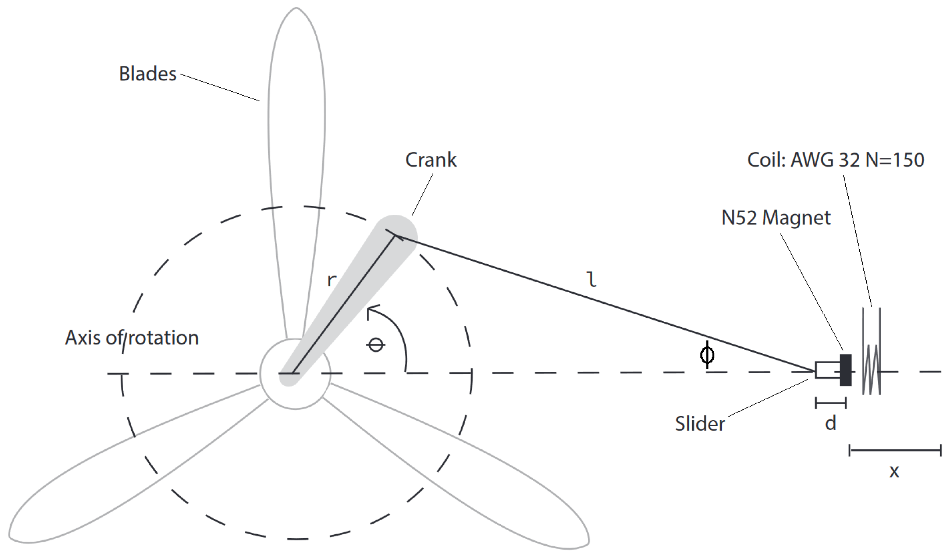
Figure 5.
Crank slider mechanism in which the slider is aligned along the axis of rotation for the crank.
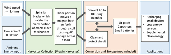
Figure 6.
Schematic of wind harvesting process.
The kinematic analysis for the magnet attached to the piston of the crank-slider along the axis of oscillation is as follows. The point x in Figure 5 represents where the crank-slider harvester’s magnet is in relation to its distance from the axis of rotation from the driving wheel and is represented as x in Formula (4). This does not take into account the position of the coil, which could be theoretically placed anywhere along the travel path of x. It does include the additional mechanical components required to attach the magnet to the slider, which are represented as d, the distance from the center of the magnet along the axis of travel connecting at the point l.
The velocity () of the magnet at point x along the travel path in Figure 5 is represented by Formula (5). As shown in Figure 5, the relation of and is expressed in Formula (6) and rearranged into Formula (7). Using Formula (7), in Formula (5) is replaced, resulting in Formula (7).
In this paper, l will always be assumed to be at least four times greater than r; therefore, the acceleration () of the magnet at point x at along the travel path in Figure 5 can be approximated with Formula (9), where is no longer a component [34].
Furthermore, it is assumed that the propulsion of the fan is at a constant velocity in order to evaluate the system. With a constant velocity, the angular acceleration () is zero and the first component of Formula (9) can be eliminated, resulting in the reduced Formula (10) [34].
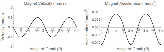
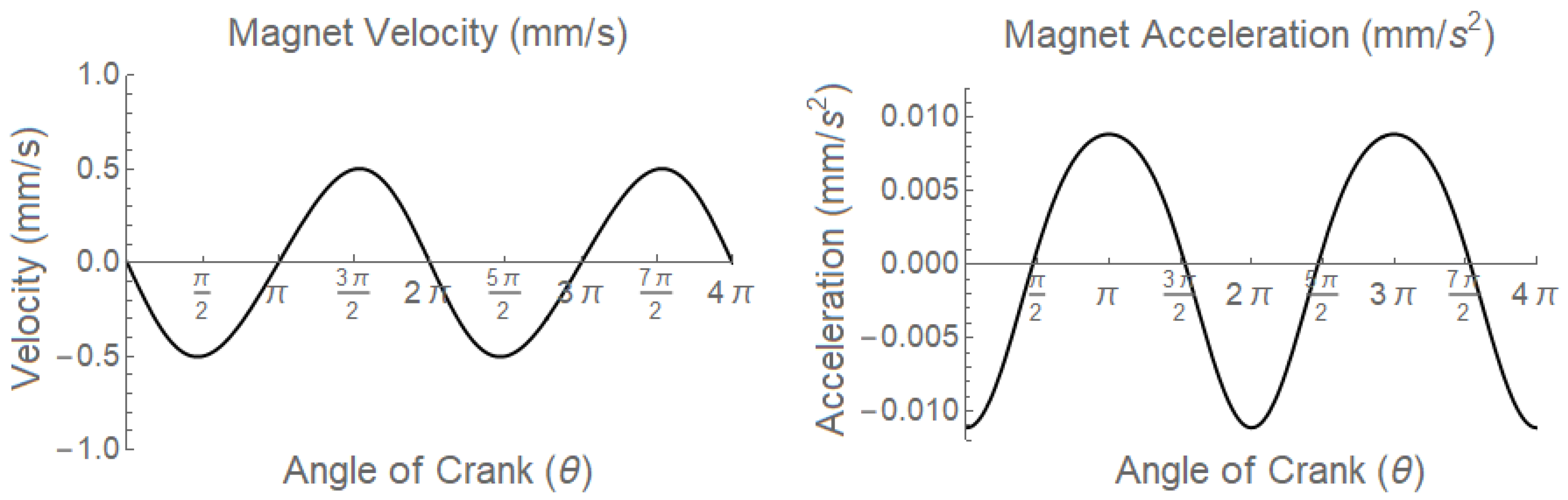
Figure 7 is a sample output of from Formula (8) and from Formula (10) with the given values for , r, and l for this experiment. It is significant to note the critical components of motion for the magnet. At values equal to 0 or and multiples thereof, the magnet is outside the coil, its is zero, and the magnet is at its minimum and maximum positions relative to the crank. At of , 3, and their multiples, the magnet’s is zero and this is where the theoretical and experimental central position of the coil ismounted. Additionally, the maximum acceleration of the magnet portion of the crank-slider harvester occurs when is 0, where the mechanism is at its elongated maximum, and the magnet is outside the coil.
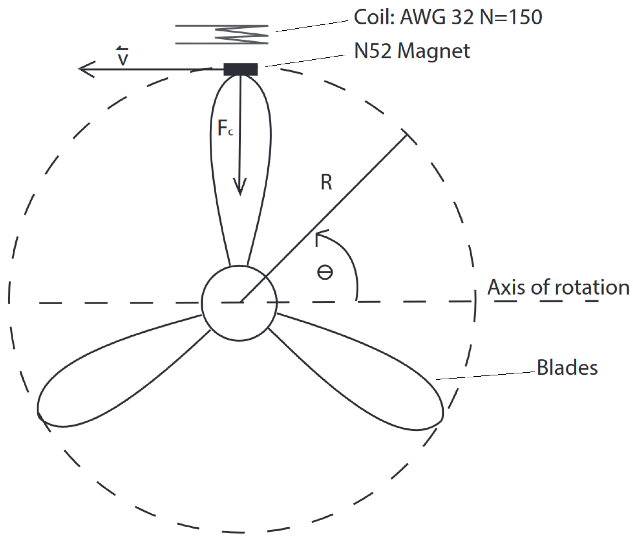
An evaluation of magnet’s movement when rotating at the circumference of the edge of the fan blade, as shown in Figure 4 and Figure 8, was performed using the following well-known formulas. The arc distance traveled (D) by the magnet from the initial position is given in Formula (11). The speed (V) of the magnet in Figure 8, given a uniform circular motion, is represented in Formula (12). The centripetal acceleration () and force () on the magnet due to are given in Formulas (13) and (14), respectively.
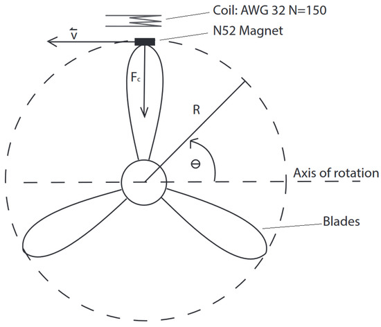
Figure 8.
Reference turbine-style harvester with magnets attached to the tips (max radius) of the blades and coil attached to the stationary surface, similar to the designs presented by [22,30].
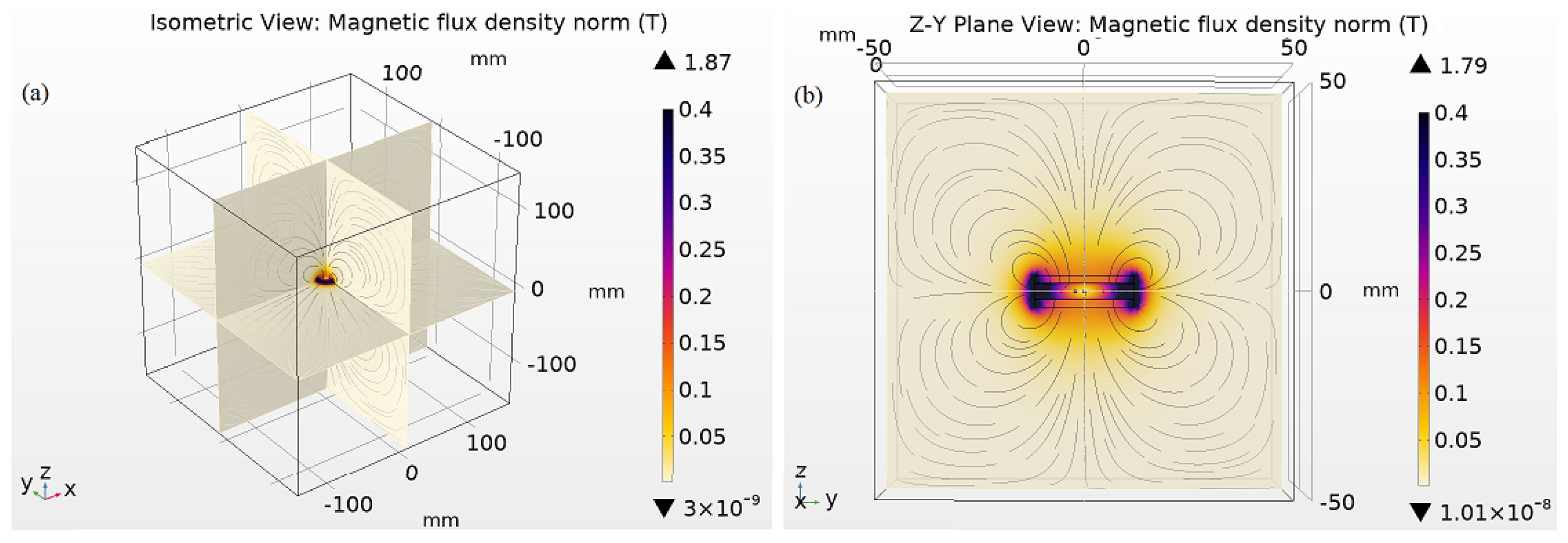
For a crank-slider harvester which utilizes the style presented in Figure 1, the induced voltage () from the motion of a conductor within a magnetic field (B) over a length of wire (L) at a velocity () is shown in Formulas (15), (16), and reduced to (17) [36]. The values for B are assessed for theoretical analysis in two ways: using the COMSOL values seen in Figure 9 and using the physical readings from a WT10A Teslameter. Those values are plotted in Figure 10.

Figure 9.
COMSOL-generated field based on two N52 axially magnetized disk magnets with a diameter of 25.4 mm and a thickness of 3.175 that are attached for a total thickness of 6.35 mm and a of 1.48 T along the z-axis, as referenced in Figure 5 and Figure 8. (a) Isometric view with the original boundary conditions of −150 mm to 150 mm used for the data simulation process and theoretical predictions. (b) Emphasis of the field at close proximity to the magnet surface along the ZY plane.
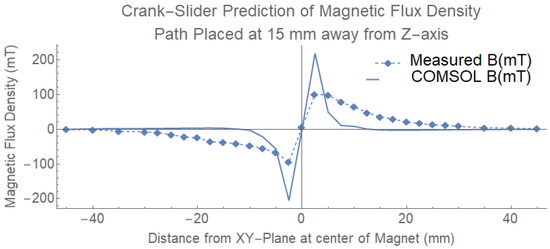
Figure 10.
A sample of values for B through the coil along the axis of oscillation. The measured values were physically collected using a WT10 Teslameter at the indicated distances. The COMSOL values were extracted from Figure 9 at a distance of 15 mm from the z-axis (the center of the magnet) and along the axis of oscillation extending ±25 mm from the XY-plane.
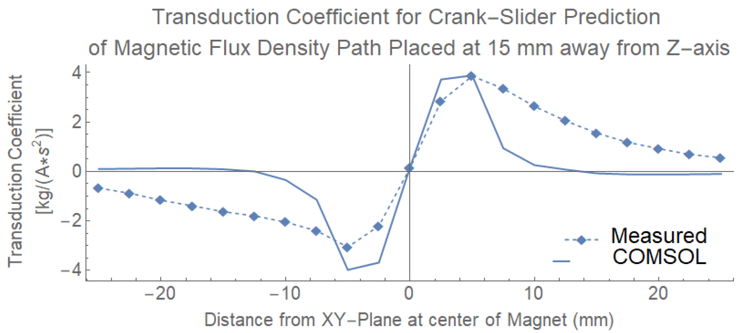
In Formula (17), is also referred to as the transduction coefficient (); see Formula (18) [36]. The values for B from Figure 10 were used to generate in Figure 11.
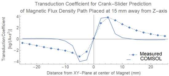
Figure 11.
Representation of the transduction coefficient () based both the measured and COMSOL prediction values from Figure 10 with the l value for the crank-slider harvester. This image represents a one-half stroke from 0 to of the crank, which would originate at −25 mm and extend to +25 mm from the center of the coil.
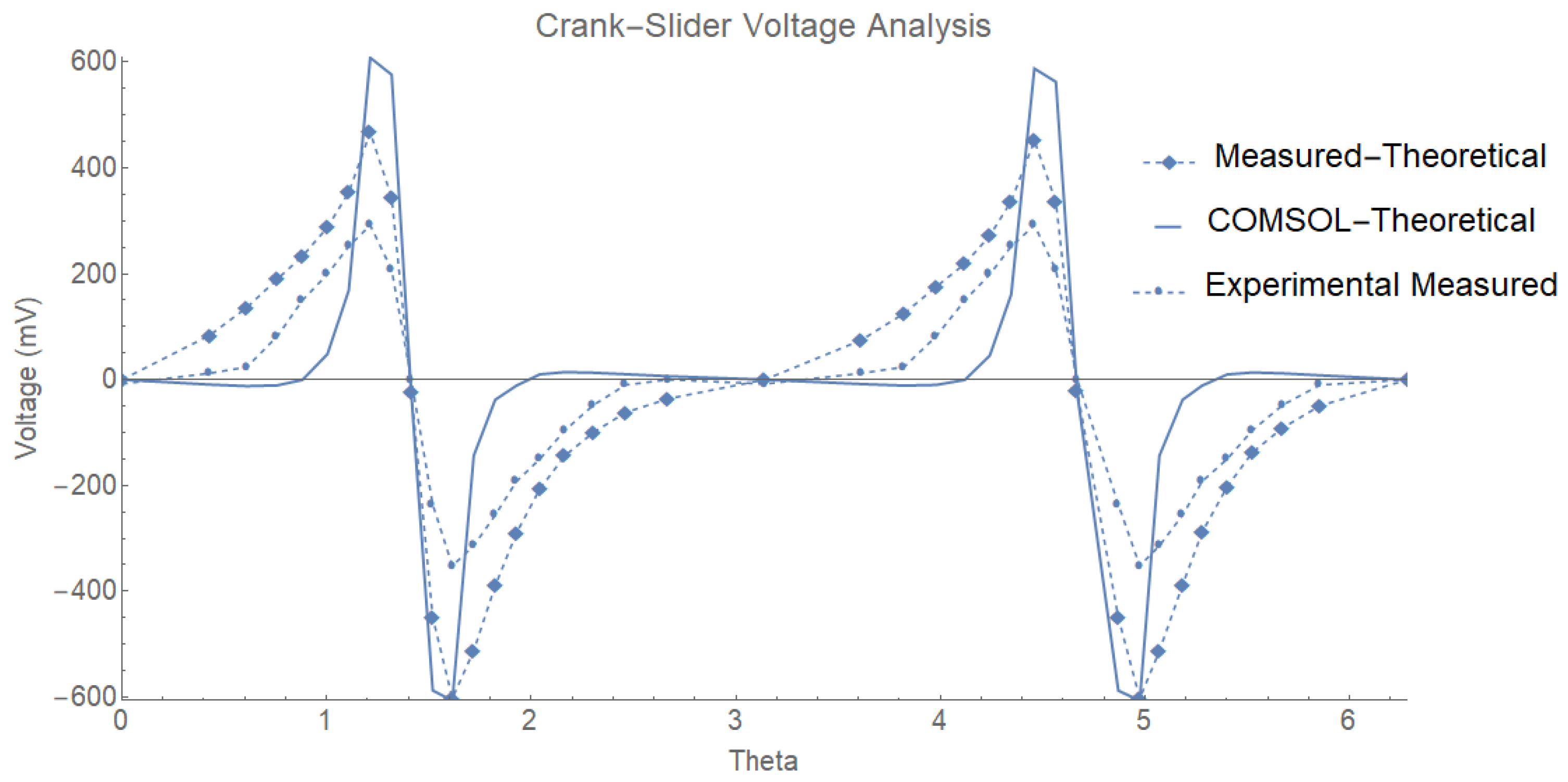
For the crank-slider harvester, the theoretical voltage is evaluated by replacing in Formula (17) with the non-linear kinematic evaluation presented in Formula (8) and Figure 5, resulting in Formula (19). In Figure 12, the theoretical voltage is represented using Formula (19) and both measured and COMSOL values for from Figure 11 in comparison to the actual voltage, measured using a RIGOL DS1054 oscilloscope.
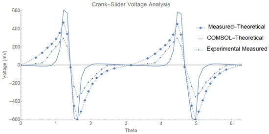
Figure 12.
Sample of open circuit voltage output from the crank-slider harvester at 1 Hz. These data represent a full stroke of the crank starting at 0 and ending at 2, which includes 2 passes through the coil. The first pass occurs from 0 to as the slider extends. The second pass through the coil occurs when the slider retracts as the crank moves from to 2. The measured-theoretical and COMSOL-theoretical values were both evaluated using the data generated from Figure 11. The experimental measured values are the physically measured values generated by a RIGOL oscilloscope for each of the data points. All measurements and predictions were evaluated at 1 Hz.
Although Formula (19) does not include the additional characteristics of the system, namely, the resistance, inductance, parasitic dampening (), or number of turns (N), an electrical power system produces maximum power when coil impedance matches load impedance [36,37]. In Formula (20), the optimal load occurs when the proportionality constant (k) is less than the first term [37].
3. Results and Discussion
3.1. Single Crank-Slider Harvester
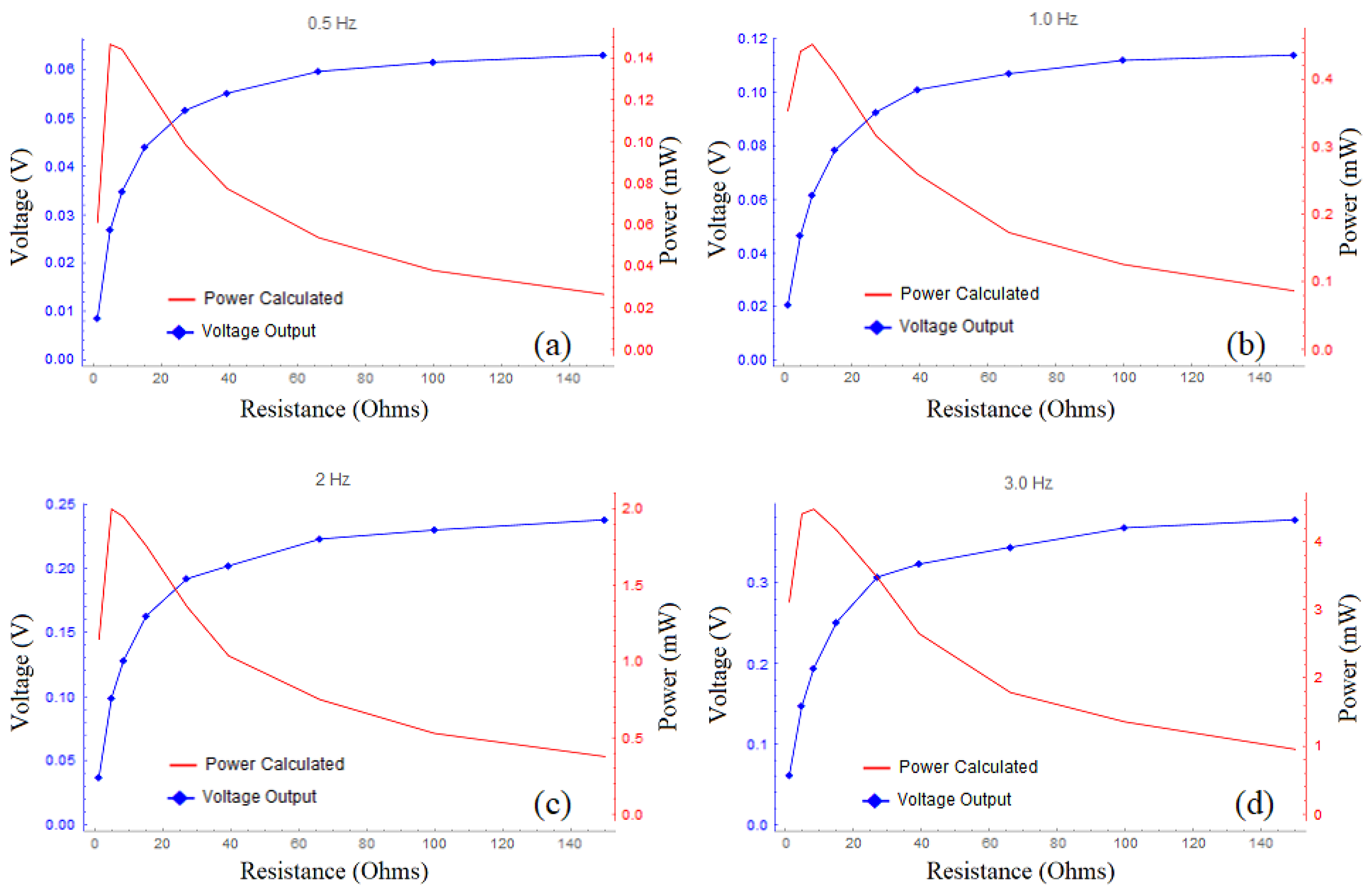
In Figure 12, the actual output of the crank-slider harvester is lower than the theoretical COMSOL and predicted measured values under the outlined conditions. This is typical of many experimental electromagnetic energy harvesters due to a variety of conditions, such as sub-optimal conditions, the exclusion of friction, and parasitic dampening [36,37,38]. The measured experimental voltage and power results for the crank-slider harvester at 0.5, 1, 2, and 3 Hz each with a stroke length of 50 mm are shown in Figure 13. In each of the figures, the optimal power can be observed around 8 , which is close to the measured resistance of the coil used, and this is consistent with what was predicted [36,37]. The maximum power produced for the device at regulated frequencies of 0.5 Hz (30 rpm), 1 Hz (60 rpm), 2 Hz (120 rpm), and 3 Hz (180 rpm) were 0.147, 0.452, 2.00, and 4.48 mW, respectively.
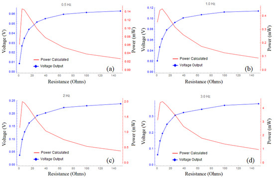
Figure 13.
Voltage and power outputs for the crank-slider harvester at 0.5, 1.0, 2.0, and 3.0 Hz. The devices depicted in each figure (a–d) had a 50 mm stroke length with the coil located at the center of oscillation. The coil had an internal resistance of 8.1 .
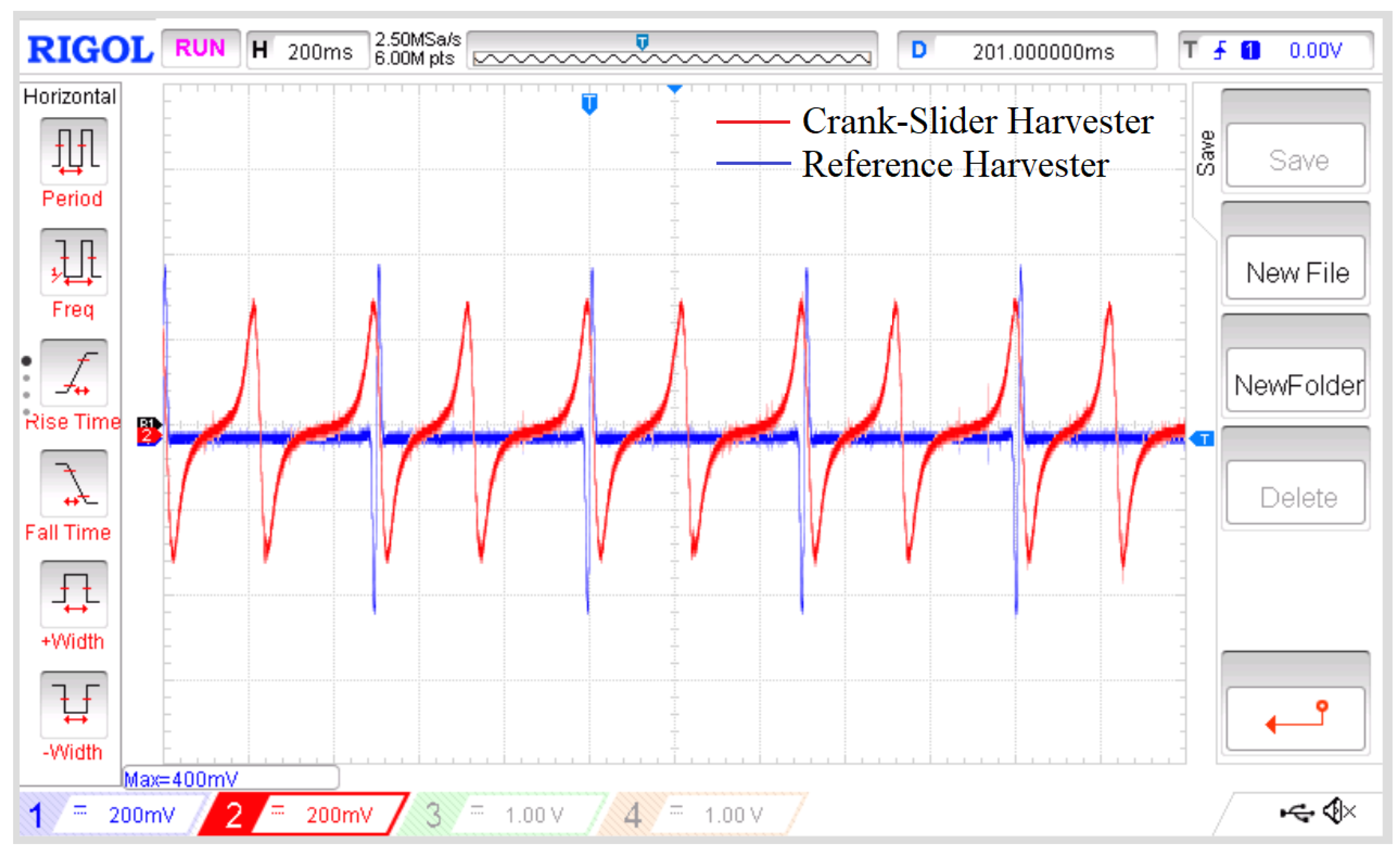
The reference harvester was measured under similar conditions in order to analyze how the crank-slider style of harvester compared to the existing experimental harvester techniques shown in Figure 2 and Figure 3 [22,30,31,32]. The coil size, wire length, , load resistance, and magnet strength of the reference harvester were consistent with the crank-slider during each measurement. The distance R in Figure 8, representing the rotational radius of the rotor’s magnet portion in that style of harvester, was measured at 190 mm. In Figure 14, a sample output of the crank-slider was compared to that of the reference harvester at 3 Hz across a load of 8 to indicate several key factors. First, due to the mechanical nature of the crank-slider mechanism, during each rotation of the driving fan, the stroke cycle of the crank-slider’s magnet passes through its coil twice for every single pass the reference harvester makes across its coil, respectively. Second, the peak voltage and peak-to-peak voltage (), and thus the peak current of the reference harvester were significantly higher than those of the crank-slider harvester, as shown in Figure 15. Finally, in Figure 16, while still under all the same conditions, the crank-slider produced more power than the reference harvester. It could be argued that the reference harvester was not optimized to compete against the crank-slider. Therefore, one could evaluate the data in Figure 16 at a point at which both systems had a similar power output. At 0.5 Hz, the crank-slider produced 0.147 mW, which matched the power output of 0.14 mW that the reference harvester generated at 1.0 Hz. At those chosen points, the crank-slider has 0.176 and the reference harvester has 0.432 at a coil resistance of 8.1 , which equates to an instantaneous current of 21.5 mA and 53.3 mA, respectively. One way to improve the output of any harvester is to use a smaller gauge wire with more turns (N) for the coil. These significantly larger voltage and current spikes on the part of the reference harvester restrict the allowable wire gauges usable for the system. For example, AWG 38 wire has a max current rating of 22.8 mA, which is out of range for use in the reference harvester under these conditions, yet is still usable by the crank-slider design [39].
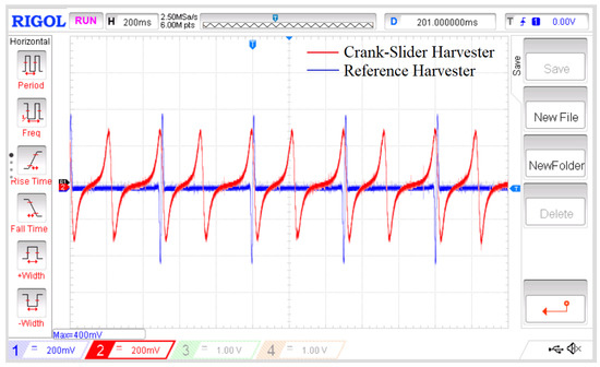
Figure 14.
Output at 2 Hz across a 8.4 resistor for the crank-slider harvester vs. the reference harvester, as measured using an RIGOL DS1054 oscilloscope. The crank-slider oscillates across its coil twice for every single pass of the reference harvester. The reference harvester also has a higher peak voltage and a smaller curve area.
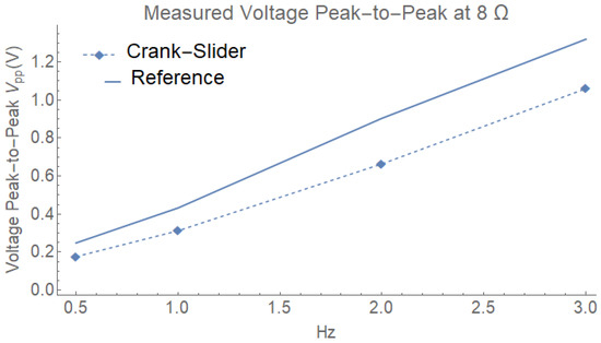
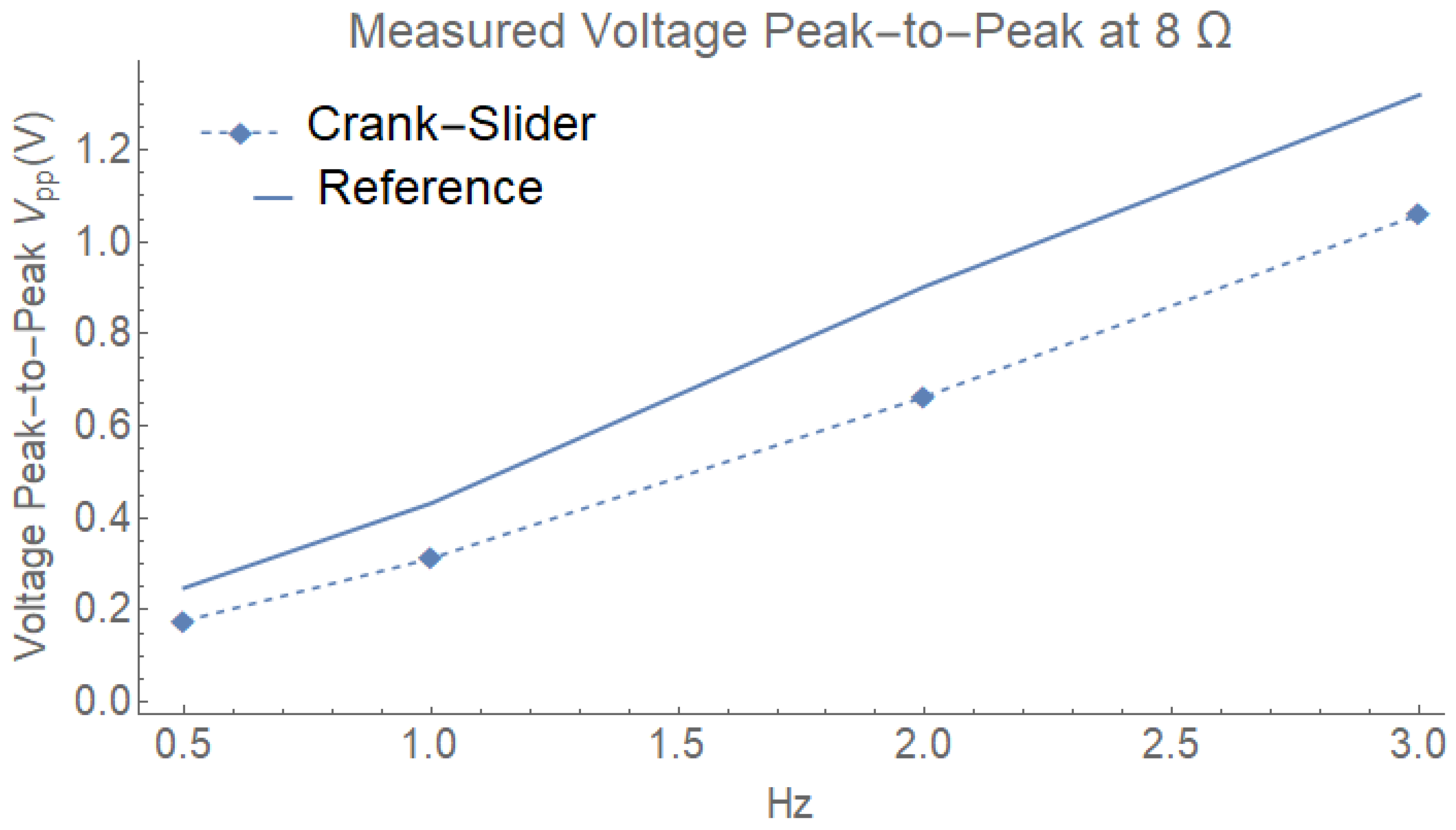
Figure 15.
Measured peak-to-peak voltage demonstrating that the reference harvester had higher values than the crank-slider harvester at 0.5, 1, 2, and 3 Hz with a 8.4 load, signifying that the crank-slider harvester would have a greater range of wire gauge available.
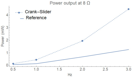
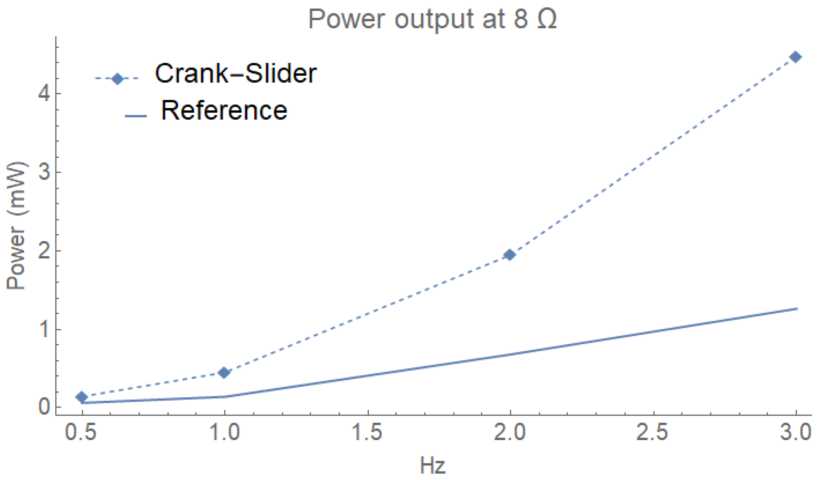
Figure 16.
Power output demonstrating that the reference harvester had a lower power output than the crank-slider harvester at 0.5, 1, 2, and 3 Hz with a 8.4 load.
Finally, due to the previously discussed mass disparity between the very dense neodymium (7000 kg/m) and much less dense connecting materials, such as the ABS plastic (1020 kg/m) used, we only compared the forces encountered only by the action of magnet mass measuredat 23.57 g. This excludes the additional forces of friction, gravity, and resistance, as well as excluding any masses of the material used to connect the magnets to the rest of the system. In the reference case, using Formula (14) at 1 Hz, the outward force was 0.177 N. Using Formula (21) and substituting from Formula (10) to obtain Formula (22), we can evaluate the force of the magnet on the crank-slider. However, in Figure 7, it can be observed that in this case, where l is much greater than r, the max acceleration occurred when r and l were extended to their longest range, which was when equaled zero. The resulting crank-slider harvester maximum force at that moment was 2.35 × N. Based on Formula (14) compared to Formula (22), these 1 Hz force calculations increased equivalently for both models at a value of . Therefore, in all cases of for this experiment, the reference harvester would have significantly larger forces acting upon it. Having dense materials located at critical points such as the tips of the blades on the reference harvester, similarly to those presented in Figure 2 and Figure 3, would be problematic considering the fact that the majority of failures for wind turbines are due to mass imbalances [40].
3.2. V-Twin Harvester Utilizing Two Crank-Slider Mechanisms
Figure 17 depicts a combination of two crank-slider harvesters in a V-twin formation similar to common designs used in motorcycle engines. Due to the magnets being positioned at a large distance relative the drop in magnetic field strength, it is assumed that neither magnet interferes with the other’s coil when referring to in Formula (1). This configuration allows for several methods of analyzing the output of the system by re-configuring the wiring of the two load resistors and two coils according to the wiring diagram column in Table 1.

Figure 17.
Front (a) and back (b) V-twin harvester formation.

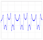
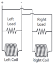
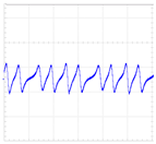
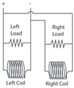
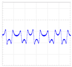
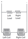
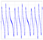
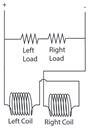
Table 1.
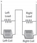
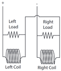
Output of V-twin harvesters in both series and parallel configuration at 2 Hz. (a) each cylinder and its respective load resistance of 8.2 were wired in series as units. The resulting total load resistance was 16.4 . (b) the output leads of the right cylinder were interchanged from the system shown inimage (a). (c) each cylinder and its respective load resistance of 8.2 in parallel as units. (d) the output leads of the right cylinder were switched from the system shown in image (c). In (e), each cylinder was wired in series and both loads were wired in series; however, both cylinders were kept in parallel with both loads. In (f), the output leads of the right cylinder were switched with those from the system shown in image (e).
This proposed device is simple in design, easily transported, and could be readily re-manufactured with most components being 3D-printed. In addition, the V-twin has the potential to be used in various remote, hazardous, or emergency locations or situations. This design has room to be improved by adding more crank-slider harvesters to the V-twin design, including a rectifier and an energy storage system, or improving the coil structure by using a smaller-gauge wire with more turns.
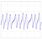
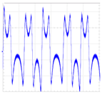
In Table 1, each measurement was made at 2 Hz for all configurations. In each configuration, the main difference when swapping the leads was observed when using the in- and out-of-sync patterns for the output. For example, in the first configuration image (a) under the oscilloscope output column in Table 1, the output from the V-twin system was reminiscent of a typical sine wave output generated by the typical linear oscillating electromagnetic harvester akin to that in Figure 1. However, swapping the leads, as in image (b), resulted in an interesting output that showed improved performance across all configurations.
In the first configuration, which includes images (a) and (b) from Table 1, both cylinders and their loads were wired together in series with the other cylinder. In (b), the leads from the right cylinder were swapped with those from (a). In the second configuration, which includes images (c) and (d), each cylinder along with its load were wired in parallel with the other cylinder and load. These four configurations performed poorly, with the power output of both harvesters under-performing when having only a single harvester in operation. The highest power was generated in the third configuration, in which the system was wired with the coils in series with each other, and the loads in series but in parallel with the coils as shown in (e) and (f). Considering that a single crank-slider harvester under these conditions generated 2 mW, then it would be reasonable to assume that the standard for two would be 4 mW due to series stacking on phase output. However, as shown in image (f), with an output of 7.30 mW, this configuration produced 45.2% more power than what would be expected by the standard. Conversely, having the system in parallel reduced the overall output, with image (c) showing the poorest performance due to parallel stacking.
A residential fan was used to supply input wind energy to the device using three standard speeds—3.2, 3.4, and 4.1 m/s—measured at 65 mm from the surface using an XRCLIF-818 Anemometer. We found that the threshold speed fell between 3.2 and 3.4 m/s. At 3.2 m/s, the V-twin harvester would require a small force to overcome initial resisting forces. However, at 3.4 m/s the system could start harvesting with only the residential fan acting upon it.
Table 2, summarizes the performances of comparable style and size for the harvesting devices and indicates that the proposed V-twin harvesters displayed the highest wind speed to power conversion. As shown in Table 2, the V-twin system presented in this paper used the optimal set up shown in image (f) in Table 1 across a load of 16.3 and had measurements taken at 3.4 and 4.1 m/s. The small-scale windmill design by Myers et al. [6] utilizes wind energy harvesting in combination with piezoelectric bimorph transducers. We compared the highest readings (from lab results) listed in a study on highway bridge vibrations by Peigney and Siegert [41].Both vehicle-mounted harvesters developed by Li et al. utilize wind harvesting to excite a piezoelectric device [42]. In their designs, tge difference between FPEH and EVEH was that of a ’fluttering’ device versus a linear electromagnetic harvester. A triboelectric-hybrid study by Ye et al. ubvikved multiple devices and configurations; however, the highest performance was observed for the FB-EMG design that used a rotor and stator to harvest wind energy [43]. The outdoor IoT harvester designed by Fang et al. is similar to our reference harvester, utilizing rotating magnets at a large radius to harvest wind [30]. For the galloping wind harvester studied by Wang et al., the SHPTWEH had the highest performance, out of the several versions that were developed [44]. Cao et al. developed a Canyon Bridge system that used a combination of both piezoelectric and electromagnetic harvesters in their design [45].
Table 2.
Harvester wind speed testing comparison.
4. Conclusions
Based on the analysis of the crank-slider design presented in the Section 3, in this study we designed and fabricated a novel V-twin-shaped energy harvester to convert rotational energy from wind into electrical energy using inductive energy harvesting. From the single magnet and coil crank-slider system operating at a regulated 2 Hz across an optimized load of 8.4 , the average power generated was 2.0 mW. In order to improve the power output at low frequency, a V-twin harvester was designed. This improved design combined two of the crank-slider designs into a single harvester output and it was evaluated under several operating conditions. We experimentally observed that the V-twin system wired in a series configuration produced 7.30 mW at the same regulated frequency of 2 Hz. The results demonstrate an increase in performance over two crank-slider harvesters of 45.2%. We also found that the V-twin harvester generated 27.0 and 42.2 mW of power at wind speeds of 3.4 and 4.1 m/s for the optimized configuration, i.e., series-series electrical connections for coils and loads.
The results show that this is a promising solution for the harvesting of low-to-high-speed wind energy as a method of powering small-scale electronic devices such as cell phones or smart devices. We believe that the energy harvester design proposed here is much cleaner, with less interface, than those of commercially available wind energy harvesters used for generating electricity on a large scale.
Author Contributions
Writing—original draft, J.F. and V.B. All authors have read and agreed to the published version of the manuscript.
Funding
This research received no external funding.
Conflicts of Interest
The authors declare no conflict of interest.
References
- U.S. EIA (U.S. Energy Information Administration). Independent Statistics and Analysis; U.S. EIA: Washington, DC, USA, 2022.
- BP Plc. bp Statistical Review of World Energy 2020; Addison-Wesley: London, UK, 2020. [Google Scholar]
- Kiziroglou, M.; Yeatman, E. 17—Materials and techniques for energy harvesting. In Functional Materials for Sustainable Energy Applications; Kilner, J.A., Skinner, S.J., Irvine, S.J., Edwards, P.P., Eds.; Woodhead Publishing Series in Energy; Woodhead Publishing: Cambridge, UK, 2012; pp. 541–572. [Google Scholar] [CrossRef]
- Khan, F.U.; Ahmad, I. Review of Energy Harvesters Utilizing Bridge Vibrations. Shock Vib. 2016, 2016, 1340402. [Google Scholar] [CrossRef]
- Roundy, S. On the Effectiveness of Vibration-based Energy Harvesting. J. Intell. Mater. Syst. Struct. 2005, 16, 809–823. [Google Scholar] [CrossRef]
- Myers, R.; Vickers, M.; Kim, H.; Priya, S. Small scale windmill. Appl. Phys. Lett. 2007, 90, 054106. [Google Scholar] [CrossRef]
- Dutta, M.; Shrimoyee, P. Footstep voltage generator using piezo-electric transducers. Int. J. Sci. Eng. Res. 2017, 8, 117–120. [Google Scholar]
- Crovetto, A.; Wang, F.; Hansen, O. Modeling and Optimization of an Electrostatic Energy Harvesting Device. J. Microelectromech. Syst. 2014, 23, 1141–1155. [Google Scholar] [CrossRef]
- Annapureddy, V.; Palneedi, H.; Hwang, G.T.; Peddigari, M.; Jeong, D.Y.; Yoon, W.H.; Kim, K.H.; Ryu, J. Magnetic energy harvesting with magnetoelectrics: An emerging technology for self-powered autonomous systems. Sustain. Energy Fuels 2017, 1, 2039–2052. [Google Scholar] [CrossRef]
- Chen, W.T.; Gurdal, A.E.; Tuncdemir, S.; Gambal, J.; Chen, X.M.; Randall, C.A. Introducing an extremely high output power and high temperature piezoelectric bimorph energy harvester technology based on the ferroelectric system Bi(Me)O3-PbTiO3. J. Appl. Phys. 2020, 128, 144102. [Google Scholar] [CrossRef]
- Dinulovic, D.; Brooks, M.; Haug, M.; Petrovic, T. Rotational Electromagnetic Energy Harvesting System. Phys. Procedia 2015, 75, 1244–1251. [Google Scholar] [CrossRef]
- Luong, H.T.; Goo, N.S. Use of a magnetic force exciter to vibrate a piezocomposite generating element in a small-scale windmill. Smart Mater. Struct. 2012, 21, 025017. [Google Scholar] [CrossRef]
- Wang, X.; Pan, C.L.; Liu, Y.B.; Feng, Z.H. Electromagnetic resonant cavity wind energy harvester with optimized reed design and effective magnetic loop. Sens. Actuators A Phys. 2014, 205, 63–71. [Google Scholar] [CrossRef]
- Chen, J. Barrel of Oil Equivalent (BOE). 2020. Available online: https://www.investopedia.com/terms/b/barrelofoilequivalent.asp#:\protect\T1\textdollar\sim\protect\T1\textdollar:text=%20There%20are%2042%20gallons%20(approximately,have%20slightly%20different%20energy%20%20equivalents (accessed on 27 July 2022).
- Cepnik, C.; Lausecker, R.; Wallrabe, U. Review on electrodynamic energy harvesters—A classification approach. Micromachines 2013, 4, 168–196. [Google Scholar] [CrossRef]
- Shi, B.; Li, Z.; Fan, Y. Implantable energy-harvesting devices. Adv. Mater. 2018, 30, 1801511. [Google Scholar] [CrossRef] [PubMed]
- Michaud, S.; Schneider, A.; Bertrand, R.; Lamon, P.; Siegwart, R.; Winnendael, M.v.; Schiele, A. SOLERO: Solar powered exploration rover. In Proceedings of the 7th ESA Workshop on Advanced Space Technologies for Robotics and Automation (ASTRA), Noordwijk, The Netherlands, 19–21 November 2002; ETH-Zürich: Zurich, Switzerland, 2002. [Google Scholar]
- Lamarre, O.; Kelly, J. Overcoming the challenges of solar rover autonomy: Enabling long-duration planetary navigation. arXiv 2018, arXiv:1805.05451. [Google Scholar]
- Landis, G.A. Exploring mars with solar-powered rovers. In Proceedings of the Conference Record of the Thirty-First IEEE Photovoltaic Specialists Conference, Lake Buena Vista, FL, USA, 3–7 January 2005; IEEE: New York, NY, USA, 2005; pp. 858–861. [Google Scholar]
- Zhao, L.C.; Zou, H.X.; Yan, G.; Liu, F.R.; Tan, T.; Wei, K.X.; Zhang, W.M. Magnetic coupling and flextensional amplification mechanisms for high-robustness ambient wind energy harvesting. Energy Convers. Manag. 2019, 201, 112166. [Google Scholar] [CrossRef]
- Izadgoshasb, I.; Lim, Y.Y.; Vasquez Padilla, R.; Sedighi, M.; Novak, J.P. Performance enhancement of a multiresonant piezoelectric energy harvester for low frequency vibrations. Energies 2019, 12, 2770. [Google Scholar] [CrossRef]
- Fan, K.; Qu, H.; Wu, Y.; Wen, T.; Wang, F. Design and development of a rotational energy harvester for ultralow frequency vibrations and irregular human motions. Renew. Energy 2020, 156, 1028–1039. [Google Scholar] [CrossRef]
- Li, X.; Meng, J.; Yang, C.; Zhang, H.; Zhang, L.; Song, R. A magnetically coupled electromagnetic energy harvester with low operating frequency for human body kinetic energy. Micromachines 2021, 12, 1300. [Google Scholar] [CrossRef] [PubMed]
- Tang, X.; Zuo, L. Simulation and experiment validation of simultaneous vibration control and energy harvesting from buildings using tuned mass dampers. In Proceedings of the 2011 American Control Conference, San Francisco, CA, USA, 29 June–1 July 2011; IEEE: New York, NY, USA, 2011; pp. 3134–3139. [Google Scholar]
- Sato, M.; Takemura, T.; Mizuno, T. Voltage Improvement of a Swing-Magnet-Type Generator for Harvesting Bicycle Vibrations. Energies 2022, 15, 4630. [Google Scholar] [CrossRef]
- National Geographic Society (NGS). Wind Energy; NGS: Washington, DC, USA, 2022. [Google Scholar]
- Contreras Montoya, L.T.; Hayyani, M.Y.; Issa, M.; Ilinca, A.; Ibrahim, H.; Rezkallah, M. 8—Wind power plant planning and modeling. In Hybrid Renewable Energy Systems and Microgrids; Kabalci, E., Ed.; Academic Press: Cambridge, MA, USA, 2021; pp. 259–312. [Google Scholar] [CrossRef]
- Hyams, M. Wind energy in the built environment. In Metropolitan Sustainability; Elsevier: Amsterdam, The Netherlands, 2012; pp. 457–499. [Google Scholar]
- Appadurai, M.; Raj, E.F.I. Finite Element Analysis of Composite Wind Turbine Blades. In Proceedings of the 2021 7th International Conference on Electrical Energy Systems (ICEES), Virtual, 11–13 February 2021; pp. 585–589. [Google Scholar] [CrossRef]
- Fang, Y.; Tang, T.; Li, Y.; Hou, C.; Wen, F.; Yang, Z.; Chen, T.; Sun, L.; Liu, H.; Lee, C. A high-performance triboelectric-electromagnetic hybrid wind energy harvester based on rotational tapered rollers aiming at outdoor IoT applications. iScience 2021, 24, 102300. [Google Scholar] [CrossRef]
- Pozo, B.; Gárate, J.; Araujo, J.; Ferreiro, S. Energy Harvesting Technologies and Equivalent Electronic Structural Models—Review. Electronics 2019, 8, 486. [Google Scholar] [CrossRef]
- Pozo, B.; Araujo, J.; Zessin, H.; Mateu, L.; Gárate, J.; Spies, P. Mini Wind Harvester and a Low Power Three-Phase AC/DC Converter to Power IoT Devices: Analysis, Simulation, Test and Design. Appl. Sci. 2020, 10, 6347. [Google Scholar] [CrossRef]
- Narolia, T.; Gupta, V.; Parinov, I. Design and analysis of a shear mode piezoelectric energy harvester for rotational motion system. J. Adv. Dielectr. 2020, 10, 2050008. [Google Scholar] [CrossRef]
- Shigley, J.E. Series in Mechanical Engineering; McGraw Hill Book Company Inc.: New York, NY, USA, 1961. [Google Scholar]
- McCaslin, S.; Brown, F. Slider and Crank Mechanism. 2010. Available online: https://demonstrations.wolfram.com/SliderAndCrankMechanism/ (accessed on 27 July 2022).
- Bedekar, V.; Oliver, J.; Priya, S. Pen harvester for powering a pulse rate sensor. J. Phys. D Appl. Phys. 2009, 42, 105105. [Google Scholar] [CrossRef]
- Saha, C.R.; O’Donnell, T.; Loder, H.; Beeby, S.; Tudor, J. Optimization of an electromagnetic energy harvesting device. IEEE Trans. Magn. 2006, 42, 3509–3511. [Google Scholar] [CrossRef]
- Xu, Z.; Shan, X.; Chen, D.; Xie, T. A novel tunable multi-frequency hybrid vibration energy harvester using piezoelectric and electromagnetic conversion mechanisms. Appl. Sci. 2016, 6, 10. [Google Scholar] [CrossRef]
- Teja, R. Wire Gauge Chart | American Wire Gauge (AWG) Wire Size Chart. 2021. Available online: https://www.electronicshub.org/wire-gauge-chart/ (accessed on 27 July 2022).
- Chen, J.; Hu, W.; Cao, D.; Zhang, B.; Huang, Q.; Chen, Z.; Blaabjerg, F. An imbalance fault detection algorithm for variable-speed wind turbines: A deep learning approach. Energies 2019, 12, 2764. [Google Scholar] [CrossRef]
- Peigney, M.; Siegert, D. Low-frequency electromagnetic energy harvesting from highway bridge vibrations. J. Bridge Eng. 2020, 25, 04020056. [Google Scholar] [CrossRef]
- Li, X.; Li, Z.; Bi, C.; Liu, B.; Su, Y. Study on wind energy harvesting effect of a vehicle-mounted piezo-electromagnetic hybrid energy harvester. IEEE Access 2020, 8, 167631–167646. [Google Scholar] [CrossRef]
- Ye, C.; Dong, K.; An, J.; Yi, J.; Peng, X.; Ning, C.; Wang, Z.L. A triboelectric–electromagnetic hybrid nanogenerator with broadband working range for wind energy harvesting and a self-powered wind speed sensor. ACS Energy Lett. 2021, 6, 1443–1452. [Google Scholar] [CrossRef]
- Wang, Q.; Zou, H.X.; Zhao, L.C.; Li, M.; Wei, K.X.; Huang, L.P.; Zhang, W.M. A synergetic hybrid mechanism of piezoelectric and triboelectric for galloping wind energy harvesting. Appl. Phys. Lett. 2020, 117, 043902. [Google Scholar] [CrossRef]
- Cao, H.; Wu, X.; Wu, H.; Pan, Y.; Luo, D.; Azam, A.; Zhang, Z. A Hybrid Self-Powered System Based on Wind Energy Harvesting for Low-Power Sensors on Canyon Bridges. Int. J. Precis. Eng. Manuf. -Green Technol. 2022. [Google Scholar] [CrossRef]


Publisher’s Note: MDPI stays neutral with regard to jurisdictional claims in published maps and institutional affiliations. |
© 2022 by the authors. Licensee MDPI, Basel, Switzerland. This article is an open access article distributed under the terms and conditions of the Creative Commons Attribution (CC BY) license (https://creativecommons.org/licenses/by/4.0/).