Review

A Comprehensive Review on Multilevel Inverters for Grid-Tied System Applications

1
School of Electrical and Electronic Engineering, Universiti Sains Malaysia (USM), Nibong Tebal 14300, Penang, Malaysia
2
Department of Information Engineering, University of Brescia, 25121 Brescia, Italy
3
Department of Electrical and Electronics Engineering, Nisantasi University, Istanbul 34467, Turkey
4
British Malaysian Institute, Universiti Kuala Lumpur, Kuala Lumpur 50250, Malaysia
*
Authors to whom correspondence should be addressed.
Energies 2022, 15(17), 6315; https://doi.org/10.3390/en15176315
Submission received: 30 July 2022 / Revised: 22 August 2022 / Accepted: 23 August 2022 / Published: 29 August 2022

Abstract

:
Multi-level inverters (MLIs) have been widely used in recent years due to their various advantages in industrial and grid-connected applications. Traditional MLI topologies are being hampered by the rapid surge of renewable energy systems (RES) as a result of performance difficulties such as poor power reliability, an economically unviable structure, and a lack of efficiency. These difficulties are due to the traditional MLI topologies’ inability to keep up with the increasing demand for RES. Because of concerns about performance and limitations posed by classic MLI topologies, researchers have found themselves driven to the idea of building innovative hybrid MLI topologies. This study provides a comprehensive analysis of multilevel inverter systems that are wired into the main power supply. Grid-connected inverter types and their configurations are discussed in depth in this review. Diverse multi-level inverter topologies, as well as the different approaches, are divided into various categories and discussed in depth. Additionally, a number of control reference frames for inverters were brought forward for discussion. Furthermore, different inverter control strategies were investigated, followed by a tabular summary of recent developments in the inverter-related literature for the convenience of the readers. Moreover, the recently proposed grid-connected multi-level inverter systems were discussed including their findings and innovations. In conclusion, a brief description of the study’s scope was offered and research directions for future studies were provided.

1. Introduction

Electricity generated by wind and solar power is now connected to the power grid in the contemporary period to allow for more efficient alternative and renewable energy sources [1]. It is not possible for loads or the system to directly use the electricity generated by renewable energy sources, hence, MLIs are specifically used as an interface between various electrical power equipment (“DC-AC” inverters) and as converters (“DC-DC”). In 1975, the very first MLI application was made starting with three-level converters and then enhancing progressively to various MLIs topologies within these years. For MLIs implementations on grid-tied systems, a purely sinusoidal waveform may be sent to the grid instead of a current/voltage that has fewer harmonics; this would be another option. The frequencies of the grid must coincide with the frequency of the implanted signals [2]. To generate sinusoidal three-phase current and voltage with fewer harmonics, an MLI setup with an LC filter is typically utilized. The original three-level inverters were the first choice in industry for connecting renewable energy sources to power grid. However, this type of inverters has several drawbacks, that necessitates further inverter topology modifications. Given that the inverters generate a multi-stepped waves output, there is a possibility that the harmonic characteristic will be improved. First, they need devices with high power ratings to be used in high power applications. This increases the cost of the inverter and gives a high level of switching losses. Second, the output of conventional inverters is between two level (i.e., 0 V and Vdc) that generates a poor-quality waveform with huge amounts of harmonics. To overcome these drawbacks and limitations, MLIs have been introduced and widely utilized by the industry [3]. MLIs have several advantages compared to conventional inverters in terms of harmonic characteristics, operational efficiency, less strain on MLIs under load, and decreased electromagnetic interference (EMI) [4]. The DC input voltage required by the MLIs may be supplied by a variety of renewable energy sources, such as solar arrays with DC-DC converters, inductive synchronous/generators, generator-fed windmills, rectification designs, and fuel cells with DC-DC converters [1]. The waveform may be employed in a number of methods, including, but not limited to hysteresis current control and multi-level H-bridge spiraled inverters to optimize the harmonics profiles of the voltages and the output current before it is connected to the grid.
Currently, there are a lot of studies on MLIs in order to enhance their performances by modifying MLIs topology. In [5], the research shows the modified MLIs topology produced seven-level voltage waveform with low harmonic contents in photovoltaic (PV) applications. New MLI configuration with reduced switches had been studied by [6] which did not require any extra components such as inductors and capacitors in the system. Due to its fault-tolerant and modular capabilities, higher voltage levels and a suitable sinusoidal voltage waveform were generated. In addition to that, [7] has reviewed recent proposed MLIs with fewer components according to the comparative factors, selection of components, and their suitability and availability. Lastly, in order to enhance the flexibility and efficiency of power systems as well as maximize power extraction and efficiency, references [8,9] have proposed the design of modular cascaded H-bridge multilevel inverter (CHBMLI) in single or three phase grid-connected applications.
According to bibliometric study based on Scopus, there were total 449 papers relating with MLIs for grid connected systems were published on various journals for the past 10 years since year 2012 as shown in Figure 1. The number of published papers had shown a great increment from the year 2012 to year 2019. Starting from year 2020, the number of published papers had shown an insignificant drop until the year 2022. In addition, most studies on MLIs are mainly concentrating on gate driver circuits, switch count reduction, power quality and fault tolerance improvement on DC supplies, and cost-effectiveness for grid-connected systems. On the other hand, Table 1 shows the comparison of a number of published articles and citations that relating with MLs implementation in grid-connected systems among the countries from the year 2012 to year 2022 based on Scopus. There are only 19 countries that published more than 10 related articles for the past 10 years. India has the highest publications with an outstanding number, 160 among the listed countries in the past 10 years. However, India obtained the second highest number of citations, which is 1520 while Canada has the highest citations which obtained 1848 citations with only 31 published articles since year 2012. Next, China is listed as the third highest number for both publications and citations which are 72 numbers and 1275 numbers, respectively, among the countries.
This paper presents a comprehensive review of multilevel inverter systems, especially those that are wired into the main power supply. Grid-connected inverter types and their configurations are discussed in depth in this review. Additionally, diverse multi-level inverter topologies, as well as the different modulation and control approaches are introduced in depth. Furthermore, recent developments in the inverter-related literature and future directions are provided in this work. The rest of this paper is organized as follows. Section 2 provides a detailed review of the MLI systems and introduces their different configurations. The modulation techniques (MTs) and the different control strategies for MLI systems are presented in Section 3 and Section 4, respectively. Section 5 reviews the recently developed MLI systems and discusses their innovations and findings. Finally, the research directions for future studies and the summary of the paper findings are given in Section 6 and Section 7, respectively.

2. Multi-Level Inverters (MLIs)

MLIs are increasingly being integrated into systems with low levels of electronic radiation and harmonic distortion due to their capacity to fulfill certain criteria for power rating and electric power quality. The traditional two-level inverters that employ pulse with modulations (PWM) are a far cry from this new technology. With a constant switching frequency, an MLI offers a number of distinct advantages [10]. Hence, MLIs are now being investigated as a potential commercial solution for dynamic performance-demanding applications and high-power quality. The power range for these applications is anywhere from one megawatt to thirty megawatts [11]. Since they have larger voltages and can create lower total harmonic distortion(THD) output voltage waveforms with restricted device ratings, MLIs are thus perfect for utilization in high voltage applications [12]. A multilayer converter system may interact with sustainable energy sources such as wind, fuel cells, and PV cells in a variety of ways [13]. The PWM of MLIs is primarily controlled by the kind of control algorithm used to define their applications, efficiency power ratings, and operation [14]. Over the last several decades, a number of researchers have suggested different MLI topologies [15,16]. There are two major groupings for MLIs depending on the number of DC sources in their topologies. The most utilized and widely implemented topologies in the commercial sector at the present time are the fly capacitor, neutral-point clamped (NPC), and cascaded H-bridge topologies [17,18].

2.1. Grid-Tied Multi-Level Inverters

MLIs can be tied to the grid in two different ways as presented in Figure 2.

2.1.1. Single-Stage Inverter

Multiple functions are performed by the inverter’s single-stage design, including monitoring the maximum power point (MPP), amplification of voltage, and regulation of injected grid currents [19]. As per the equation shown beneath, the single-stage inverter’s design accommodates the double peak power.
P g r i d = 2 P g r i d s i n 2 ( ω g r i d t )
where ωgrid is the grid frequency and Pgrid is the peak grid power.
The use of line-frequency transformers that operates at lower frequencies in a single-stage inverter not only contributes to a large increase in the inverter’s overall weight but also results in a two percent decrease in the device’s peak efficiency [20]. On the other hand, the best practical, economical, and lightweight converter design uses a high-frequency transformer or is transformer-less. The line frequency transformers are being replaced more often now. There are other inverter topologies discussed here [21,22,23,24,25,26,27,28,29,30,31,32,33,34,35,36] with certain merits and demerits. In a single-stage inverter, the DC-AC conversion and maximum power point tracking (MPPT) are performed using only a single stage without the need for any additional DC-DC converter. Within those systems, the energy storage component is typically an inductor or a high-frequency transformer that also serves as an energy storage and isolation device. The absence of the line frequency transformer is one of the buck–boost single-stage inverter’s important features. However, single-stage inverters usually have a narrow DC input voltage range, bad power quality, and a limited power capacity [37]. Additionally, when the power capacity goes up, the current stresses on the devices that change power go up. Because of this, single-stage inverters are not used in situations that demand wide variation in voltages, good power quality, and a lot of distribution size. So, inverters with more than one stage are used in these situations.

2.1.2. Multiple Stage Inverter

A multiple-stage inverter is one that has more than one step of power processing. While the first stage (including occasionally the stages that follow it) is responsible for boosting the voltage, this inverter’s final stage is responsible for converting DC-AC and sometimes galvanically separating the two currents [31]. Because there is no transformer utilized in this situation, the converter’s input DC voltage range is quite small, and it is of the non-isolated kind [31]. Other buck–boost inverters use a high-frequency converter that operates at a low DC voltage. The second-stage inverter transforms the first stage’s corrected voltage into a full-wave sinusoidal waveform for each of the aforementioned topologies at the line-frequency [31]. Multiple stage inverters can be divided into several different groups, and these may be broken down into several categories based on the following details:

2.1.3. Comparison of Advantages and Disadvantages between Single-Stage and Multi-Stage Inverters

Table 2 shows the advantages and disadvantages of single-stage and multi-stage inverters with different connection structures, respectively.

2.2. Classification of Multi-Level Inverters

The classification of multi-level inverters that are connected to the grid is as follows.

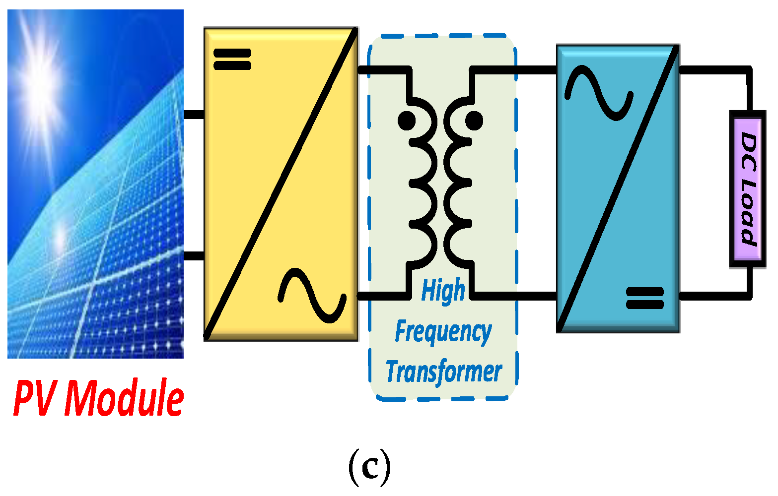
2.2.1. Classification Based on Transformers

Grid-connected PV inverter topologies typically fall into one of two kinds depending on the transformer utilized-transformer-based topologies and transformer-less topologies [46]. Galvanic isolation between the DC source and the utility grid is achieved in the inverters by using line-frequency transformers. The isolating transformer helps to address the issue of DC injection into the electric grid via the DC connection. As a result of its weight and bulk, among the inverter components, its line-frequency transformer is considered the most troublesome. Transformers in inverters and DC-DC converters may be utilized to deal with this problem; doing so minimizes the system’s size and weight, which lowers the system’s total cost. To take this into account, Figure 3 presents a few inverter topologies.
Compared to transformer topologies, the transformer-less inverter is more affordable with improved efficiency. However, they need additional circuitry to handle the DC injection issue. The lack of galvanic isolation between the utility grid and the DC generating unit is another issue with transformer-less topologies. Additionally, it might result in voltage changes between the DC source and the ground depending on the inverter circuit. The creation of electromagnetic interference, which is brought on by voltage variations, is another issue with transformer-less inverters. Although transformer-less topologies have a minimal and non-existent electromagnetic intrusion as claimed by many research investigations [32,33,34], there are, however, several rules that must be followed while using transformer-less grid-connected inverters (over 10 A).

2.2.2. Classification Based on Topologies

The total cost of grid-connected renewable energy systems has gone down because of improvements in the grid-connected inverter technology [40]. There are several benefits of using multidimensional grid-connected inverters instead of two-level inverters. The output terminal of the multilevel inverters produces an AC voltage that has many stairway voltage levels. The multilevel inverter’s staircase sinusoidal waveform closely resembles a real, pure sinusoidal wave and has little overall harmonic distortion. As a result, there is less harmonic distortion and less need for a filter. Because PV arrays are made up of separate modules, it is easy to make different DC voltage levels; as a result, multilevel topologies are primarily appropriate for PV systems. The concept of the multilevel converter has been discussed since 1975 [47], and a three-level converter is credited with coining the name multilevel [32]. As a result, researchers [31,48,49] have created a few multilayer converter typologies as described in the following subsection.
  • Half-bridge diode clamped inverters
Single-phase PV systems that link to the grid without the need for a transformer rely on three-level inverters with half-bridge diode clamping as shown schematically in Figure 4 [48]. The output terminal of both inverters will receive a positive voltage if both valves S1 and S2 are switched on at any time. To achieve a negative voltage, S3 and S4 should be turned on at the same time, and S2 and S3 should be activated simultaneously. If the plan is to obtain electricity from the DC bus, a higher voltage than the utility grid voltage will need to flow from the DC system to a utility grid. This inverter’s design eliminates capacitive earth current and electromagnetic interference by grounding the DC source’s middle [49].
  • Full-bridge single-leg clamped inverters
Full-bridge inverters for household PV systems are shown in Figure 5. Additionally, the bidirectional switches, S1 and S2, as well as the diodes, D1 and D2 are added to the full-bridge switch S6, S5, and S4 [50]. As a result, the current going to and from the DC bus’s middle may be properly controlled. With this design, a transformer-free PV system’s inverter must be at least 1.5 kW in size [34].
  • Cascaded inverters
Figure 6 [52] shows a cascaded inverter that is to be solar panels connected to the grid; the system requires no transformer to change DC to AC. To expand the number of voltage levels, this design links the AC outputs of two full-bridge arrangements in series [53]; this is because the AC voltage coming out of each bridge can be one of three different levels. Hence, an AC output voltage with five levels is made. The cascaded inverter’s scalable and modular nature is its primary benefit as it could be expanded to accomplish equal stages simply by dropping the original three-level modules. According to FFF, a DC system without even a transformer may be constructed by connecting more than two full bridge topologies in series. This system requires just a small quantity of DC voltage on the inverting input (for example, 40 V per bridge) [24]. Cascaded inverters are also discussed in [54,55] for high-power applications.
  • Switching inverters
Inverters may also be classified according to the sort of switching used. The inverters are classified in this instance based on the kind of switching used rather than the number of power stages. There are two kinds of inverters: soft-switching and hard inverters. There may be one or more power stages in both hard- and soft-switching inverters. Grid-connected DC inverters with power density and high, high efficiency, as well as higher performance are made using soft switching technology.
Acute variations in switch currents and voltages produce serious EMI difficulties and switching losses, particularly in high-frequency switching inverters [56,57]. Hard swapping is when devices are turned on and off quickly and at random times, which can cause a number of problems during the switching process. Power electronic equipment’s stray inductances and parasitic capacitances cause substantial current or voltage spikes amid sudden switching transients. The soft-switching design combines standard hard-switching PWM circuits with auxiliary diodes, passive elements, and power-switching devices centered on high resonant networks, such as the capacitor–inductor tank. Dv/dt and di/dt may be lowered by adopting zero voltage switching (ZVS) and zero current switching (ZCS), which are both zero-voltage switching techniques. The traditional buck–boost inverter topologies based on PWM have a variety of drawbacks, including (a) EMI-causing high-frequency harmonic elements, (b) significant leakage current brought on by the emission stations’ intrinsic common mode voltage; (c) poor effectiveness at high switching frequencies, and (d) poor effectiveness at high switching frequencies; (c) and (d) increases the converter’s weight and size if it is set up to operate with a low switching frequency with high efficiency.
Resonant soft-switching techniques overcome such limitations by ensuring that the voltage or power across the switching circuit is nil at the time of switching. The power switching circuits’ switching losses are reduced as a result. The literature discusses a variety of soft-switching inverter topologies [58]; a high step-up, multi-input inverter with soft-switching is presented in [59]. One of the key advantages of the design is the low circulating current. Soft-switching inverter components with high-frequency sequence resonant soft-switching presented by the [60] are controlled by ZCS. Authors in [61] provided a fly back inverter with gentle switching based on capacitive idling for one stage.
The researchers in [62] proposed that a zero voltage transition (ZVT)-PWM converter should be used with a resonant inverter. The low-frequency deviation is provided by the AC output voltage of the LLCC resonant inverter, which has parallel and series resonant tanks. An inverter boost converter that utilizes both a ZVS and ZCS-PWM pulse width MT was proposed by [63]. The first two stages of this design are composed of ZVT-PWM boost converters, ZVS-ZCS-PWM buck converters, and ZVT-PWM boost converters, respectively. The full-bridge inverter is the third step of this architecture.
  • Flying capacitor
The topologies of the flying capacitor multilevel inverter (FCMLI) and diode clamped multilevel inverter (DCMLI) are quite similar, with the exception that the FCMLI uses floating capacitors instead of clamping diodes [3]. In the FCMLI output waveform, the amplitude of these current phases is directly related to voltage changes in the nearby capacitors [64]. The FCMLI design of the “m” level inverter has a total of 0m-10 DC link capacitors as its component parts. Figure 7 illustrates the three-level configuration of the FCMLI, as well as the capacitive voltage levels in a DC supply (Vdc/2, 0), four unidirectional power switches, a flying capacitor (FC), and several other components. Switches S1 and S2 must be turned on to provide a positive polarity output voltage while switches S3 and S4 must be switched on to create a negative-polarity output voltage. A zero-volt output is generated by switching on either S1 and S3 or S2 and S4. Comparing an FCMLI to a DCMLI, the voltage synthesis flexibility of the FCMLI is larger. It is possible to achieve voltage balance when there are more than five different levels by selecting the appropriate switching combination [9]. This architecture has several advantages, including the ability to manage both actual and reactive power. To begin with, the system is both costly and difficult to create from the ground up since it requires a significant number of capacitors. These designs also have a large switching frequency loss when it comes to transferring the actual power [64,65].
  • Diode clamped
Authors in [66] invented and designed this inverter type, also known as NPC. Figure 8 depicts the DCMLI, a three-output voltage generator. Two capacitors, rectifiers, and four one-way power switches make up the structure of this topology. Clinching diodes are connected in series with one another so that they can share the blocking voltage [67]. This architecture features three levels of output voltage: Vdc/2 and Vdc/2 are generated by keeping switches S1 and S2 on, while S4 is turned off. A voltage of Vdc/2 is produced by turning on switches S3 and S4. Switches S2 and S3 are used to provide a voltage of 0 volts. It is anticipated that every active switching mechanism would experience voltage stress during the time that the equivalent voltage is being transported between the DC link capacitors. Using diode clamps, each capacitor’s voltage would be regulated such that the voltage stress on the diodes would be minimized [65].
A serial connection ensures that the clamping diodes obtain an equal amount of blocking voltage. Each active device must therefore be capable of blocking a voltage level of V/(m-1) dc output. If the reverse voltage is now to be prevented, the voltage ratings of the clamping diodes must be adjusted [68]. These clamping diodes have a diode reverse recovery when utilized in high voltage applications and this is a critical challenge that must be overcome throughout the design process when the DCMLI is combined with PWM [69].
Because of its great power efficiency, simplicity, capability, and delivery, the DCMLI has a wider industrial utilization than other multilevel converter topologies. This is due to the fact that there are fewer moving parts involved, such as the implementation of high voltage system connections, variable speed motor drives, and static VAR compensators [67,69]. Since the parts are connected by a single DC bus, the DCMLI converter does not need a capacitor. As a consequence, it may be used with high voltage, adjustable speed drives, as well as other topologies that also include back-to-back topologies. However, difficulties with the single inverter’s actual power flow are brought on by either undercharging or overcharging the DC level due to a lack of adequate management [67]. Moreover, the DC link’s capacitance DC voltage has to be stabilized and harmonized [15] and these are some of the difficulties with this converter.

2.2.3. Classification of Inverters Based on Commutation

Inverters that use commutation are often separated into two categories: self-commutation inverters (SCI), also known as “switched ON and turned OFF behavior,” and line commutation inverters. These categories are determined by the commutation mechanism of load commutated inverter (LCI) [70]. Figure 9 provides a comprehensive taxonomy tree depicting the inverter classification system. The diagram presents an alternate classification of SCIs where inverters are classified as either voltage source (VSI) or current source (CSI). In addition, VSIs are separated into the current conduction mode (CCM) and the voltage conduction mode (VCM) according to their respective conduction modes (CM) and VCM [53].
  • Line commutated inverter
Semiconductor components that are semi-controlled, such as thyristors, are typically utilized in the construction of LCI switches. The gate terminal is responsible for organizing the turn-on function of semi-controlled switches; however, the components in the circuit, including the polarity of a current or voltage, affect the switch’s turn-off properties. An LCI-enforced commutation is needed to turn off the system’s switches. Force commutation is made simpler in half-bridge LCIs by the addition of an anti-parallel diode to the circuit, and many different approaches are detailed in order to accomplish this goal (to make the switch off) [71].
  • Self-commutated inverter
Two of the most prominent SCI components are MOSFETs and IGBTs. With frequencies in the range from 20 kHz to 800 kHz, MOSFETs are often employed in high-power applications while IGBTs may be used in applications with a low frequency of 20 kHz and seem to have power ratings of more than 100 kW. The gate terminal has complete control over the commutation actions of these switches [47]. Since the output signals are both regulated by this device, and because they lower the size of the filter and the output waveform harmonics, off-grid applications need devices with high switching frequencies [53]. In addition to these benefits, SCI increases the power factor of the grid, lowers the current harmonics, and demonstrates a high level of resilience when faced with grid disturbances. SCIs are preferred over LCIs in computer systems due to the development of further complex switching devices and control mechanisms. Additional classifications for SCIs include current source inverters, also known as CSIs, and VSI.
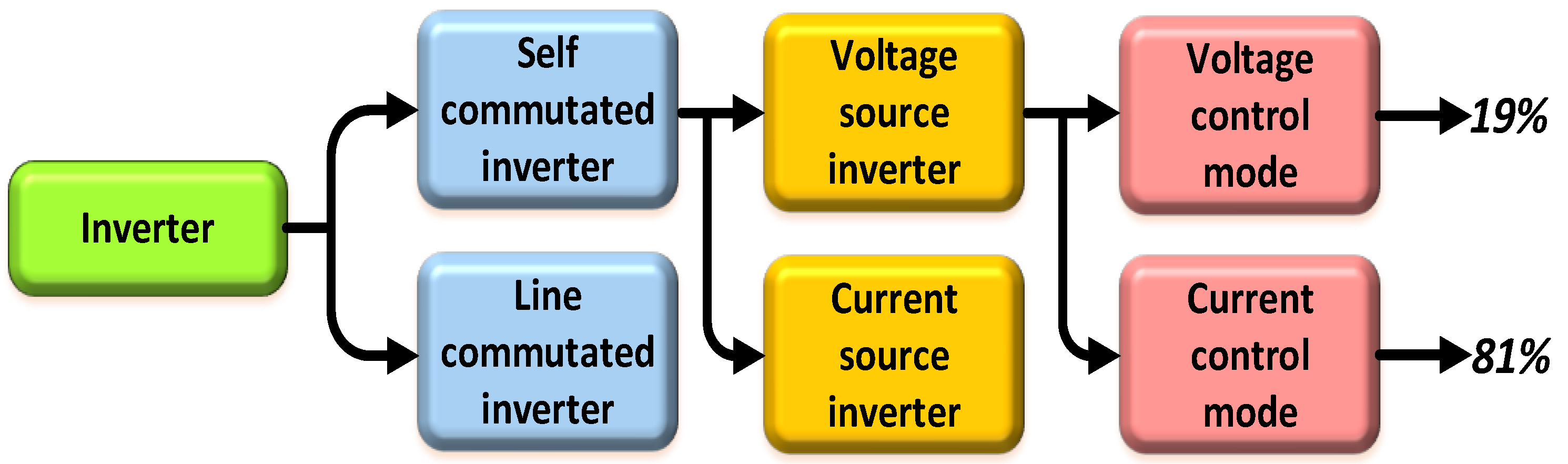
  • Current source inverter: Since the inverter’s input is connected to a DC source, the CSI approach guarantees that the polarities of an input current are preserved. Because of this, the pattern of power flow is decided by the polarities of the DC voltage that comes from the source. The current waveforms that were recorded on the output side of the CSI were variable in terms of their width but stable in terms of their amplitude. The most significant disadvantage of utilizing CSI is that an inductor of considerable size will be required for this application to solve the issue of current stability [72]. If an inductor is employed, the circuitry will be less effective, bigger, and more expensive [73].
  • Voltage source inverter: To provide a VSI with power, a DC power supply must be attached for it to function as an intake; the polarity of the input voltage is preserved. As a result, the orientation of the input power has no effect on the flow of power, which makes it unstoppable. The amplitude of an outputs AC voltage waveform is constant, while the width varies. Another significant problem of VSI is that it needs an enormous capacitor to be connected in parallel with the source of input [72]. When compared to CSIs, VSIs are recommended for grid-tied PV applications because of their low cost, high efficiency, lightweight nature, and relatively low power losses. This is because CSIs have a higher initial investment. In addition, VSIs may be used in VCM or CCM mode depending on the control mode. The voltage in the VCM is maintained at a constant level and adjusted only at the point of common connection (PCC). The line current, which is controlled by the PCC in CCM, is one of the controller’s primary control parameters. In comparison to CCM, VCM has a higher fault short circuit current. Additionally, applications such as off-grid or independent PV systems, where keeping the frequency, phase, and voltage at PCC are crucial, often employ VCM. The grid-tied PV VSIs may, however, be utilized with either CCM or VCM; nonetheless, CCM is the preferred and most often used approach [74]. Only 19% of VSIs are run in VCM for grid-tied applications, compared to about 81% of VSIs operating in CCM. This is because the current is an uncontrolled variable in the CCM, but it is a major control parameter in the VCM; this explains why the CCM is mostly used. The current control configuration used by CCM makes it easy to attain a high power factor and, as a consequence, is able to efficiently eliminate current transients and harmonic distortion in the event of any disruption to the grid [75].

2.2.4. Advantages and Disadvantages of MLIs

Table 3 shows the advantages and disadvantages of various common inverters that have been proposed around the world.

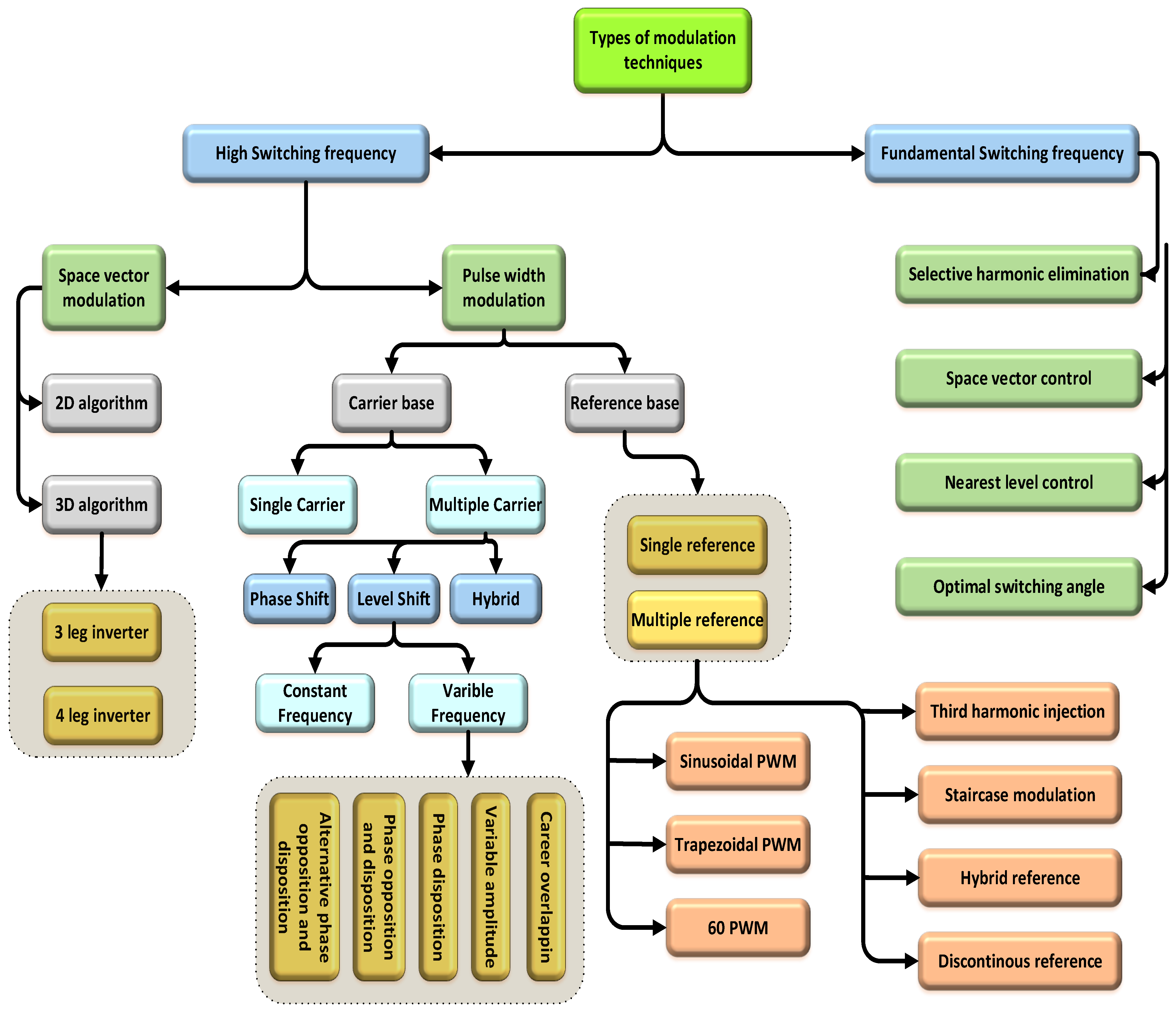
3. Modulation Techniques for Multi-Level Inverters

Switches employed in MLIs must have adequate control over their operation sequence and step length since these factors directly impact system performance [83]. Researchers developed a number of modulation methods as a result, which will be covered in more depth in this part. The primary function of MTs is current and voltage regulation and they also significantly contribute to reducing THD and switching losses. According to the taxonomy tree in Figure 10, the two primary categories for MTs based on switching frequency are FSF and HSF, which are further split into several varieties [84].

3.1. High Switching Frequency (HSF)

Multiple commutations occur during each cycle of the gating signals produced using this approach, and these cycles may or may not be similar to one another [85]. There are two varieties of high switching frequency MT, PWM, and space vector modulation (SVM); here is a summary of each one.

3.1.1. Pulse Width Modulation (PWM)

A common modulation method, pulse width modulation (PWM), generates gating signals by comparing a sinusoidal waveform to a carrier waveform. The switches’ gate is then supplied with these signals in order to drive them. Frequency and duty cycle are the two factors that determine how PWM behaves [86]. Additionally, uni-polar and bi-polar 02 methods, or gating signals, are employed; employing a uni-polar strategy produces 03 voltage levels. A comparison is made between two VT signals that have opposing phases. In bipolar, one is equated with another to produce three levels of voltage in an inverter with just two levels [87]. PWM systems have been the subject of a lot of recent studies and have been used in various grid-connected multilevel inverters (GCMLIs) for a variety of objectives, such as in three-level NPCs to reduce switching and conduction losses [88]. A modified PWM approach is provided for lowered NPC in order to increase the number of levels in an inverter to improve output waveforms and decrease the cost. In the FC topology, the removal of harmonic components is accomplished by the use of a PWM approach in the low and high modulation index regions [89]. For the purpose of raising the supply line quality index, a PWM scheme was applied to the CHB topology in [90]. This technology is also used in modular MLI to boost power factor, reduce voltage stress on switches, reduce harmonic content, and provide a prompt dynamic response [91]. Reference-based and carrier-based PWM are the two basic categories under which PWM approaches are categorized.
  • Carrier-Based PWM (MCB)
This strategy may be used to improve GCls. The three primary MC-PWM system types are phase shift carriers (PSC)-PWM, level shift (LS)-PWM, as well as hybrid-PWM. PSC-PWM uses n-1 carriers with similar voltage and phase but varied phase angles to create a sequence of horizontal bands. N-1 carriers, on the other hand, are positioned in neighboring vertical bands in LS-PWM [92]. Further subcategories of the LS-PWM method include those that use a fixed or variable frequency output, phase opposition and disposition (POD) [87,93], and carrier overlapping [94,95]. As an alternative to POD, there are three other techniques: amplitude modulation (AM), phase modulation (PD), and five distinct variants of constant-frequency MT. As a result of this, the hybrid-PWM eventually incorporates all the advantages of both PSC and LS-PWM techniques.
  • Reference-Based PWM
A comparison is made between the reference signal (V) and the modulation signal (V) all the time in the reverse blocking (RB)-PWM system. Only when V is higher will a pulse be produced, activating the relevant power switch. However, if it is lower than the threshold, no pulse will be produced, and the switch will stay in the off-position [96]. V may be unipolar or bipolar depending on the configuration of MLI [93]. There are seven main kinds of RB-PWM approaches, which are (a) sinusoidal PWM (SPWM), (b) trapezoidal PWM (c) 60° PWM (d) hybrid reference, (e), staircase modulation, (f) discontinuous reference, and (g) third harmonic injection.
A trapezoidal reference is created by applying various limits to the triangle waveform’s magnitude to increase the voltage’s RMS value. The switching pulses are produced via the approach used by the authors in 1991, which compares a large number of trapezoidal waveforms with a triangular carrier. Although this method is referred to as an SPWM [97] if V C is compared. When using the staircase method, the number of levels needed in the output waveforms determines how many steps to take to produce the pukes. Additionally, crucial to this strategy is the choice of an appropriate modulation frequency; if there are more than 15 pulses in a cycle, it is not advised to utilize this approach [98]. When using 60° PWM, pulses are flattened from 60 degrees to 120 degrees during the positive half-cycles, as well as 240 degrees to 300 degrees during the negative half-cycles [98]. It is possible to decrease switching losses by using this strategy to remove output waveforms that include triple harmonics 3-0. When using a hybrid approach, the first half-cycle only makes use of one reference signal while the second half-cycle makes use of both reference signals. When producing hybrid reference signals, two different reference signals are merged and then combined again. When the selected harmonics are put into VT, the third harmonics injection (THI) reference is subsequently formed [99]. To correct the voltage offset and reduce switching losses, discontinuous reference signals are used [100].

3.1.2. Space Vector Modulation (SVM)

SVM was initially presented in 1964 by [101] and makes use of a digital modulating technique in which the reference waveforms and the waveform of an output voltage can only be generated by vector control signals [102]. An SVM-based design is composed of six distinct sectors that are set apart from one another based on commutation patterns. The output voltages are regulated and controlled by the SVM using a control algorithm in accordance with the demands in any switching condition [103,104]. In this approach, a considerable amount of research has been completed, including the application of an upgraded SVM methodology to a five-level NPCMLI to lower switching losses [105]. The SVM method is applied in the n-level FC-M1.1 switch states for voltage regulation and capacitor balancing. To improve changing state selection in CHBMLI, the SVM approach is used in conjunction with a DC-link balancing [106]. A dual SVM technique using FCMLI and FCMLI has been suggested as a possible option to regulate the modular MLIs in Illinois. The voltage on the capacitor is supposed to be balanced using this manner.

3.2. Fundamental Switching Frequency (FSF)

FSF is divided into four basic categories and has one or more commutations in each cycle [85]; they are covered in greater depth below.

3.2.1. Selective Harmonic Elimination (SHE)

The year 1964 marked the beginning of the first implementation of the SHE methodology, which at the time was also known as the harmonic elimination method [107]. The low-order harmonic components are removed while staying within the permitted limits using the switching angles, which are produced when a Fourier series is generated for the voltage waveform they are analyzing. It is used to decrease switching losses [108], eliminate certain low order harmonics and torque pulsation, and may be functional either ONLINE [109] or INLINE with the inverter if you choose. A SHE technique is frequently used because it is effective in improving the waveforms of the output of high-rated power electronics inverters and rectifiers. However, because an inverter’s voltage increases, the number of required equations increases, and its usage in inverters that include high voltage levels are not recommended. In recent times, SHE strategies have been combined with a wide range of intelligent algorithms, such as particle swarm optimization (PSO), genetic algorithms, and the bee algorithm (BA) in an effort to enhance the waveforms produced by the system. The seven-level CHB is processed with a mix of BA and SHE to provide an improved harmonic profile [110]. The linearity of the switching angle and THD control in asymmetric CHBMLI are also accomplished using PSO [111]. In comparison to other MTs, the SHE method produces a waveform at the output that is of superior quality and permits fine-tuning of the harmonics.

3.2.2. Switching Angle Calculation (SAC)

Harmonics reduction and improved output waveform quality are the major benefits of the SAC approach. If the value of the angle number (AN) is not chosen well, the waveforms that come out of the inverter may not be very good; AN is the moment when the voltage level changes. So, it must be calculated with accuracy and with no mistakes if the outputs are to have the smooth waveforms that are needed [112]. The major switching angles of an n-level inverter may be calculated using the second quadrant (90–180°) rotation. An alternative would be to set the switching angles to the third and fourth quadrants (180–270° and 270–360°, respectively) [113]. More SAC categories are half-equivalent phase, equivalent phase, half-height, and feedforward method. A comparison of these four SAC methods is shown in Table 4 [112]. In RE, feedforward MTs are often suggested since they may be utilized for any voltage level even though they have a broad frequency range and produce output waveforms with extremely low THD.

3.2.3. Space Vector Control (SVC)

The nearest vector control, also identified as SVC, has as its primary goal of identifying the vector that is adjoining to the reference in order to minimize the spatial or distance error between them [114]. The SVC approach is very suited and preferred to use for high voltage level MIAs because the SHE method operates at a higher switching frequency and is consequently better at reducing low order harmonics. Vector density rises proportionately to voltage level as it rises; however, the probability of creating mistakes will decrease with increasing vector density. Consequently, THD is reduced, and the output waveforms exhibit undulations. The errors increase as the number of MLI voltage levels drops, leading to a linear rise in THD and ripples [115]. Three layers of the NPC-multilevel inverter obtain space vector control to moderate and equalize the DC bus voltage [116]. The induction motor’s cascaded MLI waveforms are improved using the SVC approach [117]. In addition to that, SVC also works well under low switching frequencies and does not produce the mean value of the wanted load voltage in every switch interval [118]. Compared to carried-based PWM methods, it has better performance if the number of levels is high enough to obtain a high switching factor density, which reduces the error produced with a single vector determination [12]. SVC is also known as one of the simple and easily utilized in standard DSP motor controllers [119]. The cascaded H-bridge multilevel Z-source inverter is controlled using SVC to achieve output voltage with a low THD level. The switching loss in devices can be reduced by using the SVC method in CHBMLIs [120]. Utilization of the nearest vector selection approach along with the SVC method improves the applicability of the SVC method in medium and high voltage MLIs [121]. It also enhances the harmonic distortion’s characteristics of waveforms [120,122].

3.2.4. Nearest Level Control (NLC)

NLC is a non-carrier method and is also called a round MT. Round modulation is a term used to describe the non-carrier NLC method. A non-linear comparator (NLC) is a technique for finding the nearest voltage level to a sinusoidal reference. The NVC uses the closest level instead of the vector, and it is much simpler to discover that nearest level than that of the vector which is to find a local level. Additionally, it can easily be extended to N-level under operating at 50–60 Hz [123]. The NLC technique produces better voltage waveforms and reduces output/load current ripple as a consequence [124]. Directly calculating the duty cycle and switching state for every inverter phase is possible using this approach. High-power inverters such as MLIs with several levels benefit greatly from this function. When compared to PWM-based methods, the NLC technique also minimizes the volume of switching events for high voltages [125] in order to reduce lower order harmonics and to obtain lesser switching losses [126]. However, the NLC scheme is not suitable for lower output voltage levels at a low modulation index due to its high harmonic distortion at this condition [123]. As the result, NLC is well-known as efficient and fast in terms of application procedures [127]. Additionally, the NLC method is a popular technique used in modular MLIs due to its flexibility and ease of implementation. The utilized NLC method in modular MLIs neither requires individual sorting of the submodule voltages nor the redundancy of the switching states [128]. Using this method, high-voltage modular MLIs achieve high-quality output performances. However, in medium-voltage applications, NLC faces several challenges such as high THD and large ripples due to the relatively low number of submodules of modular MLIs. Hybrid NLC with PWM control strategy is developed to improve the output voltage performance of MLIs [129].

4. Control Methods of Grid-Tied Multi-Level Inverters

Voltage is meant to remain constant in power systems, however, it is not. As a result, we must maintain control over it for it to stay consistent. Most gadgets, equipment, electrical machinery, consumer appliances, and other items, on the other hand, are intended to operate at a certain voltage. Wide voltage changes may result in operational faults, malfunctions, or a decrease in performance. It is ideal for users to obtain electricity at a somewhat steady voltage. In many nations, voltage fluctuation is limited to 6% of the reported voltage at the consumer’s end. As a result, it’s critical to use certain procedures and approaches to maintain a consistent voltage in the power system. The techniques for controlling voltage in a power system are listed below [130].

4.1. Control Techniques of GCMLI

GCMLIs need a control method in sync with the grid voltage to ensure that pure sinusoidal current is sent into the grid, maintains a power factor of 1, as well as reduces reactive power consumption. PV panels should be able to generate all their active power while their voltage across the load is still greater than the grid peak voltage [131]. It is important that the controller for MLI with multiple DC sources regulate the DC link voltage individually so that the PV panels may obtain the maximum amount of electricity [132]. The controller must similarly be capable to keep the system stable under a variety of weather situations, such as changing irradiance and temperature [131]. It should also offer selective compensation, such as harmonic or reactive current compensation, to reduce load current disruptions [133]. For safety and to keep switching losses to a minimum, a GCMLI with a hysteresis current controller must try to keep the switching frequency constant [134]. The grouping of the single-phase and three-phase GCMLI control methods are presented in the subsections below. The different theories of control applied to the control methods were discussed in the subsequent sections.

4.2. Control Techniques for Control Voltage Source GCMLI

Many control strategies have been proposed for grid-connected applications [135,136], all of which use the single source MLI. This review considered about five different ways to control NPC GCMLI which are the direct current control (DCC) [137]; sliding mode control (SMC) [138] voltage-oriented control (VOC) [139] and inner current and outer voltage closed-loop control [136,139]. The VOC control method is used in distributed generation (DG) systems [135]; it is extensively employed in the control of interfaced inverters and PQ compensators. In the improved VOC approach shown in Figure 11, the PV system simultaneously functions as a reactive power compensator, a shunt active power filter, and a load current balancer. As a result, the PV system is more efficient than typical PV systems and provides additional amenities to the utility grid. Space vector modulation (SVM) is used by the controller; the control method described above only works for three-level inverters. The DCC method, on the other hand, [138], may be used with inverters at the m-level. This method of control not only keeps the line current at a precise level, but also keeps the system’s behavior flexible and dynamic even if something goes wrong.
A space vector-based control system controller is shown in Figure 12. Translating and filtering grid currents are also included in the blocks for measuring three-phase orthogonal and non-orthogonal orthogonal coordinates (a-b-c). Several second-order generalized integrators and a sinc3 filter are used to filter the measured grid current (multi-SOGI). The DC link balancing algorithm selects the switching vector that minimizes the resistance change among capacitors based on the current controller’s findings. The non-linear control methods for a GCMLI include a sliding mode control (SMC) that offers a fast response and is consistent with the changing order of inverters [139].
SMC, on the other hand, has a chattering issue, which results in high switching frequency triggering pulses and variables that contribute to larger switching losses [136] and charge a fixed PWM-based SMC as shown in Figure 13 and Figure 14; it uses Gao’s reaching law to fix the chattering issue. The only thing needed to use this control method is an L-filter; an accurate tracking response, minimal THD, and ripple with grid-injected current and a smoother DC bus voltage are also needed when outside disturbances happen.
Figure 15 depicts a versatile and high effective power controller for an NPC inverter that could operate in both constant and transient settings [140]. Not only can the controller detect reactive power fluctuations at a faster rate, but it can also adjust power mechanisms at all switching frequencies. This controller’s distinctive characteristic is that it could be adapted to any of these converter topologies and can be utilized in distributed power generating systems.
Figure 16 shows the control approach for a PV system that is connected to the grid with an active power filter (APF) and FC multilevel inverter [142]. The APF’s predictive controller uses the instantaneous values of P and Q to compute the reference current. The P-Q theory is used to discover the two-phase P-Q components from the three-phase P-Q voltages and currents. It is also possible to establish the APF’s voltage level using the voltage mode control approach. Grid-connected solar systems using ANPC converters may encounter pulsed power, resulting in a DC-link unbalance issue. The consistency of average voltages across the DC links might be affected by the size of the FC signal used to calibrate the DC links.
Figure 17 and Figure 18 depict a schematic of two grid-connected control systems, with the performance of the traditional modulator [140] compared to the suggested modulator [143]. The controller in traditional approaches can only create and adjust the converter’s desired output voltage (Vo*), and the FC voltage is always controlled by Vdc/4. The suggested control method utilized an extra reference voltage (Vfc*) as an input of the modulator for the FC, giving the system more control flexibility. This new function also aligned DC-link capacitor voltages, which improved voltage. Because of the difference in power across PV arrays, the PV output is reduced when using a GCMLI system.
The controller developed by [136] solves the problem of mismatched power in PV arrays. A DC link controller block makes sure that the voltage of the whole DC link is balanced. A modulator block generates the switching pulses needed by the inverter to accommodate the intermittency of individual PV arrays. To generate pulses for three-phase 4 NPC, the modulator block makes use of a duty ratio-adjustable virtual vector-based PWM.
In addition to making a PV array voltage independent of its MPP, this control approach enhances the output voltage’s quality, which makes it possible to run the inverter without a transformer and increases its efficiency. The modular multi-level converter (MMC) which is described by [144] causes major problems when used with a PV grid system. The inverter’s overall efficiency and system stability are also impacted by the MMC’s circulating current. The study by [144] looks at the issues caused by MMC’s unregulated circulation current and proposed a novel PWM approach known as selective virtual loop mapping (SVLM).
The mapping procedures between the real sub-module (RSM) and virtual sub-module (VSM) are altered to steady the capacitor voltages in both arms of the bridge. The controller has the distinct benefit of being able to be implemented for large-scale generation.

4.3. Control Techniques of Multiple Voltage Sources Fed Symmetric GCMLI

Inverters with several DC link voltage sources for multi-level inversion, including PV have several concerns. As all H-bridges in such a CHB-based GCMLI exchange the same amount of grid current, a separate input power control loop is required. A controller for a CHB converter with n modules was proposed in [145]. The voltage and current are kept constant by outside current loops while a power factor of 1 is maintained in the inner loop. However, no mention is made of the system’s power imbalance or stability when there are variations in sunlight and warmth. Dual inverter architectures with three-phase, two-level inverters (and) may be managed by using two controllers, named sigma and delta. The DC link voltage should be adjusted to the same number. The inverter and open-end winding transformer deliver the same amount of power into the grid, thanks to the sigma controller’s creation of a grid reference current. This is performed with a current controller that works based on how the voltage feeds forward. For the MLI, a simplified state space machine generates gate pulses (SVM). In addition to temperature and light intensity variations, the controller can manage any operating circumstance. However, if an MLI contains upwards of two inverter bridges, the control technique must be expanded [146,147].
Controlling PV systems using a model of the system’s energy sampling is a common practice. The inverter bridge’s energy balance controller was implemented using a digital PI controller with closed-loop dynamics [103]. An inverter output current controller also monitors the energy balance of the controller’s reference current. Poor power quality, overmodulation, as well as an inconsistent ac output voltage, are all potential outcomes of active power mismatches in CHB inverter modules. The control scheme provided by [148] did not cover the concerns with leakage current. Individual converter modules might thus be directly linked to high-voltage large-scale PV systems’ PV arrays. A large grid-connected cascaded PV system featuring DC-DC converters and cascaded multilevel inverters use a decoupled total power controller to tackle all of these concerns. According to [148,149], the CF-DC-DC DAB’s converter is controlled by a single H-bridge module mostly on CHBMLI. It uses a PI and PR controller to change the duty ratio (D) and phase shift angle in order to switch between the PV voltage and the DC-link voltage. The PV double frequency component is blocked by setting the PI controller’s bandwidth high, and the PR controller’s gain is set to a high level to keep the low voltage side (LVS) voltage exactly in line with the reference voltage [150]. However, CHBMLI includes a separate control loop that controls the DC voltage of each inverter module independently and monitors the PI controller’s reference voltage. The decoupled loop is in charge of controlling the grid current’s d-q components and voltage [151].
Inverter-based GCMLIs with cascaded twin inverters are controlled using SMC, a dynamic control method (You may find the solution in [152]). The CTLI-based cascaded two-level inverter is used to show control strategies for a three-phase dual inverter [153]. To control grid current, SMC uses hysteresis modulation, while the conventional vector method is used for the outer DC-link voltage control loop. Two-level switching using forced switching at a constant frequency and variable frequency feedback current control have been used to generate gate pulses for primary to secondary inverters [133,152]. The fundamental approach for controlling the grid’s current was published in [154] for the five T-type inverters supplied by the DC source with much more than one string. Each DC-DC converter has a series connection of three PV strings. The distributed MPPT is often used to deliver the duty ratios of the linked DC-DC so that the standard grid current may be generated. PI controllers deal with the resulting error signal to provide the five-level inverters with the correct pulses for the anti-windup function. The controller performs well under a variety of conditions, including varying wind irradiance. It is necessary to have outer voltage control loops when working with an m-level cascaded T-type inverter that contains n modules in order to ensure that the voltages on the DC links are equalized. Only (n−1) total voltage controllers, each with a single voltage regulator, are required (this has been covered by the authors in [155]). Injecting sinusoidal current into the grid at constant energy efficiency also requires one internal current control loop. With a dual reference, the proposed cascaded MLI’s T-type inverter circuits create a switching pulse PWM technique that corrects the carrier phase shifting.
The authors in [156] presented a control approach for a quasi-Z source (qZS) based cascaded GCMLI. The management of a single qZS inverter module is depicted in Figure 19. Parts of this management include an MPPT control, separate voltage peak voltage management for establishing a shoot-through duty ratio, as well as grid-injected power management reference signals. Adjusting the duty ratio of an MPPT controller allows every nth PV panel to function at the MPP when this is activated (MPP). The peak voltage of each DC-link is maintained at the same level using a DC-link voltage control [157].
An FPGA and a floating-point digital signal processor (FPDSP) were used by [153] to control the modified cascaded GCMLI in order to regulate the electrical grid for the whole system. A single closed-loop controller that focused mostly on proportional and resonant controllers was used to implement PWM. This controller generates the reference signal of carrier phase-shifted SPWM(CPS-SPWM) and the phase-locked loop with enhancements (EPLL) [158] obtains the amplitude ( E m ), frequency ( ω ), and phase angle ( θ e ) of the grid voltage (e) used to generate the topology transformation command ( S s w ) to change the operation from H-bridge inverter (HBI) into cascaded inverter mode. Then, [159] obtains the amplitude (Em), frequency (ω), and phase angle (θe) of the grid voltage (e) used to generate the topology transformation command (SSW) to change the operation from HBI to cascaded inverter mode.
MMC steady-state controller models are presented by [160] for unbalanced conditions (SLG fault). The controller’s primary function is to regulate the pleasant and unpleasant sequence current components (DCC) [161] using dual current control. The techniques for controlling positive sequence currents as given by [153] are used to create the positive sequence reference voltages (Vd+*, Vq+*) provided to the PLL. The phase current on the converter side is then separated into positive and negative sequence voltages (Vd*, Vq*) and controlled individually in d-q coordinates. Under imbalanced situations, the anti-windup PI controller effectively suppresses the negative sequence current.
Single-phase and three-phase modular cascaded grid-linked MLIs, and a distributed MPPT approach were employed by [162] to maximize the amount of energy generated by each solar array. This technology allowed for the regulation of DC-link voltages on an individual basis [163]. It is possible to correct for mismatches in PV arrays by using a three-phase cascaded converter controller as illustrated in Figure 20. The DC link voltage for the following GCMLI H-bridge (in a-phase) is generated by an MPPT in each module. In order to generate an error signal, a comparison is performed between the module’s actual link voltage and the reference value. There is a total voltage controller that receives the sum of all error signals and generates a reference signal for managing grid current. Distributed MPPT allows the controller to cope with issues produced by partial shading as well.

4.4. Control Techniques of Asymmetrical Cascaded GCMLI

Inverters with asymmetrical cascaded H-bridges (ACHMI) based on systematic power theory were presented in [164] as a control system for continuous power theory (CPT) [153]. The CPT is constructed in a manner that instantaneous power and current may be broken down into their respective components. The existing controller, which is displayed in [153], utilizes frequency response analysis in a fixed reference frame to achieve a speedier dynamic reaction. In addition, as illustrated in [153], there are two separate voltage controllers presented here: controllers with load current feedforward, as well as one that has a single loop. The instantaneous load voltage (Vpcc) may be fine-tuned with the help of the single-loop voltage controller, which does not need the detection of any current. However, it can only operate within a rather narrow voltage range despite the fact that it offers excellent stability. At the same time, a multi-loop voltage regulation using load current feed-forward and inductor current feedback is used because it can handle a wider range of load requirements. By using many loops instead of a single-loop controller, it is possible to regulate voltage over a wider range while still maintaining stability. As a consequence of this, either approach for controlling voltage can be utilized provided that the stability margin and steady-state responsiveness criteria are satisfied. In this scenario, there is no requirement for the adjustment of the reference frame, and it is possible to apply it to asymmetric cascaded MLIs that have non-linear loads.
Using an FC to control asymmetric cascaded full-bridge inverters asymmetric cascaded full-bridge inverters provides a variety of difficulties, the most significant of which is maintaining voltage equilibrium across the FC. Hysteresis-based controllers offer one potential method for achieving this goal [134]. These components include an output voltage compensator and the redundant state selection (RSS) table, as well as base-level computations and a phase-locked loop (PLL). The reference current’s amplitudes angle may be used to determine the voltage compensator’s output and the required power factor.
A thorough capacitor voltage balancing approach was presented by [134] whereas [165] proposed a unique dedicated control circuit with an appropriate switching strategy for controlling the voltage of FCs. Closed loop hybrid switching may be used to regulate a trinary asymmetric 27-level PV inverter in a closed loop [166]. Grid-connected PV systems may use this two-loop method [153] as well, where an outer voltage control loop controls power output from a PV module, while an inner current control loop maintains the unity power factor in grid current; however, a timer with a left and right justification as per [166], should be used. For the purposes of computing the ceiling, slope, and floor values, the auxiliary H-bridge modules are used as a reference. As illustrated in Figure 21, a zero-error signal may be added to a closed-loop control system to achieve steady-state operation and the best results.
In order to correctly monitor grid voltage variations for an asymmetrical reducing switch MLI [131,153] described a closed-loop grid controller with outside voltage control, an inner reference voltage controller, as well as a grid voltage tracker. The DC link voltage ratio of an asymmetrical MLI is anticipated to remain constant and balanced under the careful eye of a total voltage controller. Using a decentralized MPPT controller in combination with PV panel reconfiguring may solve the PV incompatibility problem.

4.5. Control of Hybrid GCMLI

In a GCMLI architecture that is based on a packed U-cell (PUC), there is a direct relationship between grid current and capacitor voltage, both of which are control variables [136,137,138,139,140,141,142,143]. Because each change in one of the control variables has an impact on the others, the controller has been set up so that it will carefully regulate the PUC converter that is linked to the grid. The study by [153] illustrates the model predictive control (MPC) architecture in its general form [167]. The MPC is utilized to make predictions regarding the value of foreseeing the future value of a variable using the current value. After that, the value that should be used is arrived at by computing the cost function. For the PUC inverter, there is a minimal, yet optimum function offered. The PUC converter’s complicated dynamics have necessitated the development of a number of MPC techniques in the literature [168].
Control variables, as well as input/output delays and unstable systems, may all be handled using the MPC approach. According to the authors in [169], an MPC technique based on a finite control set (FCS) and optimizing techniques such as incremental conductance (IC) and MPPT are employed to build the reference vector. The PI controller that creates the grid reference current vector receives the error signal. To be as successful as possible in both steady-state and quick transient situations, the weighting factor must be selected with great deliberation. This method may also be utilized to balance the voltage across a capacitor at any value that is required [169]. A comparison of the most important controllers for GCMLI are highlighted in Table 5.

5. Innovative Control Approaches of Grid-Connected Multi-Level Inverter Systems

Recently, innovative control approaches have been developed for grid-connected MLIs utilized in industrial applications such as renewable energy resources and microgrids. A simulation and study of grid-linked multilevel converter topologies were described in [170]. By regulating the switching angle, the converter circuit acts as an inverter in this study. A MATLAB/SIMULINK model of multilevel converter topologies (topology 1 and topology 2) was described in this work. Topology 1 does not have a transformer; however, topology 2 does. For three-level converters, both topologies are simulated and examined to decrease overall THD. This report also included a comparison of topology 1 and topology 2 for various switching angles and battery voltages.
The study by [171] provides an innovative technique for managing a grid-linked microgrid of five smart Moroccan prosumers. The suggested energy management system utilizes three levels of the organization: load scheduling, hybrid renewable energy source (HRES), and HRES communication sharing. The first two tiers of energy management are handled locally in each smart home. For the third level, the article proved the possibility of interactions and communication between the five distinct residences that were networked as a smart neighborhood grid utilizing an optimal infrastructure architecture. Each of the residences had its own hybrid renewable energy system, which included a wind turbine, system hybridization, battery storage and PV. An energy management algorithm for a multi-level system was presented, and it allowed each household to control its surplus and deal with energy shortages. A microgrid of interconnected smart homes may help develop the “internet of sustainable green things” via the use of communication and information technology. Microgrid excess injection and also neighborhood storage during severe excesses, followed by load dynamics and also a microgrid injection of energy recovery at hybrid energy shortage, is a successful technique, according to MATLAB simulations. The suggested system controlled the energy generated by HRESs and lowered the energy required by the utility grid by using the proposed topology, which links households and assures interactions between the microgrid and the utility grid. Microgrid shortfalls were shown to be less frequent thanks to a multi-level management solution and a microgrid constructed with five residences built in accordance with the intended topology.
A paper with efficient model predictive current control (MPCC) algorithms for multi-level (ML) inverters connected to the grid was published by [172]. The suggested method uses a discrete-time model to predict how the grid-connected inverter (GCI) will work in the future. This is completed so that the control goals of quick dynamic and low ripples of the grid current, capacitor voltage balancing, and minimizing the number of switches can be met. These three control goals are put together into a single cost function that is used to calculate and analyze the inverter’s switching states. An inverter may operate in the most efficient switching mode when this is used. Additionally, the generation process takes a lot of processing time. Additionally, the paper’s innovations included using a long-horizon prediction strategy to make up for the delay in computing, and a three-level neutral point clamped (3L-NPC) inverter to reduce control complexity and give a grid current with few ripples. Lastly, the results of the simulation showed that the suggested compensation worked.
The use of an advanced grid-connected single-phase reduction converter to develop a predictive current control method was reported by [173]. The suggested reduced converter was a generic architecture for cascaded multilevel converters that reduces the number of components while still generating a large number of levels. An MPC strategy was used to regulate the grid current in conjunction with the proposed topology. Both the intended 15-level reduced converter and the projected 31-level cascaded multi-level converter were controlled using model predictive control. Finally, the results from MATLAB/Simulink simulations of both converters are presented to evaluate the hypothesized simplified multi-level converter as well as the suggested MPC.
A two-stage DC/AC multilevel inverter with a modified MPCC approach for use in PV systems was recommended by [174]. For multilevel inverters, a modified MPC control method is utilized to determine the most efficient switching vectors by adjusting the DC-link capacitor voltages. A single-phase power system with a DC-link operating at 400 volts, as well as 220 volts and the 50-hertz output voltage was presented in this paper’s architecture. The PSCAD/EMTDC program was used to simulate the proposed construction using the modified MPC approach. As a consequence of the recommended construction and control mechanism, THD is lessened. This, in turn, reduces power losses and improves the reliability of the circuit. Switch voltage stress may be reduced by decreasing the number of active switches inside the current route. This reduces the PV leakage current and improves the overall efficiency. The proposed structure outlines a unique control method that may offer a symmetrical five-level voltage with decreased THD by choosing suitable switches for PV applications; if the voltage is appropriately controlled, this is achievable. The results and consequences of the above-mentioned innovations are compared in Table 6:

6. Challenges and Future Work Recommendations

Grid-connected PV systems are gaining worldwide attention and their capacity is intensively being increased every day; this is due to the ever-increasing demand for electrical power and advancements in power electronics devices and related technologies. Thus, the only sustainable way to keep up with the growing demand is by exploiting renewable energy resources; this includes solar PVs as one of the most important sources of renewable energy. However, the growing penetration of grid-connected PV systems is not without challenges. The integration of PV sources to the grid is very likely to introduce problems to the stability and reliability of power. To prevent significant threats due to the aforementioned problems, several regulatory standards have been introduced to foster a safe operating procedure for grid-connected PV systems. These standards include IEEE 1547, IEEE 929, IEEE 519, NFPA 70, UL 1741, and IEEE 1547.8 [180]. The following areas are identified as being in need of further research based on the reviewed literature:
  • The inconsistent power generated by PV sources remains one of the biggest challenges in a grid-connected PV system. The intermittent and non-controllable nature of power generated by PV sources may produce voltage variations which will further cause voltage disparity between PV, the point of common coupling, and the grid. Therefore, appropriate solutions will be required to ensure a steady energy supply regardless of the variable nature of solar energy [181].
  • Non-coordinated regulation of multiple PV source outputs might cause stability issues to the power grid. Having effective coordination for the operation of multiple PV sources has emerged as a major obstacle to the scheduling of a power system. To this day, researchers have been active in proposing ideas and solutions to the problem, primarily aiming to increase power generation while minimizing output fluctuations, power purchase prices, and maintenance costs [182].
  • The inevitable degradation of PV panels is also a major concern in a PV power system. Under the most ideal case, the degradation of a PV panel is at the rate of about 0.8% per year. However, the actual rate could be much higher when other factors such as contaminants, dust, humidity, ultraviolet radiation, and the possibility of increasing degradation rate over time. PV panel degradation lowers the amount of electricity produced throughout their lifespan and raises the cost of the overall power generation [183,184].
  • The implementation of a transformer-less grid-connected PV system introduces common-mode problems. Despite producing higher efficiency at reduced overall power generation cost due to the lack of galvanic isolation between PV systems and grids, the parasitic capacitance which lies between the PV modules and the ground, as well as the grid, creates the common-mode circuit. As a result, the common-mode current in the PV system has a negative effect on the overall system’s safety [185,186].
  • The implementation of MLI with high numbers of output levels is also a challenge in a grid-connected PV system. Waveforms with a high number of output levels have a very close resemblance to a pure sinusoid and are advantageous in a lot of ways, including lower harmonics and minimum filtering requirements; however, the complexity of the modulation and control system will also increase with an increasing number of output levels. This is because of the difficulty in controlling the AC side voltage using standard control techniques due to the limited range at which the modulation index can be adjusted [187].
  • As discussed in this paper, MLIs have been widely employed for integrating RESs into the power grid due to their numerous advantages. However, hybrid topologies and innovative control approaches have recently been introduced to meet the high grid code and resolve the challenges of the classical topologies in a cost-friendly manner [188]. Since most of the developed new topologies and control approaches have not been utilized for integrating RESs into the power grid, there is a need to evaluate their performance in grid-integrated applications.
  • Modular MLIs are one the most suitable MLIs topologies for large-scale integration of RESs. Modular MLIs could significantly improve the reliability and flexibility of the power grid due to their salient features. However, there are still several technical challenges in the modeling, control, and protection of the modular MLIs used in RES applications [189,190].
  • Utilization of RESs using suitable MLIs enables power grids to move gradually towards smart grids. This will introduce several challenges in the control and protection of the power grid. However, RES-enhanced smart grids present some opportunities for MLI topology development and control that need to be investigated and studied.

7. Conclusions

This article provided a thorough examination of grid-connected multi-node inverters. The principles and in-depth knowledge of multi-level inverters, as well as their problems, were examined. Different topologies of MLIs were discussed and classified from different viewpoints such as number of stages (i.e., single-stage and multiple-stage types) and inclusion of transformers (i.e., transformer-based and transformer-less topologies). Moreover, MLIs were further classified based on commutation, switching methods, and their topologies. The main topologies include the half-bridge and full-bridge clamped inverters, cascaded inverters, and flying inverters and the characteristics of each MLI topology was studied in detail.
In addition, modulation approaches of MLIs were described in the next part of the paper. The primary function of modulation approaches is current and voltage regulation, and they also significantly contribute to reducing THD and switching losses. The MTs were classified into two common types of modulation approaches based on switching frequency, i.e., fundamental switching frequency (FSF) and high switching frequency (HSF). These approaches were further split into several varieties and discussed in detail. Within these approaches, the primary techniques were explored, which include the space vector modulation (SVM) and pulse width modulation (PWM) techniques from HSF category and selective harmonic elimination, space vector control, nearest level control, and optimal switching angle methods from FSF category.
Furthermore, the control approaches for the grid-connected MLIs (GCMLI) were discussed and presented. In this section of the paper, the control strategies for voltage sources GCMLI, voltage source fed symmetric GCMLI, asymmetrical cascaded GCMLI, and hybrid GCMLI were discussed thoroughly.
Finally, some of the newly suggested GCMLIs were addressed, including some of the author’s inverter innovations, as well as research findings and challenges that might be useful for future studies.

Author Contributions

Conceptualization, M.S. and A.R.; methodology, I.A. and A.R.; writing—original draft preparation, M.S., I.A. and K.Y.; investigation, K.Y., M.S. and A.R.; resources, M.N.H. and I.A.; writing—review and editing, M.S., T.-Z.A. and M.N.H.; visualization, M.S., T.-Z.A. and A.R.; supervision, M.S. and A.R; funding acquisition, A.R. and M.S. All authors have read and agreed to the published version of the manuscript.

Funding

This work was supported in part by Universiti Sains Malaysia, under short-term grant No. 304/PELECT/6315330.

Institutional Review Board Statement

Not applicable.

Informed Consent Statement

Not applicable.

Data Availability Statement

Not applicable.

Acknowledgments

The authors would like to pay gratitude to the Research Creativity and Management Office (RCMO) of the Universiti Sains Malaysia for supporting with funding under the Short-term grant No. 304/PELECT/6315330, and library facilities. Lastly thanks to those colleagues who have either directly or indirectly contributed to the completion of this work.

Conflicts of Interest

The authors declare no conflict of interest.

Abbreviations

MLIMultilevel inverter
RESRenewable energy systems
ACAlternative current
DCDirect current
PVPhotovoltaic
CHBMLICascaded H-bridge multilevel inverter
EMIElectromagnetic interference
MTsModular techniques
MPPTMaximum power point tracking
PWMPulse width modulation
THDTotal harmonic distortion
NPCNeutral point clamped
CHBCascaded H-bridge
MPPMaximum power point
LFTLow frequency transformer
HFTHigh frequency transformer
FFFFast Fourier frame
ZVSZero voltage switching
ZCSZero current switching
ZVTZero voltage transition
FCMLIFlying capacitor multilevel inverter
DCMLIDiode clamped multilevel inverter
NPCNeutral point clamped
SCISelf-communication inverters
LCILoad commutated inverter
VSIVoltage source inverter
CSICurrent source inverter
CCMCurrent conduction mode
VCMVoltage conduction mode
CMConduction mode
PCCPoint of common connection
ANPCActive neutral point clamped
SVMSpace vector modulation
GCMLIsGrid connected multilevel inverters
PSCPhase shift carriers
LSLevel shift
PODPhase opposition and disposition
RBReverse blocking
SPWMSinusoidal pulse with modulation
THIThird harmonics injection
FSFFundamental switching frequency
SHESelective harmonic elimination
PSOParticle swarm optimization
BABee algorithm
SACSwitching angle calculation
ANAngel number
SVCSpace vector control
NLCNearest level control
VOCVoltage oriented control
DCCDuty cycle correction
SMCSliding mode control
SMCCSliding mode current control
APFActive power filter
MMCModular multilevel controller
DDuty ratio
LVSLow voltage side
qZSQuasi-Z source
FPDSPFloating-point digital signal processor
CPS-SPWMCarrier phase-shifted
HBIH-bridge inverter
ACHMIAsymmetrical cascaded H-bridge
CPTContinuous power theory
RSSRedundant state selection
PLLPhase-locked loop
PUCPack U-cell
MPCModel predictive control
ICIncremental conductance
FCSFinite control set
HRESHybrid renewable energy source
MPCCModel predictive current control
GCIGrid connected inverter
3L-NPCThree-level neutral point clamped

References

  1. Mahalakshmi, R.; Thampatty, K.S. Grid connected multilevel inverter for renewable energy applications. Procedia Technol. 2015, 21, 636–642. [Google Scholar] [CrossRef]
  2. Li, W.; Ruan, X.; Bao, C.; Pan, D.; Wang, X. Grid synchronization systems of three-phase grid-connected power converters: A complex-vector-filter perspective. IEEE Trans. Ind. Electron. 2013, 61, 1855–1870. [Google Scholar] [CrossRef]
  3. Bughneda, A.; Salem, M.; Richelli, A.; Ishak, D.; Alatai, S. Review of multilevel inverters for PV energy system applications. Energies 2021, 14, 1585. [Google Scholar] [CrossRef]
  4. Daher, S.; Schmid, J.; Antunes, F.L. Multilevel inverter topologies for stand-alone PV systems. IEEE Trans. Ind. Electron. 2008, 55, 2703–2712. [Google Scholar] [CrossRef]
  5. Vahedi, H.; Sharifzadeh, M.; Al-Haddad, K. Modified seven-level pack U-cell inverter for photovoltaic applications. IEEE J. Emerg. Sel. Top. Power Electron. 2018, 6, 1508–1516. [Google Scholar] [CrossRef]
  6. Abdoli, H.; Khorsandi, A.; Eskandari, B.; Moghani, J.S. A new reduced switch multilevel inverter for pv applications. In Proceedings of the 2020 11th Power Electronics, Drive Systems, and Technologies Conference (PEDSTC), Tehran, Iran, 4–6 February 2020; IEEE: Piscataway, NJ, USA, 2020. [Google Scholar]
  7. Agrawal, R.; Jain, S. Comparison of reduced part count multilevel inverters (RPC-MLIs) for integration to the grid. Int. J. Electr. Power Energy Syst. 2017, 84, 214–224. [Google Scholar] [CrossRef]
  8. Xiao, B.; Tolbert, L.M. Efficiency improved and current balanced three-phase modular cascaded H-bridge multilevel PV inverter for grid-connected applications. In Proceedings of the 2014 IEEE Energy Conversion Congress and Exposition (ECCE), Pittsburgh, PA, USA, 14–18 September 2014; IEEE: Piscataway, NJ, USA, 2014. [Google Scholar]
  9. Bana, P.R.; Panda, K.P.; Naayagi, R.; Siano, P.; Panda, G. Recently developed reduced switch multilevel inverter for renewable energy integration and drives application: Topologies, comprehensive analysis and comparative evaluation. IEEE Access 2019, 7, 54888–54909. [Google Scholar] [CrossRef]
  10. Balal, A.; Dinkhah, S.; Shahabi, F.; Herrera, M.; Chuang, Y.L. A Review on Multilevel Inverter Topologies. Emerg. Sci. J. 2022, 6, 185–200. [Google Scholar] [CrossRef]
  11. Pharne, I.; Bhosale, Y. A review on multilevel inverter topology. In Proceedings of the 2013 International Conference on Power, Energy and Control (ICPEC), Dindigul, India, 6–8 February 2013; IEEE: Piscataway, NJ, USA, 2013. [Google Scholar]
  12. Rodríguez, J.; Bernet, S.; Wu, B.; Pontt, J.O.; Kouro, S. Multilevel voltage-source-converter topologies for industrial medium-voltage drives. IEEE Trans. Ind. Electron. 2007, 54, 2930–2945. [Google Scholar] [CrossRef]
  13. Rodriguez, J.; Franquelo, L.G.; Kouro, S.; Leon, J.I.; Portillo, R.C.; Prats, M.A.M.; Perez, M.A. Multilevel converters: An enabling technology for high-power applications. Proc. IEEE 2009, 97, 1786–1817. [Google Scholar] [CrossRef] [Green Version]
  14. Kouro, S.; Malinowski, M.; Gopakumar, K.; Pou, J.; Franquelo, L.G.; Wu, B.; Rodriguez, J.; Pérez, M.A.; Leon, J.I. Recent advances and industrial applications of multilevel converters. IEEE Trans. Ind. Electron. 2010, 57, 2553–2580. [Google Scholar] [CrossRef]
  15. Hasan, N.S.; Rosmin, N.; Osman, D.A.A.; Musta’amal, A.H. Reviews on multilevel converter and modulation techniques. Renew. Sustain. Energy Rev. 2017, 80, 163–174. [Google Scholar] [CrossRef]
  16. Shehu, G.S.; Kunya, A.B.; Shanono, I.H.; Yalçınöz, T. A review of multilevel inverter topology and control techniques. In Proceedings of the 2017 Nineteenth International Middle East Power Systems Conference (MEPCON), Cairo, Egypt, 19–21 December 2017. [Google Scholar]
  17. Peng, F.; McKeever, J.; Adams, D. Cascade multilevel inverters for utility applications. In Proceedings of the IECON’97 23rd International Conference on Industrial Electronics, Control, and Instrumentation (Cat. No. 97CH36066), New Orleans, LA, USA, 14 November 1997; IEEE: Piscataway, NJ, USA, 1997. [Google Scholar]
  18. Escalante, M.F.; Vannier, J.-C.; Arzandé, A. Flying capacitor multilevel inverters and DTC motor drive applications. IEEE Trans. Ind. Electron. 2002, 49, 809–815. [Google Scholar] [CrossRef]
  19. Gangavarapu, S.; Verma, M.; Rathore, A.K. A novel transformerless single-stage grid-connected solar inverter. IEEE J. Emerg. Sel. Top. Power Electron. 2020. [Google Scholar] [CrossRef]
  20. Attanasio, R.; Cacciato, M.; Gennaro, F.; Scarcella, G. Review on single-phase PV inverters for grid-connected applications. In Proceedings of the 4th IASME/WSEAS, International Conference on Energy, Environment, Ecosystems and Sustainable Development (EEESD’08), Algarve, Portugal, 11–13 June 2008. [Google Scholar]
  21. Caceres, R.O.; Barbi, I. A boost DC-AC converter: Analysis, design, and experimentation. IEEE Trans. Power Electron. 1999, 14, 134–141. [Google Scholar] [CrossRef]
  22. Vazquez, N.; Almazan, J.; Alvarez, J.; Aguilar, C.; Arau, J. Analysis and experimental study of the buck, boost and buck-boost inverters. In Proceedings of the 30th Annual IEEE Power Electronics Specialists Conference. Record.(Cat. No. 99CH36321), Charleston, SC, USA, 1 July 1999; IEEE: Piscataway, NJ, USA, 1999. [Google Scholar]
  23. Kasa, N.; Iida, T.; Iwamoto, H. An inverter using buck-boost type chopper circuits for popular small-scale photovoltaic power system. In Proceedings of the IECON’99 Conference Proceedings 25th Annual Conference of the IEEE Industrial Electronics Society (Cat. No. 99CH37029), San Jose, CA, USA, 29 November–3 December 1999; IEEE: Piscataway, NJ, USA, 1999. [Google Scholar]
  24. Xue, Y.; Chang, L.; Kjaer, S.B.; Bordonau, J.; Shimizu, T. Topologies of single-phase inverters for small distributed power generators: An overview. IEEE Trans. Power Electron. 2004, 19, 1305–1314. [Google Scholar] [CrossRef]
  25. Kusakawa, M.; Nagayoshi, H.; Kamisako, K.; Kurokawa, K. Further improvement of a transformerless, voltage-boosting inverter for ac modules. Sol. Energy Mater. Sol. Cells 2001, 67, 379–387. [Google Scholar] [CrossRef]
  26. Chaudhary, P.; Rizwan, M. Voltage regulation mitigation techniques in distribution system with high PV penetration: A review. Renew. Sustain. Energy Rev. 2018, 82, 3279–3287. [Google Scholar] [CrossRef]
  27. Wang, C.-M. A novel single-stage full-bridge buck-boost inverter. In Proceedings of the Eighteenth Annual IEEE Applied Power Electronics Conference and Exposition, 2003, APEC’03, Miami Beach, FL, USA, 9–13 February 2003; IEEE: Piscataway, NJ, USA, 2003. [Google Scholar]
  28. Ahmed, N.A.; Lee, H.W.; Nakaoka, M. Dual-mode time-sharing sinewave-modulation soft switching boost full-bridge one-stage power conditioner without electrolytic capacitor DC link. IEEE Trans. Ind. Appl. 2007, 43, 805–813. [Google Scholar] [CrossRef]
  29. Madouh, J.; Ahmed, N.A.; Al-Kandari, A.M. Advanced power conditioner using sinewave modulated buck–boost converter cascaded polarity changing inverter. Int. J. Electr. Power Energy Syst. 2012, 43, 280–289. [Google Scholar] [CrossRef]
  30. Jain, S.; Agarwal, V. A single-stage grid connected inverter topology for solar PV systems with maximum power point tracking. IEEE Trans. Power Electron. 2007, 22, 1928–1940. [Google Scholar] [CrossRef]
  31. Myrzik, J.M. Novel inverter topologies for single-phase stand-alone or grid-connected photovoltaic systems. In Proceedings of the 4th IEEE International Conference on Power Electronics and Drive Systems, IEEE PEDS 2001-Indonesia, Proceedings (Cat. No. 01TH8594), Denpasar, Indonesia, 25 October 2001; IEEE: Piscataway, NJ, USA, 2001. [Google Scholar]
  32. Meinhardt, M.; Cramer, G. Past, present and future of grid connected photovoltaic-and hybrid-power-systems. In Proceedings of the 2000 Power Engineering Society Summer Meeting (Cat. No. 00CH37134), Seattle, WA, USA, 16–20 July 2000; IEEE: Piscataway, NJ, USA, 2000. [Google Scholar]
  33. Ozkan, Z.; Hava, A.M. Classification of grid connected transformerless PV inverters with a focus on the leakage current characteristics and extension of topology families. J. Power Electron. 2015, 15, 256–267. [Google Scholar] [CrossRef]
  34. Kjaer, S.B.; Pedersen, J.K.; Blaabjerg, F. Power inverter topologies for photovoltaic modules-a review. In Proceedings of the Conference Record of the 2002 IEEE Industry Applications Conference. 37th IAS Annual Meeting (Cat. No. 02CH37344), Pittsburgh, PA, USA, 13–18 October 2002; IEEE: Piscataway, NJ, USA, 2002. [Google Scholar]
  35. Kjaer, S.B.; Blaabjerg, F. Design optimization of a single phase inverter for photovoltaic applications. In Proceedings of the IEEE 34th Annual Conference on Power Electronics Specialist, 2003. PESC’03, Acapulco, Mexico, 15–19 June 2003; IEEE: Piscataway, NJ, USA, 2003. [Google Scholar]
  36. Gu, Y.; Li, W.; Zhao, Y.; Yang, B.; Li, C.; He, X. Transformerless inverter with virtual DC bus concept for cost-effective grid-connected PV power systems. IEEE Trans. Power Electron. 2012, 28, 793–805. [Google Scholar] [CrossRef]
  37. Kala, P.; Arora, S. A comprehensive study of classical and hybrid multilevel inverter topologies for renewable energy applications. Renew. Sustain. Energy Rev. 2017, 76, 905–931. [Google Scholar] [CrossRef]
  38. Gerardo, V.-G.; Raymundo, M.-R.P.; Miguel, S.-Z.J. High efficiency single-phase transformer-less inverter for photovoltaic applications. Ing. Investig. Technol. 2015, 16, 173–184. [Google Scholar] [CrossRef]
  39. Junior, L.G.; De Brito, M.A.; Sampaio, L.P.; Canesin, C.A. Single stage converters for low power stand-alone and grid-connected PV systems. In Proceedings of the 2011 IEEE International Symposium on Industrial Electronics, Gdansk, Poland, 27–30 June 2011; IEEE: Piscataway, NJ, USA, 2011. [Google Scholar]
  40. Jana, J.; Saha, H.; Bhattacharya, K.D. A review of inverter topologies for single-phase grid-connected photovoltaic systems. Renew. Sustain. Energy Rev. 2017, 72, 1256–1270. [Google Scholar] [CrossRef]
  41. Sahoo, S.K.; Sukchai, S.; Yanine, F.F. Review and comparative study of single-stage inverters for a PV system. Renew. Sustain. Energy Rev. 2018, 91, 962–986. [Google Scholar]
  42. Radwan, H.; Sayed, M.A.; Takeshita, T.; Elbaset, A.A.; Shabib, G. A novel single-stage high-frequency boost inverter for PV grid-tie applications. In Proceedings of the 2018 IEEE Applied Power Electronics Conference and Exposition (APEC), San Antonio, TX, USA, 4–8 March 2018; IEEE: Piscataway, NJ, USA, 2018. [Google Scholar]
  43. Zhu, Y.; Yao, J.; Wu, D. Comparative study of two stages and single stage topologies for grid-tie photovoltaic generation by PSCAD/EMTDC. In Proceedings of the 2011 International Conference on Advanced Power System Automation and Protection, Beijing, China, 16–20 October 2011; IEEE: Piscataway, NJ, USA, 2011. [Google Scholar]
  44. Shayestegan, M. Overview of grid-connected two-stage transformer-less inverter design. J. Mod. Power Syst. Clean Energy 2018, 6, 642–655. [Google Scholar] [CrossRef]
  45. Alsolami, M. A multi-input, multi-stage step-up DC-DC converter for PV applications. Alex. Eng. J. 2021, 60, 2315–2324. [Google Scholar] [CrossRef]
  46. Ramasamy, S.; Perumal, M. CNN-based deep learning technique for improved H7 TLI with grid-connected photovoltaic systems. Int. J. Energy Res. 2021, 45, 19851–19868. [Google Scholar] [CrossRef]
  47. Calais, M.; Myrzik, J.; Spooner, T.; Agelidis, V.G. Inverters for single-phase grid connected photovoltaic systems-an overview. In Proceedings of the 2002 IEEE 33rd Annual IEEE Power Electronics Specialists Conference. Proceedings (Cat. No. 02CH37289), Cairns, Australia, 23–27 June 2002; IEEE: Piscataway, NJ, USA, 2002. [Google Scholar]
  48. Shinohara, H.; Kimoto, K.; Itami, T.; Ambou, T.; Okado, C.; Nakajima, K.; Hojo, S.; Owada, K.; Kuniyoshi, M.; Sato, Y. Development of a residential use, utility interactive PV inverter with isolation transformer-less circuit-development aspects. In Proceedings of the 1994 IEEE 1st World Conference on Photovoltaic Energy Conversion-WCPEC (A Joint Conference of PVSC, PVSEC and PSEC), Waikoloa, HI, USA, 5–9 December 1994; IEEE: Piscataway, NJ, USA, 1994. [Google Scholar]
  49. Lai, J.-S.; Peng, F.Z. Multilevel converters-a new breed of power converters. IEEE Trans. Ind. Appl. 1996, 32, 509–517. [Google Scholar]
  50. Bhagwat, P.M.; Stefanovic, V. Generalized structure of a multilevel PWM inverter. IEEE Trans. Ind. Appl. 1983, IA-19, 1057–1069. [Google Scholar] [CrossRef]
  51. Patrao, I.; Figueres, E.; González-Espín, F.; Garcerá, G. Transformerless topologies for grid-connected single-phase photovoltaic inverters. Renew. Sustain. Energy Rev. 2011, 15, 3423–3431. [Google Scholar] [CrossRef]
  52. Bose, B.K.; Szczesny, P.M.; Steigerwald, R.L. Microcomputer control of a residential photovoltaic power conditioning system. IEEE Trans. Ind. Appl. 1985, IA-21, 1182–1191. [Google Scholar] [CrossRef]
  53. Calais, M.; Agelidis, V.G. Multilevel converters for single-phase grid connected photovoltaic systems-an overview. In Proceedings of the IEEE International Symposium on Industrial Electronics, ISIE’98 (Cat. No. 98TH8357), Pretoria, South Africa, 7–10 July 1998; IEEE: Piscataway, NJ, USA, 1998. [Google Scholar]
  54. Marchesoni, M.; Mazzucchelli, M.; Tenconi, S. A nonconventional power converter for plasma stabilization. IEEE Trans. Power Electron. 1990, 5, 212–219. [Google Scholar] [CrossRef]
  55. Ali Khan, M.Y.; Liu, H.; Yang, Z.; Yuan, X. A comprehensive review on grid connected photovoltaic inverters, their modulation techniques, and control strategies. Energies 2020, 13, 4185. [Google Scholar] [CrossRef]
  56. Peng, F.Z.; Lai, J.-S.; McKeever, J.W.; VanCoevering, J. A multilevel voltage-source inverter with separate DC sources for static var generation. IEEE Trans. Ind. Appl. 1996, 32, 1130–1138. [Google Scholar] [CrossRef]
  57. Joos, G.; Huang, X.; Ooi, B.-T. Direct-coupled multilevel cascaded series VAR compensators. IEEE Trans. Ind. Appl. 1998, 34, 1156–1163. [Google Scholar] [CrossRef]
  58. Mahdavi, J.; Tabandeh, M.; Shahriari, A. Comparison of conducted RFI emission from different unity power factor AC/DC converters. In Proceedings of the PESC Record, 27th Annual IEEE Power Electronics Specialists Conference, Baveno, Italy, 23–27 June 1996; IEEE: Piscataway, NJ, USA, 1996. [Google Scholar]
  59. Mahdavi, J.; Roudet, J.; Scheich, R.; Rognon, J. Conducted RFI emission from an AC-DC converter with sinusoidal line current. In Proceedings of the Conference Record of the 1993 IEEE Industry Applications Conference Twenty-Eighth IAS Annual Meeting, Toronto, ON, Canada, 2–8 October 1993; IEEE: Piscataway, NJ, USA, 1993. [Google Scholar]
  60. Mohammed, S.A.Q.; Jung, J.-W. A State-of-the-Art Review on Soft-Switching Techniques for DC–DC, DC–AC, AC–DC, and AC–AC Power Converters. IEEE Trans. Ind. Inform. 2021, 17, 6569–6582. [Google Scholar] [CrossRef]
  61. Babaei, E.; Tarzamni, H.; Tahami, F.; Jahan, H.K.; Sharifian, M.B.B. Multi-input high step-up inverter with soft-switching capability, applicable in photovoltaic systems. IET Power Electron. 2020, 13, 133–143. [Google Scholar] [CrossRef]
  62. Huang, Y.-F.; Konishi, Y.; Ho, W.-J. Series resonant type soft-switching grid-connected single-phase inverter employing discontinuous-resonant control applied to photovoltaic AC module. In Proceedings of the 2011 Twenty-Sixth Annual IEEE Applied Power Electronics Conference and Exposition (APEC), Fort Worth, TX, USA, 6–11 March 2011; IEEE: Piscataway, NJ, USA, 2011. [Google Scholar]
  63. Tan, G.; Tang, Y.; Gao, B.; Fu, X.; Ji, Y. Soft-switching AC module inverter with flyback transformer for photovoltaic power system. Przegląd Elektrotechniczny 2012, 88, 180–184. [Google Scholar]
  64. Amorndechaphon, D.; Premrudeepreechacharn, S.; Higuchi, K. An improved soft-switching single-phase inverter for small grid-connected PV-system. In Proceedings of the 2008 34th Annual Conference of IEEE Industrial Electronics, Orlando, FL, USA, 10–13 November 2008; IEEE: Piscataway, NJ, USA, 2008. [Google Scholar]
  65. Chen, M.; Lee, X.; Tsutomu, Y. A novel soft-switching grid-connected PV inverter and its implementation. In Proceedings of the 2011 IEEE Ninth International Conference on Power Electronics and Drive Systems, Singapore, 5–8 December 2011; IEEE: Piscataway, NJ, USA, 2011. [Google Scholar]
  66. Meynard, T.A.; Foch, H. Multi-level conversion: High voltage choppers and voltage-source inverters. In Proceedings of the PESC’92 Record, 23rd Annual IEEE Power Electronics Specialists Conference, Toledo, Spain, 29 June–3 July 1992; IEEE: Piscataway, NJ, USA, 1992. [Google Scholar]
  67. Chen, A.; He, X. Research on hybrid-clamped multilevel-inverter topologies. IEEE Trans. Ind. Electron. 2006, 53, 1898–1907. [Google Scholar] [CrossRef]
  68. Nabae, A.; Takahashi, I.; Akagi, H. A new neutral-point-clamped PWM inverter. IEEE Trans. Ind. Appl. 1981, IA-17, 518–523. [Google Scholar] [CrossRef]
  69. Jayakumar, V.; Chokkalingam, B.; Munda, J.L. A comprehensive review on space vector modulation techniques for neutral point clamped multi-level inverters. IEEE Access 2021, 9, 112104–112144. [Google Scholar] [CrossRef]
  70. Alatai, S.; Salem, M.; Ishak, D.; Das, H.S.; Alhuyi Nazari, M.; Bughneda, A.; Kamarol, M. A Review on State-of-the-Art Power Converters: Bidirectional, Resonant, Multilevel Converters and Their Derivatives. Appl. Sci. 2021, 11, 10172. [Google Scholar] [CrossRef]
  71. Rodriguez, J.; Bernet, S.; Steimer, P.K.; Lizama, I.E. A survey on neutral-point-clamped inverters. IEEE Trans. Ind. Electron. 2009, 57, 2219–2230. [Google Scholar] [CrossRef]
  72. Mohamed Hariri, M.H.; Mat Desa, M.K.; Masri, S.; Mohd Zainuri, M.A.A. grid-connected PV generation system—Components and challenges: A review. Energies 2020, 13, 4279. [Google Scholar] [CrossRef]
  73. Ishikawa, T. Grid-Connected Photovoltaic Power Systems: Survey of Inverter and Related Protection Equipments; IEA International Energy Agency: Paris, France, 2002; pp. 1–17. [Google Scholar]
  74. Azmi, S.; Ahmed, K.; Finney, S.; Williams, B. Comparative analysis between voltage and current source inverters in grid-connected application. In Proceedings of the IET Conference on Renewable Power Generation (RPG 2011), Edinburgh, UK, 6–8 September 2011. [Google Scholar]
  75. Zeb, K.; Uddin, W.; Khan, M.A.; Ali, Z.; Ali, M.U.; Christofides, N.; Kim, H. A comprehensive review on inverter topologies and control strategies for grid connected photovoltaic system. Renew. Sustain. Energy Rev. 2018, 94, 1120–1141. [Google Scholar] [CrossRef]
  76. Al-Shetwi, A.Q.; Sujod, M.Z.; Blaabjerg, F.; Yang, Y. Fault ride-through control of grid-connected photovoltaic power plants: A review. Sol. Energy 2019, 180, 340–350. [Google Scholar] [CrossRef]
  77. Hojabri, M.; Soheilirad, M. Harmonic distortion in an off-grid renewable energy system with different loads. In Proceedings of the International MultiConference of Engineers and Computer Scientists, Hong Kong, China, 12–14 March 2014. [Google Scholar]
  78. Hinga, P.K.; Ohnishi, T.; Suzuki, T. A new PWM inverter for photovoltaic power generation system. In Proceedings of the 1994 Power Electronics Specialist Conference-PESC’94, Taipei, Taiwan, 20–25 June 1994; IEEE: Piscataway, NJ, USA, 1994. [Google Scholar]
  79. Teymour Ghasemabadi, H.; Sutanto, D.; Muttaqi, K.M.; Ciufo, P. A novel modulation technique and a new balancing control strategy for a single-phase five-level ANPC converter. IEEE Trans. Ind. Appl. 2015, 51, 1215–1227. [Google Scholar] [CrossRef]
  80. Zhang, Y.; Hu, C.; Wang, Q.; Zhou, Y.; Sun, Y. Neutral-point potential balancing control strategy for three-level ANPC converter using SHEPWM scheme. Energies 2019, 12, 4328. [Google Scholar] [CrossRef]
  81. Salem, A.; Abido, M. T-type multilevel converter topologies: A comprehensive review. Arab. J. Sci. Eng. 2019, 44, 1713–1735. [Google Scholar] [CrossRef]
  82. Venkataramanaiah, J.; Suresh, Y.; Panda, A.K. A review on symmetric, asymmetric, hybrid and single DC sources based multilevel inverter topologies. Renew. Sustain. Energy Rev. 2017, 76, 788–812. [Google Scholar] [CrossRef]
  83. Abouloifa, A.; Echalih, S.; Hekss, Z.; Naftahi, K.; Lachkar, I. Control Design of a Seven-Level Packed U Cell Inverter. IFAC-PapersOnLine 2022, 55, 677–682. [Google Scholar]
  84. Prabaharan, N.; Palanisamy, K. A comprehensive review on reduced switch multilevel inverter topologies, modulation techniques and applications. Renew. Sustain. Energy Rev. 2017, 76, 1248–1282. [Google Scholar] [CrossRef]
  85. El-Naggar, K.; Abdelhamid, T.H. Selective harmonic elimination of new family of multilevel inverters using genetic algorithms. Energy Convers. Manag. 2008, 49, 89–95. [Google Scholar] [CrossRef]
  86. Poorfakhraei, A.; Narimani, M.; Emadi, A. A review of modulation and control techniques for multilevel inverters in traction applications. IEEE Access 2021, 9, 24187–24204. [Google Scholar] [CrossRef]
  87. Zhao, J.; He, X.; Zhao, R. A novel PWM control method for hybrid-clamped multilevel inverters. IEEE Trans. Ind. Electron. 2009, 57, 2365–2373. [Google Scholar] [CrossRef]
  88. Holmes, D.G.; Lipo, T.A. Pulse Width Modulation for Power Converters: Principles and Practice; John Wiley & Sons: Hoboken, NJ, USA, 2003; Volume 18. [Google Scholar]
  89. Carrara, G.; Gardella, S.; Marchesoni, M.; Salutari, R.; Sciutto, G. A new multilevel PWM method: A theoretical analysis. IEEE Trans. Power Electron. 1992, 7, 497–505. [Google Scholar] [CrossRef]
  90. Floricau, D.; Floricau, E.; Gateau, G. Three-level active NPC converter: PWM strategies and loss distribution. In Proceedings of the 2008 34th Annual Conference of IEEE Industrial Electronics, Orlando, FL, USA, 10–13 November 2008; IEEE: Piscataway, NJ, USA, 2008. [Google Scholar]
  91. Chang-xin, M.; Li-ping, S.; Tai-xu, W.; Cheng-bao, C. Flying capacitor multilevel inverters with novel PWM method. Procedia Earth Planet. Sci. 2009, 1, 1554–1560. [Google Scholar] [CrossRef]
  92. Brando, G.; Dannier, A.; Del Pizzo, A.; Rizzo, R. Power quality problems in unbalanced operations of fault tolerant H-bridge multilevel active front-ends. In Proceedings of the 2007 9th International Conference on Electrical Power Quality and Utilisation, Barcelona, Spain, 9–11 October 2007; IEEE: Piscataway, NJ, USA, 2007. [Google Scholar]
  93. Gangui, Y.; Jigang, L.; Gang, M.; Yu, L.; Yang, L.; Wei, S. Research on modular multilevel converter suitable for direct-drive wind power system. Energy Procedia 2012, 17, 1497–1506. [Google Scholar] [CrossRef]
  94. Antonio-Ferreira, A.; Collados-Rodriguez, C.; Gomis-Bellmunt, O. Modulation techniques applied to medium voltage modular multilevel converters for renewable energy integration: A review. Electr. Power Syst. Res. 2018, 155, 21–39. [Google Scholar] [CrossRef]
  95. Gandomi, A.A.; Saeidabadi, S.; Hosseini, S.H.; Babaei, E.; Sabahi, M. Transformer-based inverter with reduced number of switches for renewable energy applications. IET Power Electron. 2015, 8, 1875–1884. [Google Scholar] [CrossRef]
  96. Alexander, S. Development of solar photovoltaic inverter with reduced harmonic distortions suitable for Indian sub-continent. Renew. Sustain. Energy Rev. 2016, 56, 694–704. [Google Scholar] [CrossRef]
  97. Naderi, R.; Rahmati, A. Phase-shifted carrier PWM technique for general cascaded inverters. IEEE Trans. Power Electron. 2008, 23, 1257–1269. [Google Scholar] [CrossRef]
  98. Kartick, J.C.; Sujit, B.K.; Suparna, K. Dual reference phase shifted pulse width modulation technique for a N-level inverter based grid connected solar photovoltaic system. IET Renew. Power Gener. 2016, 10, 928–935. [Google Scholar] [CrossRef]
  99. Pérez, M.; Rodríguez, J.; Pontt, J.; Kouro, S. Power distribution in hybrid multi-cell converter with nearest level modulation. In Proceedings of the 2007 IEEE International Symposium on Industrial Electronics, Vigo, Spain, 4–7 June 2007; IEEE: Piscataway, NJ, USA, 2007. [Google Scholar]
  100. Thorborg, K. Staircase PWM an uncomplicated and efficient modulation technique for ac motor drives. In Proceedings of the 1986 17th Annual IEEE Power Electronics Specialists Conference, Vancouver, BC, Canada, 23–27 June 1986; IEEE: Piscataway, NJ, USA, 1986. [Google Scholar]
  101. Boost, M.A.; Ziogas, P.D. State-of-the-art carrier PWM techniques: A critical evaluation. IEEE Trans. Ind. Appl. 1988, 24, 271–280. [Google Scholar] [CrossRef]
  102. Nguyen, N.-V.; Nguyen, B.-X.; Lee, H.-H. An optimized discontinuous PWM method to minimize switching loss for multilevel inverters. IEEE Trans. Ind. Electron. 2011, 58, 3958–3966. [Google Scholar] [CrossRef]
  103. Silva, C.A.; Córdova, L.A.; Lezana, P.; Empringham, L. Implementation and control of a hybrid multilevel converter with floating dc links for current waveform improvement. IEEE Trans. Ind. Electron. 2010, 58, 2304–2312. [Google Scholar] [CrossRef]
  104. Ahmed, I.; Borghate, V.B.; Matsa, A.; Meshram, P.M.; Suryawanshi, H.M.; Chaudhari, M.A. Simplified space vector modulation techniques for multilevel inverters. IEEE Trans. Power Electron. 2016, 31, 8483–8499. [Google Scholar] [CrossRef]
  105. Massoud, A.; Finney, S.; Williams, B. Mapped hybrid spaced vector modulation for multilevel cascaded-type voltage source inverters. IET Power Electron. 2008, 1, 318–335. [Google Scholar] [CrossRef]
  106. Tan, C.; Xiao, D.; Fletcher, J.E. An improved space vector modulation strategy for three-level five-phase neutral-point-clamped inverters. In Proceedings of the 2015 17th European Conference on Power Electronics and Applications (EPE’15 ECCE-Europe), Geneva, Switzerland, 8–10 September 2015; IEEE: Piscataway, NJ, USA, 2015. [Google Scholar]
  107. Choi, S.; Saeedifard, M. Capacitor voltage balancing of flying capacitor multilevel converters by space vector PWM. IEEE Trans. Power Deliv. 2012, 27, 1154–1161. [Google Scholar]
  108. Morya, A.K.; Shukla, A.; Doolla, S. Control of grid connected cascaded H-bridge multilevel converter during grid voltage unbalance for photovoltaic application. In Proceedings of the IECON 2013-39th Annual Conference of the IEEE Industrial Electronics Society, Vienna, Austria, 10–13 November 2013; IEEE: Piscataway, NJ, USA, 2013. [Google Scholar]
  109. Turnbull, F. Selected harmonic reduction in static DC—AC inverters. IEEE Trans. Commun. Electron. 1964, 83, 374–378. [Google Scholar]
  110. Dekka, A.; Wu, B.; Zargari, N.R.; Fuentes, R.L. A space-vector PWM-based voltage-balancing approach with reduced current sensors for modular multilevel converter. IEEE Trans. Ind. Electron. 2016, 63, 2734–2745. [Google Scholar]
  111. Amjad, A.M.; Salam, Z. A review of soft computing methods for harmonics elimination PWM for inverters in renewable energy conversion systems. Renew. Sustain. Energy Rev. 2014, 33, 141–153. [Google Scholar]
  112. Kavousi, A.; Vahidi, B.; Salehi, R.; Bakhshizadeh, M.K.; Farokhnia, N.; Fathi, S.H. Application of the bee algorithm for selective harmonic elimination strategy in multilevel inverters. IEEE Trans. Power Electron. 2011, 27, 1689–1696. [Google Scholar] [CrossRef]
  113. Taghizadeh, H.; Hagh, M.T. Harmonic elimination of cascade multilevel inverters with nonequal DC sources using particle swarm optimization. IEEE Trans. Ind. Electron. 2010, 57, 3678–3684. [Google Scholar]
  114. Luo, F.L. Investigation on best switching angles to obtain lowest THD for multilevel DC/AC inverters. In Proceedings of the 2013 IEEE 8th Conference on Industrial Electronics and Applications (ICIEA), Melbourne, Australia, 19–21 June 2013; IEEE: Piscataway, NJ, USA, 2013. [Google Scholar]
  115. Babaei, E.; Gowgani, S.S. Hybrid multilevel inverter using switched capacitor units. IEEE Trans. Ind. Electron. 2013, 61, 4614–4621. [Google Scholar]
  116. Rodríguez, J.; Morán, L.; Correa, P.; Silva, C. A vector control technique for medium-voltage multilevel inverters. IEEE Trans. Ind. Electron. 2002, 49, 882–888. [Google Scholar] [CrossRef]
  117. Deng, Y.; Harley, R.G. Space-vector versus nearest-level pulse width modulation for multilevel converters. IEEE Trans. Power Electron. 2014, 30, 2962–2974. [Google Scholar]
  118. Choudhury, A.; Pillay, P.; Williamson, S.S. DC-bus voltage balancing algorithm for three-level neutral-point-clamped (NPC) traction inverter drive with modified virtual space vector. IEEE Trans. Ind. Appl. 2016, 52, 3958–3967. [Google Scholar]
  119. Kouro, S.; Bernal, R.; Miranda, H.; Silva, C.A.; Rodríguez, J. High-performance torque and flux control for multilevel inverter fed induction motors. IEEE Trans. Power Electron. 2007, 22, 2116–2123. [Google Scholar] [CrossRef]
  120. Rodriguez, J.; Lai, J.-S.; Peng, F.Z. Multilevel inverters: A survey of topologies, controls, and applications. IEEE Trans. Ind. Electron. 2002, 49, 724–738. [Google Scholar]
  121. Oskouei, A.B.; Dehghanzadeh, A.R. Generalized space vector controls for MLZSI. Ain Shams Eng. J. 2015, 6, 1161–1169. [Google Scholar] [CrossRef]
  122. Sreedhar, R.; Karunanithi, K.; Chandrasekar, P.; Teja, R.B. Nearest Space-Vector Control Strategy for High-Resolution Multilevel Inverters. In Proceedings of the 2021 6th International Conference for Convergence in Technology (I2CT), Maharashtra, India, 2–4 April 2021; IEEE: Piscataway, NJ, USA, 2021. [Google Scholar]
  123. Lopatkin, N.N. Weighted THD Factors Evaluation of Multilevel Voltage Source Inverter with Space Vector Control under Common-Mode Voltage Elimination. In Proceedings of the 2021 International Ural Conference on Electrical Power Engineering (UralCon), Chelyabinsk, Russia, 22–24 September 2020; IEEE: Piscataway, NJ, USA, 2020. [Google Scholar]
  124. Lopatkin, N.N. New Implementation of Common-Mode-Voltage-Eliminating Nearest-Vector-Selecting Space Vector Control for Three-Phase Multilevel Inverter. In Proceedings of the 2021 International Ural Conference on Electrical Power Engineering (UralCon), Chelyabinsk, Russia, 22–24 September 2020; IEEE: Piscataway, NJ, USA, 2020. [Google Scholar]
  125. Sarwar, M.I.; Sarwar, A.; Farooqui, S.A.; Tariq, M.; Fahad, M.; Beig, A.R.; Alamri, B. A Hybrid Nearest Level Combined with PWM Control Strategy: Analysis and Implementation on Cascaded H-Bridge Multilevel Inverter and its Fault Tolerant Topology. IEEE Access 2021, 9, 44266–44282. [Google Scholar]
  126. Moranchel, M.; Bueno, E.; Rodriguez, F.; Sanz, I. Implementation of nearest level modulation for Modular Multilevel Converter. In Proceedings of the 2015 IEEE 6th International Symposium on Power Electronics for Distributed Generation Systems (PEDG), Aachen, Germany, 22–25 June 2015; IEEE: Piscataway, NJ, USA, 2015. [Google Scholar]
  127. Franquelo, L.G.; Rodriguez, J.; Leon, J.I.; Kouro, S.; Portillo, R.; Prats, M.A. The age of multilevel converters arrives. IEEE Ind. Electron. Mag. 2008, 2, 28–39. [Google Scholar]
  128. Chabni, F.; Taleb, R.; Lakhedar, A.; Bounadja, M. New modified CHB multilevel inverter topology with elimination of lower and higher order harmonics. Automatika 2018, 59, 1–10. [Google Scholar]
  129. Siddique, M.D.; Mekhilef, S.; Shah, N.M.; Sarwar, A.; Iqbal, A.; Memon, M.A. A new multilevel inverter topology with reduce switch count. IEEE Access 2019, 7, 58584–58594. [Google Scholar]
  130. Kubendran, V.; Shuaib, Y.M.; Roselyn, J.P. Development of multilevel inverter with reduced switch counts and limited sources for electric vehicles. Sustain. Energy Technol. Assess. 2022, 52, 102332. [Google Scholar]
  131. Nguyen, P.C.; Phan, Q.D.; Nguyen, D.T. A New Decentralized Space Vector PWM Method for Multilevel Single-Phase Full Bridge Converters. Energies 2022, 15, 1010. [Google Scholar]
  132. Hamidi, M.N.; Ishak, D.; Zainuri, M.A.A.M.; Ooi, C.A.; Tarmizi, T. Asymmetrical multi-level dc-link inverter for pv energy system with perturb and observe based voltage regulator and capacitor compensator. J. Mod. Power Syst. Clean Energy 2020, 9, 199–209. [Google Scholar] [CrossRef]
  133. Das, M.K.; Jana, K.C.; Sinha, A. Performance evaluation of an asymmetrical reduced switched multi-level inverter for a grid-connected PV system. IET Renew. Power Gener. 2018, 12, 252–263. [Google Scholar]
  134. Grandi, G.; Rossi, C.; Ostojic, D.; Casadei, D. A new multilevel conversion structure for grid-connected PV applications. IEEE Trans. Ind. Electron. 2009, 56, 4416–4426. [Google Scholar]
  135. Bartoszewicz, A. Sliding Mode Control; BoD–Books on Demand: Norderstedt, Germany, 2011. [Google Scholar]
  136. Khazraei, M.; Sepahvand, H.; Ferdowsi, M.; Corzine, K.A. Hysteresis-based control of a single-phase multilevel flying capacitor active rectifier. IEEE Trans. Power Electron. 2012, 28, 154–164. [Google Scholar] [CrossRef]
  137. Tsengenes, G.; Nathenas, T.; Adamidis, G. A three-level space vector modulated grid connected inverter with control scheme based on instantaneous power theory. Simul. Model. Pract. Theory 2012, 25, 134–147. [Google Scholar]
  138. Busquets-Monge, S.; Rocabert, J.; Rodríguez, P.; Alepuz, S.; Bordonau, J. Multilevel diode-clamped converter for photovoltaic generators with independent voltage control of each solar array. IEEE Trans. Ind. Electron. 2008, 55, 2713–2723. [Google Scholar]
  139. Schaefer, M.; Goetze, W.; Hofmann, M.; Bayer, F.; Montesinos-Miracle, D.; Ackva, A. Direct current control for grid-connected diode-clamped inverters. IEEE Trans. Ind. Electron. 2016, 64, 3067–3074. [Google Scholar]
  140. Utkin, V.I. Sliding mode control design principles and applications to electric drives. IEEE Trans. Ind. Electron. 1993, 40, 23–36. [Google Scholar]
  141. Sebaaly, F.; Vahedi, H.; Kanaan, H.Y.; Moubayed, N.; Al-Haddad, K. Sliding mode fixed frequency current controller design for grid-connected NPC inverter. IEEE J. Emerg. Sel. Top. Power Electron. 2016, 4, 1397–1405. [Google Scholar]
  142. Wang, K.; Zheng, Z.; Li, Y.; Liu, K.; Shang, J. Neutral-point potential balancing of a five-level active neutral-point-clamped inverter. IEEE Trans. Ind. Electron. 2012, 60, 1907–1918. [Google Scholar]
  143. Pouresmaeil, E.; Montesinos-Miracle, D.; Gomis-Bellmunt, O. Control scheme of three-level NPC inverter for integration of renewable energy resources into AC grid. IEEE Syst. J. 2011, 6, 242–253. [Google Scholar]
  144. Shafiyi, M.A.; Khederzadeh, M.; Sadeghi, M.; Khani, S. A grid-connected PV power supply based on Flying Capacitor multicell converter with modified MPPT based control for active power filtering. In Proceedings of the 2012 Second Iranian Conference on Renewable Energy and Distributed Generation, Tehran, Iran, 6–8 March 2012; IEEE: Piscataway, NJ, USA, 2012. [Google Scholar]
  145. Dekka, A.; Ramezani, A.; Ouni, S.; Narimani, M. A new five-level voltage source inverter: Modulation and control. IEEE Trans. Ind. Appl. 2020, 56, 5553–5564. [Google Scholar]
  146. Mei, J.; Xiao, B.; Shen, K.; Tolbert, L.M.; Zheng, J.Y. Modular multilevel inverter with new modulation method and its application to photovoltaic grid-connected generator. IEEE Trans. Power Electron. 2013, 28, 5063–5073. [Google Scholar]
  147. Villanueva, E.; Correa, P.; Rodríguez, J.; Pacas, M. Control of a single-phase cascaded H-bridge multilevel inverter for grid-connected photovoltaic systems. IEEE Trans. Ind. Electron. 2009, 56, 4399–4406. [Google Scholar]
  148. Dashtaki, M.A.; Nafisi, H.; Khorsandi, A.; Hojabri, M.; Pouresmaeil, E. Dual Two-Level Voltage Source Inverter Virtual Inertia Emulation: A Comparative Study. Energies 2021, 14, 1160. [Google Scholar]
  149. Dashtaki, M.A.; Nafisi, H.; Pouresmaeil, E.; Khorsandi, A. Virtual Inertia Implementation in Dual Two-Level Voltage Source Inverters. In Proceedings of the 2020 11th Power Electronics, Drive Systems, and Technologies Conference (PEDSTC), Tehran, Iran, 4–6 February 2020; IEEE: Piscataway, NJ, USA, 2020. [Google Scholar]
  150. Chavarria, J.; Biel, D.; Guinjoan, F.; Meza, C.; Negroni, J.J. Energy-balance control of PV cascaded multilevel grid-connected inverters under level-shifted and phase-shifted PWMs. IEEE Trans. Ind. Electron. 2012, 60, 98–111. [Google Scholar] [CrossRef]
  151. Dell’Aquila, A.; Liserre, M.; Monopoli, V.G.; Rotondo, P. Overview of PI-based solutions for the control of the dc-buses of a single-phase H-bridge multilevel active rectifier. In Proceedings of the Nineteenth Annual IEEE Applied Power Electronics Conference and Exposition 2004, APEC’04, Anaheim, CA, USA, 22–26 February 2004; IEEE: Piscataway, NJ, USA, 2004. [Google Scholar]
  152. Zmood, D.N.; Holmes, D.G. Stationary frame current regulation of PWM inverters with zero steady-state error. IEEE Trans. Power Electron. 2003, 18, 814–822. [Google Scholar]
  153. Liu, L.; Li, H.; Xue, Y.; Liu, W. Decoupled active and reactive power control for large-scale grid-connected photovoltaic systems using cascaded modular multilevel converters. IEEE Trans. Power Electron. 2014, 30, 176–187. [Google Scholar]
  154. Kumar, A.B.; Narayanan, G. Variable-switching frequency PWM technique for induction motor drive to spread acoustic noise spectrum with reduced current ripple. IEEE Trans. Ind. Appl. 2016, 52, 3927–3938. [Google Scholar]
  155. Sinha, A.; Jana, K.C.; Das, M.K. An inclusive review on different multi-level inverter topologies, their modulation and control strategies for a grid connected photo-voltaic system. Sol. Energy 2018, 170, 633–657. [Google Scholar]
  156. Hammarström, T. Multi-rise time PWM: A way to reduce PD exposure in motor windings. IEEE Trans. Dielectr. Electr. Insul. 2020, 27, 613–621. [Google Scholar] [CrossRef]
  157. Babaei, E.; Gowgani, S.S.; Sabahi, M. Modified multilevel inverters using series and parallel connection of dc voltage sources. Arab. J. Sci. Eng. 2014, 39, 3077–3094. [Google Scholar] [CrossRef]
  158. Sun, D.; Ge, B.; Yan, X.; Bi, D.; Zhang, H.; Liu, Y.; Abu-Rub, H.; Ben-Brahim, L.; Peng, F.Z. Modeling, impedance design, and efficiency analysis of quasi-$ Z $ source module in cascaded multilevel photovoltaic power system. IEEE Trans. Ind. Electron. 2014, 61, 6108–6117. [Google Scholar] [CrossRef]
  159. Sun, D.; Ge, B.; Bi, D.; Peng, F.Z. Analysis and control of quasi-Z source inverter with battery for grid-connected PV system. Int. J. Electr. Power Energy Syst. 2013, 46, 234–240. [Google Scholar] [CrossRef]
  160. Wu, F.; Li, X.; Feng, F.; Gooi, H.B. Modified cascaded multilevel grid-connected inverter to enhance European efficiency and several extended topologies. IEEE Trans. Ind. Inform. 2015, 11, 1358–1365. [Google Scholar] [CrossRef]
  161. Yang, Y.; Zhou, K.; Cheng, M. Phase compensation resonant controller for PWM converters. IEEE Trans. Ind. Inform. 2012, 9, 957–964. [Google Scholar] [CrossRef]
  162. Shi, X.; Wang, Z.; Liu, B.; Li, Y.; Tolbert, L.M.; Wang, F. Steady-state modeling of modular multilevel converter under unbalanced grid conditions. IEEE Trans. Power Electron. 2016, 32, 7306–7324. [Google Scholar] [CrossRef]
  163. Levi, E.; Bojoi, R.; Profumo, F.; Toliyat, H.; Williamson, S. Multiphase induction motor drives–a technology status review. IET Electr. Power Appl. 2007, 1, 489–516. [Google Scholar] [CrossRef]
  164. Islam, M.R.; Mahfuz-Ur-Rahman, A.; Islam, M.M.; Guo, Y.G.; Zhu, J.G. Modular medium-voltage grid-connected converter with improved switching techniques for solar photovoltaic systems. IEEE Trans. Ind. Electron. 2017, 64, 8887–8896. [Google Scholar] [CrossRef]
  165. Xiao, B.; Shen, K.; Mei, J.; Tolbert, L.M. Control of cascaded H-bridge multilevel inverter with individual MPPT for grid-connected photovoltaic generators. In Proceedings of the 2012 IEEE Energy Conversion Congress and Exposition (ECCE), Raleigh, NC, USA, 15–20 September 2012; IEEE: Piscataway, NJ, USA, 2012. [Google Scholar]
  166. Mortezaei, A.; Simões, M.G.; Bubshait, A.S.; Busarello, T.D.C.; Marafão, F.P.; Al-Durra, A. Multifunctional control strategy for asymmetrical cascaded H-bridge inverter in microgrid applications. IEEE Trans. Ind. Appl. 2016, 53, 1538–1551. [Google Scholar] [CrossRef]
  167. Gurpinar, E.; De, D.; Castellazzi, A.; Barater, D.; Buticchi, G.; Francheschini, G. Performance analysis of SiC MOSFET based 3-level ANPC grid-connected inverter with novel modulation scheme. In Proceedings of the 2014 IEEE 15th Workshop on Control and Modeling for Power Electronics (COMPEL), Santander, Spain, 22–25 June 2014; IEEE: Piscataway, NJ, USA, 2014. [Google Scholar]
  168. Manoharan, M.S.; Ahmed, A.; Park, J.-H. A new photovoltaic system architecture of module-integrated converter with a single-sourced asymmetric multilevel inverter using a cost-effective single-ended pre-regulator. J. Power Electron. 2017, 17, 222–231. [Google Scholar] [CrossRef]
  169. Rodriguez, J.; Kazmierkowski, M.P.; Espinoza, J.R.; Zanchetta, P.; Abu-Rub, H.; Young, H.A.; Rojas, C.A. State of the art of finite control set model predictive control in power electronics. IEEE Trans. Ind. Inform. 2012, 9, 1003–1016. [Google Scholar] [CrossRef]
  170. Lee, J.H. Model predictive control: Review of the three decades of development. Int. J. Control Autom. Syst. 2011, 9, 415–424. [Google Scholar] [CrossRef]
  171. Guzinski, J.; Abu-Rub, H. Speed sensorless induction motor drive with predictive current controller. IEEE Trans. Ind. Electron. 2012, 60, 699–709. [Google Scholar] [CrossRef]
  172. Cortés, P.; Kazmierkowski, M.P.; Kennel, R.M.; Quevedo, D.E.; Rodríguez, J. Predictive control in power electronics and drives. IEEE Trans. Ind. Electron. 2008, 55, 4312–4324. [Google Scholar] [CrossRef]
  173. Trabelsi, M.; Ghazi, K.; Al-Emadi, N.; Ben-Brahim, L. A weighted real-time predictive controller for a grid connected flying capacitors inverter. Int. J. Electr. Power Energy Syst. 2013, 49, 322–332. [Google Scholar] [CrossRef]
  174. Rivera, M.; Rodriguez, J.; Espinoza, J.R.; Abu-Rub, H. Instantaneous reactive power minimization and current control for an indirect matrix converter under a distorted AC supply. IEEE Trans. Ind. Inform. 2012, 8, 482–490. [Google Scholar] [CrossRef]
  175. Sanchez, A.; de Castro, A.; Garrido, J. A comparison of simulation and hardware-in-the-loop alternatives for digital control of power converters. IEEE Trans. Ind. Inform. 2012, 8, 491–500. [Google Scholar] [CrossRef]
  176. Malinowsk, M.; Kazmierkowski, M.P. Direct power control of three-phase PWM rectifier using space vector modulation-simulation study. In Proceedings of the Industrial Electronics, ISIE IEEE International Symposium on, L’Aquila, Italy, 8–11 July 2002; IEEE: Piscataway, NJ, USA, 2002. [Google Scholar]
  177. Metri, J.I.; Vahedi, H.; Kanaan, H.Y.; Al-Haddad, K. Real-time implementation of model-predictive control on seven-level packed U-cell inverter. IEEE Trans. Ind. Electron. 2016, 63, 4180–4186. [Google Scholar] [CrossRef]
  178. Mirza, M.S.; Mohammad, T.; Alam, Q.; Mallick, M.A. Simulation and analysis of a grid connected multi-level converter topologies and their comparison. J. Electr. Syst. Inf. Technol. 2014, 1, 166–174. [Google Scholar] [CrossRef]
  179. Chakir, A.; Tabaa, M.; Moutaouakkil, F.; Medromi, H.; Alami, K. Smart multi-level energy management algorithm for grid-connected hybrid renewable energy systems in a micro-grid context. J. Renew. Sustain. Energy 2020, 12, 055301. [Google Scholar] [CrossRef]
  180. KATKOUT, A.; NASSER, T.; ESSADKI, A. An efficient model predictive current control algorithm for grid-connected multi-level inverter with computational delay compensation. In Proceedings of the 2020 International Conference on Electrical and Information Technologies (ICEIT), Rabat, Morocco, 4–7 March 2020; IEEE: Piscataway, NJ, USA, 2020. [Google Scholar]
  181. Sarbanzadeh, M.; Hosseinzadeh, M.A.; Salehi, A.; Rivera, M.; Munoz, J.; Wheeler, P. Model predictive control for the new reduced multi-level grid-connected converter. In Proceedings of the 2019 IEEE International Conference on Industrial Technology (ICIT), Melbourne, Australia, 13–15 February 2019; IEEE: Piscataway, NJ, USA, 2019. [Google Scholar]
  182. Maalandish, M.; Hosseini, S.H.; Sabahi, M.; Asgharian, P. Modified MPC based grid-connected five-level inverter for photovoltaic applications. COMPEL Int. J. Comput. Math. Electr. Electron. Eng. 2018, 37, 971–985. [Google Scholar] [CrossRef]
  183. Obi, M.; Bass, R. Trends and challenges of grid-connected photovoltaic systems–A review. Renew. Sustain. Energy Rev. 2016, 58, 1082–1094. [Google Scholar] [CrossRef]
  184. Reveles-Miranda, M.; Flota-Bañuelos, M.; Chan-Puc, F.; Ramirez-Rivera, V.; Pacheco-Catalán, D. A hybrid control technique for harmonic elimination, power factor correction, and night operation of a grid-connected PV inverter. IEEE J. Photovolt. 2020, 10, 664–675. [Google Scholar] [CrossRef]
  185. Wang, X.; Ma, Z.; Liang, C.; He, S.; Wang, Y. Analysis of Coordinated Operation of the Clean Energy System Based on the Multiobjective Optimization Model. Discret. Dyn. Nat. Soc. 2021, 2021, 5583598. [Google Scholar] [CrossRef]
  186. Kim, J.; Rabelo, M.; Padi, S.P.; Yousuf, H.; Cho, E.-C.; Yi, J. A review of the degradation of photovoltaic modules for life expectancy. Energies 2021, 14, 4278. [Google Scholar] [CrossRef]
  187. Aboagye, B.; Gyamfi, S.; Ofosu, E.A.; Djordjevic, S. Degradation analysis of installed solar photovoltaic (PV) modules under outdoor conditions in Ghana. Energy Rep. 2021, 7, 6921–6931. [Google Scholar] [CrossRef]
  188. Liu, D.; Zhu, H.; Zhao, R. Novel common-mode current suppression method in transformerless PV grid-connected system. Appl. Sci. 2018, 8, 2072. [Google Scholar] [CrossRef]
  189. Yao, Z.; Zhang, Y. A doubly grounded transformerless PV grid-connected inverter without shoot-through problem. IEEE Trans. Ind. Electron. 2020, 68, 6905–6916. [Google Scholar] [CrossRef]
  190. Hamidi, M.N.; Marzuki, A.; Ishak, D.; Salem, M.; Marzaki, M.H.; Ukaegbu, I.A. Asymmetrical Multilevel Inverter-Based PV System with Voltage Feedback Control: An Experimental Validation. Appl. Sci. 2022, 12, 3581. [Google Scholar] [CrossRef]
Figure 1. Number of published papers relating MLIS for grid-tied system applications (2012–2022).
Energies 15 06315 g001
Figure 2. Inverter types (a) single-stage inverter, (b) two-stage inverter.
Energies 15 06315 g002
Figure 3. (a) Placement of the line-frequency transformer between the inverter and the grid. (b) HF- link grid-connected as/ac inverter. (c) A High-frequency transformer is embedded in a DC-link PV-module-connected DC-DC converter.
Energies 15 06315 g003aEnergies 15 06315 g003b
Figure 4. Three-level half-bridge diode clamped inverter [36].
Energies 15 06315 g004
Figure 5. Full-bridge single-leg switch clamped inverter [51].
Energies 15 06315 g005
Figure 6. Cascaded inverter [52].
Energies 15 06315 g006
Figure 7. Three-level FCMLI topology [3].
Energies 15 06315 g007
Figure 8. Three-level diode-clamped MLI topology [66].
Energies 15 06315 g008
Figure 9. Classification of inverters based on commutation [53].
Energies 15 06315 g009
Figure 10. Taxonomy tree of different MTs [53].
Energies 15 06315 g010
Figure 11. Voltage-oriented control (VOC) [135].
Energies 15 06315 g011
Figure 12. Direct current control (DCC) [137].
Energies 15 06315 g012
Figure 13. Sliding mode current controller (SMCC) [110].
Energies 15 06315 g013
Figure 14. SMCC on d-axis current [139].
Energies 15 06315 g014
Figure 15. Current controller for NPC [141].
Energies 15 06315 g015
Figure 16. Predictive current control [142].
Energies 15 06315 g016
Figure 17. Conventional modulator [143].
Energies 15 06315 g017
Figure 18. The proposed modulator in [143].
Energies 15 06315 g018
Figure 19. The control scheme for qZS-CMI based PV power system. (a) Control method of each qZSI module, (b) power control of the whole system [156].
Energies 15 06315 g019
Figure 20. The control scheme for 3-ph cascaded H-bridge multilevel inverter for PV [163].
Energies 15 06315 g020
Figure 21. (a) PV module CHB MLI applying a module-integrated converter (MIC) concept, (b) control scheme for the proposed MLI PV PCS [166].
Energies 15 06315 g021aEnergies 15 06315 g021b
Table 1. Comparison of published papers and citations of MLIs Application on grid-tied system.
CountryNumber of Published PaperNumber of Citations
Canada311848
India1601520
China721275
United States171224
Chile131098
Italy13491
Spain10402
United Kingdom20388
Australia20306
Qatar10297
Denmark19278
Turkey13242
Iran22228
Brazil13201
Algeria26183
Saudi Arabia13134
Egypt12108
United Arab Emirates1098
France1056
Table 2. Advantages and disadvantages of single and multi-stage inverters.
Type of
Connection
Connection
Structure
AdvantagesDisadvantages
Single StageWith Low Frequency Transformer (LFT)
-
Provides galvanic isolation between inverter and grid [38]
-
Helps in adjusting voltage levels based on the utilized transformer ratio [39]
-
Responsible for peak efficiency losses of about 2% [40]
-
increases the system’s overall cost, and the transformer’s size is large as a result of its working frequency being the same as the electrical grid’s frequency [38]
Buck, boost or buck–boost inverter
-
Capable of producing output that are higher or lower than the input voltage with only a single stage operation [41]
-
Multiple control objectives can be established such as voltage amplification together with maximum power point tracking [40]
-
Need to employ an unfolding circuit in order to produce AC output [41]
-
Uneven losses and stresses over the two half-cycles [41]
-
Requires an inductor with a higher rating because it is shared between the two half-cycles [41]
Multiple buck, boost or buck–boost inverter
-
There are increased switching losses as a result of the simultaneous high-frequency switching of all power switching devices [40]
-
The use of separate converters for each half-cycle increases the total component count and overall cost [40]
Zeta and Cuk based inverter
-
Eliminates the drawback of all power switching devices being switched at high frequency simultaneously [40]
-
DC current injection into the grid becomes problematic in this topology because of its asymmetrical operation [40]
With high-frequency transformer (HFT)
-
Provides galvanic isolation between the power source and inverter [40]
-
Smaller in size, less heavy and generally the cheaper option compared to low frequency transformer [42]
-
Relevant only for power of typically less than 500 W due to the value of the primary side inductance [40]
-
In some applications, it requires additional power stage which will decrease the overall efficiency [38]
Multiple StageWithout transformer/with DC-DC converter interconnection
-
Wider freedom for the selection of DC-Link voltage and capacitor size [43]
-
The lifetime of the DC-Link capacitor can be prolonged due to reduced capacitance requirement [43]
-
Since there are more controlled variables, there is greater flexibility and freedom in developing the control scheme. As a result, numerous control objectives are possible [37]
-
Very low input DC voltage range [40]
-
Due to the lack of galvanic isolation, common mode leakage current may flow through the parasitic capacitors between the PV system and ground [44]
-
Leakage current increases system losses and grid current harmonics, which poses major safety risks [44]
With transformer
-
Able to work at low DC voltage [40]
-
Provides galvanic isolation between the source and the inverter (HFT) or between inverter and the grid (LFT) [40]
-
The overall system is larger and heavier which increases the complexity of the installation [44]
-
To achieve a high voltage gain requires a large transformer turns ratio [45]
Table 3. Advantages and disadvantages of various MLIs.
TopologyAdvantagesDisadvantages
NPC
-
The problem of unbalanced loss sharing between the switches and voltage balancing can be resolved by using neutral clamping switches
-
Reduces the quantity of DC sources needed.
-
Can collectively pre-charge the capacitors
-
The voltage balancing circuit’s complexity
-
As the level increased, the number of clamping diodes needed increased
-
Between inner and outer switches, there is an uneven distribution of losses
FLC
-
Reduces the quantity of DC sources needed
-
The flow of real and reactive power can be controlled
-
The capacitors’ voltage levels can be balanced using phase redundancies
-
The voltage balancing circuit’s complexity
-
As the level increased, the number of capacitors needed increased
-
In real power transmission, there will be high losses and switching frequencies
CHB
-
Easy to expand to higher levels due to its modularity
-
Due to the separate DC sources, the risk of electric shock is decreased
-
It is possible to use asymmetric source configuration
-
To increase the output voltage, multiple DC sources are required
-
Switches must withstand a blocking voltage equal to the value of the input voltage
-
Requires a greater number of gate driver circuits
Full-bridge single-leg switch clamped inverter [39]
-
Ability to regulate the flow of current to and from the middle of a DC bus [51]
-
The added clamping switches improve the output voltage waveforms [76]
-
Suitable for solar PV applications [51]
-
Due to the inherent strong power pulse, relatively large capacitors are required to reduce voltage variations [76]
-
Requires separate sources for PV applications [76]
Active neutral point clamped (ANPC) [77]
-
The ANPC converter’s redundant switching states enable regulation of the voltage across capacitors [77]
-
By balancing loss distribution, switching frequency and output power can be increased [78]
-
Suffers from neutral point unbalancing issue [37]
-
Because two switches are connected in series, it is less reliable [37]
Cascaded t-type [79]
-
Requires lower number of switches and elements in every current paths [79].
-
High efficiency [79]
-
Voltage balancing circuit could be complex [79]
-
Requires a lot of bidirectional switches.which could increase the overall cost [79]
PUC [80]
-
Requires less number of components to produce high number of output levels [80]
-
Transformer-free voltage conversion with low harmonic distortion [81]
-
Capacitor balance is quite complex and may require additional circuits [82]
-
Auxiliary capacitors are not charged at low modulation indices [80]
-
Not modular since switches must have different voltage ratings [80]
Table 4. Comparison of several switching angle computation techniques.
α Calculation Methodsα for i = 1, 2, …, (n − 1)/2THD in Output VoltageNature of αRemarks
Feedforward(sin−1(i − 0.5/n))SmallHighFeasible for any voltage level.
Half equal phase180°/(n + 1)HighLowLow voltage level feasibility.
Equal phase180°/nHighVery lowFeasible for low voltage levels.
Half heightsin − 1((2i − 1)/(n − 1))MediumModerateFeasible for medium voltage level.
Table 5. Comparative analysis of different controllers used for various GCMLI topologies.
Types of MLITopologyProposed TechniqueFeatures of Controller
Single-voltage sourced GCMLINPCVOC [135]
  • It is possible to balance the active power filter, reactive power control, and load current at the same time.
  • Only a three-level output voltage is allowed.
NPCSliding mode control (SMC) [139]
  • The grid side does not need large filters.
  • By using chattering correction, switching losses and frequency are reduced.
NPCDCC [137]
  • Expanded to include an m-level DC inverter.
  • Has very precise control over the line current.
  • Even when there are problems, it performs well.
FCThe predictive current control method [142]
  • Eliminating the use of feedback management improves the accuracy of the reference signals that are made and makes sure that the DC link voltage is balanced.
  • Transformer-free operation and the capacity to self-balance.
ANPCCHBusing a FC reference generator and a way of balancing the voltage at the neutral point [143]
  • Makes a balanced DC-link capacitor voltage without limiting the voltage of the FC.
  • The output voltage has a good power quality.
DC with capacitive dividerEnergy balance controller [148]
  • Local stability, zero steady-state error, and fast dynamics
  • In large-scale PV applications, high voltage, it is inefficient.
Cascaded DualDMC [151]
  • A robust, low-order system, and ideal for power switch ON–OFF behavior.
  • System settings do not affect the output waveforms.
Multiple voltage source GCMLICascaded inverter with T-type circuitDual loop control [96]
  • Individual solar panels’ MPP is monitored.
  • Active power imbalance in circuits might have been the cause of the asymmetric output voltage, excessive modulating, & poor current integrity.
q-ZS-CMIWith a second harmonic ripple modulator, you may regulate the voltage and power of your DC connection [156]
  • Both the DC link voltage control and the distributed MPPT may be established if desired.
  • The controller may restrict secondary harmonics peaks in the inductor current and DC-link voltage.
Asymmetric CHBBinary and Trinary CHBContinuous power theory-based controller (CPT) [164]
  • The controller is designed for non-linear load microgrid systems.
  • The controller has strong voltage management and rapid dynamic reactions.
  • A voltage control technique may be adopted if the stability margin and demands are taken into consideration.
Cascaded full-bridge inverter with a FCHysteresis-based control [134]
  • Reduces ground leakage current and improves system efficiency.
  • With the use of a transient circuit, the FC voltage may be adjusted across a large range (TC).
HybridPUCFinite control set (FCS) [169], MPC [167]
  • At a steady-state, efficient and reliable tracking of the reference current is achieved, as well as a quick transient response.
  • The required and predefined level of capacitor voltage is maintained.
  • The controller offers power electronics and drive applications a novel and alluring control choice.
Table 6. Comparative analysis of innovative works.
ReferenceUsed TechnologyFindingsOutcome
[175]
  • Transformer-less and transformer-based topologies
  • Thyristor-based inverters
  • Optimal switching angles
Grid-connected multi-level inverter topologies were discussed and examined with various switching angles and battery voltages to decrease overall harmonic distortion with one topology not having a transformer and one doesComparisons of MATLAB/SIMULINK model of topology 1 and topology 2 for various switching angles and battery voltages to decrease overall harmonic distortion
[176]
  • Three-level inverter topology
  • Microgrid energy management for decreasing deficiencies
The suggested energy management system uses three levels of the organization to enable effective energy management of a grid-connected microgrid, including 5 smart Moroccan prosumers: Levels of HRES, load-scheduling, and communication sharing among HRESs.The created microgrid with five dwellings in a planned topology and the installed multi-level management system, according to the findings, significantly decreased the frequency of microgrid deficiencies.
[177]
  • Grid-connected multi-level inverter
  • MPC method
  • Switching reduction design
For grid-connected multi-level inverters (MLIs), efficient MPCC algorithms are proposed so that the control goals of quick dynamic and low grid current ripples may be achieved by balancing capacitor voltages, lowering the number of switches, and other methods. An inverter linked to the grid is modelled using a discrete-time model using these techniques (GCI).The findings demonstrate that rapid dynamic response, reduced ripples of the grid current, capacitor voltage balancing, and switching number reduction were all successfully accomplished.
[178]
  • Cascaded single-phase multi-level inverter topology
  • Predictive current control method
A single-phase decreased multi-level grid-connected converters were provided using a predictive current control approach for cascaded multilevel converters. This technique minimizes the number of components while still producing a high number of levels, and it was designed for use with cascaded multilevel converters.Both the decreased multi-level converter and the adaptive control were simulated using the MATLAB/Simulink platform.
[179]
  • Symmetric multi-level topology
  • Modified MPC method
There are two stages of DC-AC symmetric multi-level converter with modified MPC that are particularly intended for PV systems.By selecting the appropriate switching for PV applications, the suggested model produced a symmetric five-level voltage with reduced THD.
Publisher’s Note: MDPI stays neutral with regard to jurisdictional claims in published maps and institutional affiliations.

