Abstract
With the phase angle and shape modifications for carriers, two improved carrier-based pulse width modulation (CPWM) methods with common-mode voltage (CMV) suppression effects for the five-phase open-winding drive topologies are introduced. Theoretical analysis reveals that, by employing reversed triangular carriers for two inverters under the carrier-reversed PWM (CRPWM), CMV contributions of two bridge legs belonging to the same phase can be cancelled, realizing the zero CMV effect. By dynamically employing positive and negative sawtooth carriers for all bridge legs under the carrier-switching PWM (CSPWM), the CMV contribution of each inverter can be reduced, decreasing both the amplitude and step frequency of the CMV. Current qualities and dead-time effects on CMV under the above PWM methods are analyzed. Moreover, performances of two PWM methods are verified by experiments implemented on a five-phase open-winding topology with the induction motor load.
1. Introduction
Multi-phase machine systems recently attract increasing attention due to the enhanced reliability, reduced torque ripples and derating power rating in each phase compared with three-phase machine systems [1,2], which are gradually employed in applications with high-safety and/or high-power requirements [3]. For example, 5-phase interior permanent magnet machines have been shown to be a good candidate for hybrid electric vehicles due to the high reliability and efficiency [4]. High-performance six-phase permanent magnetic synchronous motors are designed for the spacecraft areas [5]. Additionally, due to the following advantages, multi-phase open-winding inverter topologies which employ two sets of inverters with a single DC bus to drive the open-winding machine are gaining increasing popularity [6,7,8,9]:
- (1)
- High DC voltage utilization rating. Due to the supplement of dual inverters, the DC voltage utilization rating of the motor system can be improved, effectively widen the motor speed range with the same DC voltage level. Additionally, with the same motor speed range requirement, the desired DC voltage level can be reduced.
- (2)
- Multilevel modulation effect. Three-level modulation effect can be achieved in the open-winding topologies supplied by two inverters. Compared with the traditional three-level topologies, structures of open-winding topologies are simpler and the undesirable capacitor voltage balancing problem is avoided.
- (3)
- High control flexibility. Due to the open-winding structure, each winding current can be independently controlled. Hence, the current and terminal voltage of the fault winding will not affect the healthy winding which helps to simplify the design of fault-tolerant control scheme, and thus improves the reliability of the drive system.
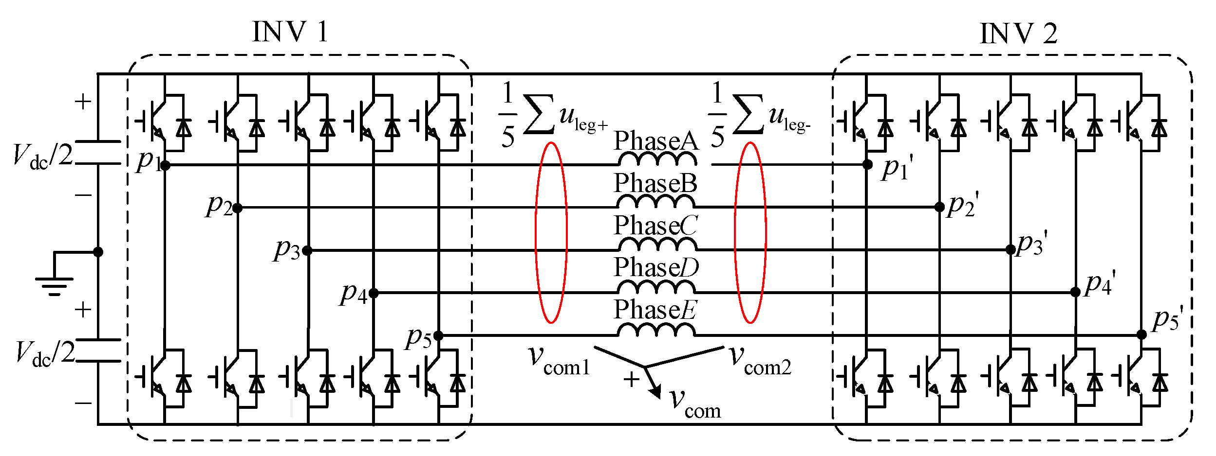
Hence, the open-winding inverter topologies have been employed in high-power application aeras like the wind power generation [10,11]. In high-reliability application aeras, open-winding six-phase motor system is designed for spacecraft [5] and EV applications [12,13] to handle the winding open-circuit and short-circuit faults. The structure of the open-winding drive topology with a single DC bus is shown in Figure 1.
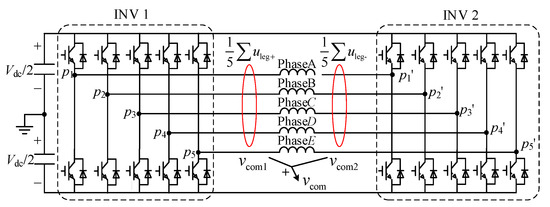
Figure 1.
Five-phase open-winding topologies and definition of the CMV.
CMV is one of the side effects in machine systems fed by pulse width-modulated inverters, which refers to the common components in all voltages applying to phase loads as shown in Figure 1. The high-amplitude and high-frequency CMV would obviously affect the safe operation of machine systems. For example, the shaft voltage is a replica of CMV in the open-winding inverter system, and their waveform are relatively similar under the traditional PWM scheme [14,15]. Suppression of the CMV can help to reduce the shaft voltage, decreasing the charge accumulation of air-gap capacitance to avoid the breakdown voltage on the lubricant around the bearings, thus avoid the electric discharge machining (EDM) currents which would shortening the bearing’s mechanical life. Additionally, large common-mode leakage currents appear when the CMV applies to the stray circuits, bringing about undesirable electromagnetic interference (EMI) which reduces the reliability of the system [16,17].
A large number of hardware and software solutions have been proposed to reduce the CMV. Among most hardware solutions, filters are employed in inverter topologies which increase the system’s size and weight cost. In constant, software solutions are more popular which aim to reduce the CMV with improved PWM methods. Most improved PWM methods are improved space vector pulse width modulation (SVPWM) methods, employing voltage vectors with low or zero CMV contribution. For the open-winding five-phase drive systems, voltage vectors with 2π/5 or 4π/5 phase displacement in two inverters are used in Refs. [18,19] to eliminate the CMV. To further reduce the current ripple caused by the utilization of the zero CMV voltage vectors, certain non-zero CMV are also employed in Ref. [20] to improve the current and torque quality of the motor, however, allowing a small quantity of the CMV. Though the above methods can effectively suppress the CMV, in total, 1024 voltage vectors exist in the open-winding 5-phase drive system, which makes the design and implementation of the improved SVPWM methods complex. Comparatively, improved CPWM methods are more straightforward and easier to apply. In Ref. [21], by symmetrically shifting phase angles of the carriers in two inverters with 2π/6, the CMV can be theoretically eliminated for the three-phase drive system. However, the CMV ripples appear in the experiment due to the ideal factors which are not given further analysis, and the effects of the carrier phase shift on the winding currents are not discussed. For the multi-phase drive system, Ref. [22] indicates that by symmetrically shifting the carrier phase angles with 2π/m, CMV can be completely eliminated in even m-phase inverters, but the CMV suppression effect deteriorates in odd m-phase inverters which is sensitive to the modulation index. In Ref. [23], opposite triangle carriers are applied to the second and fourth largest modulating waves to reduce 80% of the CMV peak-to-peak value. In Ref [24], two sets of sawtooth carriers are alternately employed in the odd-phase inverters, achieving the suppression of the amplitude and the step frequency of the CMV. However, the methods in Refs. [22,23,24] are all related to the half-bridge topologies. Hence, CMV characteristic and the current performance should be re-examined when applying them to open-winding inverters due to increased dimensions of the bridge legs and current paths.
Considering to the complexity of the improved SVPWM CMV suppression methods, this paper introduced two improved CPWM methods with the simple modification of phase angle and shape of the carriers, which can be easily applied to the multi-phase open-winding topologies. The CMV suppression effect, current quality, dead-time effect, and EMI characteristic of these two PWM method are analyzed and compared to give a comprehensive evaluation. The organization of this paper is as follows. Section 2 defines the CMV characteristics of the open-winding inverters. Principles of two improved CPWM methods are analyzed, with the comparison of their effects on the current quality. In Section 3, dead-time effects on the CMV suppression performance of two improved CPWM methods are investigated. Section 4 and Section 5 are the experiment verification and conclusion parts respectively.
2. Improved CPWM Methods with CMV Suppression Effects
2.1. CMV under Traditional CPWM
In open-winding topologies, the CMV can be calculated by summing all phase voltages in inverter 1 (INV 1) and inverter 2 (INV 2). Defining and are the switching functions of the bridge leg in the INV 1 and INV 2 (which equals 1 when the upper switch turns on and the lower one turns off, otherwise −1), the can be expressed in Equation (1).
In Equation (1), the first and second part right the equation are CMV contributions of INV 1 and INV 2 respectively, which can be defined as the sub CMV and as shown in Figure 1. Considering that the sum of the switching function has 11 possible values which ranges from −10 to 10 (with the step of 2), there are totally 11 possible CMV levels: , ,
, , and .
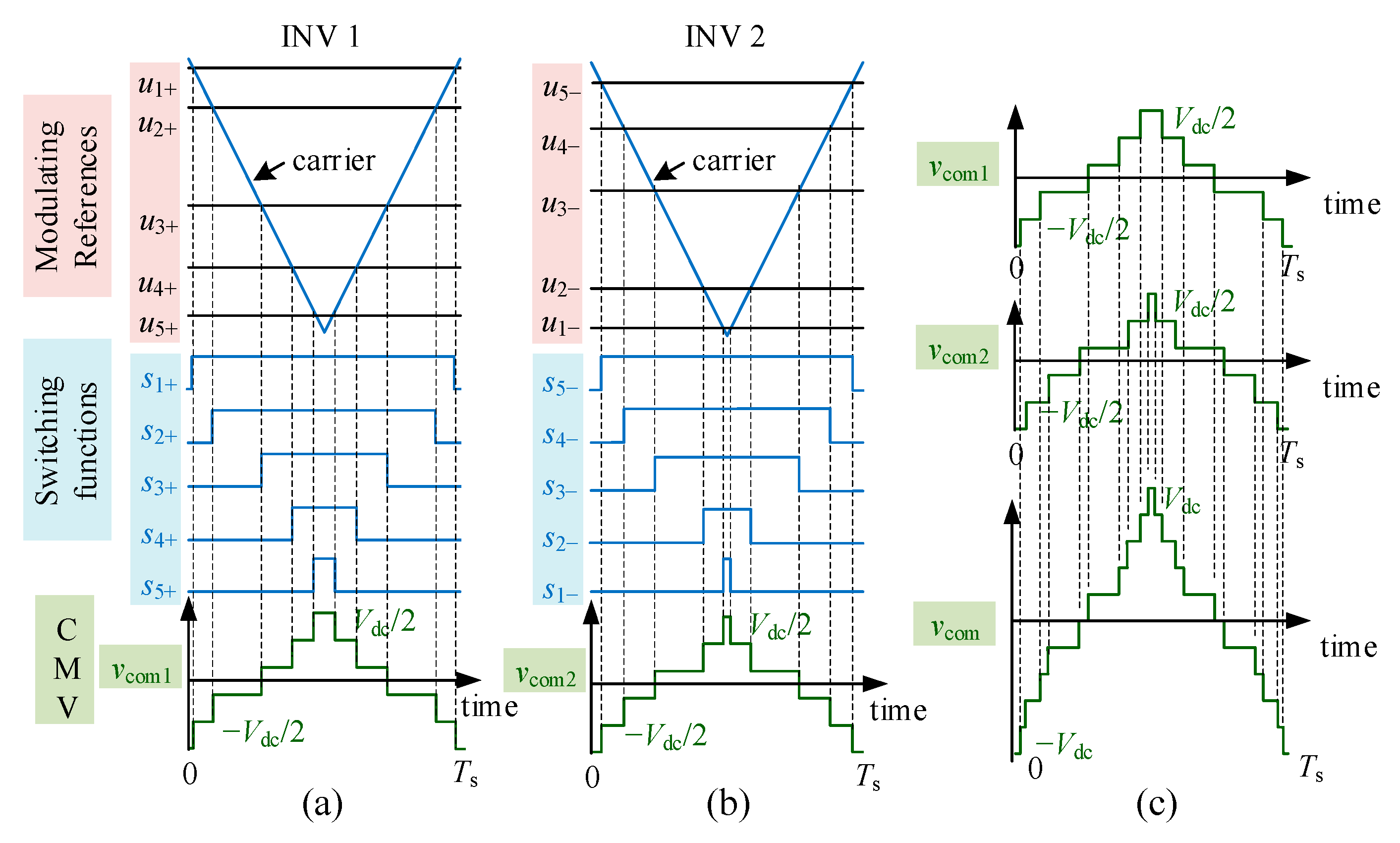
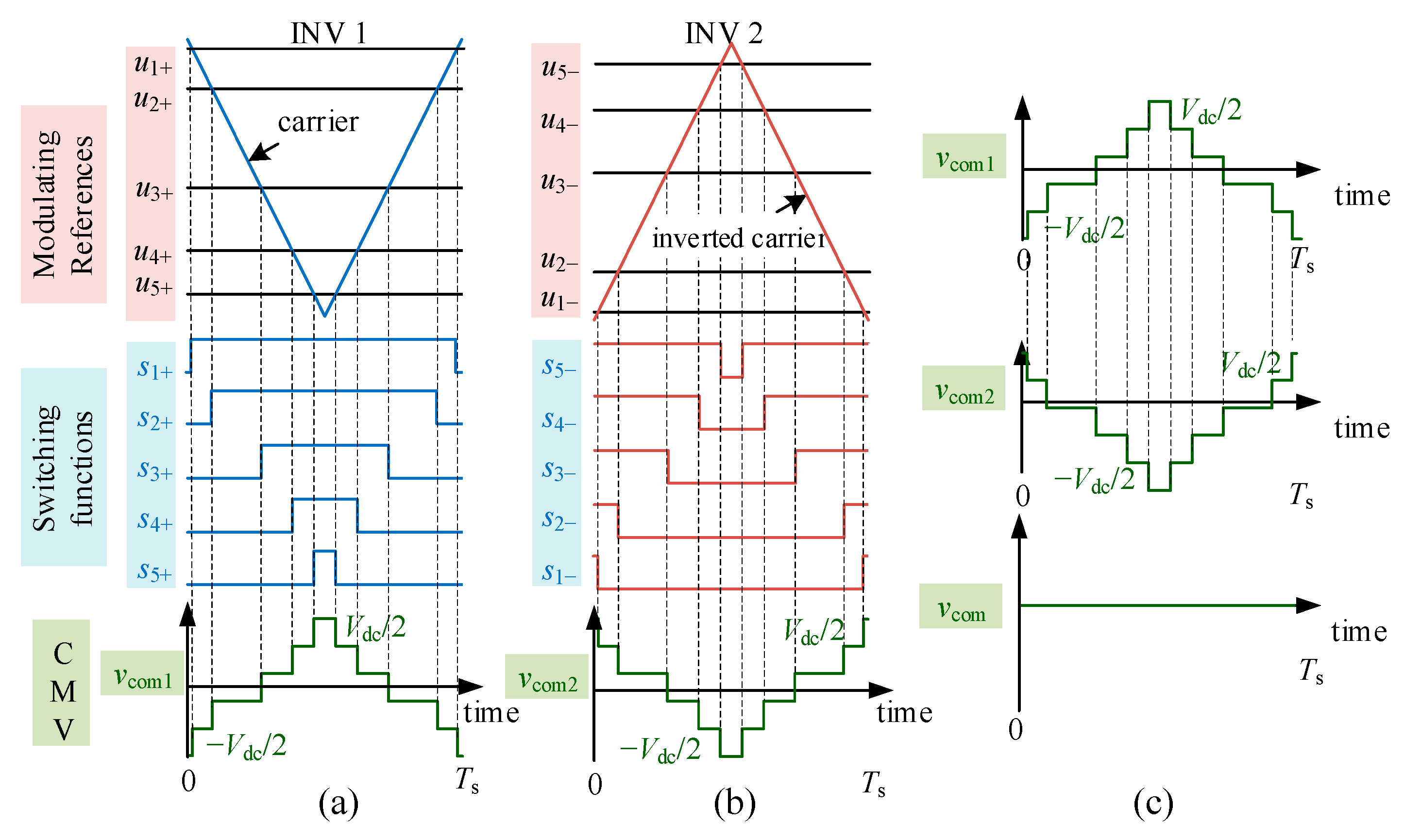
Under the traditional CPWM, voltage references in INV 1 and INV 2 are commonly antiphase to achieve the high DC voltage utilization rating. Carriers are uniform triangular waveforms. Hence, the CMV waveform under the traditional CPWM in a switching period is shown in Figure 2.
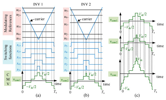
Figure 2.
Switching state in (a) INV 1, (b) INV 2 and the (c) CMV under the traditional CPWM.
As shown in Figure 2, switching function waveforms are centrally distributed due to the symmetrical triangular carriers, and centers of two sub CMVs, and , are symmetrical. After summing two sub CMVs, has 11 levels and steps 20 times in a switching period. reaches the maximum or minimum ( or ) when carriers reach the peak or valley values. Obviously, 11 possible levels and the theoretical maximum amplitude of CMV appear under the traditional CPWM.
2.2. CMV under Carrier-Reversed PWM
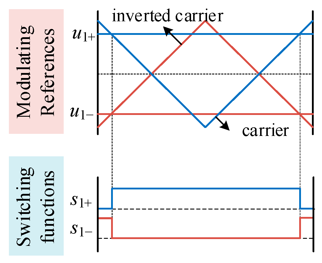
According to Equation (1), if −1 and 1 exist in pairs in switching functions, sum of the switching functions will equal zero, leading to zero CMV. Actually, this requirement can be easily satisfied in open-winding topologies. Considering that voltage references are inversed in two INVs, if reversed carriers are further employed for INV 2, switching functions of the bridge legs belonging to the same phase are always complementary, as shown in Figure 3. As a result, their CMV contributions are cancelled.
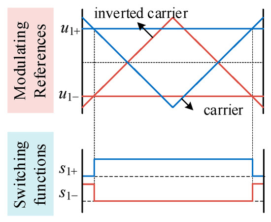
Figure 3.
Bridge leg voltages in INV 1 and INV 2 of the same phase under the CRPWM.
As shown in Figure 4, will be absolutely reversed compared to after employing reversed carriers for INV2, and the CMV can be entirely eliminated.
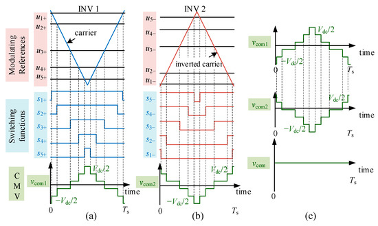
Figure 4.
Switching state (a) INV 1, (b) INV 2 and the (c) the CMV under the CRPWM.
Though the carrier reverse operation can effectively suppress the CMV, high-frequency harmonics of winding voltages will increase, effecting the quality of winding currents. Taking the phase A for example, Fourier analysis results of the bridge leg voltages in INV 1 and INV 2, and , under traditional CPWM are shown in Equations (2) and (3) respectively (assuming initial angles of the voltage reference and carrier is 0).
where is the modulation index. is the n-order Bessel function. and are the fundamental and the carrier angular velocities respectively.
Then, the winding voltage can be expressed as
Due to the factor in Equation (4), winding voltage harmonics which satisfy Equation (5) do not exist.
Obviously, only harmonics with the frequency of exist, where and are the fundamental and the carrier frequency respectively. There are no harmonics around the odd-order switching frequency.
Under the CRPWM, the initial angle of the carrier in INV2 changes to . The bridge leg voltage will be
Then, the winding voltage can be rewritten as
Comparatively, the harmonic factor becomes , and harmonics which satisfying Equation (8) do not exist.
It can be seen that the winding voltage simultaneously contains harmonics with the frequency of and . Voltage harmonics around the odd-order switching frequency appear. Consequently, the current harmonics around the switching frequency will increase, deteriorating the total harmonic distortion (THD) of the winding current.
2.3. CMV under Carrier-Switching PWM
Under CRPWM, winding currents would deteriorate significantly due to reversed carriers employed for the same phase. Different from the CRPWM, the CSPWM aims to create complementary states of switching functions inside the same INV, reducing the sub CMV to suppress the CMV.
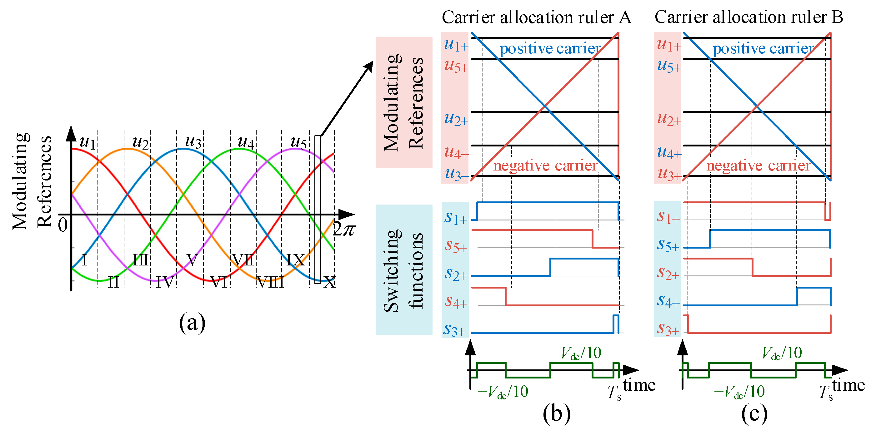
Under CSPWM, firstly, reversed carriers are employed for bridge legs with different up-down states, leading to reduced amplitude of sub CMV. Secondly, triangular carriers are replaced by sawtooth carriers to further reducing the step frequency of sub CMV, which is meaningful to reduce the CMV effects on the machine system [24]. As shown in Figure 5, five voltage references can be divided into 10 sectors in a fundamental period according to their up-down states. The carrier type of each bridge leg remains unchanged inside the sector, but changes when sector switches. Take the INV 1 in sector X for example, positive (right-slanting) sawtooth carriers are employed for rising voltage references , and , and negative (left-slanting) sawtooth carriers are employed for falling voltage references and . As a result, switching pulses of phase A, B and C have right side distributions, meanwhile that of phase D and E have left side distributions. It ensures the sum of switching functions in INV 1 varies between ± 1. Hence, the amplitude of declines to , which is 1/5 of that under the traditional CPWM. Additionally, comparison operations of the carrier waveform and the reference waveform occur on the single edge of the sawtooth carrier, leading to reduced CMV step times, which is 6 in a switching period (10 times under the traditional CPWM).

Figure 5.
The (a) sectors distribution and the sub CMV under carrier allocation (b) ruler A and (c) ruler B.
It should be noted if reverse the carrier allocation rule, the same sub CMV suppression effect can still be achieved as shown in Figure 5c. The allocation rule in Figure 5b is defined as allocation ruler A here, and that in Figure 5c is defined as allocation ruler B.
When apply CSPWM in open-winding topologies, there are totally four different schemes according to the carrier allocation rule as shown in Table 1.

Table 1.
CSPWM schemes with different carrier allocation rules.
Under CSPWM 1 and 2, INV 1 and INV 2 adopt the same carrier allocation ruler. Because voltage references in INV 1 and INV 2 of the same phase are antiphase, their up-down states are reversed. Their carrier types are always reversed. Hence, similar to the CRPWM, CMV under CSPWM 1 and 2 can be eliminated, and high-frequency harmonics of phase currents also deteriorate significantly. Considering that implementations of CSPWM 1 and 2 are more complex compared with CRPWM due to the carrier switching operation, they are not valuable CMV suppression schemes.
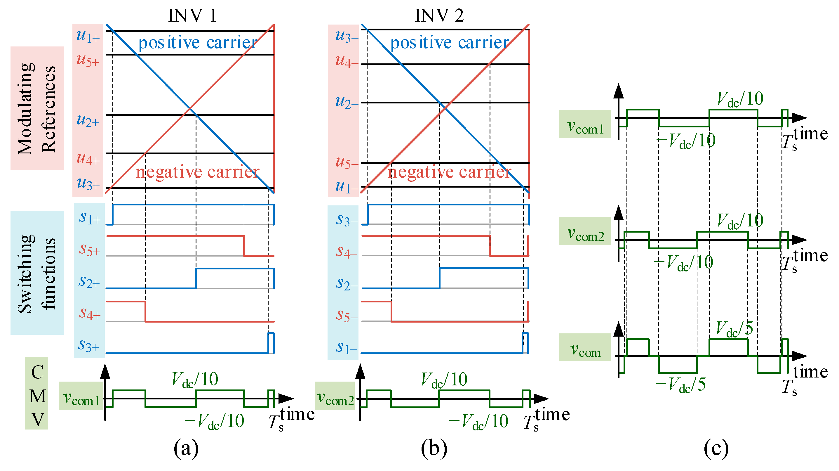
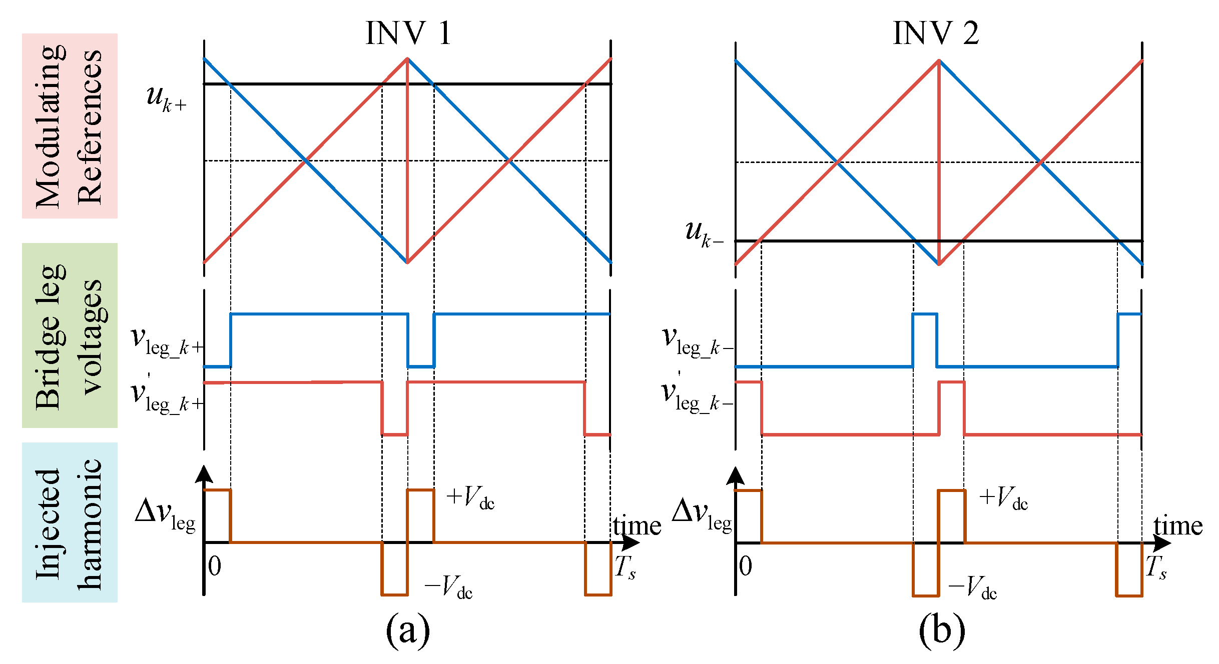
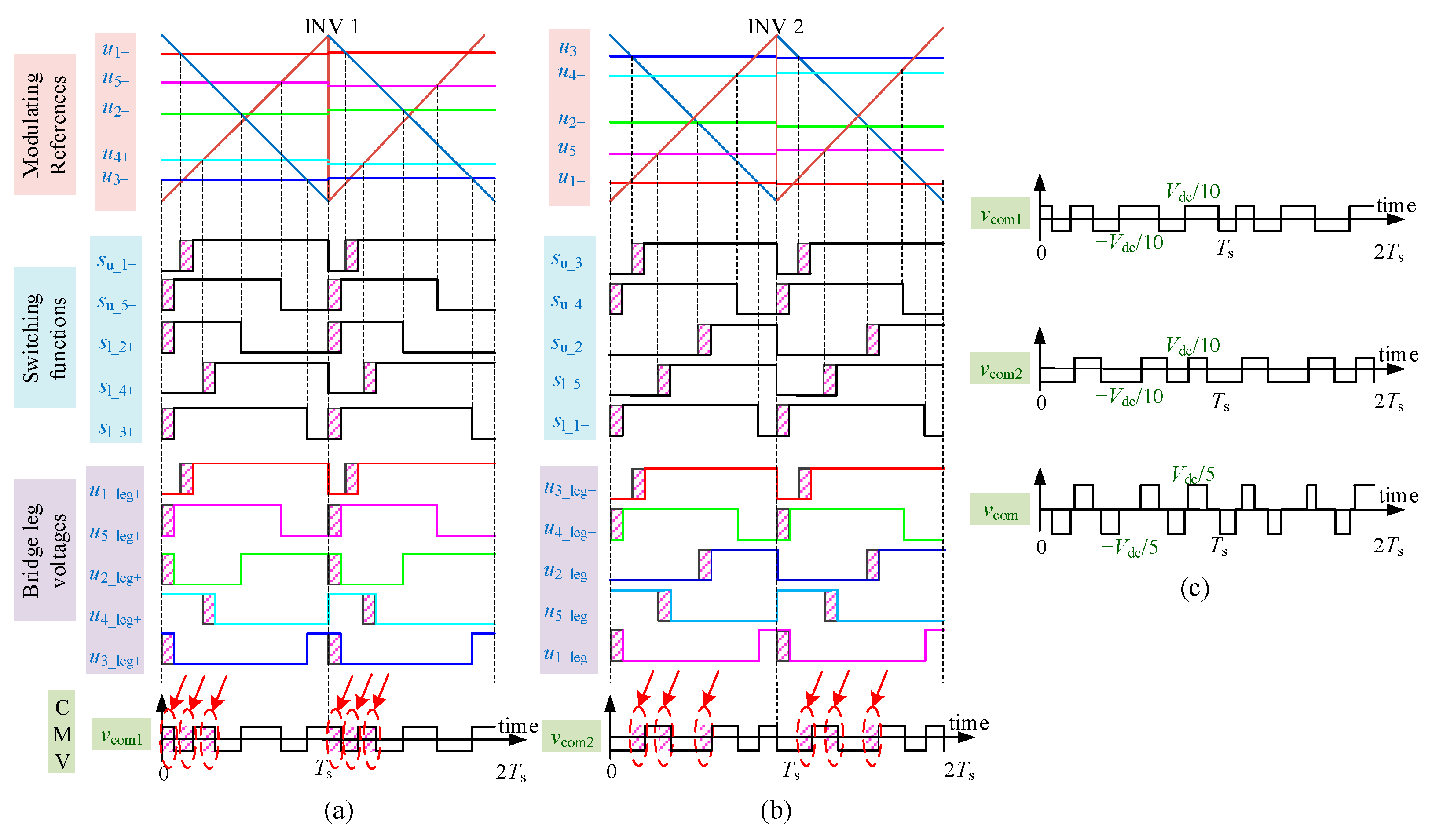
Under CSPWM 3 and 4, INV 1 and INV 2 adopt different carrier allocation rulers. Carriers in INV 1 and INV 2 of the same phase keep consistent. Take sector X for example as shown in Figure 6, sub CMVs and can both be suppressed within . The amplitude of can be suppressed to and its step times decline to 11, which are 20% and about 50% respectively compared with that under traditional CPWM.
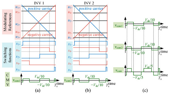
Figure 6.
Switching state in (a) INV 1, (b) INV 2 and the (c) CMV under the CRPWM.
Carriers in INV 1 and INV 2 of the same phase keep consistent under CSPWM 3 and 4, which will not cause significant high-frequency current harmonics like that under CRPWM. However, it is necessary to discuss the effects of the carrier switching operation on current quality.
Firstly, in a switching period, bridge leg voltages in INV 1 and INV 2 of phase k before and after the carrier switching operation, and , are shown in Figure 7. It can be seen that value of is consistent with that of . It indicates the injected voltage harmonics in the and are the same after the carrier switching operation.
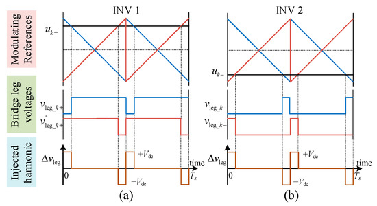
Figure 7.
Comparison of the bridge leg voltages after the carriers switching in (a) INV 1 and (b) INV 2.
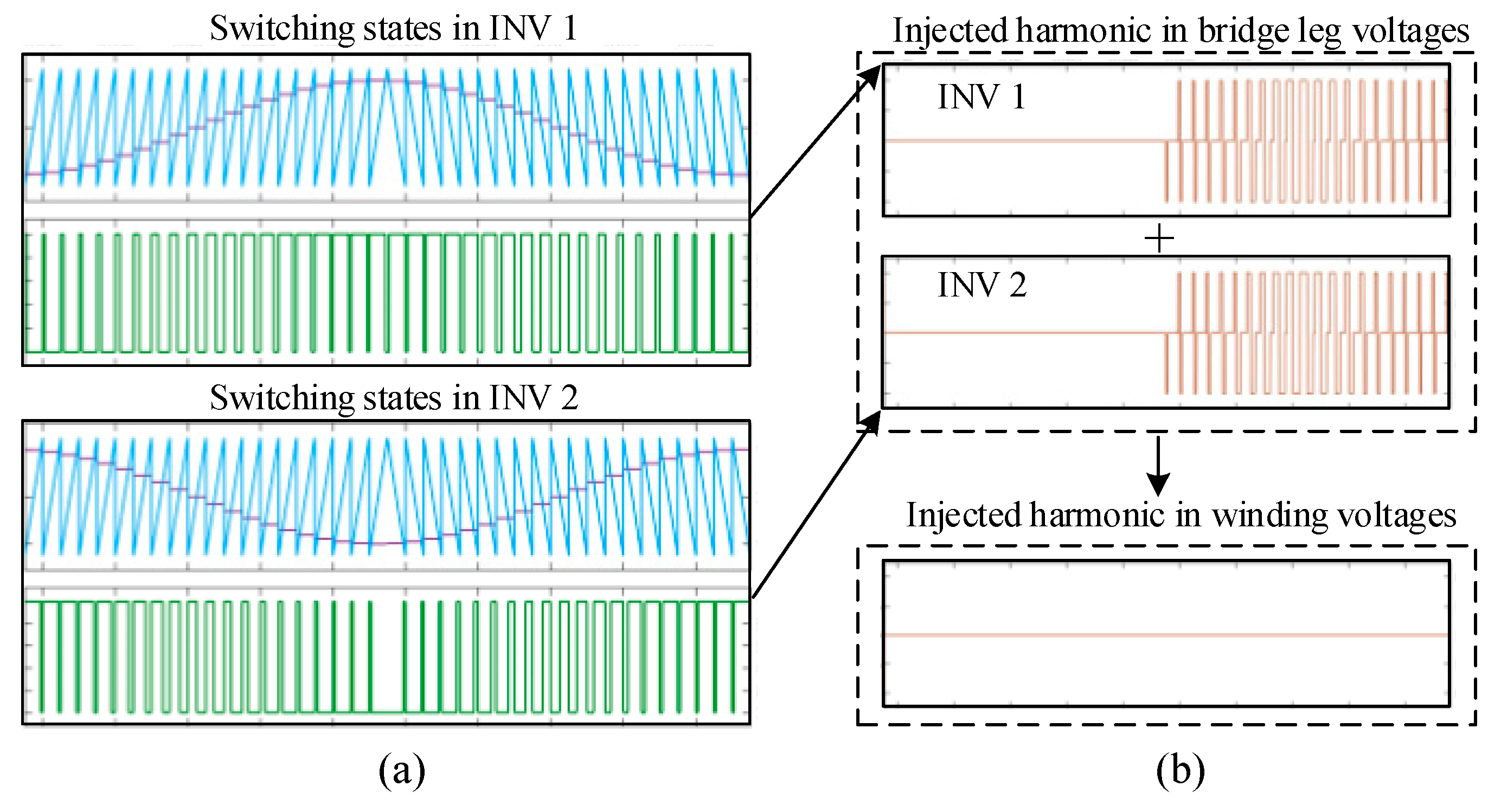
Further, in a fundamental period, carriers in INV 1 and INV 2 of phase k will switch at the same time due to the antiphase voltage references as shown in Figure 8. Hence, consistent harmonics will be injected into and simultaneously, which causes no voltage difference on the winding. Consequently, carrier switching operations under CSPWM do not affect the winding current quality.

Figure 8.
The (a) PWM state in two inverters and (b) injected harmonics of the bridge legs voltage and the winding voltage.
As a conclusion, CSPWM 3 and 4 are CMV suppression schemes which compromise CMV suppression effects and the winding current quality. It should be noted that the CSPWM 3 and CSPWM 4 are actually equivalent with no essence difference. In the following sections, CSPWM 3 is regarded as a representative of CSPWM with further discussion and investigation.
3. Dead-Time Effects on CMV Suppression
The above sections analysis the CMV in ideal conditions, supposing the bridge voltage waveform is consistent with the switching function. Actually, the turn-on and turn-off processes of the switches cannot complete instantaneously. Dead time delay is required at rising edges of the switching functions to avoid short-circuit problems. The dead time delay will cause phase shift of the bridge voltage pulses, which might break their complementary states and then affect the CMV suppression effects of the improved PWM methods. In this section, the dead-time effects on CMV suppression are analyzed.
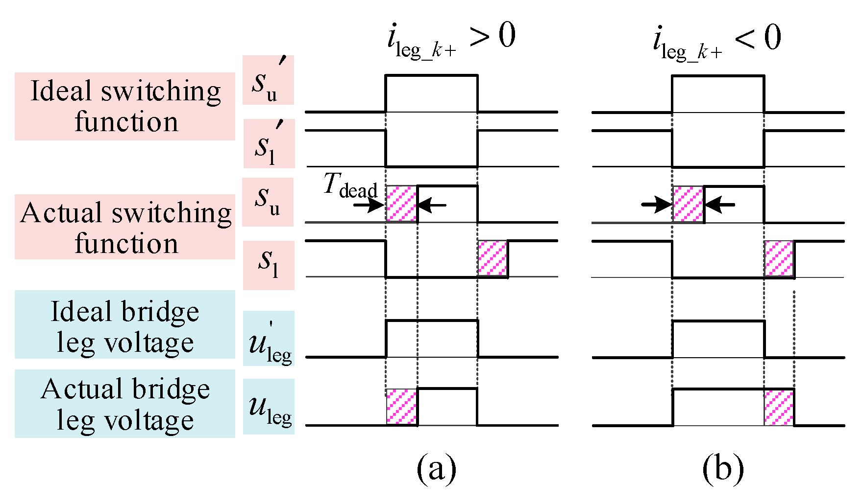
As shown in Figure 9,
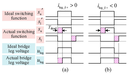
Figure 9.
Dead-time effects on the bridge leg voltages when (a) and (b) .
- (1)
- if (define the bridge leg current when it flows out of the bridge leg, otherwise ), when the upper switch turns on, flows through the upper switch and the bridge leg equals . When the upper switch turns off, flows through the lower diodes and equals . That is, waveform of the bridge leg voltage is consistent with the upper switch’s function .
- (2)
- if , when the lower switch turns on, will flow through the lower switch and the bridge leg equals . When the lower switch turns off, flows through the upper diodes and equals . That is, waveform of the bridge leg voltage is the inversion of its lower switch’s function .
3.1. Dead-Time Effects in Carrier-Reversed PWM
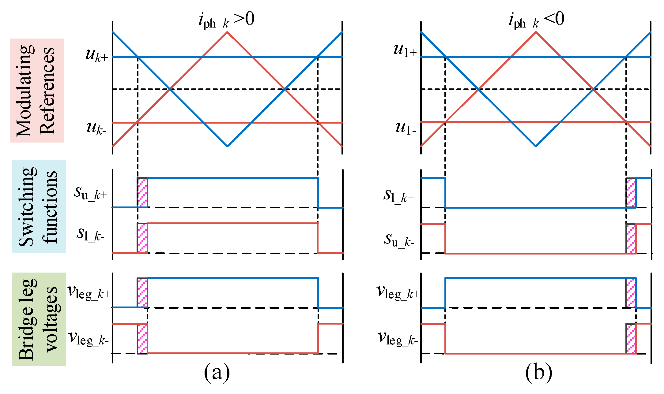
With the above analysis, bridge legs voltages and under CRPWM are as shown in Figure 10. When the winding current , there will be and . Hence, the waveform of is consistent with , and the waveform of is the inversion of as shown in Figure 10a. Obviously, edges of and are shifted simultaneously and the complementary state remains.
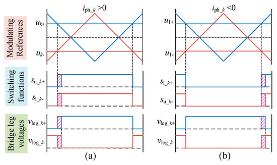
Figure 10.
Complementation state of bridge leg voltages of the same phase with the dead-time effects when (a) and (b) .
Similarly, the complementary state of and remains when as shown in Figure 10b. CMV contributions of the bridge legs belonging to the same phase can still be cancelled. The dead-time delay will not affect the CMV suppression effect of CRPWM.
3.2. Dead-Time Effects of Carrier-Switching PWM
In Ref [24], dead-time effects of CSPWM on the CMV are analyzed for half-bridge topologies. In this section, dead-time effects on the CMV for open-winding topologies are further analyzed. Discussions of dead-time effects on CMV under CSPWM can be divided into two parts.
- (1)
- dead-time effects in the switching period without carrier changing
Under CSPWM 3, allocation ruler A and B are adopted respectively in INV 1 and INV2. As analyzed in Ref. [24], under both allocation ruler A and B, only step edges of some sub CMV pulses will be shifted due to the dead time delay. Take sector X for example, in INV 1, rising voltage references and employ positive carriers, and falling employ negative carriers. With the inductive characteristic of the motor load, it is assuming and . Hence, the bridge leg voltages and sub CMV in INV 1 are shown in Figure 11a. Shifted edges of are marked by red circle. The amplitude and step times of are still and 11 respectively in a switching period. Similarly, waveform of can be obtained as shown in Figure 11b. When summing and , the amplitude and step times of are unchanged as shown in Figure 11c.
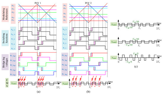
Figure 11.
Dead-time effects on the sub CMV in (a) INV 1, (b) INV 2 and the (c) CMV in the switching period without carriers switching under CSPWM 3.
- (2)
- dead-time effects in the switching period with carrier changing
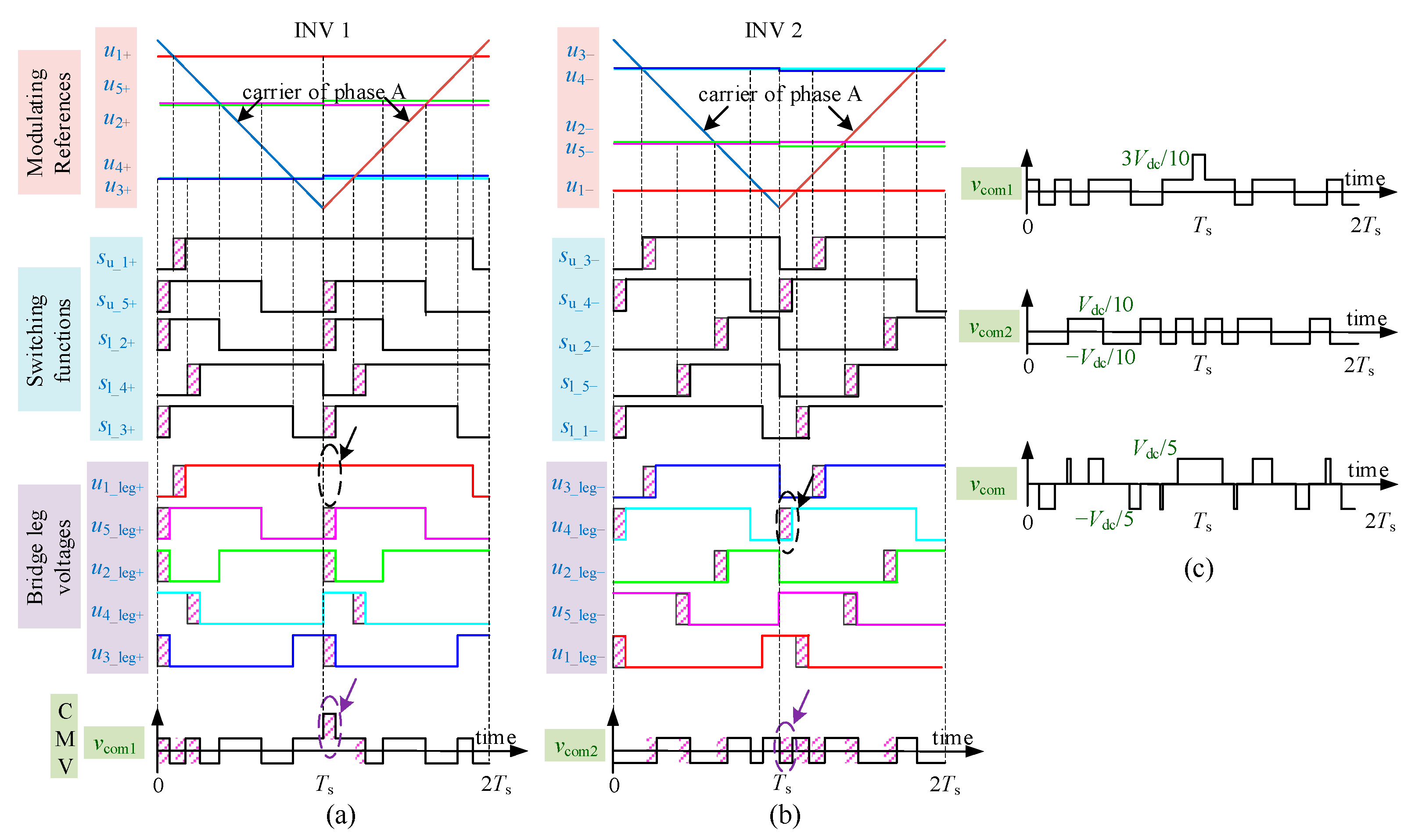
When the sector switches, dead-time ripples of sub CMV will appear in the inverter which adopts the carrier allocation ruler A [24]. Assuming the sector switches from sector X to sector I, as shown in Figure 12, the up-down state of phase A voltage reference changes, and the carrier of phase A changes from the positive triangular waveform to the negative one in two inverters simultaneously. In INV 1, it leads to a disappeared low voltage level in the bridge voltage of phase A (marked by black cycle). Hence, a ripple in appear (marked by purple cycle) which reaches and lasts a dead time . However, in INV 2, the bridge leg voltage of phase D is low at the same time due to the dead-time delay. It causes a low CMV level in , which can opportunely cancel the ripple in . After summing and , the amplitude of still do not exceed and its step times remain unchanged.
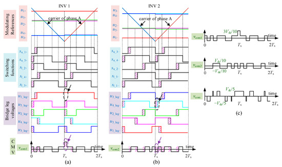
Figure 12.
Dead-time effects on the sub CMV in (a) INV 1, (b) INV 2 and the (c) CMV in the switching period with carriers switching under CSPWM 3.
As a conclusion, in open-winding topologies, the dead-time delay might cause ripples in sub CMVs and shift the edges of some CMV pulses, but do not affect the CMV suppression effects.
4. Experiment Verification
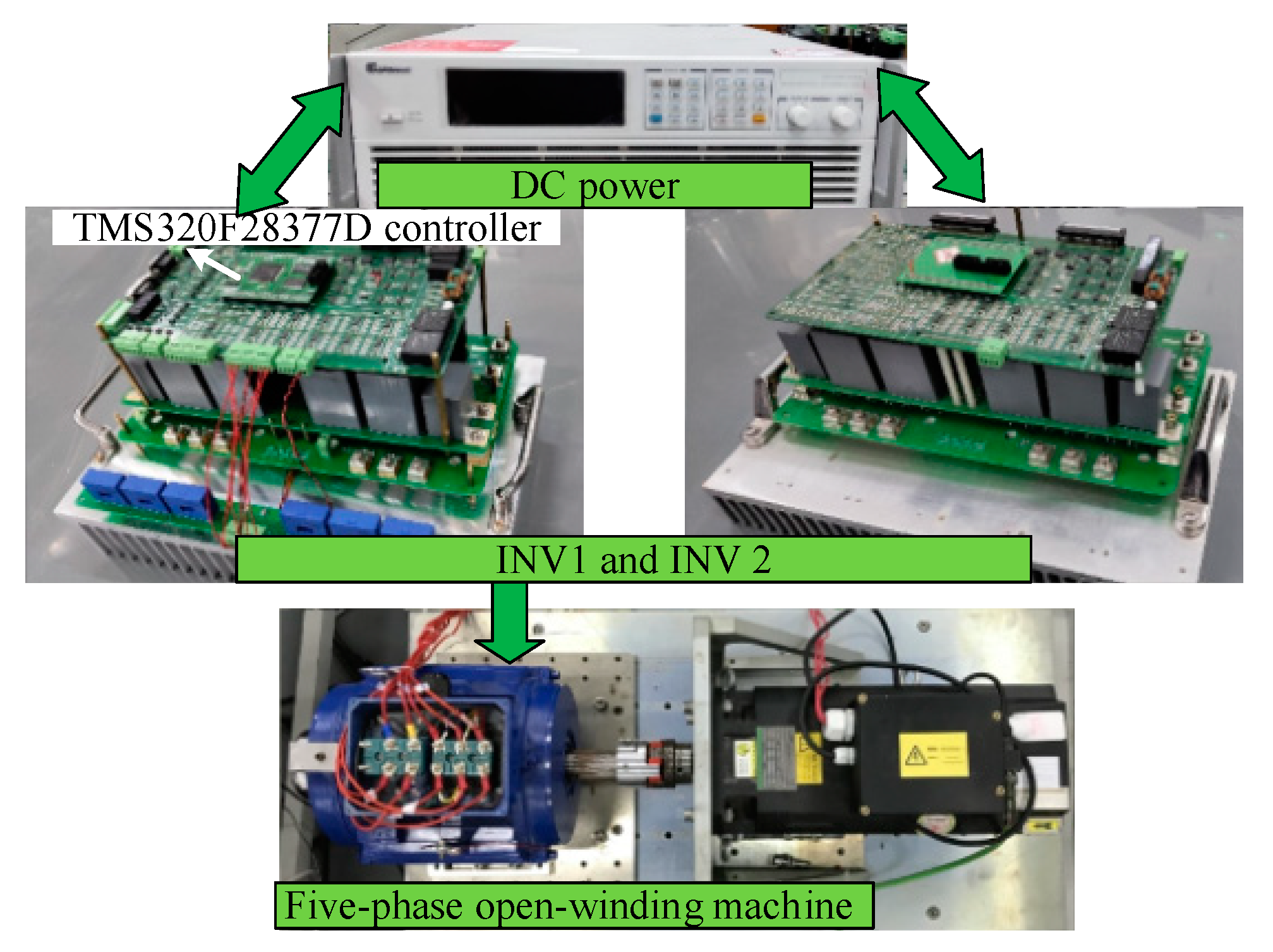
In this part, experiments are implemented on an open-winding five-phase machine system whose photograph is shown in Figure 13. INV 1 and INV 2 both have six bridge legs and ten of them are employed here, which are controlled by one same Digital Signal Processor (DSP TMS320F28377). Parameters of the induction machine and the experiments setting are listed in Table 2. It should be noted that due to the limited testbed, the CMV, winding currents and EMI characteristics are tested and compared in this part; however, the shaft voltage and bearing current issues are not examined.

Figure 13.
Photograph of the experiment platform.
Table 2.
Parameters of the machine and experiment settings.
4.1. CMV Comparison under Different PWM Methods
In this part, the machine operates at the speed of 1500 rpm with on load. Since there is no winding neutral point in open-winding topologies, the CMV cannot be measured directly. Considering that the shell voltage will be induced due to the CMV, whose waveform is almost identical to the CMV, but the amplitude slightly declines, the shell voltage is measured here to reflect the CMV.
The winding current of phase A and the shell voltage under the traditional PWM are shown in Figure 14. Obviously, the CMV has 11 levels and steps 20 times with the amplitude of 80 V. After employing the CRPWM method, the shell voltage is effectively suppressed whose amplitude is close to zero.
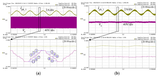
Figure 14.
Winding current and shell voltage under the traditional CPWM (a) and the CRPWM (b).
The shell voltage under the CSPWM 3 is shown in Figure 15. Clearly, varies between three levels with the amplitude of 16 V and step 11 times in a switching period, which declines 80% and about 50% corresponding the analysis in Section 2.3. Additionally, there appears no dead-time ripple in .
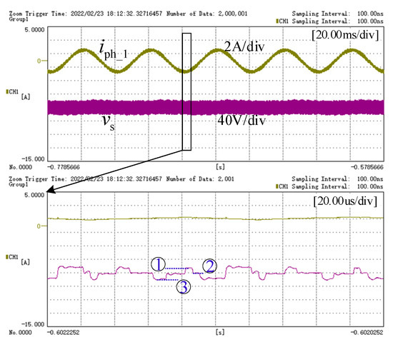
Figure 15.
Winding current and shell voltage under the CSPWM.
4.2. Comparison of the Current Quality under Different PWM Methods
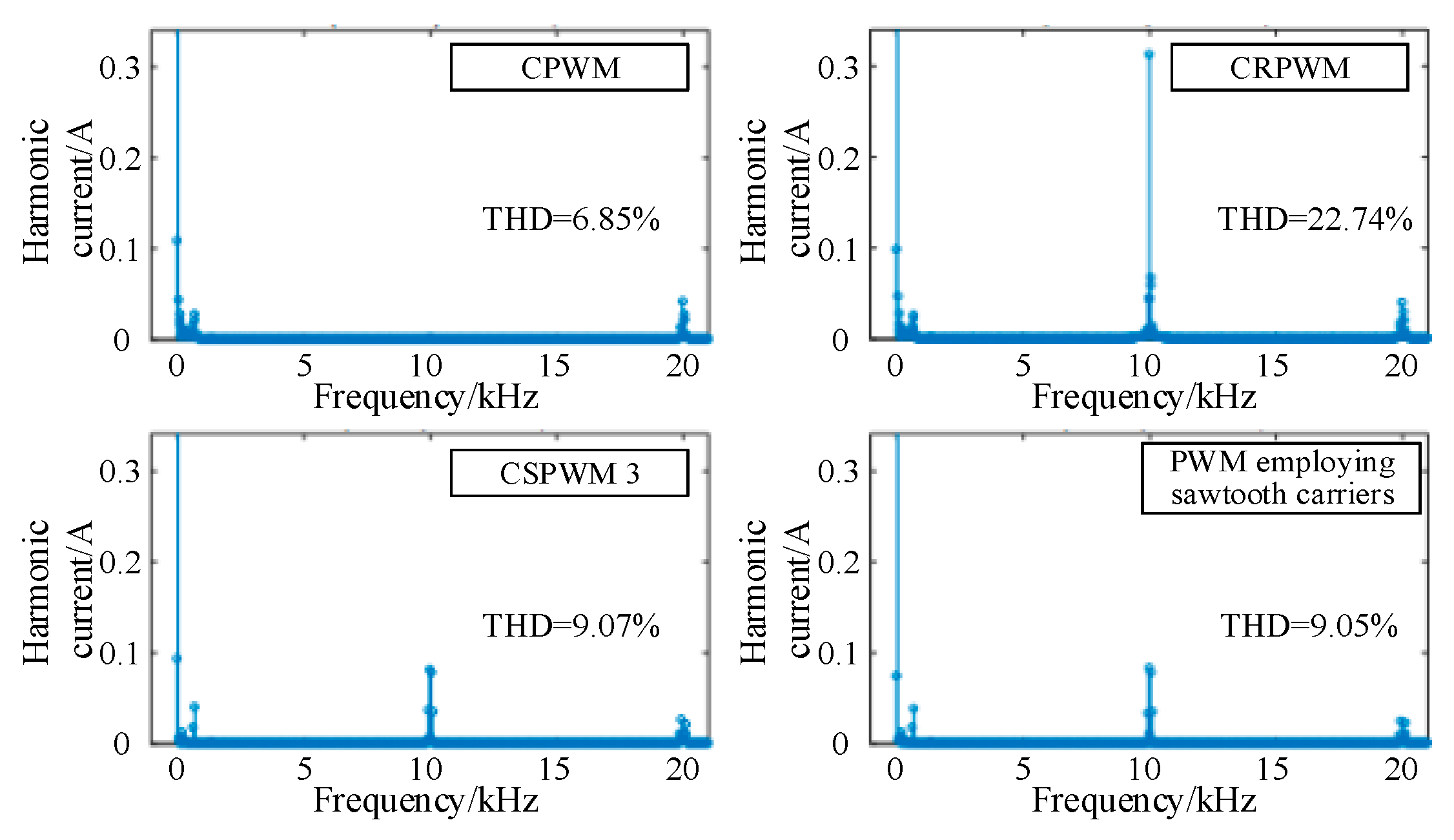
As shown in Figure 14 and Figure 15, the current deteriorates obviously under the CRPWM, and the level of current ripples under the traditional PWM and CSPWM 3 are closed. The current fast Fourier transform (FFT) results under the above three PWM methods are shown in Figure 16. Additionally, the current FFT result under the PWM method in which unchanged sawtooth carriers employed is also shown in Figure 16, to show the carrier switching effects on the current quality.
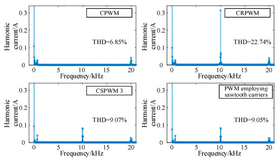
Figure 16.
FFT results of the winding current under different PWM methods.
It can be seen that, compared with the traditional CPWM methods, the current harmonics near the switching frequency (10 kHz) increases significantly under the CRPWM, whose maximum amplitude increases from 0.002A to 0.32 A, and the current THD increases from 6.85% to 22.74%. Under the CSPWM and the PWM employing unchanged sawtooth carriers, current FFT results are highly consistent. Their THD are 9.07% and 9.05% respectively. It verifies the conclusion that carrier switching operations do not affect the current harmonics. However, due to the employment of sawtooth carriers, the amplitude of current harmonic around 10 kHz slightly increases by 0.08 A compared with that under the traditional CPWM method. The THD increases by 2.22%.
4.3. Common-Mode EMI (CM EMI) Characteristic Comparison under Different PWM Methods
The system CM EMI characteristics under different PWM methods are further tested here. In the experiment, the DC power are in series with two line impedance stabilization networks (NNBM 8126 A890, 0.1–150 MHz, 600 V, 100 A) to isolate the noise from the DC power. A piece of copper sheet (2000 × 1200 × 0.50 mm) are utilized to provide a common ground for two inverters and the machine. The frequency spectrum of the conducted CM EMI ranging from 150 kHz to 30 MHz is tested with the EMI receiver Rohde-Schwarz ESL 3.
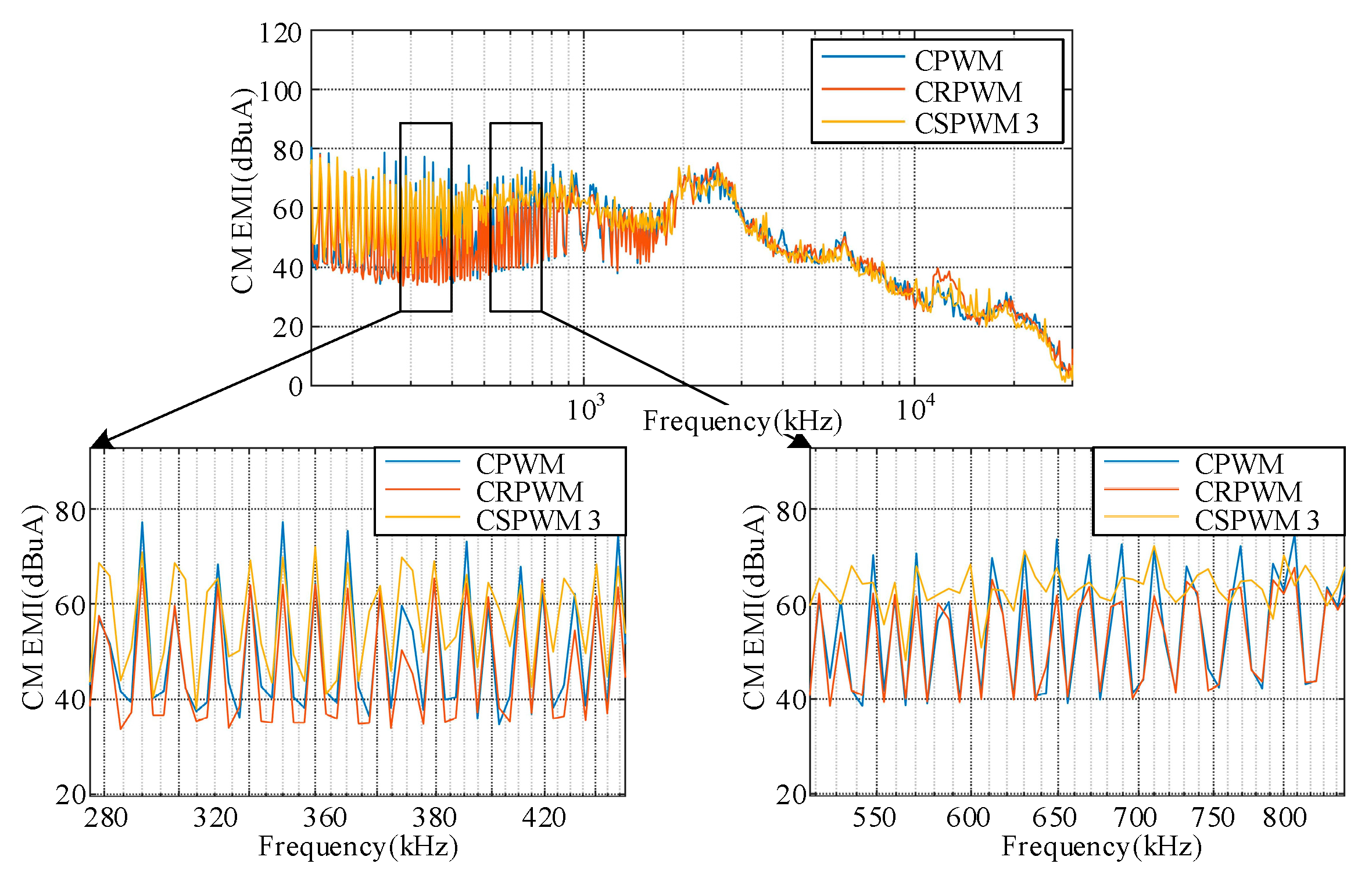
As shown in Figure 17, CM EMI characteristics under different PWM methods show obvious differences within 10 MHz. Generally, the CM EMI is at the highest level under the traditional CPWM, and at the middle level under the CSWPM. With the eliminated CMV, the EMI characteristic is the most optimal under CRWPM.
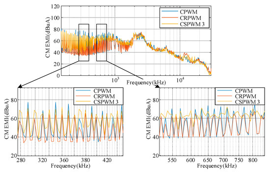
Figure 17.
CM EMI characteristics under different PWM methods.
Table 3 shows the comparison of CM EMI peaks in different frequency bands. In the frequency bands of 200 kHz–300 kHz, 300 kHz–500 kHz and 500 kHz–1 MHz, compared with the traditional CPWM, the CM EMI peaks under the CSWPM decreases by 5.27 , 5.24 and 2.14 respectively, and that under the CRPWM decreases by 7.74 , 11.89 and 7.00 . In the frequency band beyond 10 MHz, differences of CM EMI under different PWM methods are not obvious.
Table 3.
CM EMI peaks in different frequency band under different PWM methods.
5. Conclusions
This paper introduces two improved carrier-based PWM methods with the CMV suppression effect for the five-phase open-winding topologies. Conclusions of this paper are as follows.
- (1)
- Compared with the traditional CPWM, by employing reversed carriers for the INV2, the CMV can be eliminated under the CRPWM. Due to dynamically switching of the inverted carriers under the CSPWM, sub CMV in two inverters can be effectively suppressed, leading to an 80% and 50% decline of the CMV amplitude and step times.
- (2)
- Under the CRPWM, odd-order high frequency harmonics increase, and winding currents clearly deteriorate. Under the CSPWM, current distortion is slight due to the employment of sawtooth carriers. The CSPWM is a compromise method between the CMV suppression effect and the current quality.
- (3)
- The dead-time delay does not affect the CMV suppression effects of the CRPWM method. Under the CSPWM, ripples and low voltage level caused by the dead-time delay exist in pairs in sub CMVs, and the suppression effects of CMV amplitude and step times remain unchanged.
Author Contributions
Conceptualization, Z.L. and J.T.; methodology, Z.L. and D.J.; software, P.W. and P.L.; validation, P.W.; formal analysis, D.J. and P.L.; investigation, Z.L.; resources, J.T.; data curation, Z.L.; writing—original draft preparation, P.W.; writing—review and editing, Z.L. and J.T.; supervision, D.J. and P.L. All authors have read and agreed to the published version of the manuscript.
Funding
This research received no external funding.
Institutional Review Board Statement
Do not require ethical approval.
Informed Consent Statement
Not applicable.
Data Availability Statement
Not applicable.
Conflicts of Interest
The authors declare no conflict of interest.
Abbreviations
| CPWM | carrier-based pulse width modulation |
| CRPWM | carrier-reversed PWM |
| CSPWM | carrier-switching PWM |
| SVPWM | space vector pulse width modulation |
| CMV | common-mode voltage |
| EDM | electric discharge machining |
| EMI | electromagnetic interference |
| INV | inverter |
| FFT | fast Fourier transform |
| THD | total harmonic distortion |
References
- Levi, E. Multiphase electric machines for variable-speed applications. IEEE Trans. Ind. Electron. 2008, 55, 1893–1909. [Google Scholar] [CrossRef]
- Peng, X.; Liu, Z.; Jiang, D. A review of multiphase energy conversion in wind power generation. Renew. Sustain. Energy Rev. 2021, 147, 111172. [Google Scholar] [CrossRef]
- Liu, Z.; Fang, L.; Jiang, D.; Qu, R. A Machine-Learning-Based Fault Diagnosis Method with Adaptive Secondary Sampling for Multiphase Drive Systems. IEEE Trans. Power Electron. 2022, 37, 8767–8772. [Google Scholar] [CrossRef]
- Sadeghi, S.; Parsa, L. Design and dynamic simulation of five phase interior permanent magnet machine for series hybrid electric vehicles. In Proceedings of the 2010 IEEE Green Technologies Conference, Grapevine, TX, USA, 15–16 April 2010; pp. 1–6. [Google Scholar]
- Xu, J.; Zhang, B.; Fang, H.; Guo, H. Guaranteeing the fault transient performance of aerospace multiphase permanent magnet motor system: An adaptive robust speed control approach. CES Trans. Elect. Mach. Syst. 2020, 4, 114–122. [Google Scholar] [CrossRef]
- Song, Z.; Hu, S.; Zhang, R. Performance improvement of open winding PMSMs with a discrete-time designed zero-sequence current controller based on virtual three-phase expansion. IEEE Trans. Ind. Electron. 2020, 67, 10046–10054. [Google Scholar] [CrossRef]
- Somasekhar, V.T.; Gopakumar, K.; Baiju, M.R.; Umanand, L. A multilevel inverter system for an induction motor with open-end windings. IEEE Trans. Ind. Electron. 2005, 52, 824–836. [Google Scholar] [CrossRef]
- Kim, J.; Jung, J.; Nam, K. Dual-inverter control strategy for high-speed operation of EV induction motors. IEEE Trans. Ind. Electron. 2004, 51, 312–320. [Google Scholar] [CrossRef]
- Mu-Shin, K.; Seung-Ki, S. Control of an open-winding machine in a grid-connected distributed generation system. IEEE Trans. Ind. Appl. 2008, 44, 1259–1267. [Google Scholar]
- Zhu, L.; Zhang, F.; Jin, S.; Ademi, S.; Su, X.; Cao, W. Optimized Power Error Comparison Strategy for Direct Power Control of the Open-Winding Brushless Doubly Fed Wind Power Generator. IEEE Trans. Sustain. Energy 2019, 10, 2005–2014. [Google Scholar] [CrossRef]
- Sun, B.; Chen, Z.; Gao, C.; Haddad, A.; Liang, J.; Liu, X. A Power Decoupling Control for Wind Power Converter Based on Series-Connected MMC and Open-Winding PMSG. IEEE Trans. Ind. Electron. 2022, 69, 8091–8101. [Google Scholar] [CrossRef]
- Wu, F.; Zheng, P.; Sui, Y.; Yu, B.; Wang, P. Design and Experimental Verification of a Short-Circuit Proof Six-Phase Permanent-Magnet Machine for Safety Critical Applications. IEEE Trans. Magn. 2014, 50, 8204304. [Google Scholar] [CrossRef]
- Liu, H.B.; Yang, H. Design of Six-Phase Fault-Tolerant Permanent Magnet Synchronous Motor Used in Electric Vehicle. Small Spec. Electr. Mach. 2019, 47, 47–51. [Google Scholar]
- Kalaiselvi, J.; Srinivas, S. Bearing Currents and Shaft Voltage Reduction in Dual-Inverter-Fed Open-End Winding Induction Motor With Reduced CMV PWM Methods. IEEE Trans. Ind. Electron. 2015, 62, 144–152. [Google Scholar] [CrossRef]
- Kalaiselvi, J.; Srinivas, S. Hybrid PWMs for shaft voltage reduction in a dual inverter fed induction motor drive. In Proceedings of the Proceedings of the IEEE International Conference on Industrial Technology, Cape Town, Western Cape, South Africa, 25–28 February 2013; pp. 539–544. [Google Scholar]
- Erdman, J.M.; Kerkman, R.J.; Schlegel, D.W.; Skibinski, G.L. Effect of PWM inverters on AC motor bearing currents and shaft voltages. IEEE Trans. Ind. Appl. 1996, 32, 250–259. [Google Scholar] [CrossRef]
- Akagi, H.; Shimizu, T. Attenuation of conducted EMI emissions from an inverter-driven motor. IEEE Trans. Power Electron. 2008, 23, 282–290. [Google Scholar] [CrossRef]
- Reddy, B.V.; Somasekhar, V.T. An SVPWM scheme for the suppression of zero-sequence current in a four-level open-end winding induction motor drive with nested rectifier–inverter. IEEE Tran. Ind. Electron. 2016, 63, 2803–2812. [Google Scholar] [CrossRef]
- Somasekhar, V.T.; Gopakumar, K.; Shivakumar, E.G. A space-vector modulation scheme for a dual two-level inverter fed open-end winding induction motor drive for the elimination of zero-sequence currents. EPEJ 2002, 12, 1–19. [Google Scholar] [CrossRef]
- Karampuri, R.; Jain, S.; Somasekhar, V.T. Phase displaced SVPWM technique for five-phase open-end winding induction motor drive. In Proceedings of the 2016 IEEE Students’ Conference on Electrical, Electronics and Computer Science (SCEECS), Bhopal, India, 5–6 March 2016; pp. 1–6. [Google Scholar]
- Kumar, G.N.; Srinivas, S. Carrier based PWM methods for CMV elimination in open-end winding induction motor drive. In Proceedings of the 2018 IEEE 12th International Conference on Compatibility, Power Electronics and Power Engineering (CPE-POWERENG), Piscataway, NJ, USA, 10–12 April 2018. [Google Scholar]
- Liu, Z.; Zheng, Z.; Sudhoff, S.D.; Gu, C.; Li, Y. Reduction of common-mode voltage in multiphase two-level inverters using SPWM with phase-shifted carriers. IEEE Trans. Power Electron. 2016, 31, 6631–6645. [Google Scholar] [CrossRef]
- Xiong, W.; Sun, Y.; Su, M.; Zhang, J.; Liu, Y.; Yang, J. Carrier-based modulation strategies with reduced common-mode voltage for five-phase voltage source inverters. IEEE Trans. Power Electron. 2018, 33, 2381–2394. [Google Scholar] [CrossRef]
- Liu, Z.; Wang, P.; Sun, W.; Shen, Z.; Jiang, D. Sawtooth carrier-based PWM methods with common-mode voltage reduction for symmetrical multiphase two-level inverters with odd phase number. IEEE Trans. Power Electron. 2021, 36, 1171–1183. [Google Scholar] [CrossRef]


Publisher’s Note: MDPI stays neutral with regard to jurisdictional claims in published maps and institutional affiliations. |
© 2022 by the authors. Licensee MDPI, Basel, Switzerland. This article is an open access article distributed under the terms and conditions of the Creative Commons Attribution (CC BY) license (https://creativecommons.org/licenses/by/4.0/).