
Photovoltaic Energy Storage System Based on Bidirectional LLC Resonant Converter Control Technology


Abstract
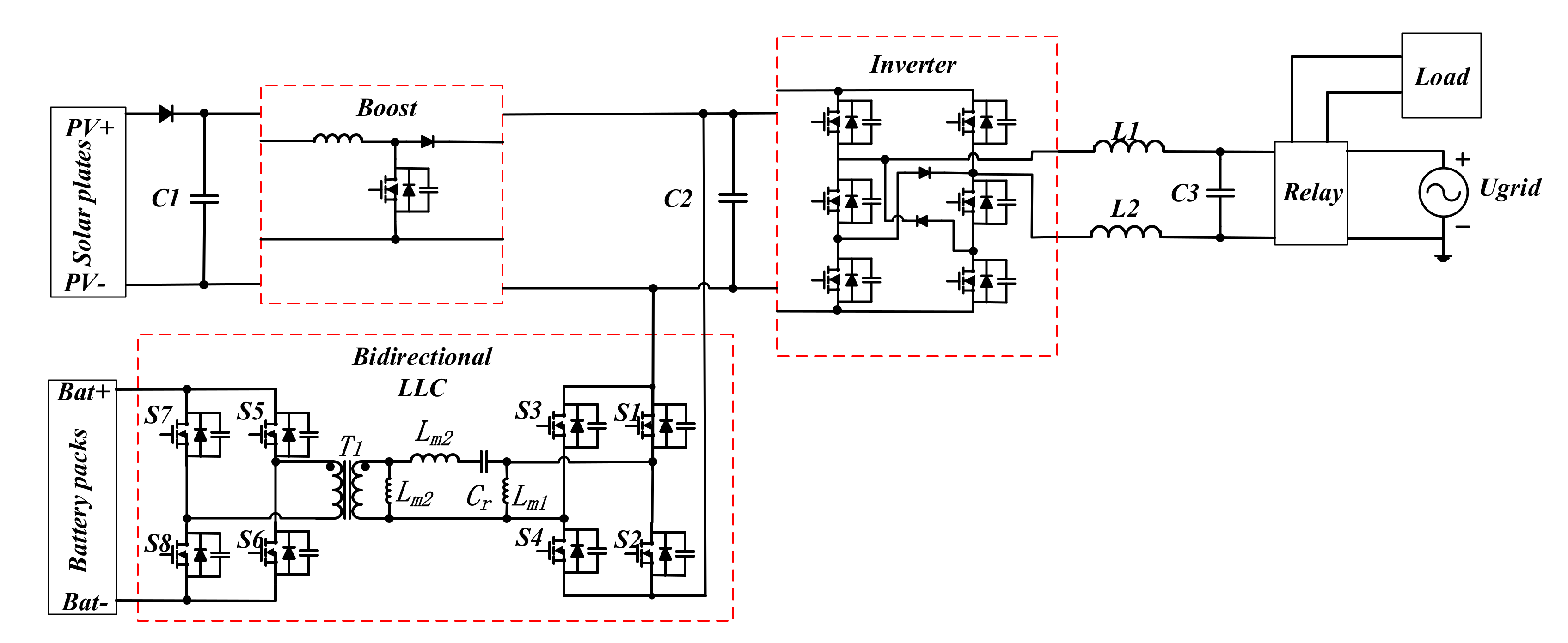
:1. Introduction
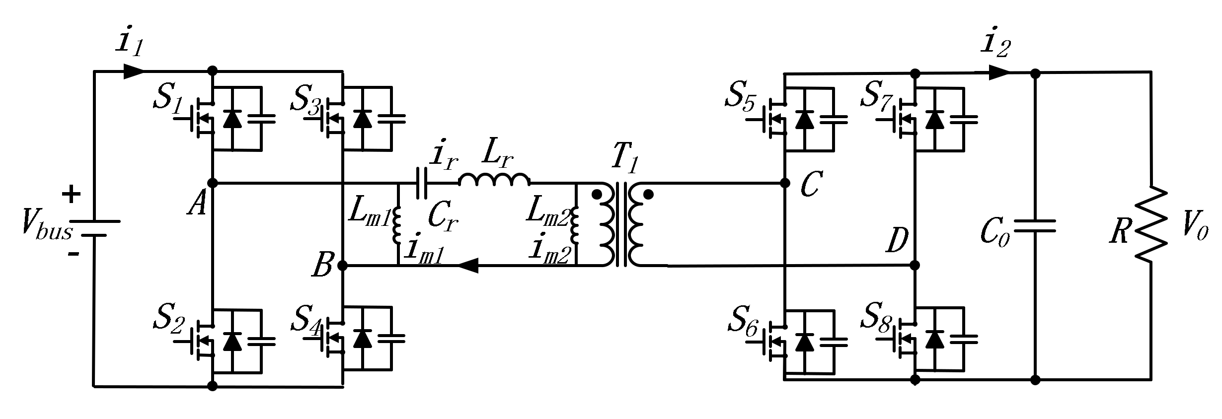
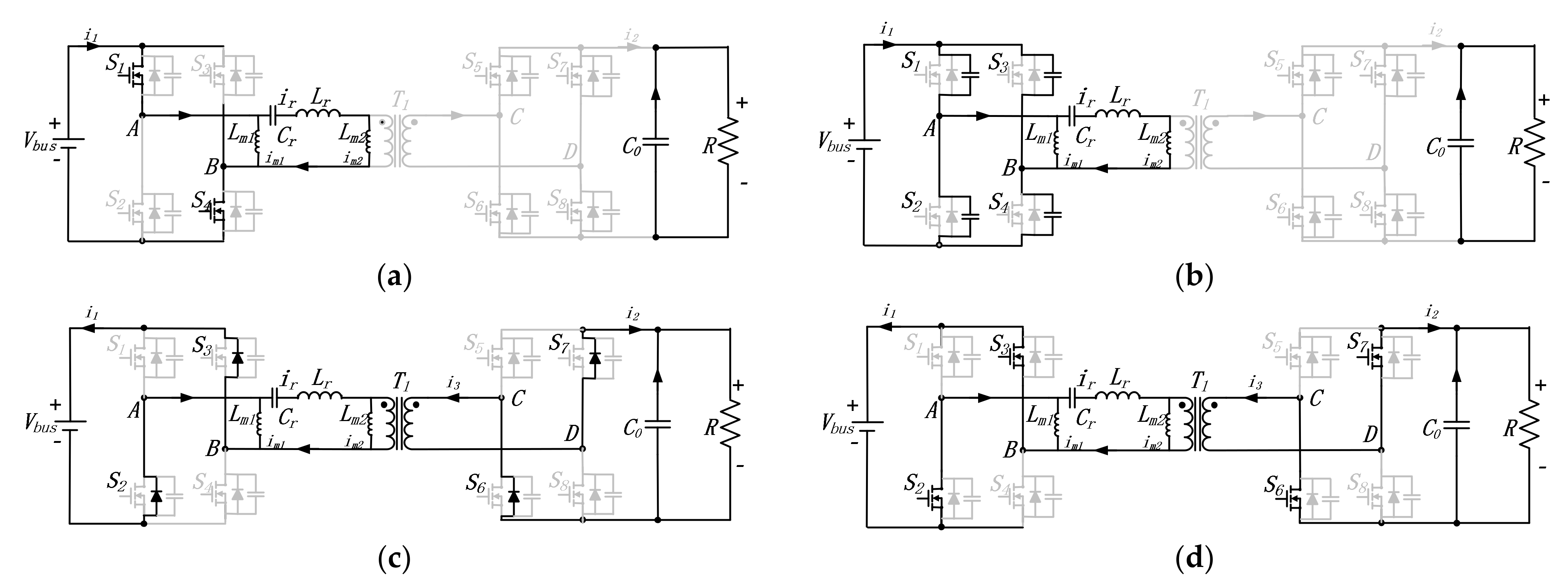
2. Operation Principle of Bidirectional LLC Resonant Converter
3. Characteristics Analysis of Bidirectional LLC Resonant Converter
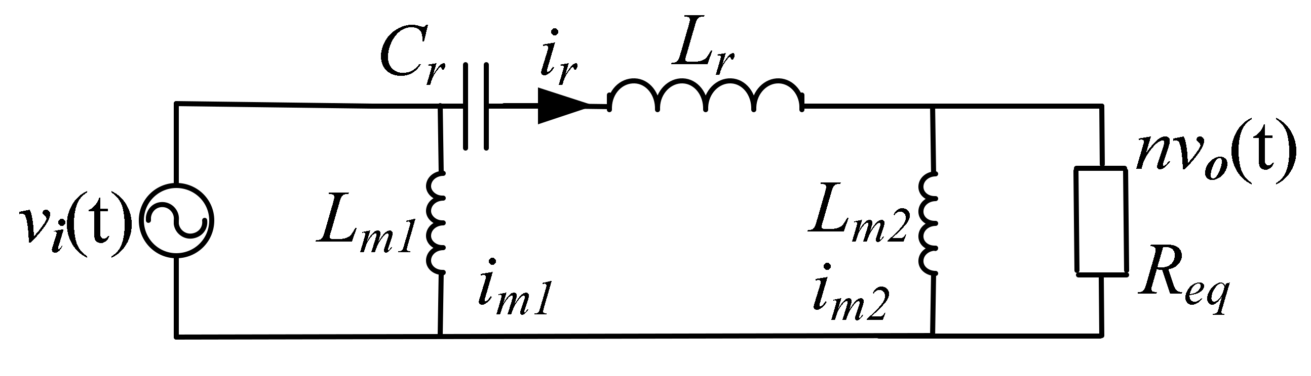
3.1. Analysis of Voltage Gain
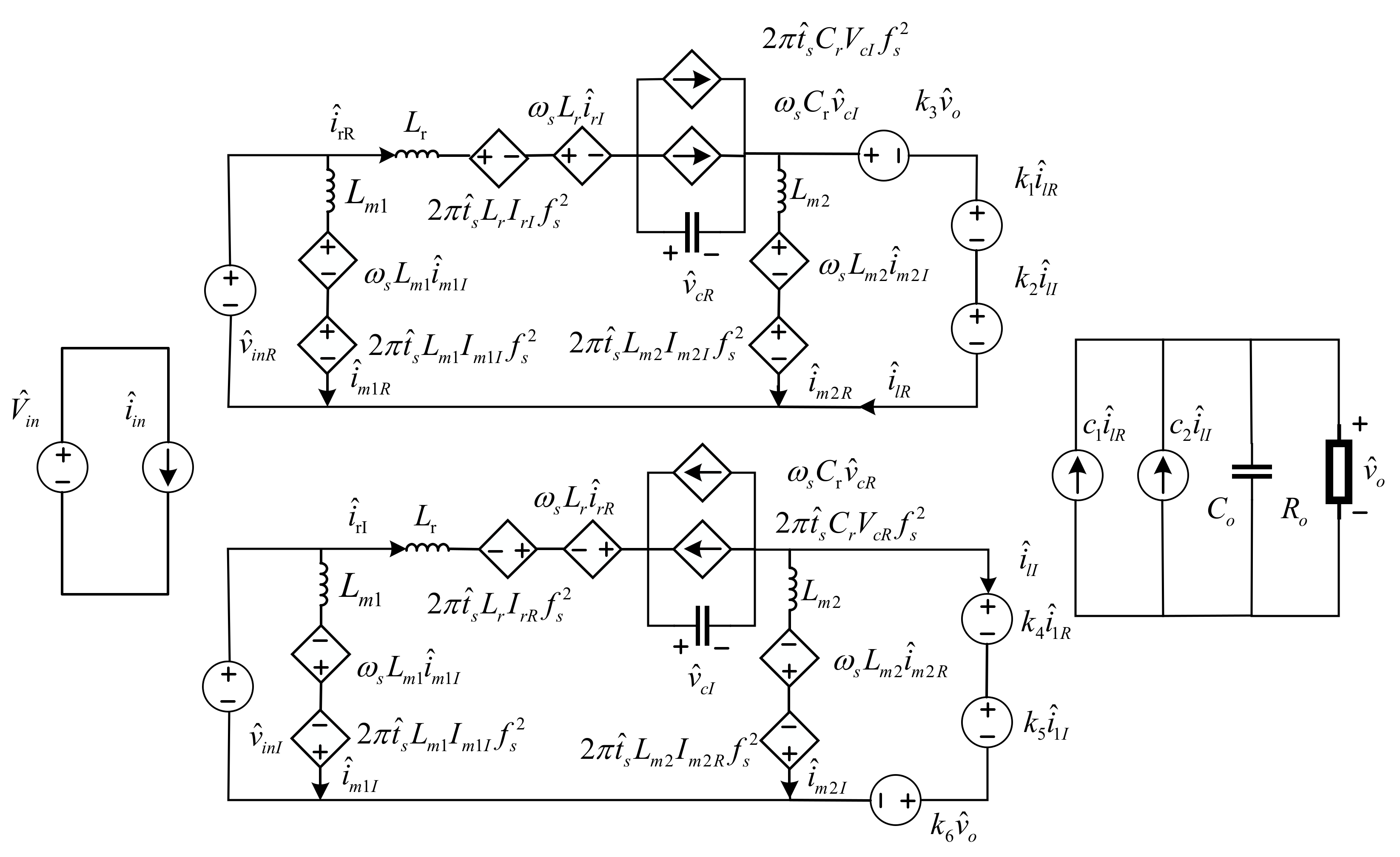
3.2. Small Signal Analysis
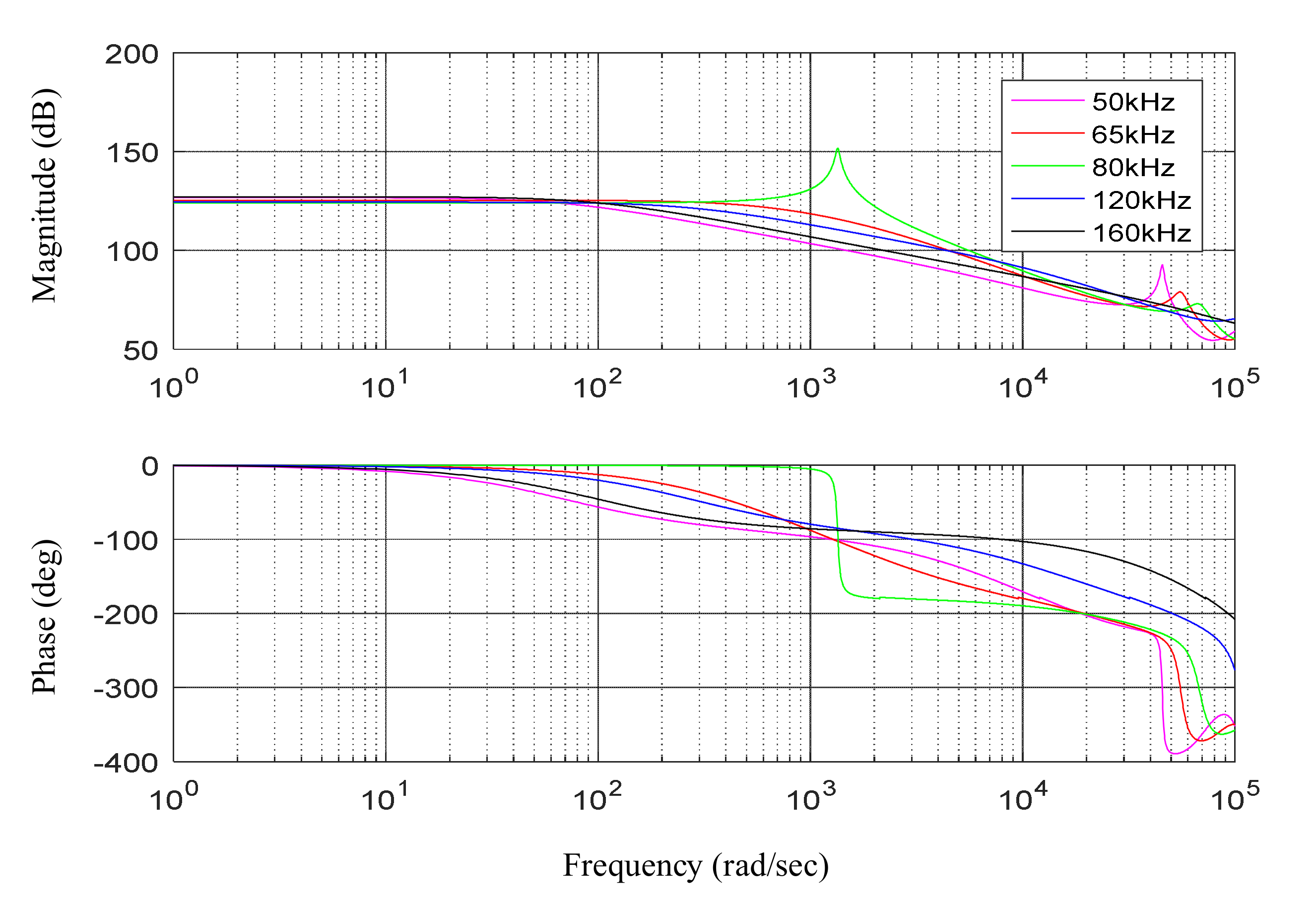
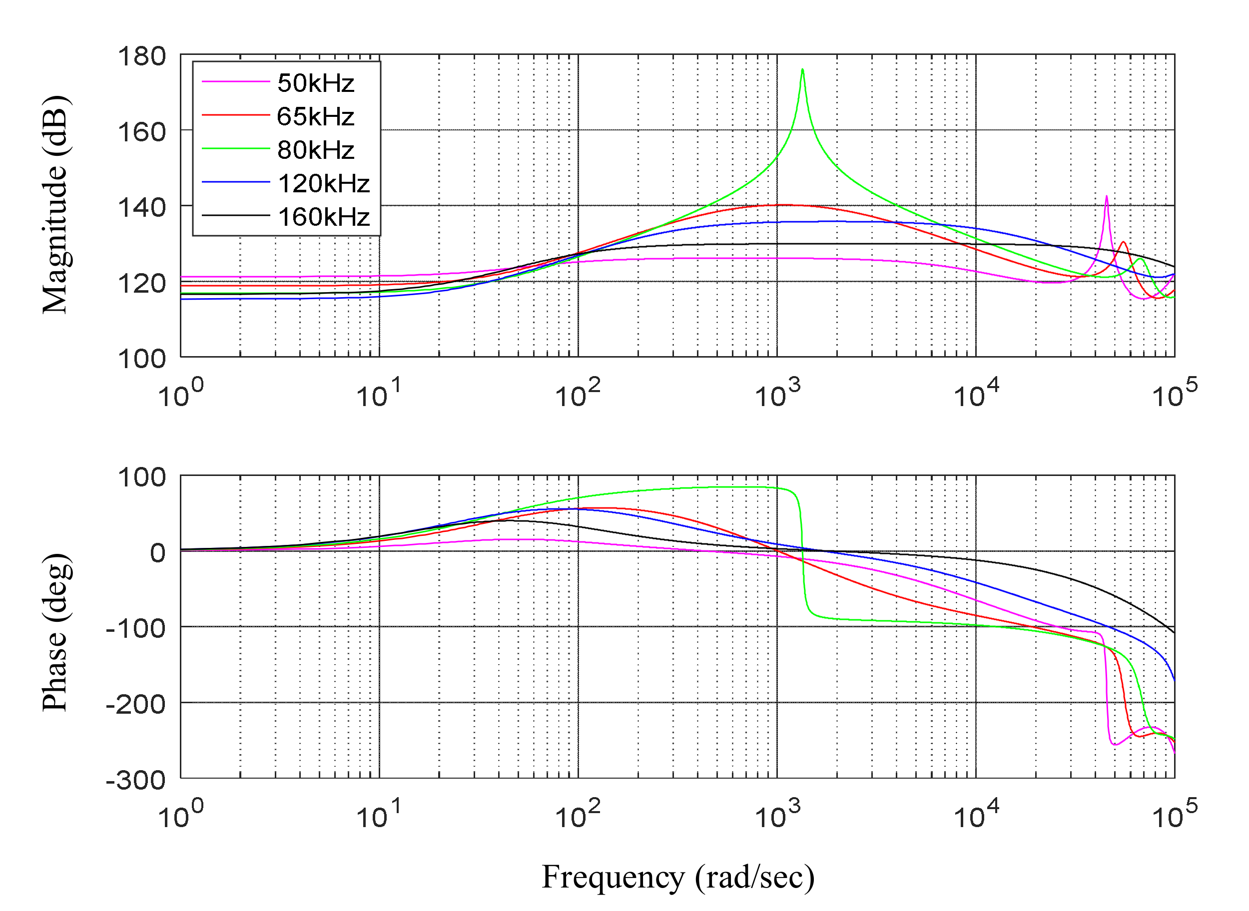
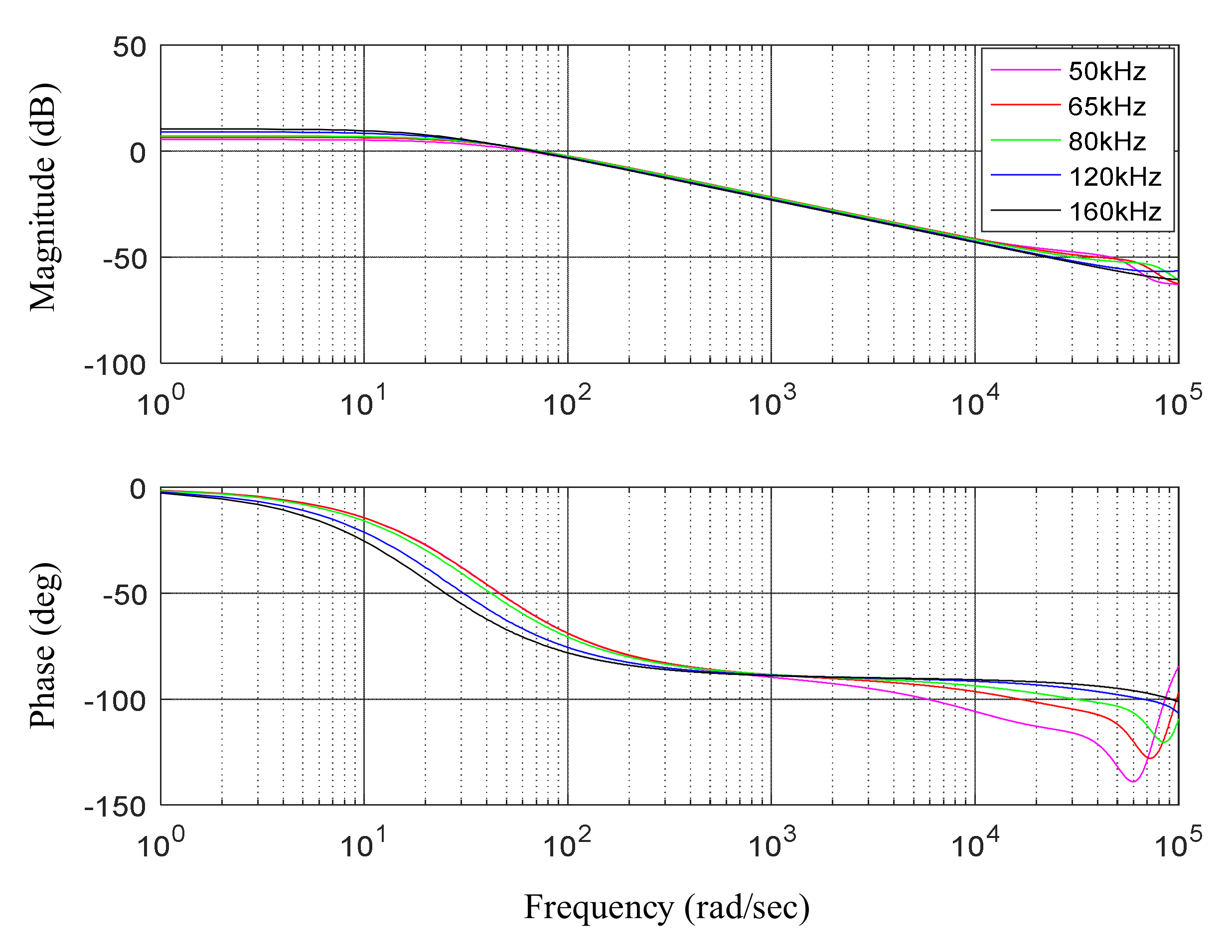
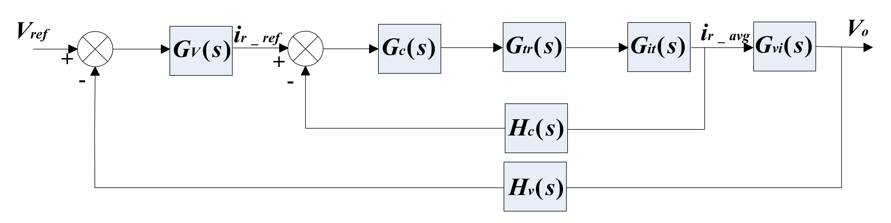
3.3. Design of Control Loop
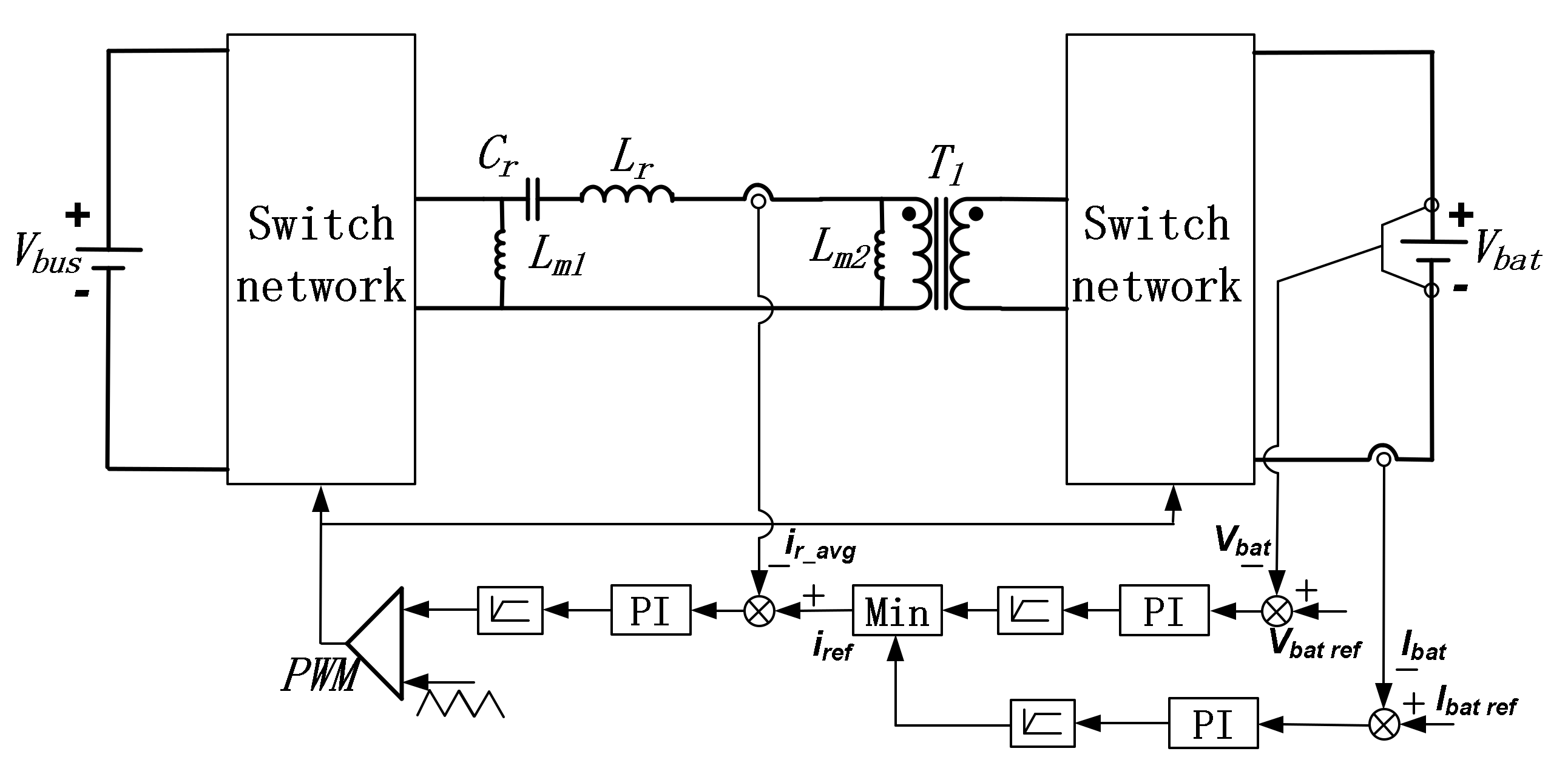
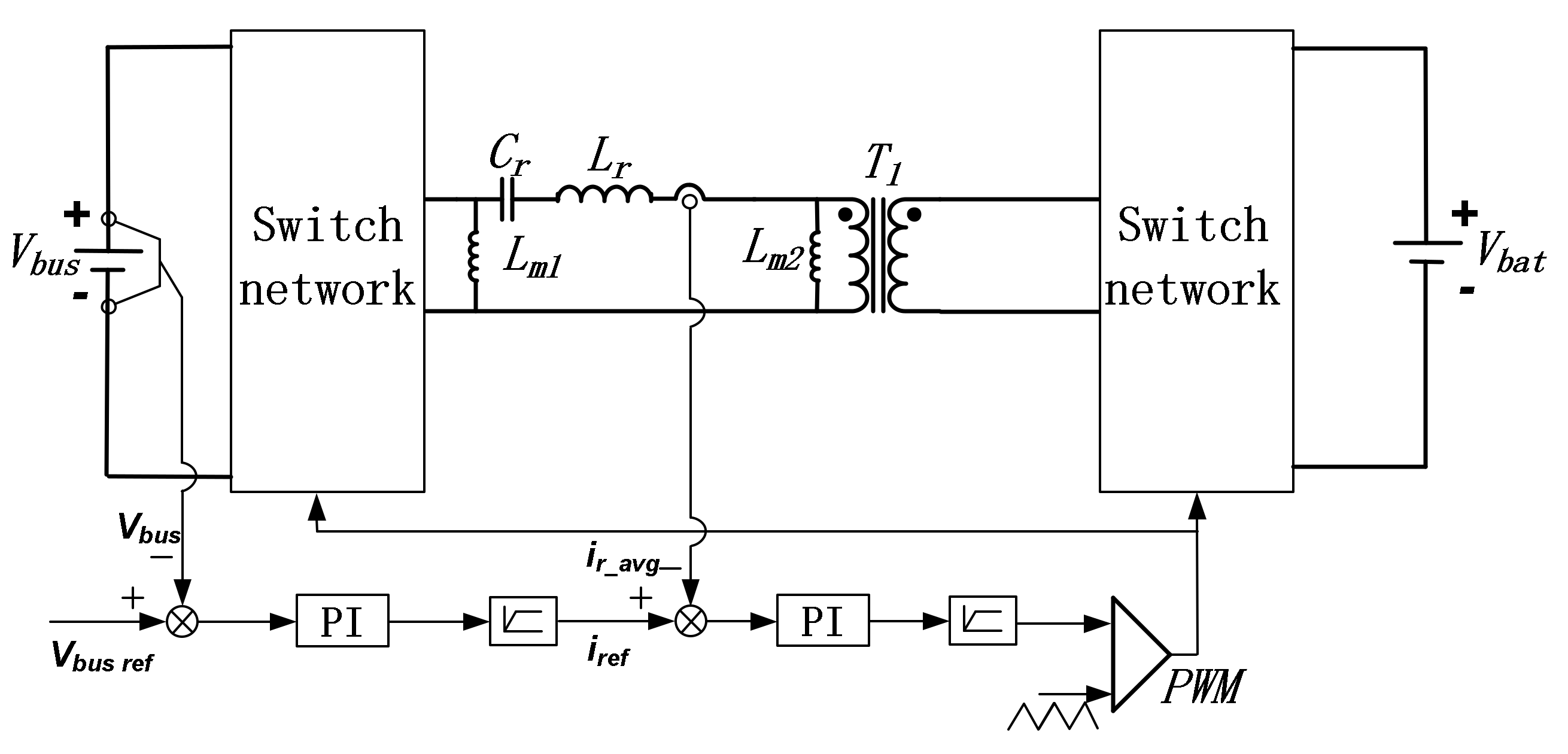
4. Control Strategy of Energy Storage System
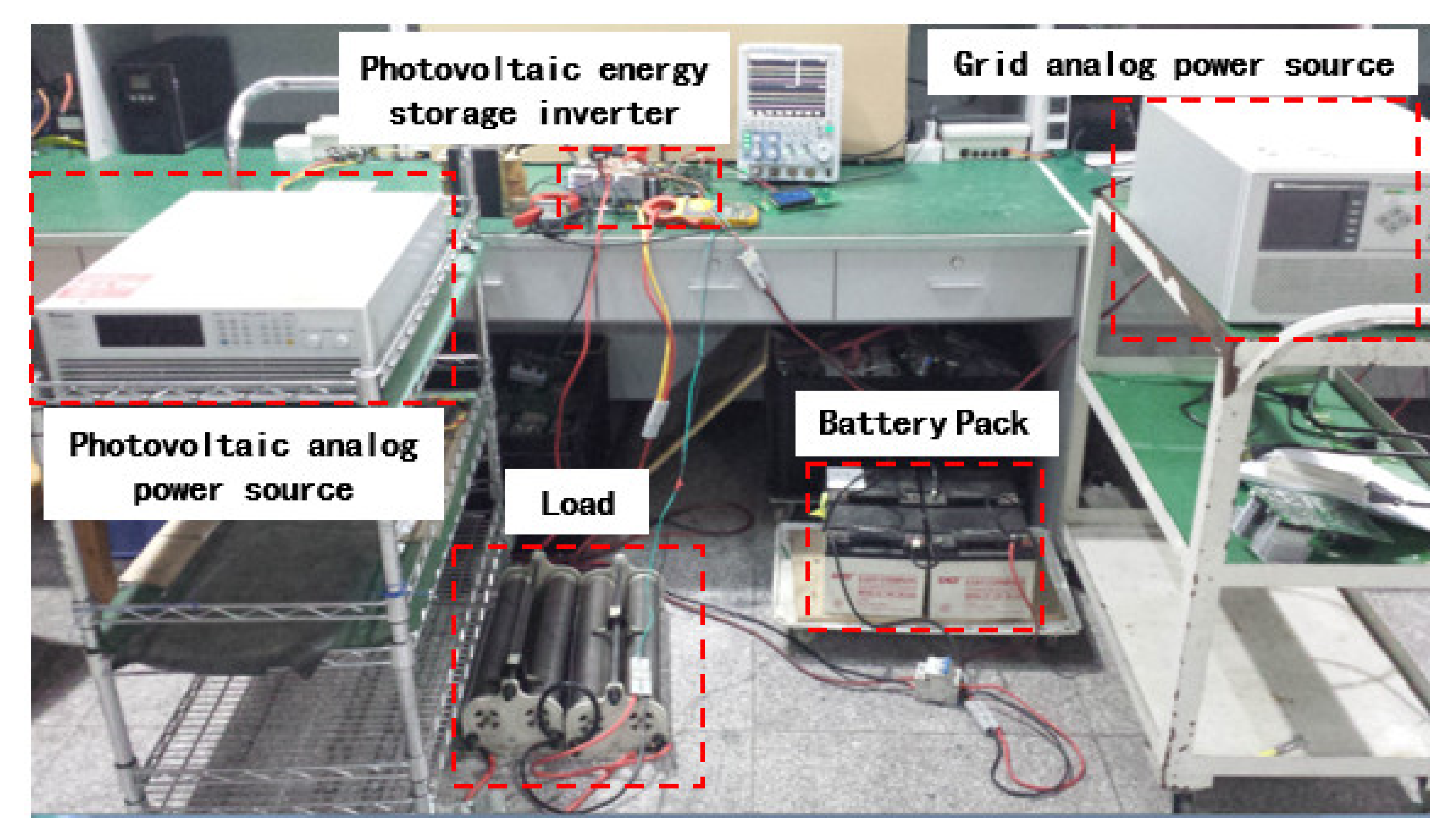
5. Experimental Results
6. Conclusions
- (1)
- Bidirectional symmetry of the converter can be achieved because of the addition of the compensating inductor. The converter has the advantage of simple control, and the soft-switching of the converter operating in both directions of power flow also can be achieved under the full-load range.
- (2)
- By analyzing the operation principle of the LLC bi-directional DC/DC converter, the gain of the bidirectional operation of the converter is derived. The converter can operate with the switching frequency between 50 kHz and 160 kHz, and the voltage gain range is around 1.3 to 0.8, correspondingly. Finally, the demand for a wide range of actual output voltage is met, and the margin is sufficient.
- (3)
- Compared with the system based on a conventional hard-switching DC/DC converter, there are more obvious advantages in the system based on a bidirectional LLC resonant converter. Improvement of efficiency of more than 3% for a bidirectional LLC resonant converter can be achieved in both directionals of power flow, which meets the high-efficiency requirements of the photovoltaic energy storage hybrid system.
Author Contributions
Funding
Institutional Review Board Statement
Informed Consent Statement
Conflicts of Interest
References
- Li, R.; Shi, F. Control and Optimization of Residential Photovoltaic Power Generation System with High Efficiency Isolated Bidirectional DC-DC Converter. IEEE Access 2019, 7, 116107–116122. [Google Scholar] [CrossRef]
- Gorji, S.A.; Sahebi, H.G.; Ektesabi, M.; Rad, A.B. Topologies and Control Schemes of Bidirectional DC-DC Power Converters: An Overview. IEEE Access 2019, 7, 117997–118019. [Google Scholar] [CrossRef]
- Inoue, S.; Ishigaki, M.; Takahashi, A.; Sugiyama, T. Design of an Isolated Bidirectional DC-DC Converter with Built-in Filters for High Power Density. IEEE Trans. Power Electron. 2021, 36, 739–750. [Google Scholar] [CrossRef]
- Zhang, N.; Sutanto, D.; Muttaqi, K.M. A four-port DC-DC converter to integrate energy storage system and solar PV to supply the grid and local load demand. In Proceedings of the Australasian Universities Power Engineering Conference (AUPEC), Wollongong, NSW, Australia, 27–30 September 2015; pp. 1–6. [Google Scholar] [CrossRef]
- Ning, J.; Zeng, J.; Du, X. A Four-Port Bidirectional DC-DC Converter for Renewable Energy-Battery-DC Microgrid System. In Proceedings of the IEEE Energy Conversion Congress and Exposition (ECCE), Baltimore, MD, USA, 29 September–3 October 2019; pp. 6722–6727. [Google Scholar] [CrossRef]
- Chen, C.; Zhao, X.; Yeh, C.; Lai, J. Analysis of the Zero-Voltage Switching Condition in LLC Series Resonant Converter with Secondary Parasitic Capacitors. In Proceedings of the IEEE Applied Power Electronics Conference and Exposition (APEC), Anaheim, CA, USA, 17–21 March 2019; pp. 828–832. [Google Scholar] [CrossRef]
- Zhou, J.; Ma, H. Full-Bridge LLC Resonant Converter with Parallel-Series Transformer Connection and Voltage Doubler Rectifier. In Proceedings of the 2019 10th International Conference on Power Electronics and ECCE Asia (ICPE 2019—ECCE Asia), Busan, Korea, 27–31 May 2019; pp. 1–6. [Google Scholar] [CrossRef]
- Wei, Y.; Mantooth, A. Topology Morphing Control Strategies for Full-bridge LLC Converter. In Proceedings of the 5th IEEE Workshop on the Electronic Grid (eGRID), Aachen, Germany, 2–4 November 2020; pp. 1–5. [Google Scholar] [CrossRef]
- Zhu, A.; Ma, Y.; Liu, Z.; Lu, H.; Zhang, F. Optimal Design of Control Strategy for Full-Bridge LLC Converter. In Proceedings of the IEEE Energy Conversion Congress and Exposition (ECCE), Detroit, MI, USA, 11–15 October 2020; pp. 2251–2257. [Google Scholar] [CrossRef]
- Lu, J.; Wang, Y.; Li, X.; Du, C. High-Conversion-Ratio Isolated Bidirectional DC-DC Converter for Distributed Energy Storage Systems. IEEE Trans. Power Electron. 2019, 34, 7256–7277. [Google Scholar] [CrossRef]
- Shi, L.; Liu, B.; Duan, S. Burst-Mode and Phase-Shift Hybrid Control Method of LLC Converters for Wide Output Range Applications. IEEE Trans. Ind. Electron. 2020, 67, 1013–1023. [Google Scholar] [CrossRef]
- Zhang, J.; Liu, J.; Yang, J.; Zhao, N.; Wang, Y.; Zheng, T.Q. An LLC-LC Type Bidirectional Control Strategy for an LLC Resonant Converter in Power Electronic Traction Transformer. IEEE Trans. Power Electron. 2018, 65, 8595–8604. [Google Scholar] [CrossRef]
- Kim, J.W.; Lee, M.; Lai, J.S. Efficient LLC resonant converter with a simple hold-up time compensation in voltage doubler rectifier. IEEE J. Emerg. Sel. Top. Power Electron. 2019, 7, 843–850. [Google Scholar] [CrossRef]
- He, P.; Mallik, A.; Cooke, G.; Khaligh, A. High-power-density high-efficiency LLC converter with an adjustable-leakage-inductance planar transformer for data centers. IET Power Electron. 2019, 12, 303–310. [Google Scholar] [CrossRef]
- Li, Y.; Shao, S.; Chen, H.; Zhang, J.; Sheng, K. High-gain high-efficiency IPOS LLC converter with coupled transformer and current sharing capability. CPSS Trans. Power Electron. Appl. 2020, 5, 63–73. [Google Scholar] [CrossRef]
- Wang, C.-S.; Zhang, S.-H.; Wang, Y.-F.; Chen, B.; Liu, J.-H. A 5-kW Isolated High Voltage Conversion Ratio Bidirectional CLTC Resonant DC-DC Converter with Wide Gain Range and High Efficiency. IEEE Trans. Power Electron. 2019, 34, 340–355. [Google Scholar] [CrossRef]
- Blinov, A.; Kosenko, R.; Chub, A.; Vinnikov, D. Bidirectional Soft Switching Current Source DC-DC Converter for Residential DC Microgrids. In Proceedings of the IECON 2018—44th Annual Conference of the IEEE Industrial Electronics Society, Washington, DC, USA, 21–23 October 2018; pp. 6059–6064. [Google Scholar] [CrossRef]
- Mukherjee, S.; Mukherjee, D.; Kastha, D. Multiport Soft-Switching Bidirectional DC-DC Converter for Hybrid Energy Storage Systems. In Proceedings of the IEEE Applied Power Electronics Conference and Exposition (APEC), Anaheim, CA, USA, 17–21 March 2019; pp. 2103–2109. [Google Scholar] [CrossRef]
- Jean-Pierre, G.; el Shafei, A.; Altin, N.; Nasiri, A. A Multiport Bidirectional LLC Resonant Converter for Grid-Tied Photovoltaic-Battery Hybrid System. In Proceedings of the 8th International Conference on Renewable Energy Research and Applications (ICRERA), Brasov, Romania, 3–6 November 2019; pp. 755–760. [Google Scholar] [CrossRef]
- Jean-Pierre, G.; Altin, N.; Nasiri, A. A Three-Port LLC Resonant Converter for Photovoltaic-Battery Hybrid System. In Proceedings of the IEEE Transportation Electrification Conference and Expo (ITEC), Detroit, MI, USA, 8 August 2019; pp. 1–6. [Google Scholar] [CrossRef]
- Parida, A.; Barai, M.; Mothukuri, K.R. Study of a soft switched Isolated DC-DC Bidirectional Converter for Electric Vehicles. In Proceedings of the TENCON 2019—2019 IEEE Region 10 Conference (TENCON), Kochi, India, 17–20 October 2019; pp. 1136–1141. [Google Scholar] [CrossRef]
- Vuchev, A.S.; Bankov, N.D.; Lichev, A.A. A control technique for a bidirectional series resonant DC-DC converter. In Proceedings of the XXVI International Scientific Conference Electronics (ET), Sozopol, Bulgaria, 13–15 September 2017; pp. 1–4. [Google Scholar] [CrossRef]
- Lichev, A.A.; Vuchev, A.S. Bidirectional Series Resonant DC-DC Converter Performance Improvement. In Proceedings of the XI National Conference with International Participation (ELECTRONICA), Sofia, Bulgaria, 23–24 July 2020; pp. 1–4. [Google Scholar] [CrossRef]
- Bhajana, V.V.S.K.; Drabek, P. A Novel ZCS/ZVS Bidirectional DC-DC Converter for Energy Storage Applications. In Proceedings of the International Conference on Applied Electronics (AE), Pilsen, Czech Republic, 10–11 September 2019; pp. 1–6. [Google Scholar] [CrossRef]
- Babu, B.; Divya, S. A Novel soft switching bidirectional dc dc converter. In Proceedings of the Second International Conference on Inventive Communication and Computational Technologies (ICICCT), Coimbatore, India, 20–21 April 2018; pp. 1752–1756. [Google Scholar] [CrossRef]
- Yanna, V.S.R.; Bhajana, V.V.S.K.; Drabek, P.; Popuri, M. A Novel Soft-Switching Bidirectional DC-DC Converter for Energy Storage Applications. In Proceedings of the International Conference on Applied Electronics (AE), Pilsen, Czech Republic, 8–9 September 2020; pp. 1–4. [Google Scholar] [CrossRef]
- Kim, E.; Oh, J.; Kim, M.; Lee, J.; Woo, J.; Jeon, Y. Enhancing Efficiency in Bidirectional Resonant DC-DC Converter. In Proceedings of the IEEE Applied Power Electronics Conference and Exposition (APEC), New Orleans, LA, USA, 15–19 March 2020; pp. 2230–2235. [Google Scholar] [CrossRef]
- Hsieh, Y.; Lee, F.C. Accurate Small-Signal Model for LLC Resonant Converters. In Proceedings of the IEEE Energy Conversion Congress and Exposition (ECCE), Baltimore, MD, USA, 29 September–3 October 2019; pp. 660–665. [Google Scholar] [CrossRef]
- Zong, S.; Luo, H.; Li, W.; He, X.; Xia, C. Theoretical Evaluation of Stability Improvement Brought by Resonant Current Loop for Paralleled LLC Converters. IEEE Trans. Ind. Electron. 2015, 62, 4170–4180. [Google Scholar] [CrossRef]
- Murakami, Y.; Sato, T.; Nishijima, K.; Nabeshima, T. Small signal analysis of LLC current resonant converters using equivalent source model. In Proceedings of the IECON 2016—42nd Annual Conference of the IEEE Industrial Electronics Society, Florence, Italy, 23–26 October 2016; pp. 1417–1422. [Google Scholar] [CrossRef]
- Cittanti, D.; Gregorio, M.; Armando, E.; Bojoi, R. Digital Multi-Loop Control of an LLC Resonant Converter for Electric Vehicle DC Fast Charging. In Proceedings of the IEEE Energy Conversion Congress and Exposition (ECCE), Detroit, MI, USA, 11–15 October 2020; pp. 4423–4430. [Google Scholar] [CrossRef]
- Huang, Y.; Hsieh, Y.; Lin, Y.; Chiu, H.; Lin, J. Study and Implementation on Start-Up Control of Full-Bridge LLC Resonant Converter. In Proceedings of the IEEE Transportation Electrification Conference and Expo, Asia-Pacific (ITEC Asia-Pacific), Bangkok, Thailand, 6–9 June 2018; pp. 1–5. [Google Scholar] [CrossRef]
- Hsieh, Y.-H.; Lee, F.C. Small-Signal Dynamic and High-Bandwidth Design of LLC Resonant Converters. In Proceedings of the IEEE Energy Conversion Congress and Exposition (ECCE), Detroit, MI, USA, 11–15 October 2020; pp. 6136–6143. [Google Scholar] [CrossRef]


| Parameters | Name | Value |
|---|---|---|
| battery parameters | capacity | 100 Ah |
| voltage ranges | 42 V to 57 V | |
| LLC parameters | T1 | 8.3:1 |
| Cr | 188 nF | |
| Lr | 20 μH | |
| Lm1 | 100 μH | |
| Lm2 | 100 μH | |
| Rated Power | 3 KW | |
| DC/AC parameters | DC bus voltage ranges | 350 V to 450 V. |
| Rate AC Voltage | 220 V | |
| Rated Power | 3 KW | |
| PV parameters | MPPT voltage ranges | 150 V~400 V |
| Rated Power | 5 KW | |
| Control parameters | Voltage loop Kp | 0.25 |
| Voltage loop Ki | 0.00015 | |
| Current loop Kp | 0.05 | |
| Current loop Ki | 0.0001 |
| Project | Power Direction | ||
|---|---|---|---|
| Lithium Batteries Get Power from the PV | Lithium Batteries Get Power from the Grid | Lithium Batteries Sends Power to the Grid | |
| Hard-Switch DC converter system efficiency | 93.5% | 92.6% | 92.3% |
| The bidirectional LLC resonant converter system efficiency | 96.9% | 96.1% | 95.6% |
Publisher’s Note: MDPI stays neutral with regard to jurisdictional claims in published maps and institutional affiliations. |
© 2022 by the authors. Licensee MDPI, Basel, Switzerland. This article is an open access article distributed under the terms and conditions of the Creative Commons Attribution (CC BY) license (https://creativecommons.org/licenses/by/4.0/).
Share and Cite
Xie, D.; Wang, L.; Zhang, Z.; Wang, S.; Kang, L.; Yao, J. Photovoltaic Energy Storage System Based on Bidirectional LLC Resonant Converter Control Technology. Energies 2022, 15, 6436. https://doi.org/10.3390/en15176436
Xie D, Wang L, Zhang Z, Wang S, Kang L, Yao J. Photovoltaic Energy Storage System Based on Bidirectional LLC Resonant Converter Control Technology. Energies. 2022; 15(17):6436. https://doi.org/10.3390/en15176436
Chicago/Turabian StyleXie, Di, Liangliang Wang, Zhi Zhang, Shoumo Wang, Longyun Kang, and Jigang Yao. 2022. "Photovoltaic Energy Storage System Based on Bidirectional LLC Resonant Converter Control Technology" Energies 15, no. 17: 6436. https://doi.org/10.3390/en15176436
APA StyleXie, D., Wang, L., Zhang, Z., Wang, S., Kang, L., & Yao, J. (2022). Photovoltaic Energy Storage System Based on Bidirectional LLC Resonant Converter Control Technology. Energies, 15(17), 6436. https://doi.org/10.3390/en15176436