Review

A Critical Analysis of the Oxy-Combustion Process: From Mathematical Models to Combustion Product Analysis

Department of Engineering for Innovation, University of Salento, SP per Monteroni, 73100 Lecce, Italy
*
Author to whom correspondence should be addressed.
Energies 2022, 15(18), 6514; https://doi.org/10.3390/en15186514
Submission received: 19 July 2022 / Revised: 22 August 2022 / Accepted: 2 September 2022 / Published: 6 September 2022
(This article belongs to the Topic Advances in Clean Energies)

Abstract

:
Fossil fuels are the most widely used resource for energy production. Carbon dioxide (CO2) emissions are correlated with climate change, and therefore these emissions must be reduced in the future. It is possible by means of many different technologies, and one of the most promising seems to be oxyfuel combustion. This process, with oxygen and recirculating gas, produces a concentrated stream of CO2 and water. In recent years, many scientists carried out research and studies on the oxyfuel process, but a sufficient level of knowledge was not yet reached to exploit the great potential of this new technology. Although such areas of research are still highly active, this work provides an overview and summary of the research undertaken, the state of development of the technology, and a comparison of different plants so far.

1. Introduction

From the industrial revolution to the first half of the 20th century, fossil fuels accounted for a significant fraction of global energy. Coal is regarded as the cheapest and most abundant resource, compared to all other fossil fuels, such as oil and natural gas [1,2]. During its fossilization process, it includes concentrations of hydrogen, oxygen, and other minerals, and its calorific value depends on their degree of concentration.
Coal is one of the main resources for the energy industry, and its increasing use worldwide led to problems of emissions of a significant amount of CO2 into the atmosphere, according to the general reaction:
C n H m + ( n   +   m 4   ) O 2   nCO 2 +   m / 2   H 2
CO2 is then released into the environment in a volume equal to the amount of carbon involved in the reaction. For energy-related CO2 emissions in 2021, 0.6 Gt of CO2 emissions from fuel combustion were produced from coal, 0.7 Gt of CO2 from oil, and 0.2 Gt of CO2 from gas [3].
Coal, as the most abundant, available, and affordable fuel, is the most reliable and easily accessible energy source, making a crucial contribution to world energy security [4,5] and constituting one of the fundamental pillars for the technological and social development of populous nations, such as China and India. Renewable energies are being developed, but to date, fossil fuels alone account for about 81% of energy consumption. However, this is not in line with the European Union’s 2030 target of reducing emissions by 55% compared to 1990 and the 2050 target of becoming the first climate-neutral continent. For these reasons, there must be a leap toward near-zero emission technologies.
There are different strategies for reducing CO2 emissions, such as the use of renewable energies with solar or wind energies that directly produce the electricity that can be used, geothermic energies capable of storing hot water under the earth’s surface into ducts to be reused for heating homes or reusing it in generators for the production of electricity or with the process of energy enhancement of solid urban waste and the production of biogas or with hydrogen that can be used to power vehicles or produce the high-temperature heat needed for industrial production processes. Other strategies can be the regulations on CO2 emissions [6], or utilizing CO2 as a raw material [7], but the growing focus on global warming stimulated the entire scientific community to work on reducing greenhouse gas emissions, particularly CO2 through carbon capture sequestration (CCS) [8]. These decarbonization processes do not decrease the CO2 formation of traditional systems, but rather capture carbon dioxide from atmospheric emissions of traditional combustion systems and transport it for permanent storage under the earth’s surface [9,10].
Many decarbonization systems are being studied and the most efficient and common ones are:
  • Post-combustion systems, which involve the separation of carbon dioxide by physical or chemical processes (for example adsorption in organic compounds or solid matrices with a 7–10% efficiency [11]). This process has the advantage of producing a carbon-free H2-based fuel, but it requires additional cost for syngas generation, and it is more expensive compared to other methods [12,13,14].
  • Pre-combustion processes, which provide the separation of CO2 from process gases before the combustion. At the end of the process, rich gases in carbon dioxide and water vapor are obtained. The vapor is removed from the recirculating gases and only CO2 is obtained, which is then compressed with an 8–12% efficiency [15]. This process generates minimum changes in the original configuration, but has a high NOx production and low CO2 purity in the flue gas [16,17].
  • Oxy-combustion is a technique of burning fuel using pure oxygen, resulting in higher temperatures, lower fuel use, and higher CO2 concentration. It is particularly promising, given the possibility of integrating this technology with other systems mentioned above. In fact, it increases the convective and radiative heat transfer, produces a highly concentrated CO2 stream, and a low NOx production [18] with a 7–11% of efficiency penalty [19].
  • Emerging technologies, such as membrane separation, chemical looping combustion, carbonation–calcination cycles, mineralization, etc. The use of these methods reduces energy consumption and consequently the energy penalty of carbon capture from power plants [20,21], but the emerging technologies were not demonstrated at sufficient scales for industrialization.
There are many differences between post- and oxy-combustion; one of the most significant differences is the higher cost of oxygen production, which usually is provided by cryogenic ASU, and there is an expected 3–4% energy penalty for this [22]. Another difference is that post-combustion produces high NOx and low CO2 purity in the fuel gas, while the second process produces low NOx and a highly concentrated CO2 stream. However, oxyfuel is considered an excellent technology that aims to improve the performance of combustion reactions while simultaneously reducing emissions of environmental pollutants [8]. Exhaust gas recirculation is a technique that is used for the benefit of certain characteristics of the oxyfuel process, such as temperature, burner aerodynamics, and residence times. At the end of the process, the exhaust gases are separated and compressed in such a way that only CO2 is ready to be stored.
It is estimated that the improvement of the efficiency of oxidation processes and the devolatilization of coal, through the achievement of the efficiency of coal-fired power plants of 40%, would lead to a saving of 2000 billion tons of CO2 per year [23].
There are not many pilot plants that use oxyfuel technology, but there are many studies carried out on the process, including experiments that provided insight into the design parameters and operational issues.
This review is focused on the science of oxyfuel combustion technology. It will discuss the fundamental study and the technological innovation of oxy-combustion by analyzing multiple aspects of the process, such as ignition, combustion characteristics, emissions, heat transfer, and oxygen separation methods.
The present paper is one of the few more comprehensive reviews now to be found in the literature because it analyzes the entire oxyfuel process, from the starting mathematical model to the pilot plants with a critical analysis of the reaction performance. It includes the historical development of oxyfuel combustion, shows the benefits of oxyfuel on pollutant emissions, and reports the opportunities, challenges, and future research recommendations about the oxy-combustion process. This review will be of great help to the entire scientific world in its comprehensive nature and detailed analysis of every aspect of the oxyfuel reaction.

2. Status of Oxy-Combustion

Oxyfuel technology was proposed for the first time in 1982 for producing a high pure CO2 stream for use in enhanced oil recovery [24]. In the 1990s, the topic of global warming and interest in implementing strategies to reduce CO2 levels resurfaced, and hence, technologies such as oxyfuel. Combustion in pure oxygen results in a high concentration of CO2 in the exhaust gases [25] that are composed of 80–85% of CO2 and water. Part of the gases will be recirculated into the reactor [5]; the presence of water allows combustion temperature to be lowered.
Studies show that oxy-combustion is the cheapest of the three CCS capture options. It is an environmentally friendly process that can still pollute due to other polluting emissions that the process may have. Simmonds et al. [26] examined the oxyfuel technologies and found that the use of oxyfuel resulted in 30% cost savings compared to other processes, such as post-combustion.
Oxy-combustion reaction is more efficient than the traditional combustion reaction. It allows for the obtaining of higher temperatures, a higher CO2 concentration downstream of the process, and lower fuel use; and in the case of using exhaust gas recirculation, it also offers more flexibility in design than traditional air-based systems.
The oxyfuel process has special characteristics that have beneficial effects on the efficiency of the reaction [27]:
  • the high-pressure operation causes the temperature condensation of water steam in the exhaust gas to be higher, resulting in more efficient latent heat recovery [28];
  • the energy required for CCS is reduced because CO2 is delivered at high pressure [29];
  • it is possible to decrease the size of the heat exchanger because the exhaust gases have a higher convective heat transfer coefficient [5].
In addition, oxy-combustion is preferable because, being controlled combustion that takes place between fuel and pure oxygen, it has fewer pollutants. In particular, at the end of the process, there will be a significant decrease in NOx and SOx, because the presence of nitrogen and sulfur, which are mostly in the air, decreases significantly with the participation of only oxygen in the reaction.
Many studies found NOx emission benefits in oxyfuel combustion, even at different CO2/H2O recirculation gas concentrations [4]. Many studies carried out on the oxyfuel process and its many applications. Normann et al. [30] investigated the synergy effects of an oxyfuel fired with carbon capture and co-firing of biomass. Their studies showed that with the oxyfuel process, it is possible to burn about 20% biomass and gain advantages for the synthesis of fuel for the transport sector.
CANMET organization worked on modeling the oxyfuel technology for a long time. The organization studied the effects of several factors on combustion performance [31,32]:
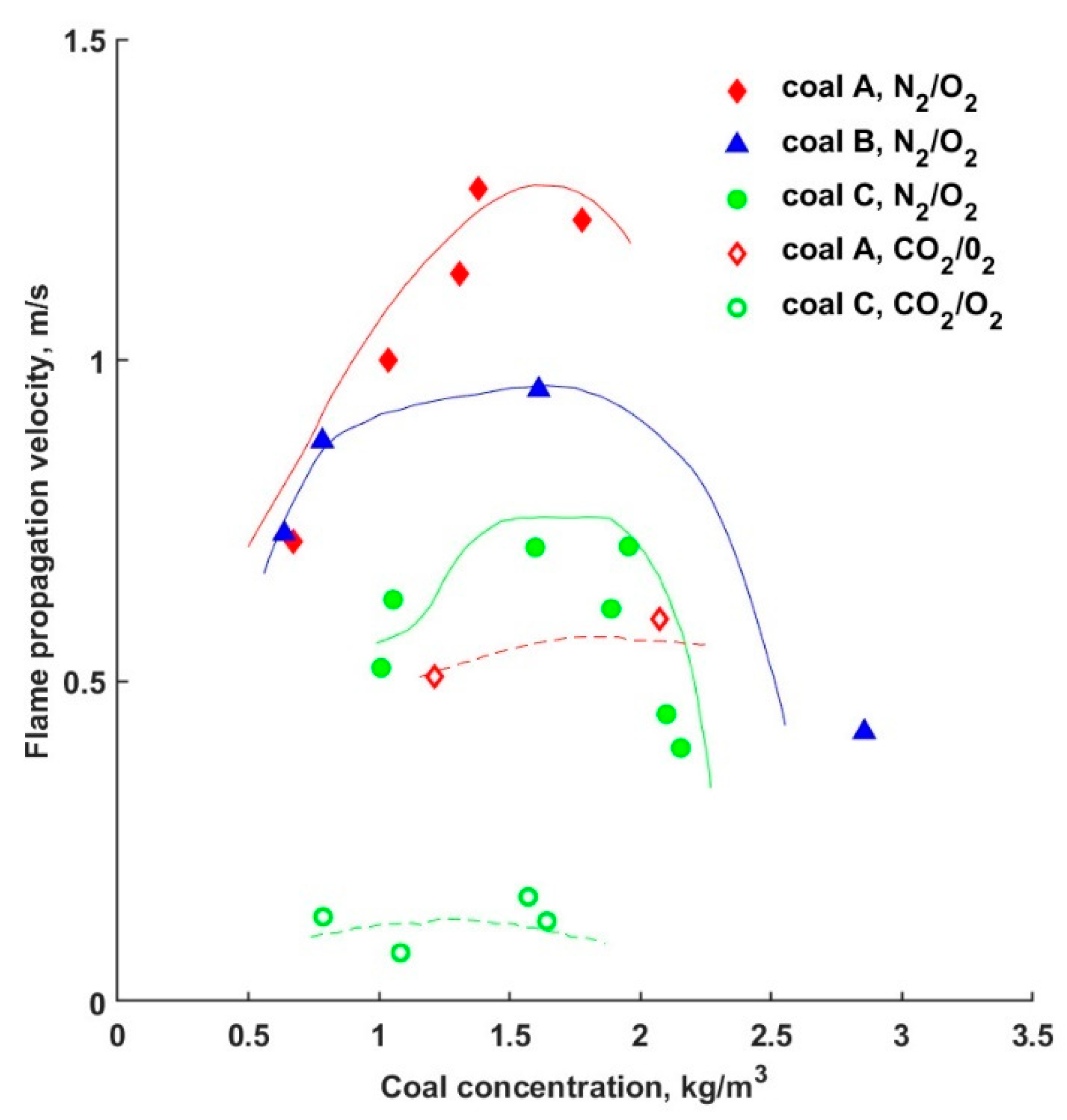
  • The concentration of oxygen increases in the process products, while the CO emission decreases. This phenomenon slows down the propagation of the flame in oxyfuel compared to air combustion;
  • the O2 purity has no significant effects on the flame temperature;
  • wet/dry recirculation;
  • burner performance.
Studies on the oxyfuel process show that combustion in oxygen is one of the main processes of producing CO2 that can be stored, with lower NOx emissions and higher thermal efficiency due to lower sensible heat losses from exhaust gases.

3. Mathematical Models

Several mathematical models try to reproduce the combustion process and theoretically estimate some quantities, such as the amount of CO2 and produced emissions, fuel used, or combustion temperatures.
In particular, kinetic mechanisms include:
  • A single-step scheme that used a single reaction to describe the oxidation of the fuel by the oxidant:
    C n H m + ( n + m 4 ) O 2 nCO 2 + m 2 H 2  
An example of a 1-step scheme for the combustion of methane with air is represented by the model formulated by Westbrook and Dryer (1981) [33], in which the reaction rate takes the form:
r = 2.12 10 11 exp ( 24358 T ) [ CH 4 ] 0.2 [ O 2 ] 1.3
  • A two-phase system using carbon dioxide as the medium reaction product. This mechanism is governed by the following two reactions:
    C n H m + ( n 2 + m 4 ) O 2 nCO + m 2 H 2 O  
    CO + 1 2 O 2 CO 2
Dryer and Glassman (1973) and Westbrook and Dryer (WD) (1984) [34] proposed the two most common mechanisms of this type. According to Westbrook and Dryer method, the kinetic equations of the reaction are, respectively:
r 1 = 10 9.45 exp ( 24358 T ) [ CH 4 ] 0.3 [ O 2 ] 1.3
r 2 = 10 12.35 exp ( 20132 T ) [ CO ] 1.0 [ O 2 ] 0.25 [ H 2 O ] 0.5
r 3 = 10 8.70 exp ( 20132 T ) [ CO 2 ] 1.0
This is a four-step method that accurately describes the different types of behavior involved in the combustion reaction. In 1988 Jones and Lindstedt (JL) [35] analyzed this type of mechanism. Their simplified scheme consists of the following molecular reactions:
C n H 2 n + 2 + n 2 O 2 nCO + ( n + 1 ) H 2
C n H 2 n + 2 + nH 2 O nCO + ( 2 n + 1 ) H 2  
CO + H 2 O CO 2 + H 2
H 2 + 1 2 O 2 H 2 O
The kinetics expressions for calculating reaction rates given by Jones and Lindstedt are useful for methane–air systems. These are:
r 1 = 4.4 10 11 exp ( 15105 T ) [ CH 4 ] 0.5 [ O 2 ] 1.25
r 2 = 3.02 10 8 exp ( 15105 T ) [ CH 4 ] 1.0 [ H 2 O ] 1.0
r 3 = 2.75 10 9 exp ( 10070 T ) [ CO ] 1.0 [ H 2 O ] 1.0
r 4 = 6.8 10 15   T 1 exp ( 20141 T ) [ H 2 ] 0.25   [ O 2 ] 1.50
When working under oxyfuel conditions, Andersen et al. [33,36] make modifications to the last two mechanisms mentioned above in order to improve the concentration profiles of the main species by modifying the reactions involving H2, CO, and CO2 [31,32]. Limiting the production of OH radicals results in lower water production and consequently decreases the amount of H2 in the oxy-combustion reaction.
The WD mechanism predicts the temperature profile, emission, CO levels in the combustor away from the flame, and post-combustion conditions compared to all other models.
In contrast, the JL method provides a lower amount of CO in the area in the center of the flame, in perfect agreement with what happens in the experiments.
When working under oxy-combustion conditions, it is possible to develop reduced kinetics capable of predicting the temperature profile and concentration, but with significant errors in estimating the flame speed.
However, the WD scheme provided a better prediction of peak CO concentrations and also a better temperature trend, which is also in agreement with experimental data. In general, a turbulence model of the eddy dissipation concept (EDC) should be preferred for modeling the oxyfuel process. Andersen et al. [36], however, said that the EDC model is not a model applicable to the combustion process in which the dissociation of the CO2 product can have such a significant and important effect.
Várhegyi et al. [37,38] studied the kinetics of the charcoal and observed that the amount of CO2 and temperature do not influence the kinetics of the reaction, probably because, at a lower temperature of about 400–900 °C, the reaction rate of the char-CO2 reaction is much lower than that of char-O2.

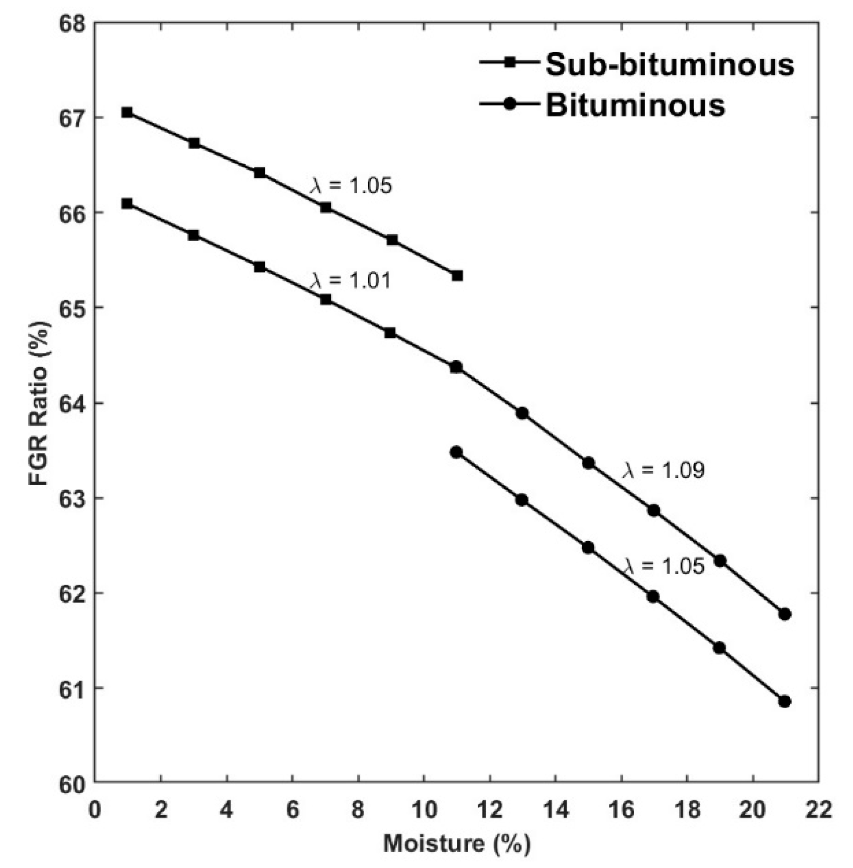
4. Recycles Ratio and Analysis of Flues Gas Recycled (FGR)

The FGR rate is the amount of recycled flue gas per mole of fuel, according to Equation (17):
FGR = Mole   of   recycled   flue   gas   stream total   mole   of   flues   gas   stream   of   boiler   outlet × 100
The most important parameter in the oxyfuel process is the percentage of recirculation gas. It is considered a fundamental tool for regulating combustion because it is used to dilute the combustion agent, varying the heat transfer properties, the reaction time, and influencing combustion efficiency. Lower recirculation ratios result in lower oxygen dilution and lower gas concentration inside the furnace. This leads to the possibility of using a smaller boiler and a more cost-effective process.
In general, the low recycled ratio permits raising the oxyfuel flame. This phenomenon allows for the use of a greater concentration of oxygen than the amount of air, in fact, about 35% of dry recycled exhaust gas is needed to match the flame temperature of air [25].
In 2010, Smart et al. [39] studied the effects of the recycled ratio on various parameters, such as adiabatic flame temperature, radiative heat flux, and the convective heat transfer coefficient. Their work showed the normalized calculated flame temperature and the peak normalized radiative heat flux, measured during an oxyfuel process as a function of the effective recycled ratio. In particular, convective heat flux increased with the increasing recycled ratio, and the peaks of radiative heat flux were inversely related to the recycled ratio.
Figure 1 shows a plot of the measured peak radiative heat flux and convective heat flux against a recycled ratio for the coal and normalized adiabatic flame temperature. It can be seen that there is no optimum recirculation ratio value for optimizing the radiative and convective components of the process at the same time. On the contrary, it can be seen that the radiative heat flux trend is inversely proportional to the FGR, while the convective heat flux has the same trend. The adiabatic flame temperature, which is very important, represented in the graph in red, has its optimum point with the convective heat flux at an effective recycle ratio of 74%.
Gas recirculation is an advantageous technique for the combustion process, but it can lead to corrosion phenomena at low and high temperatures, due to the presence of vapor and SO3 in the exhaust gases. To avoid this, all recirculation ducts should be kept above the outlet temperature.
Tan et al. [40] studied the combustion of coal in a mixture of pure O2 and recycled flue gas in a vertical combustor research facility to investigate the combustion characteristics of several different coals. They showed that by varying the amount of oxygen and gas recirculated in the combustion process, the latter could achieve the same performance as conventional combustion, but with lower emissions. They also studied the effects of moisture and oxygen from fuel (fuel-O) on FGR. The moisture can be considered as an inert diluting of O2.
Figure 2 illustrates the relationship between the FGR ratio (%) and the moisture degree of coal. It is possible to see that with the high moisture values, less recycled flue gas is required in the oxy-coal combustion compared to low moisture ones. In particular, coals with high fuel-O contents require less O2.
Toftegaard et al. [41] studied the oxyfuel combustion technology and retrofit implications, and in particular examined the advantages and disadvantages related to the concentration of oxygen and recirculated gases, in particular:
  • With oxygen addition before coal mills: but only if there is sufficient space in the recirculation duct to ensure proper mixing, otherwise the risk of combustion or explosion increases because primary flux may even cool down due to the low temperature of the incoming oxygen.
  • With oxygen addition after mills, but before the burners: it is possible to obtain the same oxygen concentration in the burners, but pure oxygen is likely to come into contact with the recirculated gases at high temperature.
  • Oxygen addition directly in burners: there is not an explosion in fuel gas ducts and the oxygen addition, and this would result in a better mixing of fuel and combustion agent in the area close to the near-burner zone.

5. Ignition and Flame Propagation

In combustion, replacing air with pure oxygen results in different temperature distributions and radiation fluxes within the combustion chamber, due to the different chemical properties of N2 and CO2. The difference in the flame shapes between the air-fired and oxyfuel-fired flame is due to the differences in the thermodynamic properties, because the triatomic molecule CO2 differs from nitrogen in several important physical and chemical properties.
Choi et al. [42,43] numerically investigated the structure of a CH4-O2 edge flame and compared it with the CH4-air edge and noted a clear distinction from the CH4-O2 counterpart.
The heat transfer in the oxyfuel process is different from conventional combustion, due to the different chemical composition of exhaust gases. The products of oxyfuel combustion are triatomic gases (CO2 and H2O), which are not as transparent to radiation as diatomic gases (N2). In addition, their partial pressure is very high, which increases the absorbance and emissivity of the exhaust gases.
Chen et al. [44] investigated the laminar flame and noted that in an O2/CO2 atmosphere, the adiabatic flame temperature and flame propagation speed are lower than values obtained in an air atmosphere. Furthermore, they noted that these values increase with increasing CO2; in particular, the temperature peak of the latter decreases by about 200 K [45].
Becher et al. [46] analyzed the emission spectra of substances produced by the dry and wet oxyfuel regimes. They concluded that the presence of water affects combustion temperature and flame stability. In fact, wet oxyfuel needs more oxygen, which in turn lowers the maximum flame temperature, but the measured radiation in the flue gases showed no large difference between both oxyfuels as, for example, the temperatures were similar.
CFD simulations of the oxy-combustion process showed that the flame was concentrated in the central region of the furnace and that under the same operating conditions oxy-combustion had a combustion delay due to the incomplete consumption of oxygen, as reported in the CFD simulation of a 100 kW unit firing propane [45,47]. As a consequence of this delay, there was a decrease in the peak flame temperature from 1518 K to 1853 K for the air-fired case.
Andersson et al. [48,49] studied and compared the intensity of the total radiation from oxyfuel flames by propane and lignite in Chalmers’ 100 kW test facility with air combustion. The experiment with 27% O2 produced a higher radiative heat transfer than air combustion, while the experiment with 21% O2/CO2 produced a lower flame temperature than the reference conditions for gas recirculation.
Riaza et al. [50] studied the ignition temperatures of high-volatile bituminous coal (BA) and semi anthracite coal (HVN), under different atmospheres. BA is a type of bituminous coal with 69% fixed carbon, 31% volatile matter, and 32.6 MJ/kg of heating value. HVN, instead, is a coal from the Hullera Vasco Leonesa in Leon, and it is composed of 90% anthracitic and 10% low volatile bituminous coal. They concluded that when the oxygen concentration increased (from 30% to 35%), the ignition temperature decreased to below that of the air conditions and the rates of devolatilization and oxidation of volatiles increased. On the other hand, a reduction in O2 retards the ignition of volatile chemical compounds and char [51].
Wall et al. [25,52,53] studied the formation of the flame in the furnace by a Fluent CFD model, including parameters such as oxygen distribution, temperature, velocity gas, and particle residence times. From the analysis of the results, they noted that the flame of the oxyfuel process was more elongated than the conventional air process and this caused a greater heat transfer to the back wall than air combustion.
Several factors depend on the flame conditions, including the reduction of NOx produced by the reaction. These depend on the recirculation of the gas, which is burnt again in contact with the hydrocarbons in the flame and the reducing atmosphere.
Bejarano and Levendis [54,55] studied the effects of oxygen concentration on burnout times. In general, for concentrations above 21%, the flame temperature influences the combustion time. In fact, if the oxygen concentration and combustion temperature increase at the same time, burnout times reduce. At 2100–2300 K with 50% of O2, the combustion duration decreases to 8–17 ms, and at 2300–2400 K with 100% of O2, the duration further decreases to 6–13 ms.
In 2005, Molina and Shaddix [56], with their experiments in a combustion reactor, suggested that the presence of CO2 retards coal and char ignition and influences the duration of devolatilization. This effect is caused by the increase in oxygen concentration because it accelerates particle ignition for both the N2 and CO2 atmosphere. They studied, also, the consequence of a higher oxygen concentration at different temperatures and observed that, in general, the 1650 K process has the same trend as the 1200 K process, but with a flame ignition delay and slight flame instability.
The effect of CO2 on flame propagation velocity was studied in 2007 by Suda et al. [57]. They noted that, since CO2 has a greater heat capacity ( ρ c p ) than air, the reaction temperature tends to decrease and so does, consequently, the reaction speed, according to the Arrhenius law.
Figure 3 shows a ten times higher flame speed in the air than in CO2 with 21% oxygen. This is caused by physical effects and the interaction of the reactants in the reaction, which are O, H, and CH radicals with CO2.
Tahir et al. [58] carried out a numerical study to analyze the characteristics of oxyfuel combustion inside a porous plate reactor by using commercial CFD software. In order to avoid hot spots in the reactor, it was decided to incorporate porous plates inside. Subsequently, the process was studied with different oxidant ratios and the adiabatic flame temperature was evaluated with the energy balance by the engineering equation solver (EES). The balance showed that the outlet temperature depended on the velocity field and the radiative effects occurring within the reactor, all of which depend on the concentration of the oxidant. In addition, it was found that for high oxidant flow rates and small reactors, the outlet temperature increases further.
It was concluded that to achieve similar combustion characteristics as that of air combustion, the oxidizer ratio of oxy-combustion needs to be changed, but so does the velocity field and the reactor dimensions.

6. Heat Transfer

Coal in contact with recycled exhaust reacts differently in terms of radiative and convective heat transfer than in interaction with N2.
In oxyfuel combustion with RFG, the concentration of CO2 and water in the combustion reaction is higher than under standard conditions, resulting in increased heat transfer in the convective section of the boiler.
During the combustion reaction, heat is released by radiation, conduction, and convection. In particular, particle radiation accounts for about 60–70% of the total energy, so radiative heat exchange is the fundamental heat transfer to be addressed when studying the development of the oxyfuel process [44].
Heat transfer varies with the concentration of H2O and CO2 because they are also good emitters and absorbers of thermal radiation [25,41,59].
O2, CO2, H2O, and CH4 participate in the oxy-combustion process, therefore, the emission of radiative heat transfer is necessarily different from air combustion.
Some studies show that the phenomenon of radiation intensifies as the flame temperature rises and the recirculation ratio of the combustion gases decreases. In 2009, Schiemann et al. [60] measured the coal particles’ temperature at three different residence times. They found the differences in heat capacity and heat conduction between the process that used carbon dioxide and the process that used nitrogen. Additionally, they found that the reaction speed increases with increasing oxygen concentration. In particular, the oxy-combustion with a 9% O2 concentration has a particle mean temperature that is higher than with a 3% O2 concentration, but both temperatures are smaller than air combustion, which is about 2000 K.
Andersson et al. [61] investigated thermal radiation in oxyfuel flames based on experiments, modeling, and using two different types of fuels: lignite and propane. In the simulations, propane flames were characterized as non-diffusing soot, while lignite flames were characterized as diffusing. Previous studies [62] show that the temperatures were slightly lower in the OF27 case compared to the air-fired case. Andersson explained that there was a significant increase in the radiation emitted by the oxyfuel flame, and this was due to the increase in CO2 concentration (around 90 vol % in oxyfuel compared to 15 vol % in air-firing).
The convection heat transfer coefficient is affected by flow velocity and gas characteristics. The convective heat transfer with combustible air is less than the oxygen fuel flow at the same rate as the value of the combustion air. This phenomenon is caused by the kinetic viscosity and the Reynolds number, and as a result, the convective heat transfer coefficient is higher. Carbon dioxide and steam have a higher thermal output compared to nitrogen, which leads to an increase in temperature through convection.
There are different opinions on heat transfer data, with many arguing that, in order to achieve an efficient result, the process should be optimized. Wall et al. [25] studied and tested three Australian pulverized coals, under oxy-dry fuel, oxy-wet fuel, and air combustion conditions. They calculated the mole fraction of oxygen required to maintain the same adiabatic flame temperature. Table 1 shows the thermal inputs used in their study.
In particular, the study showed that oxyfuel required more oxygen than air to maintain the theoretical AFT:
  • air combustion: 20% oxygen;
  • oxyfuel with wet recycle: 23.5–27% oxygen;
  • oxyfuel with dry recycle: 25–35%.
They also noted that, for all tests, oxyfuel exhaust had higher CO2 and H2O levels than air combustion, due to lower gas volumes and higher particulate concentrations. Thanks to their analysis it is understood that the heat transfer derives from the combustion products and the size of the particulate.
Smart et al. [39] studied the phenomena of heat transfer as well. In general, all phenomena depend on oxygen concentration, as confirmed by the studies of Black et al. [63]. There is no optimal amount of oxidant because heat transfer depends on many other factors, such as combustion properties.
In oxyfuel combustion, the emissivity can be significantly different within the boiler because the emissivity of the gases increases as the wavelength of the radiation increases. So, in oxy-combustion conditions, the adiabatic flame temperature decreases to maintain the same radiative and convective heat transfer flux, obtained with a higher recycle ratio, as shown by recent experimental studies conducted by Smart et al. [39,64].
Toporov et al. [65] studied the oxy-combustion heat transfer and noted that replacing N2 with CO2 increases the heat exchange as well as the density of the reaction mixture, but decreases its thermal diffusivity.

7. Oxygen Separation Methods

The efficiency of oxyfuel plants is affected by the consumption required for oxygen production and CO2 purification, so a key point for future development is to optimize these processes in order to decrease the consumption and increase process efficiency. The fundamental discriminator between traditional and oxyfuel combustion is the cost of oxygen. There are multiple methods to be used to have pure oxygen separation from the air stream. A summary of air separation technologies is given in Table 2 [66,67,68].
O2 is generally obtained from the cryogenic air separation unit, but this process requires compression of the air and then cooling to −183 °C in order to transform the oxygen into liquid and facilitate separation from nitrogen [69,70].
Trainer et al. [71] claim that cryogenics is currently the most cost-effective technique for producing large quantities of O2. However, there are other air separation techniques, such as pressure swing adsorption (PSA), vacuum swing adsorption (VSA), or polymeric membranes, which cannot compete economically for such quantities.
The membrane process exploits the difference in solubility and diffusivity of oxygen and nitrogen to separate the two components. It offers the best choice at a small scale, but oxygen obtained by polymer membranes has no sufficient purity (about 50 mol%). This process is limited to a single-stage process for economic considerations because the energy consumption of oxygen separation increases as a function of oxygen purity.
However, it is possible to use the waste heat in oxygen generation. In fact, power plants could be combined with adsorption-type oxygen separation processes (PTSA).
This type of process is preferred to produce large quantities of oxygen, around 300 tons per day. The PSA technology is widely used today, does not have high consumption, and allows 95% pure oxygen suitable for processes such as oxyfuel [67].
The power plant with the separation unit can be combined in three different ways:
  • the first method consists in using the energy produced by the power plant as input for the PSA system;
  • the second method is to use both electricity and waste heat from the power plants at a high temperature (about 90 °C) for the separation unit;
  • the third method involves using electricity and waste heat from the power plant at low temperatures (around 40 °C).
PTSA systems allow the utilization of waste heat and reduce the energy cost for oxygen production. Alternatively, membranes at high or medium temperatures can be used. The latter are polymeric membranes but have little stability and also produce small amounts of oxygen. For high temperatures, the use of ceramic membranes is the most common technique, because of their high thermochemical stability under harsh conditions [72].
For example, there are also ceramic-type membranes that have a higher separation efficiency than other technologies and are also able to recover compressed air after extracting oxygen.
The purity of the oxygen for combustion is one of the most important parameters to determine the air separation energy consumption because one of the most significant costs in any oxyfuel combustion scheme is the production of high-purity oxygen. Nakayama et al. [73] investigated the energy consumption of a large plant (1000 MWe) as a function of the purity of the input oxygen. Their studies confirmed that the optimum is obtained with 97% O2 because higher purities lead to high consumption for the oxygen separation process.
Although the combustion equipment is so tight against the entry of air, there is some ingress of inert in the burners and at the end of the process, so there will be a need to be a removal of all impurities from the final products. For this reason, Simmonds et al. [26] studied the optimum oxygen purity value, considering also the effect of the air inlet, which corresponds to 95%. This percentage corresponds to a good compromise between the costs of ASU to generate lower purity oxygen and the requirement to provide equipment to separate the inert from the CO2 stream.
To reduce the oxygen production cost in oxyfuel combustion, most scientists proposed a new technique based on chemical looping with oxygen uncoupling (CLOU). This method reduces the operating costs by 40–70%, compared to conventional oxygen production technologies [74]. It allows the combustion of solid fuels with CO2 separation. CLOU relies on the oxidation and reduction in metallic oxide as a means of separating oxygen from the air.
Cheng Zhou et al. [75] compared the oxygen produced by the cryogenic method and by the CLOU method, and carried out a techno-economic assessment of a hypothetical coalfired system. The results confirm that the oxidant reactor must have a higher temperature than the classic reactor and, for this reason, the CLOU method was integrated with natural gas firing or solar heating. This, however, is not always economically viable due to the high cost of fuel-fired power plants or solar plants. However, the results confirm that the oxy-combustion process using CLOU methods with CH4 integration can become economically viable.
Another oxygen production method is electrolysis, which is the most common method for hydrogen production. This process is an electrolytic decomposition of water into hydrogen and oxygen that takes place in electrolytic cells simultaneously separating hydrogen and oxygen. Although it has significant issues, due to the limited amount produced and the high costs, it requires the use of electricity to a decreasing extent as the temperature of the process increases. It is only cost-effective when there is a surplus of electricity.
During the electrolysis, the anodic reaction is the oxygen evolution reaction (OER), according to Equation (18):
2 H 2 O   ( l ) O 2 ( g ) + 4 H +   ( aq ) + 4   e  
2 H +   ( aq ) + 2   e   H 2   ( g )
In general, oxygen is produced at the anode under high-pressure conditions and leaves the system at ambient pressure. The high anode pressure of the electrolysis cell is an important disadvantage, but the energy content of the produced oxygen is higher than that of atmospheric oxygen and, if the high-pressure level of the oxygen is utilized subsequently in a chemical process, this disadvantage could be minimized [76].
For this reason, it is possible to suggest the use of the oxygen produced by electrolysis and not losing it in the environment; for example, using it in oxy-combustion.
The energy demand of alkaline electrolysis depends on the characteristics of the electrodes and operational conditions. The energy required for decomposing one mole of water into hydrogen and oxygen corresponds to the enthalpy of the formation of one mole of water. Smolinka et al. [77,78] studied atmospheric electrolysis and found that this process needs about 4.5 kWh/Nm3 H2 with 80% efficiency.

8. Emissions

Associated with oxyfuel, there are issues related to the mechanical and thermal resistance of the materials used. The difficulties that can be encountered could be the thermal resistance of the materials used in the construction of burners and furnaces; the difficulties in terms of safety, due to the use of pure oxygen, and the possible emission of pollutant species, mainly nitrogen oxides. The presence of nitrogen inside the chamber can be attributed almost entirely to outside air [72].
During the combustion process, the recirculation of exhaust gas takes place to control the flame temperature, to guarantee the minimum quantity of gas for heat transfer, and to compensate for the lack of nitrogen. Due to this recirculation, if not properly treated, corrosive and polluting species in the furnace in higher concentrations than in air combustion are generated [79]. Hou et al. [80] investigated the oxyfuel combustion characteristics of Australian coal in a 0.3 MWth system, and in particular, the influence of various oxygen flow rates and recirculated flue gas. They noted that the more the oxidant increases in the input, the more O2 is unreacted in the reaction, and in the output there is less CO2 as a flue gas [81].
Kumar et al. [82] compared the coal reactivity of four pulverized Australian coals in air and oxyfuel conditions and analyzed the reaction speed of the oxyfuel in the atmosphere. They noted that the speed decreases as the ash content increases at 1400 °C, but the ash increases as the concentration of oxygen in the reaction increases. Most of their studies confirmed a lower reactivity of the oxyfuel regime than air, because the difference in the reactivity between fuel and oxidizer depends on the properties of the reactants, their types, and the amount of O2 in the reaction.
The reactivity of coal increases with increasing oxygen in both combustions. Oxygen oxidation starts at 673 K and increases rapidly with increasing temperature until a maximum peak and then decreases due to the decreasing reactivity of coal, which is generally lower in oxyfuel combustion than in air combustion.
Vàrheyi et al. [37] studied the influence of carbon dioxide on reactivity. However, their studies did not lead to exact results, because experiments were concluded at 1073 K, i.e., before the start of gasification. At this temperature, the CO2 did not influence the reactivity of the coal in the process.
Pollutants such as NOx, SOx, and mercury have a different contribution under oxyfuel combustion because they are not released into the atmosphere, but are removed downstream by the combustion process with exhaust gas purification.

8.1. CO2, NOx and SOx Emissions

Tan et al. [40] conducted oxyfuel combustion research in a vertical combustor. This experiment was conceived specifically for combustion research in O2-enriched environments and mixtures of O2 and recycled flue gas, as well as to continuously monitor the flue gas compositions (O2, CO2, CO, NO, and NO2) and gas species concentrations. In order to do this study, they used a standard IFRF-type probe. The experiments were conducted with three different coals: eastern bituminous (EB), sub-bituminous (SB), and lignite (LN). Table 3 shows the measured flue gas composition (dry basis) for selected tests in both combustion processes: in air and in oxygen atmosphere.
Tan et al. [40] reported that for the LN-O2/RFG test, the values are not reliable, probably due to a non-tight boiler closure. From Table 3 it is possible to notice that, under O2/RFG conditions, the CO concentration in the flue gas was higher than in the air case, probably because of the slower diffusion rate of volatiles under high CO2 conditions.
Several researchers showed a reduction in NOx emission. Okazaki and Ando [83] studied the oxyfuel process with 21% O2 at 1450 K, analyzing the amount of NOx produced, the concentration of CO2 in the output, and the interaction between N2 and fuel, and they noted that the latter resulted in lower pollutants in the flame exit zone [84,85].
Hussein-Al Abbas et al. [86] studied three oxyfuel-fired conditions, namely OF25, OF27, and OF29 (respectively, 25 vol.%, 27 vol.%, and 29 vol.% O2 concentration). They observed a reduction in NOx in oxyfuel processes due to the lower temperature of combustion gases and the lack of the NO thermal mechanism. They also noticed an increase in the conversion rates of coal-N to NOx with a large amount of O2 in the input gas.
Hu et al. [87] studied the reduction in recycled NOx during oxyfuel combustion and noted that the reduction efficiency of recycled NO increased with an increasing fuel equivalent ratio and it varied from 10% to 80% with a fuel equivalence ratio from 0.5 to 1.4.
The oxy-combustion is a process with an excess of oxygen, and in their studies, Czakiert et al. [88,89] analyzed the effect of oxygen concentration, temperature, and pressure on carbon conversion and NOx, and SOx emissions. They reported that when the oxygen concentration was increased from 21% to 28%, NOx and SOx emissions were reduced.
In power plants, pollutants are removed downstream of the process by desulphurization units (FGD), but Beigzadeh et al. [90] explored how to do this between the compression and cooling phases of a CO2 capture unit and eliminated the need for FGD. They focused their attention on analyzing the front-end compression and cooling up to the dryer and continuously monitored emissions of O2, CO2, SO2, SO, NO, and NO2. The results indicate high removal efficiencies of SOx, over 90%, and of NOx, about 50%, using recirculated condensate or water in the inter-stage separators.
Andersson et al. [62] found that the oxyfuel combustion process, at high temperatures, produces less NO due to the absence of free N2 in oxyfuel combustion. It is an important factor in the overall reduction in NO and it enables the reverse of the Zeldovich mechanism. This thermal method consists of the production of NOx from N2 to O2:
N 2 + O   NO + N
N +   O 2 NO + ON
N + OH   NO + HN
In 2008, Normann et al. [91] examined the sensitivity of high-temperature NOx reduction to critical parameters and indicated that, at 1400 °C, the Zeldovich mechanism was not active and NOx reduction is related to the oxyfuel mechanism, while at low temperatures there is an increase in nitrogen concentration and produced thermal NOx.
Many researchers found that oxyfuel combustion can decrease SO2 emissions when compared to air combustion, because the high SO3 concentrations in the flue gas result in sulfur retention by ash or deposits in the furnace [80,85].
Under oxyfuel conditions with gas recirculation, high SO2 and SO3 concentrations could occur, which could cause serious problems for the CO2 capture and sequestration system (CCS) [85,92].
The presence of SOx depends on the amount of sulfur in the fuel. A high amount of SO3 is detrimental to oxyfuel because it corrodes the combustion chamber. In fact, its presence increases the acid dew point of the exhaust gases from 400 K to 430 K. Generally, during the combustion process, 1–5% of SO2 is converted to SO3, with a high CO2 concentration.
In 2009, a study by Santos [93] found that at 700–800 °C there is the maximum conversion of SO2 to SO3. Fleig et al. [94] suggested that the increase in SO3 is caused by three properties:
  • the oxidant has SO2 and increases during combustion;
  • the oxidant has oxygen, which decreases the flow in the chamber and increases SO3;
  • the replacement of N2 with CO2 increases the SO2/SO3.
During the oxy-combustion of Chinese Xuzhou bituminous coal, when replacing N2 with CO2, at 1000 K, sulfate in the CO2 atmosphere begins to decompose and forms carbonyl sulfide (COS) during the coal pyrolysis process. COS formation occurs according to the following equations:
H 2 S + CO COS +   H 2
H 2 S + CO 2 COS +   H 2 O
Gu et al. [95] studied the gas concentration distribution and the effects of oxygen concentration on emissions. Table 4 reports the emissions of CO and the mole of a fraction of CO2 and O2 for different inlet O2 concentrations. In general, the CO2 is lower than standard combustion, while O2 in the exhaust gas increases with the amount of oxidant input.
From data obtained by Gu’s studies [95], it can be seen that as the oxygen input concentration increases, CO emission decreases, probably because of the high rate of oxygen in the input that favored the production of CO from the char gasification and the oxidation of CO. However, this trend decreases in intensity as oxygen concentration rates above 30% are reached. This is due to the high temperature of the furnace. At low oxygen concentrations, the gasification rate was lower than the CO oxidation rate, which favored the formation of CO2. This theory is confirmed by the trend in the percentage of the mole fraction CO2 in the Table 4.

8.2. Ash

During the oxyfuel process, having a volume concentration of 30% oxygen in the gas causes the combustion temperature of the particles to increase. This phenomenon affects the vaporization of elements that serve as a bonding agent for ash deposits in the furnace [1]. However, ash deposition in the process depends on many factors, such as the aerodynamics of the particles in the boiler and their size, but also on the composition and partial pressure of CO2, SO2, and O2. To decrease particle deposition, the flame temperature and particle velocity could be reduced [96].
In 2006, Suriyawong et al. [97] studied the fly ash particle sizes and submicron particle formation under the oxyfuel combustion of sub-bituminous Powder River Basin coals. Their studies show that the substitution of N2 in the combustion process results in a decrease in the concentration of the particles. In particular, increasing the O2/CO2 ratio yields an increase in the particle size from 29 to 54 nm, an increase in volume fraction from 20% to 50%, and an increase in particle surface temperature from 1772 K to 2679 K.
Liu and Okazaki [98] and Kull et al. [99] studied the composition of the fly ash and found the sulfur enrichment of particles with a factor of 1.5–3, in comparison with the conventional air case for the higher SO2 partial pressure in the oxy case.

8.3. Corrosion

In oxy-combustion conditions, there are higher concentrations of corrosive gases, such as SO2, H2S, and HCl, and a significant partial pressure of CO2, which has a significant effect on the corrosion behavior in the furnace.
In 2008, Huenert et al. [100] studied the corrosion of steels with chromium contents in H2O/CO2 atmospheres (which corresponds to the atmosphere in oxyfuel combustion) at a temperature between 500 °C and 700 °C. They found that the corrosion mechanism changed at different temperatures, compared with the corrosion results in pure H2O, CO2, and O2, respectively. In particular, the oxide-scale thickness increased strongly with temperature and decreased with increased Cr content.
Recently, Covino Jr et al. [101] conducted corrosion exposure tests at high temperatures on three corrosion samples of the alloy and noted that at 675 °C, the corrosion rates were found to be high, especially in oxyfuel/RFG fire environment, compared to conventional combustion.
Stanger and Wall [102] found that the concentration of SO3 and H2O are decisive in determining the acid dew point of the flue gas, because at lower temperatures, the liquid H2SO4 condenses, causing corrosion problems, Therefore, in the oxyfuel mode, more SO3 production should be preferred in order to achieve a higher dew point. To decrease corrosion, the moisture content of the gases can be decreased by using a flue gas condenser (FGC), but this method has high investment and operation costs. Another cheaper practice is the injection of calcium-based and sodium-based SO2 sorbent in the furnace before the flue gas preheater [45].
Alternatively, in their work, Rathnam et al. [103] suggested desulphurization of the flue gas before recycling or oxyfuel combustion limited to low sulfur coals, in order to reduce the corrosion effect during the oxy-combustion process.

8.4. Mercury

The emissions of mercury from any coal-fired power plant is a primary environmental concern. If not removed sufficiently, the species of mercury could cause failure to any aluminum-based equipment.
Few studies considered mercury oxidation or its retention in fly ash. Farzan et al. [104,105] showed that the amount of mercury in flue gas is higher in the oxyfuel process than in the air combustion. This increase may be explained by increased chlorine concentration due to recycling and different radical concentration in the process. Zheng and Furimsky [106] said that the mercury emission would be unattested in an O2/CO2, and noted that the high concentration of SOx is believed to inhibit mercury capture.
Gharebaghi et al. [107,108] noted that the amount of mercury in the ashes depends on multiple factors, such as temperature, burnout, and particle size. They modeled the mechanism of mercury chlorination in flue gases under oxyfuel conditions and identified with their model that it is possible for the mercury transformation in an O2/CO2 environment with a temperature between 400 and 1800 K.
To reduce mercury emissions, Nuria Fernandez et al. [109] studied some regenerable substances based on gold nanoparticles in an activated carbon foam. In this way, the possibility of generating new toxic waste in energy production processes decreases. The designed process allows the mercury captured on the sorbent to be recovered after the sorbent is depleted, thus achieving 100% efficiency in capturing Hg0 in a CO2-enriched atmosphere with trace of HCl and SO2.

9. Industrial-Scale Pilot Project

The oxyfuel process has multiple developments. It is not only designed as one of the methods for capturing CO2, but has much potential.
There are not many pilot plants demonstrating the efficiency of an oxyfuel process and there is no substantial difference between a new oxyfuel plant and a plant that underwent oxyfuel retrofitting. There are simple pilot-scale projects, such as Schwarze Pumpe (Figure 4) or Callide (Figure 5).
In 2008, a 30 MW oxyfuel pilot plant was commissioned for the Schwarze Pumpe power plant in Germany [110]. The company Vattenfall developed this CCS technology. It was the first demonstration of the entire process chain including air separation treatment and CO2 purification. It concluded operations in April 2014 because the Swedish company stated that they want to invest in R&D projects that could contribute faster to the development of their business.
The plant’s Alstom-designed boiler fired primarily dried local lignite. O2 was provided by a cryogenic ASU. At the outlet, the gases were treated in the CPU capable of capturing 90% of CO2 and producing a maximum of 9 t/h of liquid CO2 at 99.7% purity.
Different configurations of the introduction of oxygen into the secondary recycle stream were analyzed, and the results show that if oxygen was introduced before the fuel stream arrived in the burner, the excess oxygen required for the process was limited to 3%, with a total oxygen content of 22%. On the other hand, if oxygen introduction into the combustor was controlled, it was possible to work with 2.5% excess oxygen and 18% total oxygen. The latter configuration allowed for working with less oxygen than the traditional combustion reaction [110].
The largest and most important oxyfuel plant is in Australia. It is in Callide and is a 30 MWe boiler. This is the first plant to generate electricity directly to the grid. As shown in Figure 5, the Callide process is composed of an ASU, where the separation of air between nitrogen and oxygen is achieved [111]. Oxygen is introduced into the combustor where the oxyfuel reaction takes place. The burner is equipped with a large ducting system for flue gas recycling. The flue gas purification system has fabric filters, and unlike the Australian power plants, has no FGD. The CPU can purify about 75 t/d of CO2 from the plant’s exhaust stream after recirculation, recovering about 12%, and the remaining amount is expelled into the stack.
Experimental results on this plant show that an oxyfuel combustion process with 27% oxygen has a heat balance in the boiler almost equivalent to that obtained with combustion in air. Other oxyfuel tests were also carried out involving the injection of the oxidant, the type of flue gas recirculation and the separation of water from the plant’s outflow [112,113].
The Australian Callide coal is relatively low in sulfur, and without recirculation of unburnt gases, high concentrations of SO2 in the boiler and ducts would occur in the plant. This effect, combined with the 18–25% of water, creates highly corrosive conditions for areas that are below the acid dew point [114].
An important development and application of CCS is the CO2 Technology Center Sulcis at Sotacarbo research center in Carbonia (Italy) [115]. The research center has five main projects and one of these consists in the pressurized oxy-combustion pilot plant of 50 MWth, in collaboration with ENEA and ITEA. The project involves the existing ISOTHERM pilot unit of ITEA, located in Gioia del Colle (Research and Development Center of Ansaldo Ricerche S.p.A) [116]. It is a 5 MWth plant used to carry out experiments on the flameless oxyfuel process at high temperatures and pressures.
In the ISOTHERM system, the coal is fed in slurry form to a pressurized combustor where it meets oxygen and recycled flue gases to obtain a uniformly high temperature of 1400–1700 °C at high pressure. In general, all fuel is converted into only CO2 and H2O to obtain more than 93% of CO2 concentration in flue combustion gases.
The oxyfuel process was also studied in fluidized bed reactors. There are two types of fluidized bed reactors: bubbling fluidized bed (BFB) and circulating fluidized bed (CFB). The first one is built to avoid solids elutriation from a bed into the convective passes and it has the fuel and oxidant distribution designed so that a high degree of internal circulation is obtained; the second method uses higher velocities to induce solids elutriation. The two methods are different characteristics, which are reported in Table 5.
Its efficiency depends on a number of factors, in particular, the conversion of coal and the degree of particle cleanliness, but there are no studies that report the last parameter because it depends on the fragmentation of the char particles.
Most of the studies were carried out in laboratory and pilot-scale conditions. The Centre of Research for Energy Resources and Consumption (CIRCE) [117] designed a 90 kWth BFB furnace and obtained 70 kWth as the thermal output with a mix of 65% CO2 and 35% O2. It was noted that increasing the temperature of the fluid bed improves sulfur retention capacity, and also, the temperature was demonstrated to influence NOx emission, because with high temperatures, an increase in fuel nitrogen conversion takes place.
Today, there is no fluidized bed technology demonstration plant. There is only the CIUDEN 30 MWth plant with a circulating fluidized bed boiler in northwestern Spain. On this plant, Lupion et al. [118] tested four fuels: anthracite, petroleum coke, subbituminous coal, and biomass. For all tests, the CO, NOx, and SOx emissions were low and nearly constant under oxy-combustion. These results will be used to scale up and design big plants with similar technologies.
Similarly, Zhong et al. [119] implemented CFD simulations of fluidized bed oxyfuel reactions. They compared the results with the data obtained from the 0.1 MWth pilot plant by Li et al. [120], and from the 12 MWth pilot plant by Amand et al. [121], and subsequently scaled the results to an industrial level with a 330 MWth plant.
In particular, Li et al. [120] used a variety of Chinese coals at different temperatures and excess O2 ratios. The aim of the tests was to investigate the effects of operation parameters on the results that are summarized in Table 6.
The results in Table 6 show that a higher combustion temperature can lead to lower N2O emission. This trend changed with the elevating of the overall oxygen concentration and excess oxygen ratio because higher excess oxygen leads to an increase in N2O.
Figure 6 shows the comparison of the flue gas composition between simulation and the experiment of the 0.1 MWth plant.
It can be found that the predicted concentration of CO2 and O2 showed good agreement with that of the experiment; the molar fraction of CO2 and O2 is very close in both cases. Figure 6b shows that the emissions of SO2 and CO were overestimated in the simulations, compared to the data obtained in the experiment.
Despite minor inconsistencies, the results obtained can be considered in line with those obtained in the realized model simulating the reaction. The model of Zhong et al. [119] was validated and they were able to scale-up the oxyfuel model to 330 MWth, in particular, they found that as the size of the plant increased, the fluidization state remained unchanged, the particle velocity became more turbulent, and the CO2 concentration increased as the height of the furnace increased.
Compared to the assumed emissions, the large-scale model showed lower pollutant emissions due to the increase in thermal input that favored the desulphurization efficiency in the oxyfuel CFB boilers, thus reducing the plant’s emissions.
Golachowska et al. [122] studied the pollutant emissions during oxyfuel combustion of biomass in a 12 kW bench-scale CFB combustor. In particular, three different coals were analyzed in the same CFB plant for their interaction with the oxidant and the pollutant emissions produced. At first, the different biomasses were dried according to the PN-EN ISO 18122. After that, they were carried out at a temperature of 850 °C in air and a mixture of O2/CO2 with O2 concentrations in a range from 21% to 40% vol. The major conclusions from this study are that during the oxy-combustion of biomass fuels, the optimal atmosphere is oxy-30 because the NO concentrations increase with increasing of O2 content in the O2/CO2. Moreover, higher concentrations of oxygen in the combustor enhance the combustion of volatile compounds and char, and lead to an increase in NO formation. Burning in oxy-30 or oxy-40 atmosphere causes an increase in SO2 and NO emissions, as well as a decrease in CO and N2O emissions.

10. Conclusions and Future Perspectives

This review provides a summary of the work done by various groups of researchers about oxyfuel combustion, which is an important CCS technology that drastically reduces CO2 emissions from power plants. It is similar to air-fired combustion technology, but the main differences occur in heat transfer, fuel reactivity, flame ignition, flame stability, and emissions.
The oxy-combustion process has many advantages and disadvantages. The main advantages are:
  • the possibility to retrofit an existing plant as either oxyfuel with CO2 liquefaction or flue gas liquefaction;
  • modify the technology of an existing process;
  • oxy-combustion is near-zero-emissions and it has low NOx emissions compared to conventional PF technology.
In general, using oxyfuel combustion requires more Capex (oxygen plant, flue gas recirculation system, etc.) and, according to many researchers, oxy-combustion produces less power than a traditional plant. A CO2 capture system requires storage locations, but not all locations are equipped with it. Nevertheless, many others consider the oxyfuel process to be one of the most promising combustion methods with low pollutant emissions.
Many studies confirmed that the oxy-combustion technology of pulverized coal is suitable for electric power plants intended for the capture of CO2, thus reducing the risks related to the choice of new technologies. Recently, many studies focused on the thermal optimization of all processes, and not to reduce the consumption of each one. The most common efficiency optimization strategies considered include the high-efficiency plant, O2 purity optimization, as well as preheating and optimizing flue gas recycling and desulphurization.
However, while the results on oxyfuel processes are encouraging, they refer to a limited type of coal. For this reason, a further experimental investigation is needed for a broad types of coals and also for other fuels.
There are still scientific and technological gaps regarding CO2 capture techniques in coal or gas-fired power plants. It is necessary a scientific effort to develop research projects to fill in the knowledge gaps in this area. For example, a new model suitable for gas radiation in oxyfuel combustion shall be developed, or a new design and arrangement for heat exchangers. In fact the oxy-combustion has a different flame development than that of the combustion reaction with air, therefore a simple modification of the traditional system is not enough.
Furthermore, there are still very few studies focusing on ash deposition, gas stratification to reduce the NOx, and emission of major elements during oxy-combustion of coal in fluidized combustors. In general, few models are developed to predict the performance of oxy fluidized bed combustors. In the future, the fluidized bed oxyfuel process could be analyzed in more details, including the study of all those parameters that are not yet examined and perhaps set up a few pilot plants to validate all the theoretical models.
Oxyfuel combustion could constitute an efficient technology for a first-generation coal CCS plant. Certainly, an important future development is to integrate oxyfuel technology with a “green” oxygen production technique. This is possible using water electrolysis, as reported earlier, and it has the potential to harness renewable electricity to produce hydrogen and convert it into chemical energy: so-called power-to-gas.

Funding

This research received no external funding.

Institutional Review Board Statement

Non applicable.

Informed Consent Statement

Non applicable.

Conflicts of Interest

The authors declare no conflict of interest.

Nomenclature

AFTadiabatic flame temperature
EDCeddy dissipation concept
EESengineering equation solver
CCScarbon capture sequestration
CFDcomputational fluid dynamic
CLOUchemical-looping with oxygen uncoupling
FGCflue gas condenser
FGDflue gas desulphurization
IFRFInternational Flames Research Foundation
ITMion transport membrane
OF25oxygen fraction 25%
OF27oxygen fraction 27%
OF29oxygen fraction 29%
PF purification technologies
PSApressure swing adsorption
PTSApressure temperature swing adsorption
RFGrecycled fuel gas
VSAvacuum swing adsorption

References

  1. Buhre, B.; Elliott, L.; Sheng, C.; Gupta, R.; Wall, T. Oxy-Fuel combustion technology for coal-Fired power generation. Prog. Energy Combust. Sci. 2005, 31, 283–307. [Google Scholar] [CrossRef]
  2. Wall, T.F. Combustion processes for carbon capture. Proc. Combust. Inst. 2007, 31, 31–47. [Google Scholar] [CrossRef]
  3. Available online: www.iea.org (accessed on 2 February 2022).
  4. Perrone, D. A study of oxy-Coal combustion with wet recycle using CFD modeling. In Energy Procedia, Proceedings of the ATI 2015-70th Conference of the ATI Engineering Association, Naples, Italy, 17–20 May 2015; Elsevier: Amsterdam, The Netherlands, 2015; Volume 82, pp. 900–907. [Google Scholar]
  5. Zheng, L. Oxy-Fuel Combustion for Power Generation and Carbon Dioxide (CO2) Capture; Elsevier: Sawston, Cambridge, 2011. [Google Scholar]
  6. Hashmi, R.; Alam, K. Dynamic relationship among environmental regulation, innovation, CO2 emissions, population, and economic growth in OECD countries: A panel investigation. J. Clean. Prod. 2019, 231, 1100–1109. [Google Scholar] [CrossRef]
  7. Baena-Moreno, F.M.; Rodríguez-Galán, M.; Vega, F.; Alonso-Fariñas, B.; Vilches Arenas, L.F.; Navarrete, B. Carbon capture and utilization technologies: A literature review and recent advances. Energy Sources Part A Recovery Util. Environ. Effects. 2019, 41, 1403–1433. [Google Scholar] [CrossRef]
  8. Koohestanian, E.; Shahraki, F. Review on principles, recent progress, and future challenges for oxy-Fuel combustion CO2 capture using compression and purification unit. J. Environ. Chem. Eng. 2021, 9, 105777. [Google Scholar] [CrossRef]
  9. Rolfe, A.; Huang, Y.; Haaf, M.; Pita, A.; Rezvani, S.; Dave, A.; Hewitt, N. Technical and environmental study of calcium carbonate looping versus oxy-Fuel options for low CO2 emission cement plants. Int. J. Greenh. Gas Control 2018, 75, 85–97. [Google Scholar] [CrossRef]
  10. Madejski, P.; Chmiel, K.; Subramanian, N.; Kuś, T. Methods and techniques for CO2 capture: Review of potential solutions and applications in modern energy technologies. Energies 2022, 15, 887. [Google Scholar] [CrossRef]
  11. Martelli, E.; Kreutz, T.; Carbo, M.; Consonni, S.; Jansen, D. Shell coal IGCCS with carbon capture: Conventional gas quench vs. innovative configurations. Appl. Energy 2011, 88, 3978–3989. [Google Scholar] [CrossRef]
  12. Spallina, V.; Gallucci, F.; Romano, M.C.; Annaland, M.V.S. Pre-Combustion packed bed chemical looping (PCCL) technology for efficient H2-Rich gas production processes. Chem. Eng. J. 2016, 294, 478–494. [Google Scholar] [CrossRef]
  13. Jansen, D.; Gazzani, M.; Manzolini, G.; van Dijk, E.; Carbo, M. Pre-Combustion CO2 capture. Int. J. Greenh. Gas Control. 2015, 40, 167–187. [Google Scholar] [CrossRef] [Green Version]
  14. Nemitallah, M.A.; Habib, M.A.; Badr, H.M.; Said, S.A.; Jamal, A.; Ben-Mansour, R.; Mokheimer, E.M.A.; Mezghani, K. Oxy-Fuel combustion technology: Current status, applications, and trends. Int. J. Energy Res. 2017, 41, 1670–1708. [Google Scholar] [CrossRef]
  15. Goto, K.; Yogo, K.; Higashii, T. A review of efficiency penalty in a coal-Fired power plant with post-Combustion CO2 capture. Appl. Energy 2013, 111, 710–720. [Google Scholar] [CrossRef]
  16. Canepa, R.; Wang, M. Techno-Economic analysis of a CO2 capture plant integrated with a commercial scale combined cycle gas turbine (CCGT) power plant. Appl. Therm. Eng. 2015, 74, 10–19. [Google Scholar] [CrossRef]
  17. Benhelal, E.; Zahedi, G.; Shamsaei, E.; Bahadori, A. Global strategies and potentials to curb CO2 emissions in cement industry. J. Clean. Prod. 2013, 51, 142–161. [Google Scholar] [CrossRef]
  18. Yang, X.; Clements, A.; Szuhánszki, J.; Huang, X.; Moguel, O.F.; Li, J.; Gibbins, J.; Liu, Z.; Zheng, C.; Ingham, D.; et al. Prediction of the radiative heat transfer in small and large scale oxy-Coal furnaces. Appl. Energy 2018, 211, 523–537. [Google Scholar] [CrossRef]
  19. Escudero, A.I.; Espatolero, S.; Romeo, L.M. Oxy-Combustion power plant integration in an oil refinery to reduce CO2 emissions. Int. J. Greenh. Gas Control 2015, 45, 118–129. [Google Scholar] [CrossRef]
  20. Figueroa, J.D.; Fout, T.; Plasynski, S.; McIlvried, H.; Srivastava, R.D. Advances in CO2 capture technology—The US Department of Energy’s Carbon Sequestration Program. Int. J. Greenh. Gas Control 2008, 2, 9–20. [Google Scholar] [CrossRef]
  21. Abu-Khader, M.M. Recent progress in CO2 capture/sequestration: A review. Energy Sources Part A 2006, 28, 1261–1279. [Google Scholar] [CrossRef]
  22. Rubin, E.S.; Mantripragada, H.; Marks, A.; Versteeg, P.; Kitchin, J. The outlook for improved carbon capture technology. Prog. Energy Combust. Sci. 2012, 38, 630–671. [Google Scholar] [CrossRef]
  23. IEA. International Energy Agency, Medium-Term Coal Market Report 2014; IEA: Paris, France, 2014; ISBN 978-92-64-22188-8. [Google Scholar]
  24. Horn, F.L.; Steinberg, M. Control of carbon dioxide emissions from a power plant (and use in enhanced oil recovery). Fuel 1982, 61, 415–422. [Google Scholar] [CrossRef]
  25. Wall, T.; Liu, Y.; Spero, C.; Elliott, L.; Khare, S.; Rathnam, R.; Zeenathal, F.; Moghtaderi, B.; Buhre, B.; Sheng, C.; et al. An overview on oxyfuel coal combustion—State of the art research and technology development. Chem. Eng. Res. Des. 2009, 87, 1003–1016. [Google Scholar] [CrossRef]
  26. Simmonds, M.; Miracca, I.; Gerdes, K. Oxyfuel technologies for CO2 capture: A techno-Economic overview. In Greenhouse Gas Control Technologies 7; Elsevier Science Ltd.: Amsterdam, The Netherlands, 2005; pp. 1125–1130. [Google Scholar]
  27. Dobó, Z.; Backman, M.; Whitty, K.J. Experimental study and demonstration of pilot-Scale oxy-Coal combustion at elevated temperatures and pressures. Appl. Energy 2019, 252, 113450. [Google Scholar] [CrossRef]
  28. Stanger, R.; Wall, T.; Spörl, R.; Paneru, M.; Grathwohl, S.; Weidmann, M.; Scheffknecht, G.; McDonald, D.; Myöhänen, K.; Ritvanen, J.; et al. Oxyfuel combustion for CO2 capture in power plants. Int. J. Greenh. Gas Control 2015, 40, 55–125. [Google Scholar] [CrossRef]
  29. Yin, C.; Yan, J. Oxy-Fuel combustion of pulverized fuels: Combustion fundamentals and modeling. Appl. Energy 2016, 162, 742–762. [Google Scholar] [CrossRef]
  30. Normann, F.; Thunman, H.; Johnsson, F. Process analysis of an oxygen lean oxy-Fuel power plant with co-Production of synthesis gas. Energy Convers. Manag. 2009, 50, 279–286. [Google Scholar] [CrossRef]
  31. Croiset, E.; Thambimuthu, K.V. Coal combustion with flue gas recirculation for CO2 recovery. In Proceedings of the 4th International Conference on Greenhouse Gas Control Technologies, Oxford, UK, 1 August 1999. [Google Scholar]
  32. Croiset, E.; Thambimuthu, K.; Palmer, A. Coal combustion in O2/CO2 mixtures compared with air. Can. J. Chem. Eng. 2000, 78, 402–407. [Google Scholar] [CrossRef]
  33. Westbrook, C.K.; Dryer, F.L. Simplified reaction mechanisms for the oxidation of hydrocarbon fuels in flames. Combust. Sci. Technol. 1981, 27, 31–43. [Google Scholar] [CrossRef]
  34. Westbrook, C.K.; Dryer, F.L. Chemical kinetic modeling of hydrocarbon combustion. Prog. Energy Combust. Sci. 1984, 10, 1–57. [Google Scholar] [CrossRef]
  35. Jones, W.; Lindstedt, R. Global reaction schemes for hydrocarbon combustion. Combust. Flame 1988, 73, 233–249. [Google Scholar] [CrossRef]
  36. Andersen, J.; Rasmussen, C.L.; Giselsson, T.; Glarborg, P. Global combustion mechanisms for use in CFD modeling under oxy-Fuel conditions. Energy Fuels 2009, 23, 1379–1389. [Google Scholar] [CrossRef]
  37. Várhegyi, G.; Szabó, P.; Jakab, E.; Till, F.; Richard, J.R. Mathematical modeling of char reactivity in Ar−O2 and CO2−O2 mixtures. Energy Fuels 1996, 10, 1208–1214. [Google Scholar] [CrossRef]
  38. Várhegyi, G.; Till, F. Comparison of temperature programmed char combustion in CO2-O2 and Ar-O2 mixtures at elevated pressure. Energy Fuels 1999, 13, 539–540. [Google Scholar] [CrossRef]
  39. Smart, J.; O’Nions, P.; Riley, G. Radiation and convective heat transfer, and burnout in oxy-Coal combustion. Fuel 2010, 89, 2468–2476. [Google Scholar] [CrossRef]
  40. Tan, Y.; Croiset, E.; Douglas, M.A.; Thambimuthu, K.V. Combustion characteristics of coal in a mixture of oxygen and recycled flue gas. Fuel 2006, 85, 507–512. [Google Scholar] [CrossRef]
  41. Toftegaard, M.B.; Brix, J.; Jensen, P.A.; Glarborg, P.; Jensen, A.D. Oxy-Fuel combustion of solid fuels. Prog. Energy Combust. Sci. 2010, 36, 581–625. [Google Scholar] [CrossRef]
  42. Choi, S.K.; Kim, J.S.; Chung, S.H. Structure of the edge flame in a methane–Oxygen mixing layer. Combust. Theory Model. 2009, 13, 39–56. [Google Scholar] [CrossRef]
  43. Yin, C.; Rosendahl, L.A.; Kær, S.K. Chemistry and radiation in oxy-Fuel combustion: A computational fluid dynamic modeling study. Fuel 2011, 90, 2519–2529. [Google Scholar] [CrossRef]
  44. Chen, L.; Yong, S.Z.; Ghoniem, A.F. Oxy-Fuel combustion of pulverized coal: Characterization, fundamentals, stabilization and CFD modeling. Prog. Energy Combust. Sci. 2012, 38, 156–214. [Google Scholar] [CrossRef]
  45. Zheng, C.; Liu, Z.; Xiang, J.; Zhang, L.; Zhang, S.; Luo, C.; Zhao, Y. Fundamental and technical challenges for a compatible design scheme of oxyfuel combustion technology. Engineering 2015, 1, 139–149. [Google Scholar] [CrossRef]
  46. Becher, V.; Bohn, J.P.; Dias, P.; Spliethoff, H. Validation of spectral gas radiation models under oxyfuel conditions—Part B: Natural gas flame experiments. Int. J. Greenh. Gas Control 2011, 5, S66–S75. [Google Scholar] [CrossRef]
  47. Al-Abbas, A.H.; Naser, J. CFD modelling of air-Fired and oxy-Fuel combustion in a 100 kW unit firing propane. In Proceedings of the International Conference on Mechanical Engineering 2011, Dhaka, Bangladesh, 18–20 December 2011. [Google Scholar]
  48. Andersson, K.; Johnsson, F. Flame and radiation characteristics of gas fired O2/CO2 combustion. Fuel 2007, 86, 656–668. [Google Scholar] [CrossRef]
  49. Hjärtstam, S.; Andersson, K.; Johnsson, F.; Leckner, B. Combustion characteristics of lignite-Fired oxy-Fuel flames. Fuel 2009, 88, 2216–2224. [Google Scholar] [CrossRef]
  50. Riaza, J.; Álvarez, L.; Gil, M.V.; Pevida, C.; Pis, J.J.; Rubiera, F. Effect of oxy-Fuel combustion with steam addition on coal ignition and burnout in an entrained flow reactor. Energy 2011, 36, 5314–5319. [Google Scholar] [CrossRef]
  51. Huang, X.; Jiang, X.; Han, X.; Wang, H. Combustion characteristics of fine-And micro-Pulverized coal in the mixture of O2/CO2. Energy Fuels 2008, 22, 3756–3762. [Google Scholar] [CrossRef]
  52. Khare, S. Heat Transfer in Pulverised air Furnaces Adapted to Oxyfuel. Master’s Thesis, Universiy of Newcastle, Newcastle, Australia, 2008. [Google Scholar]
  53. Khare, S.P.; Wall, T.F.; Farida, A.Z.; Liu, Y.; Moghtaderi, B.; Gupta, R.P. Factors influencing the ignition of flames from air-Fired swirl of burners retrofitted to oxy-Fuel. Fuel 2008, 87, 1042–1049. [Google Scholar] [CrossRef]
  54. Bejarano, P.A.; Levendis, Y.A. Combustion of coal chars in oxygen-Enriched atmospheres. Combust. Sci. Technol. 2007, 179, 1569–1587. [Google Scholar] [CrossRef]
  55. Levendis, Y.A.; Bejerano, P.A. Reaction times of burning bituminous chars at high O2 partial pressures. In Proceedings of the 31st International Technical Conference on Coal Utilization & Fuel Systems, Clearwater, FL, USA, 21–26 May 2006; Sakkestad, B.A., Ed.; Coal Technology Association: Gaithersburg, MD, USA, 2006; Volume I, pp. 145–157. [Google Scholar]
  56. Molina, A.; Shaddix, C.R. Effect of O2/CO2-Firing on Coal Particle Ignition; Sandia National Laboratories (SNL): Albuquerque, NM, USA; Livermore, CA, USA, 2005. [Google Scholar]
  57. Suda, T.; Masuko, K.; Sato, J.I.; Yamamoto, A.; Okazaki, K. Effect of carbon dioxide on flame propagation of pulverized coal clouds in CO2/O2 combustion. Fuel 2007, 86, 2008–2015. [Google Scholar] [CrossRef]
  58. Tahir, F.; Ali, H.; Baloch, A.A.; Jamil, Y. Performance Analysis of Air and Oxy-Fuel Laminar Combustion in a Porous Plate Reactor. Energies 2019, 12, 1706. [Google Scholar] [CrossRef]
  59. Kangwanpongpan, T.; Klatt, M.; Krautz, H.J. Challenges of oxyfuel combustion modeling for carbon capture. In EGU General Assembly Conference Abstracts; EGU General Assembly: Vienna, Austria, 2012; p. 9859. [Google Scholar]
  60. Schiemann, M.; Scherer, V.; Wirtz, S. Optical coal particle temperature measurement under oxy-Fuel conditions: Measurement methodology and initial results. Chem. Eng. Technol. Ind. Chem.-Plant Equip.-Process Eng.-Biotechnol. 2009, 32, 2000–2004. [Google Scholar] [CrossRef]
  61. Andersson, K.; Johansson, R.; Johnsson, F. Thermal radiation in oxy-Fuel flames. Int. J. Greenh. Gas Control 2011, 5, S58–S65. [Google Scholar] [CrossRef]
  62. Andersson, K.; Johansson, R.; Johnsson, F.; Leckner, B. Radiation intensity of propane-Fired oxy-Fuel flames: Implications for soot formation. Energy Fuels 2008, 22, 1535–1541. [Google Scholar] [CrossRef]
  63. Black, S.; Szuhánszki, J.; Pranzitelli, A.; Ma, L.; Stanger, P.J.; Ingham, D.B.; Pourkashanian, M. Effects of firing coal and biomass under oxy-Fuel conditions in a power plant boiler using CFD modelling. Fuel 2013, 113, 780–786. [Google Scholar] [CrossRef]
  64. Smart, J.P.; Patel, R.; Riley, G.S. Oxy-Fuel combustion of coal and biomass, the effect on radiative and convective heat transfer and burnout. Combust. Flame 2010, 157, 2230–2240. [Google Scholar] [CrossRef]
  65. Toporov, D.; Bocian, P.; Heil, P.; Kellermann, A.; Stadler, H.; Tschunko, S.; Foster, M.; Kneer, R. Detailed investigation of a pulverized fuel swirl flame in CO2/O2 atmosphere. Combust. Flame 2008, 155, 605–618. [Google Scholar] [CrossRef]
  66. Banaszkiewicz, T.; Chorowski, M.; Gizicki, W. Comparative analysis of oxygen production for oxy-Combustion application. In Energy Procedia, Proceedings of the 7th Trondheim CCS Conference, TCCS-7, Trondheim, Norway, 5–6 June 2013; Elsevier: Amsterdam, The Netherlands, 2014; Volume 51, pp. 127–134. [Google Scholar]
  67. Chorowski, M.; Gizicki, W.; Gromada, M. Aerobic Combustion for Dust and Fluidized Bed Combustion Integrated with CO2 Capture, Chapter 10: Oxygen Production for Aerobic Combustion; Nowak, W., Czakiert, T., Eds.; Wydawnictwo Politechniki Czstochowskiej: Czstochowa, Poland, 2012. [Google Scholar]
  68. Smith, A.R.; Klosek, J. A review of air separation technologies and their integration with energy conversion processes. Fuel Processing Technol. 2001, 70, 115–134. [Google Scholar] [CrossRef]
  69. Gellings, P.J. Handbook of Solid State Electrochemistry; CRC Press: Boca Raton, FL, USA, 1997. [Google Scholar]
  70. Sher, F.; Pans, M.A.; Sun, C.; Snape, C.; Liu, H. Oxy-Fuel combustion study of biomass fuels in a 20 kWth fluidized bed combustor. Fuel 2018, 215, 778–786. [Google Scholar] [CrossRef]
  71. Tranier, J.-P.; Dubettier, R.; Darde, A.; Perrin, N. Air separation, flue gas compression and purification units for oxy-Coal combustion systems. Energy Procedia 2011, 4, 966–971. [Google Scholar] [CrossRef]
  72. Castiglioni, R.; Croci, F. Fluid Dynamics Modelling of Natural Gas Oxyfuel Combustion. Master’s Thesis, Polytechnic of Milan, Milan, Italy, 2008. [Google Scholar]
  73. Nakayama, S.; Noguchi, Y.; Kiga, T.; Miyamae, S.; Maeda, U.; Kawai, M.; Ttanaka, T.; Koyata, K.; Makino, H. Pulverized coal combustion in O2/CO2 mixtures on a power plant for CO2 recovery. Energy Convers. Manag. 1992, 33, 379–386. [Google Scholar] [CrossRef]
  74. Wu, F.; Argyle, M.D.; Dellenback, P.A.; Fan, M. Progress in O2 separation for oxy-Fuel combustion—A promising way for cost-Effective CO2 capture: A review. Prog. Energy Combust. Sci. 2018, 67, 188–205. [Google Scholar] [CrossRef]
  75. Zhou, C.; Shah, K.; Song, H.; Zanganeh, J.; Doroodchi, E.; Moghtaderi, B. Integration options and economic analysis of an integrated chemical looping air separation process for oxy-Fuel combustion. Energy Fuels 2016, 30, 1741–1755. [Google Scholar] [CrossRef]
  76. Bensmann, B.; Hanke-Rauschenbach, R.; Arias, I.P.; Sundmacher, K. Energetic evaluation of high pressure PEM electrolyzer systems for intermediate storage of renewable energies. Electrochim. Acta 2013, 110, 570–580. [Google Scholar] [CrossRef]
  77. Bhandari, R.; Trudewind, C.A.; Zapp, P. Life cycle assessment of hydrogen production via electrolysis—A review. J. Clean. Prod. 2014, 85, 151–163. [Google Scholar] [CrossRef]
  78. Smolinka, T.; Günther, M.; Garche, J. Stand und Entwicklungs Potenzial der Wasserelektrolyse zur Herstellung vonWasserstoff aus Regenerativen Energien; Nationale Organisation Wasserstoff-Und Brennstoffzellen Technologie: Berlin, Germany, 2011. [Google Scholar]
  79. Habib, M.A.; Badr, H.M.; Ahmed, S.F.; Ben-Mansour, R.; Mezghani, K.; Imashuku, S.; la O’, G.J.; Shao-Horn, Y.; Mancini, N.D.; Mitsos, A.; et al. A review of recent developments in carbon capture utilizing oxy-Fuel combustion in conventional and ion transport membrane systems. Int. J. Energy Res. 2011, 35, 741–764. [Google Scholar] [CrossRef]
  80. Hou, S.S.; Chiang, C.Y.; Lin, T.H. Oxy-Fuel combustion characteristics of pulverized coal under O2/recirculated flue gas atmospheres. Appl. Sci. 2020, 10, 1362. [Google Scholar] [CrossRef]
  81. Liu, H.; Shao, Y. Predictions of the impurities in the CO2 stream of an oxy-Coal combustion plant. Appl. Energy 2010, 87, 3162–3170. [Google Scholar] [CrossRef]
  82. Kumar, R.R.; Elliott, L.; Moghtaderi, B.; Gupta, R.; Wall, T. Differences in Coal Reactivity in Air and Oxy-Fuel Conditions and Implications for Coal Burnout. The Clearwater Coal Conference: The 31st International Technical Conference on Coal Utilization and Fuel Systems. Coal Technol. Whats Next 2006, 1, 21–26. [Google Scholar]
  83. Okazaki, K.; Ando, T. NOx reduction mechanism in coal combustion with recycled CO2. Energy 1997, 22, 207–215. [Google Scholar] [CrossRef]
  84. Hu, Y.; Naito, S.; Kobayashi, N.; Hasatani, M. CO2, NOx and SO2 emissions from the combustion of coal with high oxygen concentration gases. Fuel 2000, 79, 1925–1932. [Google Scholar] [CrossRef]
  85. Croiset, E.; Thambimuthu, K.V. NOx and SO2 emissions from O2/CO2 recycle coal combustion. Fuel 2001, 80, 2117–2121. [Google Scholar] [CrossRef]
  86. Al-Abbas, A.H.; Naser, J.; Dodds, D.; Blicblau, A. Numerical modelling of oxy-Fuel combustion in a full-Scale tangentially-Fired pulverised coal boiler. Procedia Eng. 2013, 56, 375–380. [Google Scholar] [CrossRef]
  87. Hu, Y.Q.; Kobayashi, N.; Hasatani, M. The reduction of recycled-NOx in coal combustion with O2/recycled flue gas under low recycling ratio. Fuel 2001, 80, 1851–1855. [Google Scholar] [CrossRef]
  88. Czakiert, T.; Bis, Z.; Muskala, W.; Nowak, W. Fuel conversion from oxy-Fuel combustion in a circulating fluidized bed. Fuel Processing Technol. 2006, 87, 531–538. [Google Scholar] [CrossRef]
  89. Czakiert, T.; Sztekler, K.; Karski, S.; Markiewicz, D.; Nowak, W. Oxy-Fuel circulating fluidized bed combustion in a small pilot-Scale test rig. Fuel Processing Technol. 2010, 91, 1617–1623. [Google Scholar] [CrossRef]
  90. Beigzadeh, A.; Shafeen, A.; Abbassi, M.; Salvador, C.; Zanganeh, K.E. Optimized Multi-Pollutant Control in Oxy-Fuel Combustion Systems using CO2 Capture and Compression Process. Energy Procedia 2014, 63, 8134–8143. [Google Scholar] [CrossRef]
  91. Andersson, K.; Normann, F.; Johnsson, F.; Leckner, B. NO emission during oxy-Fuel combustion of lignite. Ind. Eng. Chem. Res. 2008, 47, 1835–1845. [Google Scholar] [CrossRef]
  92. Wang, F.; Shen, B.; Yang, J.; Singh, S. Review of mercury formation and capture from CO2-Enriched oxy-Fuel combustion flue gas. Energy Fuels 2017, 31, 1053–1064. [Google Scholar] [CrossRef]
  93. Santos, S. Fate of Sulphur in Coal during Oxyfuel Combustion with Recycled Flue Gas (Review of the Current State of uNDERSTANDING), IEC Gasification Conference Publication, IEA Greenhouse Gas R&D Programme. 2009. Available online: http://tu-freiberg.de/sites/default/files/media/professur-fuer-energieverfahrenstechnik-und-thermische-rueckstandsbehandlung-16460/publikationen/2009_ssantos-1.pdf (accessed on 24 February 2022).
  94. Fleig, D.; Normann, F.; Andersson, K.; Johnsson, F.; Leckner, B. The fate of sulphur during oxy-Fuel combustion of lignite. Energy Procedia 2009, 1, 383–390. [Google Scholar] [CrossRef]
  95. Gu, J.; Shao, Y.; Zhong, W. Study on oxy-Fuel combustion behaviors in a S-CO2 CFB by 3D CFD simulation. Chem. Eng. Sci. 2020, 211, 115262. [Google Scholar] [CrossRef]
  96. Scheffknecht, G.; Al-Makhadmeh, L.; Schnell, U.; Maier, J. Oxy-Fuel coal combustion—A review of the current state-of-The-Art. Int. J. Greenh. Gas Control 2011, 5, S16–S35. [Google Scholar] [CrossRef]
  97. Suriyawong, A.; Skeen, S.; Axelbaum, R.L.; Biswas, P. Experimental and modeling study on particle size distribution effects due to oxy-Combustion of coal. Environment and Sustainable Development. In Proceedings of the 23rd Annual International Pittsburgh Coal Conference, PCC-Coal-Energy, Pittsburgh, PA, USA, 25–28 September 2006. [Google Scholar]
  98. Liu, H.; Okazaki, K. Simultaneous easy CO2 recovery and drastic reduction of SOx and NOx in O2/CO2 coal combustion with heat recirculation. Fuel 2003, 82, 1427–1436. [Google Scholar] [CrossRef]
  99. Kull, R.; Maier, J.; Mönckert, P.; Scheffknecht, G.; Hjörnhede, A.; Anheden, M. 2008 Summary Report on Fly Ash, Deposit, Slagging and Corrosion under Oxyfuel Conditions in a 500 kW Test Rig. ENCAP Project. Available online: http://www.encapco2.or (accessed on 24 February 2022).
  100. Schulz, W.; Huenert, D.; Nitschke, H.; Saliwan-Neumann, R.; Kranzmann, A. Comparison of the corrosion behaviour of 9–12% Cr steels in H2O, H2O-CO2 and H2O-CO2-O2. In CORROSION 2009; OnePetro: Atlanta, Georgia, 2009. [Google Scholar]
  101. Covino, B.S.; Matthes, S.A.; Bullard, S.J. Effect of oxyfuel combustion on superheater corrosion. In Proceedings of the CORROSION 2008, New Orleans, LA, USA, 6–20 March 2008. [Google Scholar]
  102. Stanger, R.; Wall, T. Sulphur impacts during pulverised coal combustion in oxy-Fuel technology for carbon capture and storage. Prog. Energy Combust. Sci. 2011, 37, 69–88. [Google Scholar] [CrossRef]
  103. Rathnam, R.K.; Wall, T.; Moghtaderi, B. Reactivity of pulverized coals and their chars in oxyfuel (O2/CO2) and air (O2/N2) conditions. In Proceedings of the 3rd Oxyfuel Combustion Conference, Ponferrada, Spain, 9–13 September 2013. [Google Scholar]
  104. Edge, P.; Gharebaghi, M.; Irons, R.; Porter, R.; Porter, R.T.J.; Pourkashanian, M.; Smith, D.; Stephenson, P.; Williams, A. Combustion modelling opportunities and challenges for oxy-Coal carbon capture technology. Chem. Eng. Res. Des. 2011, 89, 1470–1493. [Google Scholar] [CrossRef]
  105. Mcdonald, D.K.; Farzan, H.; Varagani, R.; Docquier, N.; Perrin, N. Evaluation of Oxy-Coal Combustion at a 30 MWth Pilot. In Proceedings of the 1st International Oxyfuel Combustion Conference, Cottbus, Germany, 7–11 September 2009. [Google Scholar]
  106. Zheng, L.; Furimsky, E. Assessment of coal combustion in O2+ CO2 by equilibrium calculations. Fuel Processing Technol. 2003, 81, 23–34. [Google Scholar] [CrossRef]
  107. Gharebaghi, M.; Goh, B.; Jones, J.M.; Ma, L.; Pourkashanian, M.; Williams, A. Assessment of fate of mercury in oxy-Coal combustion. In Proceedings of the 1st Oxyfuel Combustion Conference, Cottbus, Germany, 7–11 September 2009; pp. 8–11. [Google Scholar]
  108. Gharebaghi, M.; Hughes, K.J.; Porter, R.T.J.; Pourkashanian, M.; Williams, A. Mercury speciation in air-Coal and oxy-Coal combustion: A modelling approach. Proc. Combust. Inst. 2011, 33, 1779–1786. [Google Scholar] [CrossRef]
  109. Fernández-Miranda, N.; Rodríguez, E.; Lopez-Anton, M.A.; García, R.; Martínez-Tarazona, M.R. Un nuovo approccio per trattenere il mercurio nei processi di generazione di energia: Assorbenti carboniosi rigenerabili. Energie 2017, 10, 1311. [Google Scholar] [CrossRef]
  110. Burchhardt, U.; Giering, R.; Weiß, G. Overview of Burner tests in Vattenfall’s Oxyfuel Pilot Plant. In Proceedings of the 3rd Oxyfuel Combustion Conference, Ponferrada, Spain, 10 September 2013. [Google Scholar]
  111. Spero, C. Oxyfuel project: Development status. In Proceedings of the 5th Oxyfuel Capacity Building Course, Ponferrada, Spain, 8–9 September 2013; Volume 15. [Google Scholar]
  112. Spero, C.; Yamada, T.; Nelson, P.; Morrison, T.; Bourhy-Weber, C. Callide oxyfuel project: Combustion and environmental performance. In Proceedings of the 3rd Oxyfuel Combustion Conference, Ponferrada, Spain, 9–13 September 2013; Volume 19. [Google Scholar]
  113. Spero, C.; Yamada, T.; Rees, G. Callide oxyfuel project: Overview of the commissioning experience. In Proceedings of the 3rd Oxyfuel Combustion Conference, Ponferrada, Spain, 10–12 September 2013. [Google Scholar]
  114. Uchida, T. Callide oxyfuel project: Boiler retrofit design. In Proceedings of the 2nd IEA Oxyfuel Combustion, Queensland, Australia, 12–16 September 2011. [Google Scholar]
  115. Sotacarbo. The CO2 technology Centre of Sulcis R&D program on carbon capture, utilization, and storage. In Proceedings of the CCUS Conference, Pittsburgh, PA, USA, 27 April–1 May 2015. [Google Scholar]
  116. Mills, S.J. Prospects for Coal, CCTs and CCS in the European Union; IEA Clean Coal Centre: London, UK, 2010. [Google Scholar]
  117. Mathekga, H.I.; Oboirien, B.O.; North, B.C. A review of oxy-Fuel combustion in fluidized bed reactors. Int. J. Energy Res. 2016, 40, 878–902. [Google Scholar] [CrossRef]
  118. Lupion, M.; Alvarez, I.; Otero, P.; Kuivalainen, R.; Lantto, J.; Hotta, A.; Hack, H. 30 MWth CIUDEN oxy-Cfb boiler-First experiences. Energ. Procedia 2013, 37, 6179–6188. [Google Scholar] [CrossRef]
  119. Gu, J.; Liu, Q.; Zhong, W.; Yu, A. Study on scale-Up characteristics of oxy-Fuel combustion in circulating fluidized bed boiler by 3D CFD simulation. Adv. Powder Technol. 2020, 31, 2136–2151. [Google Scholar] [CrossRef]
  120. Li, S.; Xu, M.; Jia, L.; Tan, L.; Lu, Q. Influence of operating parameters on N2O emission in O2/CO2 combustion with high oxygen concentration in circulating fluidized bed. Appl. Energy 2016, 173, 197–209. [Google Scholar] [CrossRef]
  121. Aamand, L.E.; Leckner, B.; Andersson, S. Formation of nitrous oxide in circulating fluidized-Bed boilers. Energy Fuels 1991, 5, 815–823. [Google Scholar] [CrossRef]
  122. Kosowska-Golachowska, M.; Luckos, A.; Kijo-Kleczkowska, A. Emissioni inquinanti durante la combustione Oxy-Fuel della biomassa in un combustore CFB su scala da banco. Energie 2022, 15, 706. [Google Scholar] [CrossRef]
Figure 1. The effect of recycle ratio on various parameters characterizing the oxyfuel process. Adapted with permission from Ref. [39] Copyright © 2010 Elsevier Ltd.
Energies 15 06514 g001
Figure 2. Effect of moisture in coal on fuel gas recycle ratio.
Energies 15 06514 g002
Figure 3. Flame propagation velocity in air and the simulated oxyfuel atmosphere for three different types of coal (A, B, C). Adapted with permission from Ref. [57] Copyright © 2006 Elsevier Ltd.
Energies 15 06514 g003
Figure 4. Schematic of the Schwarze Pumpe pilot plant [110].
Energies 15 06514 g004
Figure 5. The Callide oxyfuel pilot process [111].
Energies 15 06514 g005
Figure 6. Comparison between simulation and experiment from the 0.1 MWth plant: (a) molar fraction of CO2 and O2 [%]; (b) SO2 and CO emission [mg/MJ].
Energies 15 06514 g006
Table 1. Thermal inputs used in the study of Wall et al. Adapted with permission from Ref. [25] Copyright © 2009 The Institution of Chemical Engineers.
Coal ACoal BCoal C
AirOxyAirOxyAirOxy
Estimated furnace heat transfer (kW)348354368373342347
Estimated heat flux (kW/m2)12.612.813.313.512.312.5
% Difference, change from air to oxy+1.6%+1.5%+1.6%///
Water inlet temperature [°C]37.838.132.834.2-NA-NA
Water exit temperature [°C]47.549.140.944.0-NA-NA
Estimated furnace heat absorption [kW]354392336356-NA-NA
Table 2. Separation technologies of O2.
TechnologyO2 Purity %Capacity
(Tons Per Day)
QualityDriving ForceStart-Up Time
Cryogenic
Matured
99+Up to 4000N, Ar, Kr, Xe;
Very good
ElectricityHours/days
Adsorption95+Up to 300N, Bad, ca.11%Electricity (70–90 °C)Minutes/hours
Membrane
(Polymer)
50up to 20N ElectricityMinutes
Membrane (ITM)99+Laboratory scaleNElectricity
(800 °C)
Hours
Table 3. Exhaust gas compositions used for testing.
Test IDO2 (%)CO2 (%)CO (ppm)SO2 (ppm)NO (ppm)NO (ng/J)
EB-air2.01751615583211
EB-O2/RFG2.1978514311332233
SB-air2.0179175707236
SB-O2/RFG2.298753721183148
LN-air3.3171277771269
LN-O2/RFG2.7921478555568
Table 4. Emissions of CO and mole fraction of CO2 and O2 for different inlet O2 concentrations.
O2 in Inlet (%)Emission of CO (mg/MJ)Mole Fraction of CO2 (%)Mole Fraction of O2 (%)
2147595.83.9
2525095.14.6
3011094.55.25
357593.36.25
Table 5. Characteristics of bubbling fluidized bed (BFB) and circulating fluidized bed (CFB).
Design ParameterBFBCFB
Combustion temperature [°C]700–900800–900
Fluidization velocities [m/s]1–33–10
Fuel particle size [mm]0–30–0.3
Combustion efficiency [%]90–9695–99.5
Table 6. Experimental condition and results in the tests by Li [42].
TestTemperature [°C]Excess O2 RatioNO [mg/MJ]N2O [mg/MJ]SO2
[mg/MJ]
CO
[mg/MJ]
O2 [%]
18001.1840.292.5183.4104.87.2
28501.1842.876.5194.158.37.5
39001.1848.239.619827.57.6
48501.1837.1125.0259.784.95.4
58501.1838.2105.1196.273.86.2
68501.1850.882.6161.370.66.9
78501.0627.242.3244.6483.03.2
88501.1133.956.6240.1334.35
98501.1539.676.6241.3189.86.2
108501.1852.772.2133.668.87.6
118501.1851.574.4170.464.87.3
128501.1837.881.3207.375.27.2
138501.1839.078.7201.569.17.5
148501.1841.279.8196.261.67.4
Publisher’s Note: MDPI stays neutral with regard to jurisdictional claims in published maps and institutional affiliations.

