Review

A Review of the Mitigating Methods against the Energy Conversion Decrease in Solar Panels

by
Gabriella-Stefánia Szabó
1,*,
Róbert Szabó
2 and
Loránd Szabó
3,*
1
Department of Chemistry and Chemical Engineering of Hungarian Line, Babeș-Bolyai University, 400028 Cluj-Napoca, Romania
2
Department of Environmental and Plant Protection, University of Agricultural Sciences and Veterinary Medicine, 400372 Cluj-Napoca, Romania
3
Department of Electrical Machines and Drives, Technical University of Cluj-Napoca, 400114 Cluj-Napoca, Romania
*
Authors to whom correspondence should be addressed.
Energies 2022, 15(18), 6558; https://doi.org/10.3390/en15186558
Submission received: 25 July 2022 / Revised: 3 September 2022 / Accepted: 6 September 2022 / Published: 8 September 2022
(This article belongs to the Topic Advances in Clean Energies)

Abstract

:
Using solar panels is one of the cleanest ways to generate electricity ever created by mankind. The efficiency of rapidly expanding solar panels decreases during their lifetime for several reasons, such as photodegradation, hot spots, potentially induced degradation, etc. Dirt and debris accumulation on the surface of the solar panels can also significantly contribute to their performance degradation due to the diminishing of the solar radiation reaching their active surfaces. Numerous degradation mitigation methods are cited in the literature. This article briefly outlines these basic measures.

1. Introduction

The energy received on Earth from the Sun is plentiful and totally renewable. Therefore, its use has attracted the interest of mankind since ancient times [1,2]. Nowadays, the direct conversion of solar energy into electricity seems to be one of the most feasible future solutions for the increased energy demands and environmental protection.
Consequently, in the last decade, the greatest power generation increase was due to the installation of solar panels [3]. In 2020, the worldwide total solar energy conversion capacity reached 773.2 GW, and it is expected to be doubled at least until 2025 [4].
Current technological developments are twofold. First, significant efforts are made for the improvement of the efficiency of the solar cells themselves. Secondly, the sun tracking systems are perfected to correctly place the solar cells in that position where the energy conversion is at its maximum.
While the rated efficiency of the newly fabricated solar panels continues to increase, the amount of electrical energy these panels can convert decreases over time. Even the highest quality solar panels degrade at a rate of about 0.5% per year, resulting in a 12–15% loss of efficiency over their expected life of 25–30 years. Deterioration of solar panels is primarily due to normal wear and tear over time from exposure to UV rays and harsh weather conditions. Various mechanical and chemical degradations have been mentioned in the literature, such as light-induced and age-related degradation, potential induced degradation, etc. In addition to all these negative effects, solar panels are also polluted by sand, dust, and other particulate matter (from agricultural and construction works as well as air pollution), leaves, bird droppings, etc. These unavoidable deposits cause the greatest loss to the energy conversion efficiency of solar panels.
There are several ways to limit all these negative effects that affect solar panel performance. A large part of the degradation impacts can be overcome with the application of proper regular maintenance and cleaning procedures. Furthermore, several technical methods are known to reduce the inevitable efficiency loss of solar panels. The development of these methods required a considerable interdisciplinary effort by scientists.
The degradation reduction in solar modules leads to an increase in their useful life, so fewer devices need to be recycled in a certain time frame. Unfortunately, solar panels contain several toxic materials [5], hence their recycling needs specific measures [6,7].
The scope of the article is to review the key papers dealing with the efficiency diminishing of solar panels, by shining the spotlight on the causes of the degradations and the main methods to be used to reduce these unlikable effects. Through the conclusions drawn, specialists working in this field should better select the best-fitted methods to be applied.
The first part of this paper focuses on the main reasons for the solar panel efficiency diminishing. Crystalline silicon (both monocrystalline and polycrystalline) and thin-film cells are primarily targeted. The main part of the paper deals with the methods used to mitigate all the identified degradations.

2. Issues Diminishing the Energy Conversion Capability of the Solar Panels

As time goes by, the amount of solar energy that the solar panels can convert is still declining due to natural degradation and their soiling [8]. This results not only in decreased power generation but also in the levelized cost of energy (LCOE) increase in the solar panels.

2.1. Degradation of Solar Panels

The solar panels’ degradation progresses in two stages: a fast short-term (initial) followed by a slow long-lasting one. This is valid both for the crystalline silicon and thin-film cells.
The first exposure of solar panels to sunlight causes different forms of mechanical and chemical degradation, the so-called photodegradation. These include three forms.
  • The light-induced degradation is due to the interaction between the crystalline silicon cells with the environment. This can last some days.
  • The direct light-induced degradation occurs during the first hours of direct exposure to the sun when the electronics within the solar cells can be distorted due to the incoming heat [9,10,11]. The phenomenon is due to the boosting material density, which makes the movement of electrons more difficult.
  • The ultraviolet (UV) radiation can also harm solar cells from the very beginning of their exploitation [12]. When the solar cells are initially exposed to sunlight, the crystalline silicon oxide on their surface forms a layer of boron dioxide, which also reduces their efficiency. These degradations are more intensive at higher temperatures.
The adjustment period of the solar panels can last up to 1000 h of exploration, while their efficiency is reduced by 1–3% [13]. After this period their energy conversion from these points of view remains relatively stable. The manufacturers, when providing the rated efficiency of the solar panels, are considering these losses.
For the long-term degradation and failure of the solar cells only a few data are at our disposal due to the novelty of the technology and their long lifetime. The greatest part of the worldwide installed solar panels have not yet reached their 25–30 year warranty [14]. Most of the papers dealing with this topic estimate the yearly degradation as being under 1% and strongly depending on the region where the solar panels are installed [14,15,16]. It should be mentioned that the precision of these data is often questionable, due to a lack of clear measuring standards. Even if the yearly degradation should be only 0.5%, this should mean a 15% power loss after 30 years of usage.
In [14], statistical data are provided related to the degradation and failure of solar panels collected during 10 years of exploration (see Figure 1).
As can be seen, the greatest part (71%) of the solar panel power losses are due to degradations over time, such as hot spots, ribbon and encapsulant discoloration, and potential induced degradation.
Hot spots (local high temperatures zones) mainly appear when a small portion of the series-connected cells are weakly illuminated (due to shadowing or soiling) or have internal defects. These cells can produce fewer charge carriers than the other cells connected in series, and thus they can pass only current proportional with these. The extra charge carriers generated by the other cells are gathered at the margins of the cell, causing a voltage drop, producing local supplementary hotness, as can be seen in Figure 2 [14]. Hot spots can also occur due to badly soldered connections or structural faults inside the solar cells, both creating zones with great resistance. If the reverse voltage on the photovoltaic cell due to these causes exceeds the breakdown value (the greatest allowed reverse voltage for p–n junction), very great reverse currents can occur, possibly leading to the destruction of the cell [17].
Potential induced degradation (PID) has been of constant interest to researchers as it adversely affects the long-term performance of solar panels. For cost reasons, it is common to connect a large number of solar modules in series to achieve high system voltages (up to 1500 V or more) [19]. As a result, the solar panel assembly (see Figure 3a) is exposed to high potentials towards the module frames, which are grounded for safety reasons, causing high voltage stress (HVS) Thus, leakage currents can flow upon diverse paths between them, as illustrated in Figure 3b. Humidity, temperature, and dirt deposits on the modules all have a significant effect on these leakage currents [20].
As shown in Figure 1, ribbon and package discoloration together account for 30% of solar module degradation and failure. These phenomena are due to corrosion of the photovoltaic panels, initially protected by the front tempered glass cover and seal. However, water vapor and corrosive gases can penetrate these barriers, as harsh environments (high temperature and UV radiation, acid rain, salty air, etc.) and solar panel corrosion can cause the protective material to degrade over time, as shown in Figure 4.
The corrosion of solar panels is similar to the avalanche effect. Deterioration of any of its components accelerates corrosion as water and oxygen are more permeable and lead to more intense corrosion [14].
The EVA that makes up the potting compound can be damaged by UV radiation, heat, and moisture [25,26,27]. This degradation is exacerbated if the layers of the solar cell are not sufficiently laminated. Adhesion loss (known as delamination) has a double negative impact on solar energy conversion: solar cell illumination decreases, and corrosive agents penetrate more easily into the solar cell [14]. There are several clearly visible signs of solar cell delamination, such as blisters (as can be seen in Figure 5a) or wrinkles. Under existing price pressures, manufacturers often use cheaper, lower-quality additives in EVA, resulting in higher degradation rates [28].
Microcracks (such as shown in Figure 5b) in the front cover glass or cells also have a significant negative impact on solar energy conversion [29]. Such damage can occur during manufacturing, installation, and maintenance work, and can increase the risk of electric shock, moisture, and air infiltration. Cracks that appear can quickly lead to the rapid degradation of solar cells due to more severe fractures caused by wear, discoloration, and thermal stress. Unfortunately, cracks cannot be detected by visual inspection of solar panels [30,31,32]. Such faults happen more frequently due to the already mentioned price reduction efforts of the manufacturers. While the thickness of silicon solar cells has decreased below 100 μm and their area has increased, the cells have become more fragile [14].
The snail trail, which can also be seen with the naked eye, occurs 3 months to 1 year after the photovoltaic panel installation. It is a gray or black discoloration at the edge of a solar cell, usually along an invisible crack, as can be seen in Figure 6. The reason is incorrect silver paste treatment on the front side metallization, which can lead to moisture penetration into the panel and oxidation between the silver paste and the EVA. As this process releases silver oxide, acetic acid, and hydrogen, it can cause a chemical breakdown on the frontal part of the photovoltaic panel [24].
Faults can also occur inside the junction box of the solar panel. Most frequently, the bypass diodes contained inside it (which are protecting the cells in case of shadowing or any other cell problems) can burn, but any bad wiring can cause internal arcing, too. Both defects increase the risk of fire. Inadequately soldered contacts and corrosion due to moisture ingress can result in high contact resistance and overheating of the junction box [14,24].

2.2. Environmental Effects

Some environmental influences can negatively affect the performance of photovoltaic panels. There are regional factors that affect solar energy conversion efficiency, such as shading by adjacent buildings or vegetation. While the impact of these factors can be reduced initially with the proper placement of solar panels, new buildings can be constructed around them, and vegetation continues to grow. The “public enemy number one” of photovoltaic panels is the accumulation of dirt and debris, which can lead to significant performance degradation due to the reduced amount of radiation hitting their active surfaces. Under the worst environmental conditions, this decline can be as high as 20% [34]. Deposited pollutants can have very different origins, such as heating (ash and soot), transportation (engine exhaust, tire waste), nature (leaves, bird droppings, pollen, fungi, algae, mosses, lichen), etc. [35,36].
Dust deposition is the most critical. By definition, dust consists of particles < 500 µm in size and can exhibit great morphological diversity. Solar power efficiency derating is largely dependent on the amount of dust deposited, its size, and surface density [37]. When the particles are fine, the distance between them is minimal, so only a small amount of solar radiation can reach the panel surface. On the other hand, the performance decrease is less if the solar module is covered with larger particles of dust [38]. Dryer climates favor dust buildup on solar panels, while heavy rains washing the surface of the panels can reduce the negative effects to some extent. The installation angle of the panel also affects the runoff of rainwater, which can remove part of the dust from its surface [39]. All causes of dust accumulation on solar panels are given in Figure 7 [40].
Solar cells covered with dust heat up and increase the resistances in the circuits, which not only leads to lower energy conversion efficiency but also creates hot spots that can eventually irreversibly damage the photovoltaic panels [38].
As shown in Figure 8, sand and snow can result in an extremely wide coverage of solar panels. Due to the high levels of long-term solar radiation there, desert areas are the preferred locations for placing solar panels [41]. In places such as this, however, dust can build up quickly. Sandstorms can reduce the power output of solar panels by 60% in one day. Photovoltaic panels are also installed in snow-rich Nordic areas. In such cold places, solar cells can convert solar energy more efficiently. Snow also reflects extra sunlight onto the panels, increasing the quantity of the converted power. Of course, snow also covers the photovoltaic panels, but they tend to shed snow well because the panels themselves absorb also heat from the sun and are installed on slopes that help the snow slide down [42].

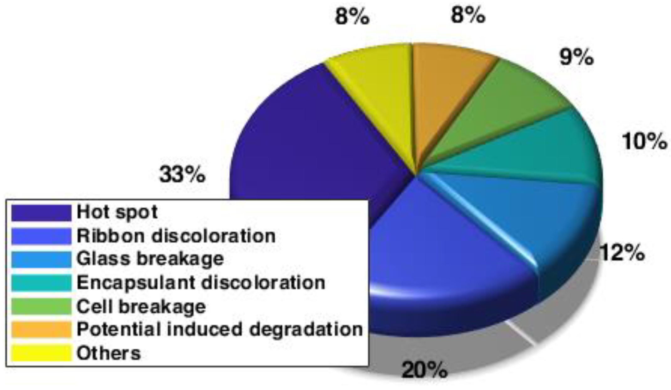
2.3. Solar Panel Power Loss Quantitative Estimation

Quantifying solar panel efficiency decrease is an important issue in investment and maintenance planning. It is interesting to estimate the efficiency losses due to degradation and pollution. In most cases, however, both phenomena are present, complicating their separate quantification.
In [45], an efficient algorithm is proposed that allows iterative decomposition of the measured performance indicator time series into three constituents: pollution, degradation, and seasonal elements.
The method described in [46] can also be used to estimate degradation and contamination over time. In this case, the time series of energy production is used for quantification. The proposed algorithm is based on an annual degradation rate analysis, combined with a random rate and results of a recovery soiling investigation.

3. Alleviation Methods against Diminishing the Energy Conversion Efficiency in Solar Panels

As could be seen previously, several issues can lead to a reduction in the efficiency of solar panels. There are multiple reasons for these. The related mitigation methods are correspondingly diverse.

3.1. Solar Panel Maintenance

Most of the issues diminishing the energy conversion capability of the solar panels, detailed in Section 2, are irreversible (excepting diverse depositions on the solar panel surface). Therefore, most of the research in this field is focusing on preventing such faults. Thus, a key measure in assuring the maximum extractable electrical power from solar cells is their maintenance.

3.1.1. Maintenance Methods

As in the case of the maintenance of any industrial equipment, also for solar panels, there are five main maintenance categories, as [47,48]:
  • Preventive maintenance usually covers physical inspections following the prescriptions from the operations manuals. It can be performed based on an inspection plan comprising daily up to yearly scheduled tasks [49]. These are related to the visual inspection of the solar cells to observe degradations and soiling, and to infrared thermography for the detection of hot/cold spots. Furthermore, quantitative examination can be useful, such as current–voltage characteristics and insulation resistance analysis [39,50].
  • Corrective maintenance tasks are accomplished after the occurrence of solar panel faults to bring them back to their initial working state [51]. In the frame of these tasks, the workers may tighten loose cable connections, replace faulted cells, fix control and positioning system faults, etc.
  • Predictive maintenance is a condition-based activity based on monitoring, analysis, and evaluation of the principal parameters of solar panels.
  • Additional maintenance comprises activities performed for keeping the solar panels clean and shadeless [52]. For this purpose, dedicated shade measurement tools can also be used.
  • Extraordinary maintenance is needed when unpredictable events take place, such as calamities, the need to move the panels, or changes required by regulation modifications [53].
Predictive maintenance is nowadays the most modern and fashionable safeguarding measure used in all the fields of industry. Using this method, the condition (health, status, and performance) of the equipment can be followed even in real-time. Its use can diminish exploitation costs by eliminating expensive unanticipated failures and securing the personnel to perform corrective maintenance tasks based on a well-planned schedule [54].
Even if predictive maintenance measures imply extra costs, they can partially mitigate the efficiency reduction in solar cells.

3.1.2. Condition Monitoring

Condition monitoring is the key activity on which predictive maintenance is based. This can be performed manually, which is a cheap approach, but it assures only low detection precision.
The most traditional technique applied is thermal imaging by using specific cameras. Solar thermography, by indicating places with excessive overtemperature, makes it possible to detect several solar panel faults, such as damaged cells, hot spots, and fire hazards [55,56]. On the one hand, this condition-monitoring method has several advantages, as it is non-destructive (hence it is safe for both inspection workers and the solar panels), needs only portable equipment, and can be performed in real-time. On the other hand, the cost of the imagining equipment must be considered, and the obtained images can be interpreted only by adequately instructed personnel [57].
For the solar panel surface temperature monitoring tasks another viable method is radiometry, which makes it possible to measure the electromagnetic radiation. By applying specific sensors, the infrared energy emitted by the solar panel surface can be transformed into an electrical signal proportional to the surface temperature. By using this approach, the same solar panel faults can be detected as those in the previous case [58]. For this purpose, other visual inspection methods can also be applied, such as infrared (IR), electroluminescence (EL), ultraviolet (UV) fluorescence imaging, etc. [59].
By monitoring the current and voltage of the solar panel strings, significant information on the electrical state of the solar panels can be obtained [60]. An advanced condition monitoring method, detailed in [61,62], is using exclusively measured I–V curves, without requiring the knowledge of the local operation circumstances related quantities, such as irradiance and temperature. The method is based on the simple single diode mathematical model of the solar panel. From the measured signals, the parameters of the model can be computed in real-time. Changes in their values can denote the degradation and aging of the solar panel.
Better detection accuracy can be achieved by means of more advanced methods, including artificial intelligence (AI)-based methods. For example, there are the failure modes and effects analysis (FMEA) [63,64] or the methods applying machine learning, including artificial neural network (ANN)-based methods [65,66], and deep learning [67] approaches.
The effective use of the monitoring results has the potential of reducing the influence of prospective faults in the solar panels, and consequently, increasing the efficiency of the energy conversion [39].
The highest detection accuracy (but at the greatest costs) can be reached only by using monitoring based on real-time sensors. These can measure solar irradiance, temperature, open-circuit voltage, and short circuit current from which the solar panel efficiency can be easily computed [39,68,69]. The diverse sensors applied for monitoring the solar panels (including remotely) can be connected to wireless sensor networks [70], or the Internet of Things (IoT) approach can also be applied [71].
The measured (observed) electrical outputs can also be used for increasing the electric power generation of the solar panels. These signals can be permanently compared with simulations or values obtained from neighboring solar panels (i.e., sister panels). Using the obtained information, the control system of the solar panel can act properly to maximize the converted power [47,60]. For this, it is very important to have correct input solar power predictions, based on precise weather forecasts. For this purpose, diverse mathematical models can be applied, which incorporate historic weather data and statistical weather prognostication units [72].

3.2. Technical Methods to Be Applied

To minimize the photovoltaic panel’s degradation and efficiency loss, a great diversity of measures can be applied.

3.2.1. Improving Solar Panel Structure and Quality

The divided cell approach seems the simplest and the more promising technical solution to reduce several causes of the diminishing of the solar panel efficiency over time. By cutting the cells of traditional size into two, three, or even four smaller units, employing the so-called cleaving process, the new cell segments will deliver the same voltage, but a current divided by the number of the cell segments. These measures translate into diminished losses and improved tolerance against long cracks and partial shading. The current reduction contributes to the eventual diminution of hot spots, too [73,74]. The lower-leakage currents will result in a decrease in the PID risks.
Multiple-cut solar cells obviously have drawbacks, too. Their manufacturing is challenging. It needs significant investments for the new production lines, but the payback period is relatively short due to the reduction in the cost per watts thanks to the increase in the output power per square meter. Constituting the solar panel with more cells of less surface results in more contacts, which increases the probability of contact faults. Despite these disadvantages, this approach seems to be a future basic standard in solar panel manufacturing [75].
Snail track degradations can be also minimized by optimizing the combinations of the used materials. As the silver nanoparticles are the main causes of the snail trails [76], special attention has to be paid to the encapsulation materials since they play an important role in the formation of silver acetate and silver phosphate [77].
Through a specific design of the busbars and fingers, the microcracks, snail trails, and also other degradations can be limited [78]. The simplest, already incorporated approach is the alternation of horizontal and vertical fingers. Thus, the possible length of these tracks can be radically reduced.
Due to the advancement of technology, the multi-cut cell approach is spreading. If the cell is cut in half or into one-third, the string current will also decrease to half or one-third, resulting in lower temperature when shadowing and also diminishing the PID risk. Meanwhile, more and more full-line busbars are printed onto the cell. This results in a smaller space between them, thus minimizing both the finger resistance losses and the risk of microcracks and snail tracks [79].
In [80], the M10 (182 × 182 mm²) and G12 (210 × 210 mm²) mono wafer formats are expected to become dominating in the market in the next years. These typically have between 9 and 12 busbars, meaning a very low busbar distance.
The multi-busbar (MBB) technology enables a great variety of solar panel structures. The two basic design parameters (the busbar width and finger spacing) can be optimized for minimizing both electrical and optical losses while keeping these dimensions as low as possible for limiting the possible paths of the microcracks and snail tracks [81].
There are also busbar-free solar panels, those with overlaid (so-called shingled) cell segments (strips). These are stuck together using a special flexible electrically conductive adhesive (ECA). Thus, ribbons, busbars, and the need for soldering are avoided. The lack of interconnection elements covering the solar panel surface results in a higher power per square meter than conventional solar panels and the ohmic losses of connections is reduced. This way the silver paste usage and the potential for snail trails are eliminated [82].
Solar panel degradation due to mechanical or material weaknesses can be minimized by applying improved designs, manufacturing technologies, and materials of better properties. More careful quality control can also limit the reduction in solar panel efficiency.
Microcracks or other material defects in solar panels introduced during manufacturing can be detected through the photographic surveying of electroluminescence (EL) [83]. Automated visual quality testing processes can be used to screen out imperfect solar cells and their connections to avoid future hot spots in the field. The use of reinforced glass materials can balance solar panel mass with strength, to increase reliability, inclusively during its handling [84]. By an optimized design of the frames with sloping profiles and drainage channels, the water can be more rapidly eliminated from the solar panel surface, while also cleaning away dust and other debris. These are only a very few measures to be undertaken by the manufacturers. Of course, all these procedures increase the fabrication costs and implicitly the final price of the solar panels.

3.2.2. Cooling of the Solar Panels

Overheating of photovoltaic panels can significantly reduce their efficiency of energy conversion. The cooling of solar panels can only be achieved by using additional equipment. For this purpose, several active and passive cooling systems have been proposed in the literature [85,86,87].
Passive cooling can be performed with air, or water, but also by employing conductive cooling. The easiest and most common method is to place a cooling surface on the back of the solar panel. These can be simple heatsinks, or more complex heating devices also used in other industries, such as heat pipes or heat exchangers [88,89].
More efficient cooling can only be achieved with an active system. These can use forced (ventilated) air or sprayed coolant for cooling the panel’s active surface, but also forced water circulation to cool the aforementioned heat pipes and heat exchangers [90].
All these technical solutions, however, increase the material requirements. The active cooling solutions also need additional energy for the pumps or fans.

3.2.3. Applying Bypass Diodes

Connecting passive bypass diodes to the solar panel, as shown in Figure 9, avoids shadowing effects and the resulting hot spot issues. If the solar cell becomes reverse biased due to shading, it will directly bias the bypass diode. The diode, as its name implies, will ensure a bypass path for current flow. When the shadow disappears, the solar cell returns to its initial biased state and the diode returns to its original reverse biased condition. Thus, fully illuminated solar cells are not disturbed by shaded cells [17].

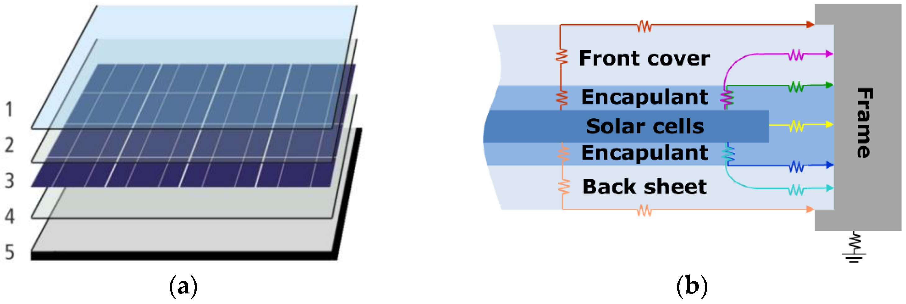
3.2.4. Mitigating PID

As mentioned earlier, PID is the most serious problem of photovoltaic panel degradation. Therefore, many solutions have been proposed in the literature to alleviate this situation.
The easiest way to reduce the PID effect is to place the panels (with certain limitations of course) in a place with lower temperature and humidity. Windy locations are also beneficial, as solar panels can be kept cooler.
It is quite possible to use so-called anti-PID photovoltaic installations. As for the solar panels themselves, they may contain higher volume resistivity encapsulants, such as improved EVA, polyvinyl butyral (PVB), thermoplastic polyurethane (TPU), thermoplastic polyolefin (TPO), or ionomers [91,92]. The use of a suitable extra SiO2 antireflection coating layer or back-sheets with higher breathability properties can both improve the PID resistance of the solar panels [91,93]. The widely applied soda-lime silicate glass covering the solar panels, which contributes favorably to the PID effects due to their substantial content of alkali ions, can be replaced by chemically strengthened aluminosilicate glass or thermally tempered soda-lime glass [19,94]. Using another approach, a thin TiO2 coating (such as those used for self-cleaning) is deposited on the cell side of the front glass to suppress the drift of metal ions. Unfortunately, the supplementary extra layer reflects, scatters, and absorbs the incident light, and thus diminishes the optical performance of the solar panel [95]. PID can be mitigated on glass level also by interrupting the glass surface and decreasing its conductivity with glass strips or different chemical agents [19].
PID mitigation is also crucial in the case of the passivated emitter and rear contact (PERC) solar panels, which are built of cells with an extra layer on their back side, which enables more sunlight to be captured and converted into electrical energy [96]. In [97], it was demonstrated that by applying a SiNx/SiOxNy stack as the front side antireflection layer and an AlOx/SiOxNy/SiNx stack layer as the rear-side passivation layer, significant improvement of the solar panel anti-PID performance was accomplished, while its efficiency was increased, too. In another performed study, it was shown that a very good PID mitigation characteristic can be achieved if in the antireflection layer a SiO2 film is placed between the SiNx layer and the p–n junction [98].
Improvements in the power electronic devices used in solar energy conversion can also lead to an enhanced PID resistance of the solar panels.
In another approach, inverters with built-in charge equalizers can be used [99]. These off-the-shelf devices (also called PID boxes) can control and invert the PID. The charge equalizer circuits are placed between the solar panels and the inverter. When the panel is not illuminated (e.g., at night), an opposite DC bias is applied to the panel, so the polarization charge is reversed and the PID effect is almost totally eliminated [100].
An alternative power electronics related PID mitigation method is using an individual micro-inverter for each solar module. Consequently, the voltage of each module can be easily optimized, and the panel can work at lower string voltages and thus diminish the PID [101].
Adequate grounding of the photovoltaic panels can also prevent the negative effects of PID. For this method, solar panels without imposed grounding constraints and connection to the grid without transformers are needed. In this case, the negative inverter pole can be grounded by a high-value resistor (typically of 22 kΩ). This approach prevents PID from appearing in the future, but there is no way to reverse its past effects.
It should be noted that the above technical solutions require additional investment.

3.2.5. Cleaning the Solar Panels

Rainwater cleans the surface of the photovoltaic energy converters naturally. This process is influenced by the local weather conditions and the tilt angle of the modules. Rain can only wash off non-adhered soil, but not the dirt on the panel surface [59,102].
All other cleaning methods to be detailed below imply additional operating and maintenance costs. When deciding whether cleaning is required, one has to weigh up to 7% annual energy conversion losses, totaling 7 billion EUR, and cleaning costs of 0.1–10 EUR/m² [36,103].
Manual cleaning is the most common method to restore a solar panel to its soil-free state. Even the toughest dirt can be removed by using it. Both dry and wet methods can be used.
During dry cleaning, dirt can only be removed by friction, which can damage (scratch) the surface of the solar panels. Therefore, only soft bristles and cloths can be used. Manual cleaning is unsafe for solar panels installed at high altitudes and impractical for offshore solar installations. Experience has shown that using this cleaning method does not fully restore the transparency of the glass covering the solar panels [59,104].
In terms of cleaning quality, water-based techniques seem to be more effective. On the other hand, this process requires a lot of water and energy. Therefore, it should only be used in non-arid or water-rich areas. Wet cleaning puts solar panels at risk from water clogging and thermal shock [59].
There are also mechanical methods for cleaning solar panels. Various methods have been proposed for this purpose, such as wipers, fans, brushes and water tanks with sprinklers, removable covers, etc. Deposited dust can be removed by blowing, vibrating or by ultrasonic means. These are usually driven by manually or automatically controlled electrical systems.
In a more expensive, electrostatic approach, electrodynamic screens (EDSs) are used for keeping the solar panels free of dust. The electrodes of the screen are supplied by high voltage and, consequently, the dust particles are detached and leap off from the panel surface [59,105].
If the cleaning costs are increasing, the final price of the converted solar energy is growing, too. Therefore, it is very important to find the optimum schedule for the cleaning since both cleaning costs and production losses depend on the cleaning frequency. Cleaning too frequently actually reduces solar panel losses but increases the maintenance costs. Rare cleaning results in low maintenance costs but decreases the efficiency of the energy conversion (see Figure 10) [106].
Practically, it is a complicated task to predict the precise schedule for the cleaning since this depends on a lot of factors that are difficult to predict, such as the rate of the dirt particle deposition, and weather conditions (rain and snow intensity and frequency, wind speed and direction, relative humidity, etc.). Therefore, complex installation site-dependent models are needed for the estimation of the optimal cleaning schedule [107,108]. Fortunately, the users have at their disposal off-the-shelf software products assisting them in finding out when the solar panels must be cleaned [106,109].

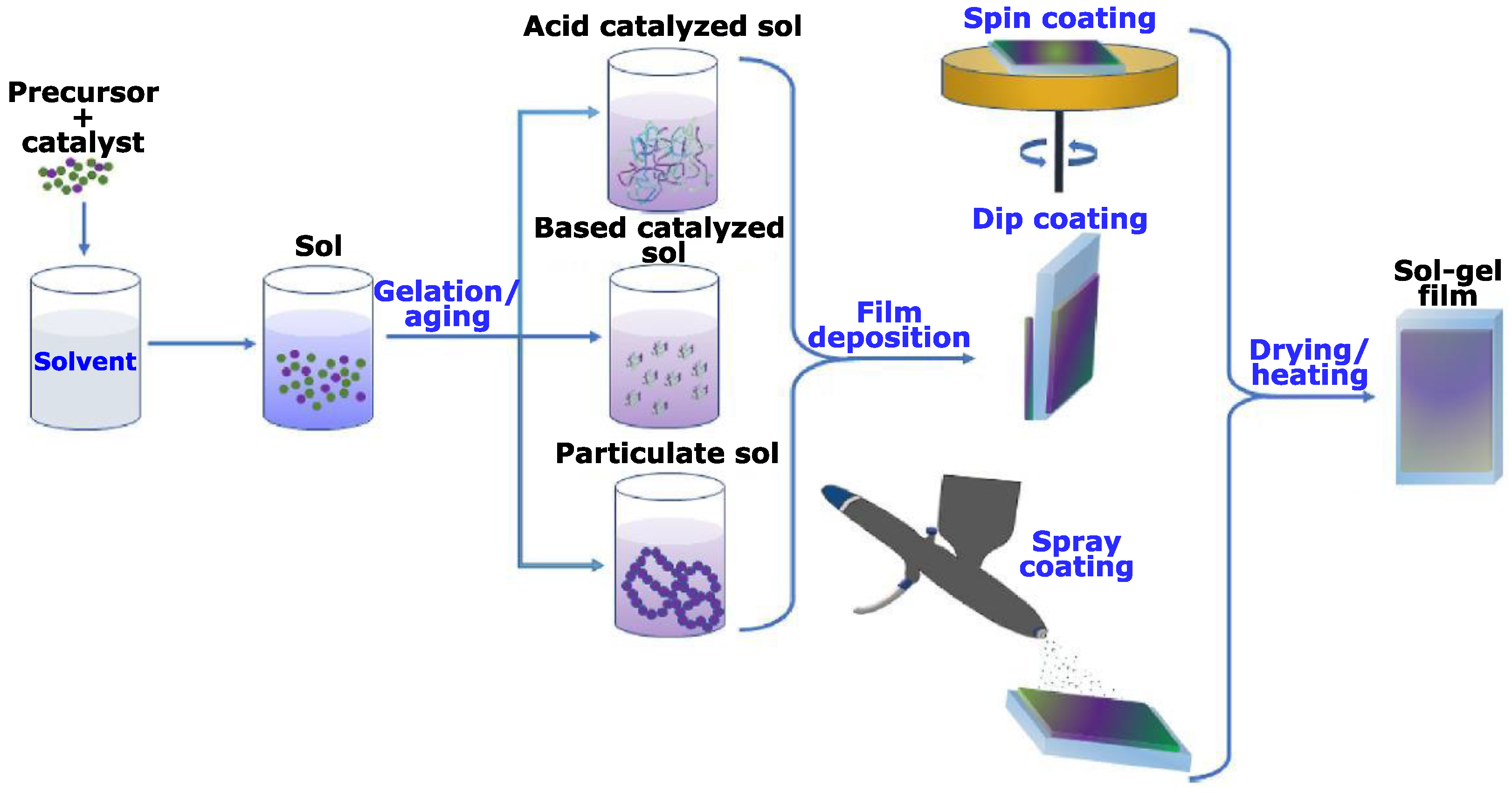
3.2.6. Self-Cleaning the Solar Panels

As could be seen, any previously mentioned solar panel cleaning method implies significant maintenance costs, which are diminishing the benefits of these actions performed for the improvement of the solar energy conversion.
Self-cleaning can be a promising solution to avoid or at least radically reduce permanent maintenance costs related to solar panel cleaning. The basic idea is to cover the solar panel with layers made of particular materials with the intrinsic ability to remove any soil from their surfaces. Most of these special features of the surfaces is bioinspired.
The self-cleaning surfaces which can be used in the soil deposition protection of solar panels may have water-repelling (hydrophobic) or water-dispersing (hydrophilic) properties. The wettability of the solar panel surface is the secret of self-cleaning. This is characterized by the contact angle and the hysteresis contact angle.
When a droplet comes into contact with a surface, it forms a dome-like shape. The angle formed between the surface and the tangent line to the droplet edge is the contact angle, also called the wetting angle, marked with θ in Figure 11. High wettability of a surface means that there is high surface energy that causes a strong attractive force pulling the liquid droplet down into a shape with a low contact angle. The contact angle hysteresis can be explained through a droplet placed on a tilted surface, as can be seen in Figure 11. As the droplet moves downhill, it will both advance (on the downhill side) and recede (on the other side), while its outer surface will distort to a shape with different advance (θa) and recede (θr) contact angles. Their difference is the so-called hysteresis. When the surface tilting or the droplet size is increased, gravity will win, and the droplet will begin to move downhill [110].
They are two approaches for protecting the solar panel from soiling: covering it with a hydrophobic (water-repelling) or hydrophilic (water-dispersing) layer.
The hydrophobic layer must assure a contact angle of the water droplets greater than 90°. Upon more advanced approaches, superhydrophobic surfaces can be applied, where the contact angle can exceed 150°, and the difference between the advance and recede contact angles must be less than 10°. When raindrops fall on such surfaces, they can easily flow off. Thus, water washes away the adhered soiling and the surface of the solar panel is cleaned without any manual intervention. Of course, this method can radically improve the efficiency of the man-made water cleaning systems [59,111].
Hydrophilic surfaces have a strong tendency to attract water. In this self-cleaning approach, the water droplets spread on the solar panel surface, move deep inside the soil, and moves it away [59]. Most of the super-hydrophilic self-cleaning coatings are composited of titania (TiO2). This is widely applied due to its outstanding photocatalytic properties, wide bandgap, chemical resistance, and photostability [112].
In the case of such coatings, self-cleaning is performed in two steps. During the first, the photocatalytic stage, the TiO2 film coating under the ultraviolet light reacts with the organic dirt and fragments it. Later, due to the hydrophilic property of the TiO2 layer, the rainwater will be able to disperse over the entire surface of the solar panel and wash the soil away [105].
These coatings are exposed to friction both during the mechanical cleaning and by scratchy depositions (dust, sand, and other soiling agents). Therefore, their surface must be adequately protected [113]. For this purpose, low free-energy hydrophobic surfaces were designed, optimized, and tested, which exhibit anti-adhesion properties and accomplish the required mechanical properties [114].
The self-cleaning coatings are frequently combined with antireflective layers. It is well-known that, generally, more than 30% of incident light is uncaptured since it is reflected from the surface of the solar panels, radically decreasing their global efficiency. Therefore, to reduce this effect, anti-reflection coatings made of SiO2, MgF2, TiO2, Si3N4, and ZrO2 materials are proposed [111,115]. By applying nanostructured TiO2 coatings, both the self-cleaning and reflection reduction can be solved together [116].
There are numerous chemical approaches for producing self-cleaning surfaces, but the sol-gel-based method is the most widespread since it enables good control of the created surfaces and of optical properties [117,118]. The sol-gel coatings can be deposited on the solar panels by using a great variety of techniques, such as spin-coating [119], dip-coating [120], spray deposition, thermal evaporation, etc. [111,121], as can be seen in Figure 12.
Despite extensive huge research efforts made in this field, the technology is not yet mature. The self-cleaning surfaces so far have poor dispersion and adhesion. Moreover, they often have low density and require a demanding annealing procedure at high temperatures to achieve the required uniform coating [121,122].

4. Discussion

As can be seen, the diminishing efficiency during the exploitation time of solar panels is inevitable. Without taking any measures, their degradation rate can be significant and can lead to considerable financial losses.
There are several reasons for degradation about which the users cannot do anything (such as cracks, delamination, hot spots, corrosion, etc.). Besides these, several technical issues (such as PID or overheating) can diminish the efficiency. Their risk can be limited by applying extra technical measures (coolers, bypass diodes, etc.).
These, however, cannot replace the adequate mandatory maintenance of the installed solar panels. The key maintenance task is keeping the active surface of the solar panels clean, or else the solar energy conversion takes place at very low efficiency. This can be achieved in a great diversity of ways from simple dry cleaning, which can be executed by anybody with easy access to the solar panel, to applying the most advanced achievements of chemistry regarding self-cleaning surfaces.
Three basic cleaning methods have been identified in the paper: dry and wet mechanical cleaning and applying self-cleaning coatings on the solar panel surface.
The selection of the most adequate cleaning method depends on several features, such as:
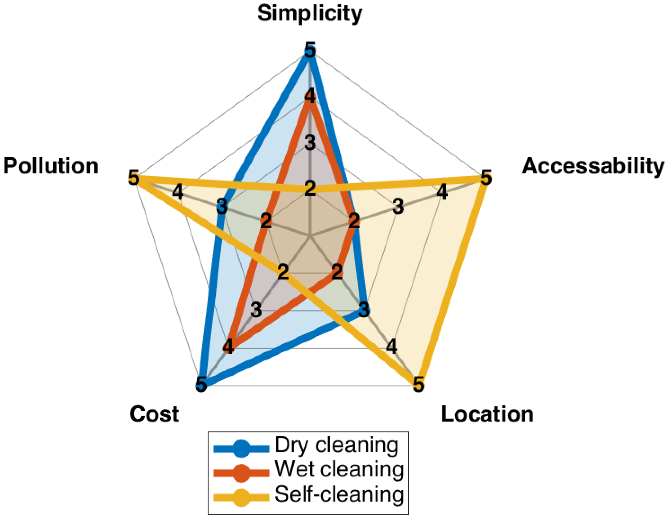
  • Simplicity (concerning both the needed materials, tools and the required skills of the operating person). The dry cleaning is the most undemanding method, while the most complicated is the panel surface coating (both concerning technology and required research groundwork).
  • Accessibility depends on the placement of the solar panels. Obviously, where the solar panels were mounted in remote or difficult-to-access places, manual cleaning methods cannot be considered.
  • Geographical and environmental aspects. In locations with heavy rains, solar panel cleaning is not intensive work. On the contrary, in desert areas with significant sand/dust depositions the self-cleaning surfaces cannot cope with the great quantity of depositions. In such cases, the wet method should be the most adequate, but in several circumstances in such areas water is radically missing or needed for drinking.
  • Cost-related issues are mandatory to be primary considerations in any application. Of course, dry cleaning is the most efficient from this point of view since it requires only simple and cheap tools. The exigent self-cleaning methods are the lowest ranked upon this criterion.
  • Environmental issues are also very important to be considered. Wet cleaning methods need a great quantity of precious water and the dirty water remaining after washing the solar panels must be also treated. Meanwhile, the self-cleaning surfaces do not pollute at all the environment, at least locally where the solar panels are placed.
Based on all these findings, a graphical comparison of the three main cleaning approaches was developed (see Figure 13). The following five levels of the Likert scale were considered: 1: very weak; 2: weak; 3: fair; 4: strong and 5: very strong.
As it can be seen, wet cleaning is the lowest ranked cleaning method, at least based on the considered features.
The others are ranked nearly the same. The self-cleaning approach is the best solution for three features (location, accessibility, and environmental pollution), so it is highly recommended in all situations where the dirt depositions are very intensive.

5. Conclusions

Solar energy is a practically infinite sustainable energy resource, with massive potential in electric power generation and heating. Solar energy conversion systems do not generate any air pollution or greenhouse gases; thus, they are very beneficial for the environment. This is the reason why the wide spread of solar energy converters is so rapid around the world.
Unfortunately, solar panels also have drawbacks, such as their low efficiency and the diminishing of their energy conversion capability during their lifetime. Consequently, keeping their efficiency as high as possible over the years is a critical issue that needs to be addressed. The paper tries to help specialists in understanding the reasons for efficiency decrease and to update them on the possible alleviation methods.
The future efficient use of solar panels strongly depends on where and how these are placed. In most cases, a wrong placement cannot be corrected in the future. For the right decision, it is not enough to consider only the solar illumination, but also the environmental effects, which can drastically reduce the efficiency of the solar energy conversion.
The solar panels’ degradation progress (both initial and long-lasting) depends not only on environmental issues but also on the construction and quality of the solar panels. Therefore, if a long-term great power gain is desired, only solar panels of very good quality must be considered.
Even if the best solar panels are used and they are placed optimally from all the considerations, the users must take care of their adequate maintenance. This process is strongly assisted by advanced condition-monitoring methods, also detailed in this paper.
During the exploitation of solar panels, the main duty of the user is to keep them clean, since in time a great diversity of depositions can cover the active surface of the solar panels. For this critical issue, the paper presents various cleaning methods of diverse complexity and costs. The correct decision on which cleaning method to be applied strongly depends on what kind of depositions are on the solar panel, the local weather conditions, their accessibility, and naturally on the available budget of the users.
The authors hope that the plenitude of information collected in this paper can be helpful for all the people interested in this field, where significant research efforts are made in our times, and where radical improvements can be expected in a near future.

Funding

This research received no external funding.

Data Availability Statement

Not applicable.

Conflicts of Interest

The authors declare no conflict of interest.

References

  1. Smil, V. World History and Energy. In Encyclopedia of Energy; Elsevier Science: Amsterdam, The Netherlands, 2004; Volume 6, pp. 549–561. [Google Scholar]
  2. Szabó, L. The history of using solar energy. In Proceedings of the 7th International Conference on Modern Power Systems (MPS 2017), Cluj-Napoca, Romania, 6–9 June 2017. [Google Scholar] [CrossRef]
  3. Victoria, M.; Haegel, N.; Peters, I.M.; Sinton, R.; Jäger-Waldau, A.; del Cañizo, C.; Breyer, C.; Stocks, M.; Blakers, A.; Kaizuka, I. Solar photovoltaics is ready to power a sustainable future. Joule 2021, 5, 1041–1056. [Google Scholar] [CrossRef]
  4. Solar Continues to Break Installation Records, on Track for Terawatt Scale by 2022. Available online: https://www.solarpowereurope.org/solar-continues-to-break-installation-records-on-track-for-terawatt-scale-by-2022/ (accessed on 22 January 2022).
  5. Herceg, S.; Pinto Bautista, S.; Weiß, K.-A. Influence of waste management on the environmental footprint of electricity produced by photovoltaic systems. Energies 2020, 13, 2146. [Google Scholar] [CrossRef]
  6. Modrzynski, C.; Blaesing, L.; Hippmann, S.; Bertau, M.; Bloh, J.Z.; Weidlich, C. Electrochemical recycling of photovoltaic modules to recover metals and silicon wafers. Chem. Ing. Tech. 2021, 93, 1851–1858. [Google Scholar] [CrossRef]
  7. Schoden, F.; Dotter, M.; Knefelkamp, D.; Blachowicz, T.; Schwenzfeier-Hellkamp, E. Review of state of the art recycling methods in the context of dye sensitized solar cells. Energies 2021, 14, 3741. [Google Scholar] [CrossRef]
  8. Jordan, D.C.; Silverman, T.J.; Wohlgemuth, J.H.; Kurtz, S.R.; VanSant, K.T. Photovoltaic failure and degradation modes. Prog. Photovolt. Res. Appl. 2017, 25, 318–326. [Google Scholar] [CrossRef]
  9. Lindroos, J.; Savin, H. Review of light-induced degradation in crystalline silicon solar cells. Sol. Energy Mater. Sol. Cells 2016, 147, 115–126. [Google Scholar] [CrossRef]
  10. Schmidt, J.; Bredemeier, D.; Walter, D.C. On the defect physics behind light and elevated temperature-induced degradation (LeTID) of multicrystalline silicon solar cells. IEEE J. Photovolt. 2019, 9, 1497–1503. [Google Scholar] [CrossRef]
  11. Bernardini, S.; Saynova, D.; Binetti, S.; Coletti, G. Light-induced degradation in compensated mc-Si p-type solar cells. In Proceedings of the 38th IEEE Photovoltaic Specialists Conference (PHSP 2012), Austin, TX, USA, 4 October 2012; pp. 3242–3247. [Google Scholar] [CrossRef]
  12. Witteck, R.; Schulte-Huxel, H.; Veith-Wolf, B.; Vogt, M.R.; Kiefer, F.; Kontges, M.; Peibst, R.; Brendel, R. Reducing UV induced degradation losses of solar modules with c-Si solar cells featuring dielectric passivation layers. In Proceedings of the 44th Photovoltaic Specialist Conference (PVSC 2017), Washington, DC, USA, 25–30 June 2017; pp. 1366–1370. [Google Scholar] [CrossRef]
  13. Kim, M. Understanding the Mechanisms of Light-Induced Degradation in Crystalline Silicon. Ph.D. Thesis, University of New South Wales, Sydney, NSW, Australia, 2020. [Google Scholar]
  14. Kim, J.; Rabelo, M.; Padi, S.P.; Yousuf, H.; Cho, E.-C.; Yi, J. A review of the degradation of photovoltaic modules for life expectancy. Energies 2021, 14, 4278. [Google Scholar] [CrossRef]
  15. Da Fonseca, J.E.F.; de Oliveira, F.S.; Prieb, C.W.M.; Krenzinger, A. Degradation analysis of a photovoltaic generator after operating for 15 years in southern Brazil. Sol. Energy 2020, 196, 196–206. [Google Scholar] [CrossRef]
  16. Virtuani, A.; Caccivio, M.; Annigoni, E.; Friesen, G.; Chianese, D.; Ballif, C.; Sample, T. 35 years of photovoltaics: Analysis of the TISO-10-kW solar plant, lessons learnt in safety and performance—Part 1. Prog. Photovolt. Res. Appl. 2019, 27, 328–339. [Google Scholar] [CrossRef]
  17. Vieira, R.G.; de Araújo, F.M.; Dhimish, M.; Guerra, M.I. A comprehensive review on bypass diode application on photovoltaic modules. Energies 2020, 13, 2472. [Google Scholar] [CrossRef]
  18. Wang, Y.; Itako, K.; Kudoh, T.; Koh, K.; Ge, Q. Voltage-based hot-spot detection method for photovoltaic string using a projector. Energies 2017, 10, 230. [Google Scholar] [CrossRef]
  19. Luo, W.; Khoo, Y.S.; Hacke, P.; Naumann, V.; Lausch, D.; Harvey, S.P.; Singh, J.P.; Chai, J.; Wang, Y.; Aberle, A.G. Potential-induced degradation in photovoltaic modules: A critical review. Energy Environ. Sci. 2017, 10, 43–68. [Google Scholar] [CrossRef]
  20. Pingel, S.; Frank, O.; Winkler, M.; Daryan, S.; Geipel, T.; Hoehne, H.; Berghold, J. Potential induced degradation of solar cells and panels. In Proceedings of the 35th IEEE Photovoltaic Specialists Conference (PVSC 2010), Honolulu, HI, USA, 20–25 June 2010; pp. 2817–2822. [Google Scholar] [CrossRef]
  21. Hybrid Solar Panel Structure. Available online: https://commons.wikimedia.org/wiki/File:Hybrid_Solar_Panel_Structure.jpg (accessed on 23 February 2022).
  22. Nagel, H.; Glatthaar, M.; Glunz, S.W. Quantitative assessment of the local leakage current in PV modules for degradation prediction. In Proceedings of the 31st European PV Solar Energy Conference and Exhibition, Hamburg, Germany, 14–18 September 2015. [Google Scholar] [CrossRef]
  23. El-Gharbawy, A. Review on corrosion in solar panels. Int. J. Smart Grid-IjSmartGrid 2018, 2, 218–220. [Google Scholar] [CrossRef]
  24. Köntges, M.; Kurtz, S.; Packard, C.; Jahn, U.; Berger, K.A.; Kato, K.; Friesen, T.; Liu, H.; Iseghem, M.V. Performance and Reliability of Photovoltaic Systems. Subtask 3.2: Review of Failures of Photovoltaic Modules. Research Report IEA PVPS Task 13. Available online: https://iea-pvps.org/key-topics/review-of-failures-of-photovoltaic-modules-final/ (accessed on 18 February 2022).
  25. De Oliveira, M.C.C.; Cardoso, A.S.A.D.; Viana, M.M.; Lins, V.d.F.C. The causes and effects of degradation of encapsulant ethylene vinyl acetate copolymer (EVA) in crystalline silicon photovoltaic modules: A review. Renew. Sustain. Energy Rev. 2018, 81, 2299–2317. [Google Scholar] [CrossRef]
  26. Hasan, A.A.; Ahmed Alkahtani, A.; Shahahmadi, S.A.; Alam, N.E.; Islam, M.A.; Amin, N. Delamination-and electromigration-related failures in solar panels—A review. Sustainability 2021, 13, 6882. [Google Scholar] [CrossRef]
  27. Dobra, T.; Vollprecht, D.; Pomberger, R. Thermal delamination of end-of-life crystalline silicon photovoltaic modules. Waste Manag. Res. 2021, 40, 96–103. [Google Scholar] [CrossRef]
  28. Wohlgemuth, J.H.; Kempe, M.D.; Miller, D.C. Discoloration of PV encapsulants. In Proceedings of the 39th Photovoltaic Specialists Conference (PVSC 2013), Tampa Bay, FL, USA, 16–21 June 2013; pp. 3260–3265. [Google Scholar] [CrossRef]
  29. Gabor, A.M.; Schneller, E.J.; Seigneur, H.; Rowell, M.W.; Colvin, D.; Hopwood, M.; Davis, K.O. The impact of cracked solar cells on solar panel energy delivery. In Proceedings of the 47th IEEE Photovoltaic Specialists Conference (PVSC 2020), Virtual Meeting, 15–21 August 2020; pp. 0810–0813. [Google Scholar] [CrossRef]
  30. Dhimish, M.; Holmes, V.; Mehrdadi, B.; Dales, M. The impact of cracks on photovoltaic power performance. J. Sci. Adv. Mater. Devices 2017, 2, 199–209. [Google Scholar] [CrossRef]
  31. Bdour, M.; Dalala, Z.; Al-Addous, M.; Radaideh, A.; Al-Sadi, A. A comprehensive evaluation on types of microcracks and possible effects on power degradation in photovoltaic solar panels. Sustainability 2020, 12, 6416. [Google Scholar] [CrossRef]
  32. Ennemri, A.; Logerais, P.; Balistrou, M.; Durastanti, J.; Belaidi, I. Cracks in silicon photovoltaic modules: A review. J. Optoelectron. Adv. Mater. 2019, 21, 74–92. [Google Scholar]
  33. Meyer, S.; Richter, S.; Timmel, S.; Gläser, M.; Werner, M.; Swatek, S.; Hagendorf, C. Snail trails: Root cause analysis and test procedures. Energy Procedia 2013, 38, 498–505. [Google Scholar] [CrossRef]
  34. Hussain, A.; Batra, A.; Pachauri, R. An experimental study on effect of dust on power loss in solar photovoltaic module. Renew. Wind. Water Sol. 2017, 4, 1–13. [Google Scholar] [CrossRef]
  35. Bodnár, I.; Tóth, L.; Somogyiné Molnár, J.; Szabó, N.; Erdősy, D.; Boros, R. Examination the effect of environmental factors on a photovoltaic solar panel. In Solutions for Sustainable Development: Proceedings of the 1st International Conference on Engineering Solutions for Sustainable Development (ICESSD 2019), Miskolc, Hungary, 3–4 October 2019; Tóthné Szita, K., Jármai, K., Voith, K., Eds.; CRC Press: Boca Raton, FL, USA, 2019; pp. 108–114. [Google Scholar]
  36. Ilse, K.; Micheli, L.; Figgis, B.W.; Lange, K.; Daßler, D.; Hanifi, H.; Wolfertstetter, F.; Naumann, V.; Hagendorf, C.; Gottschalg, R. Techno-economic assessment of soiling losses and mitigation strategies for solar power generation. Joule 2019, 3, 2303–2321. [Google Scholar] [CrossRef]
  37. Mejia, F.; Kleissl, J.; Bosch, J. The effect of dust on solar photovoltaic systems. Energy Procedia 2014, 49, 2370–2376. [Google Scholar] [CrossRef] [Green Version]
  38. Yotham, A.; Pogrebnaya, T.; Kichonge, B. Effect of industrial dust deposition on photovoltaic module performance: Experimental measurements in the tropical region. Int. J. Photoenergy 2019, 2019, 1892148. [Google Scholar]
  39. Bosman, L.B.; Leon-Salas, W.D.; Hutzel, W.; Soto, E.A. PV system predictive maintenance: Challenges, current approaches, and opportunities. Energies 2020, 13, 1398. [Google Scholar] [CrossRef]
  40. Maghami, M.R.; Hizam, H.; Gomes, C.; Radzi, M.A.; Rezadad, M.I.; Hajighorbani, S. Power loss due to soiling on solar panel: A review. Renew. Sustain. Energy Rev. 2016, 59, 1307–1316. [Google Scholar] [CrossRef]
  41. Kennedy, J.; Lo, A.; Rajamani, H.-S.; Lutfi, S. Solar and sand: Dust deposit mitigation in the desert for PV arrays. Sustain. Energy Grids Netw. 2021, 28, 100531. [Google Scholar] [CrossRef]
  42. Solis, J.; Råberg, A.; André, J.; Nilsson, M. Analyzing the effect of snow in PV regulator response in a PV solar park. In Proceedings of the 9th International Conference on Smart Grid (icSmartGrid), Setubal, Portugal, 29 June–1 July 2021; pp. 72–75. [Google Scholar] [CrossRef]
  43. Solar Panels Covered by Sand. Available online: https://live.staticflickr.com/3204/2858555432_9918350e26_b.jpg (accessed on 23 February 2022).
  44. Solar Panels Covered by Snow. Available online: https://pixabay.com/photos/solar-covered-snow-snowy-5903373/ (accessed on 23 February 2022).
  45. Skomedal, Å.; Deceglie, M.G. Combined estimation of degradation and soiling losses in photovoltaic systems. IEEE J. Photovolt. 2020, 10, 1788–1796. [Google Scholar] [CrossRef]
  46. Deceglie, M.G.; Muller, M.; Jordan, D.C.; Deline, C. Numerical validation of an algorithm for combined soiling and degradation analysis of photovoltaic systems. In Proceedings of the 46th Photovoltaic Specialists Conference (PVSC 2019), Chicago, IL, USA, 16–21 June 2019; pp. 3111–3114. [Google Scholar] [CrossRef]
  47. Iftikhar, H.; Sarquis, E.; Branco, P. Why can simple operation and maintenance (O&M) practices in large-scale grid-connected PV power plants play a key role in improving its energy output? Energies 2021, 14, 3798. [Google Scholar] [CrossRef]
  48. Magee, S. Solar Photovoltaic Operation and Maintenance for Residential, Commercial and Utility Systems; CreateSpace Independent Publishing Platform: Scotts Valley, CA, USA, 2010. [Google Scholar]
  49. Baklouti, A.; Mifdal, L.; Dellagi, S.; Chelbi, A. An optimal preventive maintenance policy for a solar photovoltaic system. Sustainability 2020, 12, 4266. [Google Scholar] [CrossRef]
  50. Ji, D.; Zhang, C.; Lv, M.; Ma, Y.; Guan, N. Photovoltaic array fault detection by automatic reconfiguration. Energies 2017, 10, 699. [Google Scholar] [CrossRef]
  51. Rukijkanpanich, J.; Mingmongkol, M. Enhancing performance of maintenance in solar power plant. J. Qual. Maint. Eng. 2019, 26, 575–591. [Google Scholar] [CrossRef]
  52. Kazem, H.A.; Chaichan, M.T.; Al-Waeli, A.H.; Sopian, K. A review of dust accumulation and cleaning methods for solar photovoltaic systems. J. Clean. Prod. 2020, 276, 123187. [Google Scholar] [CrossRef]
  53. Amin, S.B.; Chowdhury, M.I.; Ehsan, S.A.; Iqbal, S.Z. Solar energy and natural disasters: Exploring household coping mechanisms, capacity, and resilience in Bangladesh. Energy Res. Soc. Sci. 2021, 79, 102190. [Google Scholar] [CrossRef]
  54. Lughofer, E.; Sayed-Mouchaweh, M. Predictive Maintenance in Dynamic Systems: Advanced Methods, Decision Support Tools and Real-World Applications; Springer: Cham, Switzerland, 2019. [Google Scholar]
  55. Gonzalo, A.P.; Marugán, A.P.; Márquez, F.P.G. Survey of maintenance management for photovoltaic power systems. Renew. Sustain. Energy Rev. 2020, 134, 110347. [Google Scholar] [CrossRef]
  56. Kandeal, A.; Elkadeem, M.; Thakur, A.K.; Abdelaziz, G.B.; Sathyamurthy, R.; Kabeel, A.; Yang, N.; Sharshir, S.W. Infrared thermography-based condition monitoring of solar photovoltaic systems: A mini review of recent advances. Sol. Energy 2021, 223, 33–43. [Google Scholar] [CrossRef]
  57. Herraiz, Á.H.; Marugán, A.P.; Márquez, F.P.G. A review on condition monitoring system for solar plants based on thermography. In Non-Destructive Testing and Condition Monitoring Techniques for Renewable Energy Industrial Assets; Papaelias, M., Márquez, F.P.G., Karyotakis, A., Eds.; Butterworth-Heinemann: Oxford, UK, 2020; pp. 103–118. [Google Scholar] [CrossRef]
  58. Márquez, F.P.G.; Ramírez, I.S. Condition monitoring system for solar power plants with radiometric and thermographic sensors embedded in unmanned aerial vehicles. Measurement 2019, 139, 152–162. [Google Scholar] [CrossRef]
  59. Santhakumari, M.; Sagar, N. A review of the environmental factors degrading the performance of silicon wafer-based photovoltaic modules: Failure detection methods and essential mitigation techniques. Renew. Sustain. Energy Rev. 2019, 110, 83–100. [Google Scholar] [CrossRef]
  60. Mallor, F.; León, T.; De Boeck, L.; Van Gulck, S.; Meulders, M.; Van der Meerssche, B. A method for detecting malfunctions in PV solar panels based on electricity production monitoring. Sol. Energy 2017, 153, 51–63. [Google Scholar] [CrossRef]
  61. Lappalainen, K.; Piliougine, M.; Spagnuolo, G. Experimental comparison between various fitting approaches based on RMSE minimization for photovoltaic module parametric identification. Energy Convers. Manag. 2022, 258, 115526. [Google Scholar] [CrossRef]
  62. Kalliojärvi-Viljakainen, H.; Lappalainen, K.; Valkealahti, S. A novel procedure for identifying the parameters of the single-diode model and the operating conditions of a photovoltaic module from measured current–voltage curves. Energy Rep. 2022, 8, 4633–4640. [Google Scholar] [CrossRef]
  63. Colli, A. Failure mode and effect analysis for photovoltaic systems. Renew. Sustain. Energy Rev. 2015, 50, 804–809. [Google Scholar] [CrossRef]
  64. Kut, P.; Pietrucha-Urbanik, K.; Tchórzewska-Cieślak, B. Reliability-oriented design of a solar-PV deployments. Energies 2021, 14, 6535. [Google Scholar] [CrossRef]
  65. Carvalho, D.V.; Pereira, E.M.; Cardoso, J.S. Machine learning interpretability: A survey on methods and metrics. Electronics 2019, 8, 832. [Google Scholar] [CrossRef]
  66. Herraiz, Á.H.; Marugán, A.P.; Márquez, F.P.G. Photovoltaic plant condition monitoring using thermal images analysis by convolutional neural network-based structure. Renew. Energy 2020, 153, 334–348. [Google Scholar] [CrossRef]
  67. Shapsough, S.; Zualkernan, I.; Dhaouadi, R. Deep learning at the edge for operation and maintenance of large-scale solar farms. In Smart Grid and Internet of Things. SGIoT 2020. Lecture Notes of the Institute for Computer Sciences, Social Informatics and Telecommunications Engineering; Lin, Y.B., Deng, D.J., Eds.; Springer: Cham, Switzerland, 2020; Volume 354, pp. 27–44. [Google Scholar]
  68. Beránek, V.; Olšan, T.; Libra, M.; Poulek, V.; Sedláček, J.; Dang, M.-Q.; Tyukhov, I.I. New monitoring system for photovoltaic power plants’ management. Energies 2018, 11, 2495. [Google Scholar] [CrossRef]
  69. López-Vargas, A.; Fuentes, M.; Vivar, M. IoT application for real-time monitoring of solar home systems based on Arduino™ with 3G connectivity. IEEE Sens. J. 2018, 19, 679–691. [Google Scholar] [CrossRef]
  70. Parikh, A.; Pathan, F.; Rathod, B.; Shah, S. Solar panel condition monitoring system based on wireless sensor network. Int. J. Sci. Eng. Technol. Res. 2015, 4, 4320–4324. [Google Scholar] [CrossRef]
  71. Badave, P.M.; Karthikeyan, B.; Badave, S.; Mahajan, S.; Sanjeevikumar, P.; Gill, G.S. Health monitoring system of solar photovoltaic panel: An internet of things application. In Advances in Smart Grid and Renewable Energy; SenGupta, S., Zobaa, A., Sherpa, K., Bhoi, A., Eds.; Springer: Berlin/Heidelberg, Germany, 2018; pp. 347–355. [Google Scholar]
  72. Vicente-Gabriel, J.; Gil-González, A.-B.; Luis-Reboredo, A.; Chamoso, P.; Corchado, J.M. LSTM networks for overcoming the challenges associated with photovoltaic module maintenance in smart cities. Electronics 2021, 10, 78. [Google Scholar] [CrossRef]
  73. Lim, J.R.; Shin, W.G.; Hwang, H.; Ju, Y.-C.; Ko, S.W.; Yoon, H.S.; Kang, G.H. Analytical study of the electrical output characteristics of c-Si solar cells by cut and shading phenomena. Energies 2018, 11, 3397. [Google Scholar] [CrossRef]
  74. Akram, M.W.; Li, G.; Jin, Y.; Zhu, C.; Javaid, A.; Akram, M.Z.; Khan, M.U. Study of manufacturing and hotspot formation in cut cell and full cell PV modules. Sol. Energy 2020, 203, 247–259. [Google Scholar] [CrossRef]
  75. Kopecek, R.; Libal, J. Bifacial photovoltaics 2021: Status, opportunities and challenges. Energies 2021, 14, 2076. [Google Scholar] [CrossRef]
  76. Meyer, S.; Timmel, S.; Richter, S.; Werner, M.; Gläser, M.; Swatek, S.; Braun, U.; Hagendorf, C. Silver nanoparticles cause snail trails in photovoltaic modules. Sol. Energy Mater. Sol. Cells 2014, 121, 171–175. [Google Scholar] [CrossRef]
  77. Duerr, I.; Bierbaum, J.; Metzger, J.; Richter, J.; Philipp, D. Silver grid finger corrosion on snail track affected PV modules–investigation on degradation products and mechanisms. Energy Procedia 2016, 98, 74–85. [Google Scholar] [CrossRef]
  78. Solar Cell Busbar: 3BB, 5BB or 0BB? Available online: https://sinovoltaics.com/technology/solar-cell-busbar-3bb-5bb-or-0bb/ (accessed on 29 August 2022).
  79. Braun, S.; Hahn, G.; Nissler, R.; Pönisch, C.; Habermann, D. Multi-busbar solar cells and modules: High efficiencies and low silver consumption. Energy Procedia 2013, 38, 334–339. [Google Scholar] [CrossRef]
  80. Fischer, M.; Woodhouse, M.; Herritsch, S.; Trube, J. International Technology Roadmap for Photovoltaic (ITRPV)—2021 Results; VDMA Photovoltaic Equipment: Frankfurt am Main, Germany, 2022. [Google Scholar]
  81. Panda, T.; Sadhukhan, S.; Acharyya, S.; Banerjee, P.; Nandi, A.; Bose, S.; Mondal, N.; Das, G.; Maity, S.; Chaudhuri, P. Impact of multi-busbar front grid patterns on the performance of industrial type c-Si solar cell. Sol. Energy 2022, 236, 790–801. [Google Scholar] [CrossRef]
  82. Klasen, N.; Weisser, D.; Rößler, T.; Neuhaus, D.H.; Kraft, A. Performance of shingled solar modules under partial shading. Prog. Photovolt. Res. Appl. 2022, 30, 325–338. [Google Scholar] [CrossRef]
  83. Fuyuki, T.; Kitiyanan, A. Photographic diagnosis of crystalline silicon solar cells utilizing electroluminescence. Appl. Phys. A 2009, 96, 189–196. [Google Scholar] [CrossRef]
  84. Deubener, J.; Helsch, G.; Moiseev, A.; Bornhöft, H. Glasses for solar energy conversion systems. J. Eur. Ceram. Soc. 2009, 29, 1203–1210. [Google Scholar] [CrossRef]
  85. Bevilacqua, P.; Perrella, S.; Cirone, D.; Bruno, R.; Arcuri, N. Efficiency improvement of photovoltaic modules via back surface cooling. Energies 2021, 14, 895. [Google Scholar] [CrossRef]
  86. Arifin, Z.; Suyitno, S.; Tjahjana, D.D.D.P.; Juwana, W.E.; Putra, M.R.A.; Prabowo, A.R. The effect of heat sink properties on solar cell cooling systems. Appl. Sci. 2020, 10, 7919. [Google Scholar] [CrossRef]
  87. Kim, J.; Nam, Y. Study on the cooling effect of attached fins on PV using CFD simulation. Energies 2019, 12, 758. [Google Scholar] [CrossRef]
  88. Szabó, L. Additive manufacturing of cooling systems used in power electronics. A brief survey. In Proceedings of the 29th International Workshop on Electric Drives: Improvement in Efficiency of Electric Drives (IWED 2022), Moskow, Rusia, 26–29 January 2022; p. 32. [Google Scholar] [CrossRef]
  89. Szabó, L. Survey on applying 3D printing in manufacturing the cooling systems of electrical machines. In Proceedings of the International Conference on Automation, Quality and Testing, Robotics (AQTR 2022), Cluj-Napoca, Romania, 21–22 May 2022. [Google Scholar] [CrossRef]
  90. Dwivedi, P.; Sudhakar, K.; Soni, A.; Solomin, E.; Kirpichnikova, I. Advanced cooling techniques of PV modules: A state of art. Case Stud. Therm. Eng. 2020, 21, 100674. [Google Scholar] [CrossRef]
  91. Virtuani, A.; Annigoni, E.; Ballif, C. One-type-fits-all-systems: Strategies for preventing potential-induced degradation in crystalline silicon solar photovoltaic modules. Prog. Photovolt. Res. Appl. 2019, 27, 13–21. [Google Scholar] [CrossRef]
  92. López-Escalante, M.; Caballero, L.J.; Martín, F.; Gabás, M.; Cuevas, A.; Ramos-Barrado, J. Polyolefin as PID-resistant encapsulant material in PV modules. Sol. Energy Mater. Sol. Cells 2016, 144, 691–699. [Google Scholar] [CrossRef]
  93. Dhimish, M.; Hu, Y.; Schofield, N.; G Vieira, R. Mitigating potential-induced degradation (PID) using SiO2 ARC layer. Energies 2020, 13, 5139. [Google Scholar] [CrossRef]
  94. Kambe, M.; Hara, K.; Mitarai, K.; Takeda, S.; Fukawa, M.; Ishimaru, N.; Kondo, M. Chemically strengthened cover glass for preventing potential induced degradation of crystalline silicon solar cells. In Proceedings of the 2013 IEEE 39th Photovoltaic Specialists Conference (PVSC 2013), Tampa, FL, USA, 16–21 June 2013; pp. 3500–3503. [Google Scholar] [CrossRef]
  95. Hara, K.; Ichinose, H.; Murakami, T.N.; Masuda, A. Crystalline Si photovoltaic modules based on TiO2-coated cover glass against potential-induced degradation. RSC Adv. 2014, 4, 44291–44295. [Google Scholar] [CrossRef]
  96. Zhang, C.; Shen, H.; Sun, L.; Yang, J.; Wu, S.; Lu, Z. Bifacial p-type PERC solar cell with efficiency over 22% using laser doped selective emitter. Energies 2020, 13, 1388. [Google Scholar] [CrossRef] [Green Version]
  97. Ma, S.; Tang, H.; Li, Z.; Kong, X.; Shen, W. Application of SiOxNy films in industrial bifacial PERC solar cells. Sol. Energy Mater. Sol. Cells 2021, 230, 111199. [Google Scholar] [CrossRef]
  98. Oh, K.-S.; Bae, S.; Lee, K.-J.; Kim, D.; Chan, S.-i. Mitigation of potential-induced degradation (PID) based on anti-reflection coating (ARC) structures of PERC solar cells. Microelectron. Reliab. 2019, 100, 113462. [Google Scholar] [CrossRef]
  99. Niazi, K.A.K.; Yang, Y.; Kerekes, T.; Sera, D. Reconfigurable distributed power electronics technique for solar PV systems. Electronics 2021, 10, 1121. [Google Scholar] [CrossRef]
  100. De Rooij, D. Potential Induced Degradation (PID): How to Reverse or Prevent Solar PID? Available online: https://sinovoltaics.com/technology/potential-induced-degradation-pid-how-to-reverse-prevent/ (accessed on 28 February 2022).
  101. Nagel, H.; Metz, A.; Wangemann, K. Crystalline Si solar cells and modules featuring excellent stability against potential-induced degradation. In Proceedings of the 26th European Photovoltaic Solar Energy Conference and Exhibition, Hamburg, Germany, 5–9 September 2011; pp. 3107–3112. [Google Scholar] [CrossRef]
  102. Smith, M.K.; Wamser, C.C.; James, K.E.; Moody, S.; Sailor, D.J.; Rosenstiel, T.N. Effects of natural and manual cleaning on photovoltaic output. J. Sol. Energy Eng. 2013, 135, SOL-12-1193. [Google Scholar] [CrossRef]
  103. Alvarez, D.L.; Al-Sumaiti, A.S.; Rivera, S.R. Estimation of an optimal PV panel cleaning strategy based on both annual radiation profile and module degradation. IEEE Access 2020, 8, 63832–63839. [Google Scholar] [CrossRef]
  104. Al Shehri, A.; Parrott, B.; Carrasco, P.; Al Saiari, H.; Taie, I. Impact of dust deposition and brush-based dry cleaning on glass transmittance for PV modules applications. Sol. Energy 2016, 135, 317–324. [Google Scholar] [CrossRef]
  105. He, G.; Zhou, C.; Li, Z. Review of self-cleaning method for solar cell array. Procedia Eng. 2011, 16, 640–645. [Google Scholar] [CrossRef]
  106. Optimizing Solar Panel Cleaning in PV Installations. Available online: https://www.laborelec.com/services/optimizing-solar-panel-cleaning-in-pv-installations/ (accessed on 28 August 2022).
  107. Micheli, L.; Fernández, E.F.; Almonacid, F. Photovoltaic cleaning optimization through the analysis of historical time series of environmental parameters. Sol. Energy 2021, 227, 645–654. [Google Scholar] [CrossRef]
  108. Rodrigo, P.M.; Gutiérrez, S.; Micheli, L.; Fernández, E.F.; Almonacid, F. Optimum cleaning schedule of photovoltaic systems based on levelised cost of energy and case study in central Mexico. Sol. Energy 2020, 209, 11–20. [Google Scholar] [CrossRef]
  109. Reliable Energy Monitoring Solution. Available online: https://www.thingnario.com/ (accessed on 28 August 2022).
  110. Gao, L.; McCarthy, T.J. Contact angle hysteresis explained. Langmuir 2006, 22, 6234–6237. [Google Scholar] [CrossRef]
  111. Sarkın, A.S.; Ekren, N.; Sağlam, Ş. A review of anti-reflection and self-cleaning coatings on photovoltaic panels. Sol. Energy 2020, 199, 63–73. [Google Scholar] [CrossRef]
  112. Zhao, W.; Lu, H. Self-cleaning performance of super-hydrophilic coatings for dust deposition reduction on solar photovoltaic cells. Coatings 2021, 11, 1059. [Google Scholar] [CrossRef]
  113. Bukhari, F.; Lisco, F.; Uličná, S.; Barth, K.; Walls, J.M. Abrasion resistance of hydrophobic, anti-soiling coatings for solar cover glass. In Proceedings of the 2020 47th IEEE Photovoltaic Specialists Conference (PVSC 2020), Calgary, AB, Canada, 15 June–21 August 2020; pp. 1866–1870. [Google Scholar] [CrossRef]
  114. Agustín-Sáenz, C.; Machado, M.; Nohava, J.; Yurrita, N.; Sanz, A.; Brizuela, M.; Zubillaga, O.; Tercjak, A. Mechanical properties and field performance of hydrophobic antireflective sol-gel coatings on the cover glass of photovoltaic modules. Sol. Energy Mater. Sol. Cells 2020, 216, 110694. [Google Scholar] [CrossRef]
  115. Kumaragurubaran, B.; Anandhi, S. Reduction of reflection losses in solar cell using anti reflective coating. In Proceedings of the International Conference on Computation of Power, Energy, Information and Communication (ICCPEIC 2014), Chennai, India, 16–17 April 2014; pp. 155–157. [Google Scholar] [CrossRef]
  116. Afzal, A.; Habib, A.; Ulhasan, I.; Shahid, M.; Rehman, A. Antireflective self-cleaning TiO2 coatings for solar energy harvesting applications. Front. Mater. 2021, 8, 205. [Google Scholar] [CrossRef]
  117. Szabó, G.; Volentiru, E.; Hórvölgyi, Z.; Mureşan, L.M. Protective TiO2 coatings prepared by sol-gel method on zinc. Studia UBB Chem. 2015, 60, 225–235. [Google Scholar]
  118. Hamidon, S.N.N.A.; Nawabjan, A.; Abdullah, A.S.; Hussin, S.M. Hydrophobic sol-gel based self-cleaning coating for photovoltaic panels. In ECCE2019: Lecture Notes in Electrical Engineering; Springer: Singapore, 2020; Volume 632, pp. 753–765. [Google Scholar]
  119. Adak, D.; Ghosh, S.; Chakrabarty, P.; Mondal, A.; Saha, H.; Mukherjee, R.; Bhattacharyya, R. Self-cleaning V-TiO2: SiO2 thin-film coatings with enhanced transmission for solar glass cover and related applications. Sol. Energy 2017, 155, 410–418. [Google Scholar] [CrossRef]
  120. Baranyai, R.; Detrich, Á.; Volentiru, E.; Hórvölgyi, Z. Preparation and characterization of ZnO and TiO2 sol-gel thin films deposited by dip coating. Hung. J. Ind. Chem. 2009, 37, 131–137. [Google Scholar] [CrossRef]
  121. Adak, D.; Bhattacharyya, R.; Barshilia, H.C. A state-of-the-art review on the multifunctional self-cleaning nanostructured coatings for PV panels, CSP mirrors and related solar devices. Renew. Sustain. Energy Rev. 2022, 159, 112145. [Google Scholar] [CrossRef]
  122. Zhong, H.; Hu, Y.; Wang, Y.; Yang, H. TiO2/silane coupling agent composed of two layers structure: A super-hydrophilic self-cleaning coating applied in PV panels. Appl. Energy 2017, 204, 932–938. [Google Scholar] [CrossRef]
Figure 1. Statistics of the degradation and failure of solar panels.
Energies 15 06558 g001
Figure 2. Thermal image emphasizing a hot spot on the solar panel surface [18].
Energies 15 06558 g002
Figure 3. (a) Typical solar panel structure: 1—front cover (tempered glass), 2, 4—encapsulants (ethylene vinyl acetate-EVA), 3—solar cell, 5—back sheet [21]; (b) diverse leakage current paths within a solar panel [22].
Energies 15 06558 g003
Figure 4. Effects of corrosion (a) rusted solar panels [23]; (b) solar cell with discolored encapsulant [24].
Energies 15 06558 g004
Figure 5. Damaged solar cells (a) delaminated; (b) cracked [24].
Energies 15 06558 g005
Figure 6. Snail trails on the solar panels (a) highlighted at the edge of the cell [33]; (b) along cell cracks [24].
Energies 15 06558 g006
Figure 7. Main causes of dust deposition on the solar panel surfaces [40].
Energies 15 06558 g007
Figure 8. Photovoltaic panels covered by sand and snow. (a) sand accumulation [43]; (b) snow on the solar panels [44].
Energies 15 06558 g008
Figure 9. Connection of bypass diodes [17].
Energies 15 06558 g009
Figure 10. The establishment of the optimal cleaning time [106].
Energies 15 06558 g010
Figure 11. The different contact angles.
Energies 15 06558 g011
Figure 12. Sol-gel film production [121].
Energies 15 06558 g012
Figure 13. The ranking of the three cleaning methods for the five analyzed features.
Energies 15 06558 g013
Publisher’s Note: MDPI stays neutral with regard to jurisdictional claims in published maps and institutional affiliations.

