Article

Analysis of Convection Phenomenon in Enclosure Utilizing Nanofluids with Baffle Effects

by
Khaled Al-Farhany
1,*,
Barik Al-Muhja
1,
Karuppusamy Loganathan
2,3,
Umadevi Periyasamy
4,
Farhan Ali
5 and
Ioannis E. Sarris
6,*
1
Department of Mechanical Engineering, University of Al-Qadisiyah, Al Qadisiyah 58001, Iraq
2
Department of Mathematics and Statistics, Manipal University Jaipur, Jaipur 303007, Rajasthan, India
3
Research and Development Wing, Live4Research, Tiruppur 638106, Tamil Nadu, India
4
Department of Mathematics, Dr. N.G.P. Arts and Science College, Coimbatore 641048, Tamil Nadu, India
5
Department of Mathematical Sciences, Federal Urdu University of Arts, Sciences & Technology, Gulshan-e-Iqbal, Karachi 75300, Pakistan
6
Department of Mechanical Engineering, University of West Attica, 250 Thivon & P. Ralli Str., Egaleo, 12244 Athens, Greece
*
Authors to whom correspondence should be addressed.
Energies 2022, 15(18), 6615; https://doi.org/10.3390/en15186615
Submission received: 11 August 2022 / Revised: 2 September 2022 / Accepted: 7 September 2022 / Published: 9 September 2022

Abstract

:
The behavior of convective heat transfer in an enclosure filled with Cu–water nanofluid with a baffle has been numerically studied using the finite element method. The enclosure’s top and bottom walls were adiabatic, while the other two were maintained at various temperatures. The left hot wall had an effective thickness and a baffle was added to the bottom wall. The influence of different parameters like the nanoparticle’s concentration (ϕ), Rayleigh number (Ra), the thermal conductivity ratio of the thick wall (Kr), baffle angle ( Ø ), and the hot wall thickness (D) on the isotherm and fluid flow patterns were examined. The result showed that the average Nusselt number was enhanced, owing to the strength of the buoyancy force becoming more effective. Furthermore, as the baffle inclination angle increased, the maximum stream function at the core corresponded to the angle when it reached Ø = 60 ° , then it gradually decreased to the minimum value as the baffle angle reached close to Ø = 120 ° .

1. Introduction

Combining the requirements for increasing the efficiency of any engineering system depends fundamentally on improving the efficiency of heat transfer to and from those systems. As a result, this growing demand has attracted the interest of many researchers in a wide range of research fields to use nanofluids with improved properties as a working fluid on account of its simpleness, low service, quiet noise, small size, and reliability. Convection heat transfer inside the enclosure is an interesting subject to be studied extensively. The case of an enclosure filled with fluid acts as a fundamental problem for large research areas and plays a vital role in substantial engineering processes and solar systems. This phenomenon is considered to be of key importance in several engineering applications like heat exchangers [1,2,3,4], electronics cooling systems [5,6,7,8,9], solar collectors [10,11,12,13], and nuclear reactors [14,15,16]. An advanced and effective way to enhance the heat transport of traditional fluids whose thermal specifications are low is to suspend various nanoparticles of different types, sizes, and shapes using modern techniques and methods for obtaining stable nanofluid with better properties than the base fluid, including metallic, non-metallic, and polymeric particles, in base fluids which have low properties to form colloidal fluid [17,18]. However, suspending solid particles of micrometer or even millimeter size is the root cause of improvement in the fluid flow inside channels, like enhancing the pressure drop, causing the rapid settlement of particles. A conventional fluid’s thermal conductivity can improve its properties by suspending different nanoparticles with variable concentrations [19].
How natural convection occurs in enclosures using air where the vertical walls are differentially heated and the horizontal borders are insulated has been extensively investigated [19,20,21]. Researchers have carried out abundant studies of square, rectangular, and inclined enclosures filled with nanofluid with various wall conditions, and some of these studies are presented by [22,23,24,25,26,27]. A large number of researchers have attracted incredible attention in recent years for the heat transfer modification within enclosures with the introduction of fin and baffles that join in a different orientation to the wall of the cavity. Additionally, a cavity filled with various fluids and that has a different thermal boundary condition was presented by [28,29,30,31,32].
Natural convection in a Cu–water-filled cavity that has a baffle attachment among its one wall and walls that have been heated differently which also contain nanofluid was numerically investigated by Mahmoudi et al. [33]. On the left wall, a heat source partition with a continuous heat flow was mounted horizontally. The Rayleigh number, the impacts of geometry, the location of the heat source, and the volume percent of the nanofluid were taken into consideration and showed that an increase in the average Nusselt number paralleled an increase in the volume fraction, but declined with an increasing L b . Meanwhile, a rise in the R a leads to a decrease in the heat source temperature. Habibzadeh et al. [34,35] studied convection in a 2D enclosure with an aspect ratio equal to one which was filled with nanofluid consisting of water and Al 2 O 3 particles. The hot bottom wall of the enclosure had an adiabatic barrier. The impact of the different parameters was reported and they revealed that while the ϕ   was not responsive to changes in the R a , it did cause an improvement in the average Nusselt number. Moreover, they found that an increase in barrier height decreased the heat distribution rate. Sayehvand et al. [35] examined the natural convection within a square enclosure containing a fluid consisting of Al 2 O 3 –water numerically. Two vertical adiabatic barriers were joined to the horizontal walls of the enclosure in a symmetrical position. They claimed that raising the R a improved the Nusselt number, but it declined with an increasing L b . In addition, they presented that as the L b increased, the vortices core of the recirculation cells marched towards the hot vertical walls. Naoufal and Zaydan et al. [36] examined the convective heat transfer in a square enclosure that consisted of Cu –water nanofluid numerically. A hot barrier was tied in a vertical position on the bottom wall. The influence of the barrier height ( L b ) and position ( D b )   were observed; their result showed that for all ϕ , by raising the R a , the average Nusselt number increased. Additionally, they concluded that the core of the enclosure, where the barrier was located, had the highest average Nusselt number. Selimefendigil and Oztop [37] illustrated convection in a tilted square enclosure through utilizing the two distinct nanofluids of CuO –water and Al 2 O 3 –water numerically. A baffle with large conductivity material equally divided the cross-section region of the cavity. They demonstrated that whereas the average Nusselt number fell with an increase in the D b , it increased with an increase in the G r and ϕ .
Recently, natural convection in an enclosure under various boundary conditions and with different thicknesses of the boundary walls has received significant interest and satisfaction in many studies due to its important innumerous mechanical equipment. Costa et al. [38] studied the effects of convective heat transfer within a rectangular barrier enclosure with a thin wall numerically. Changes were made to the barrier’s length, position, and thermal conductivity. Mobedi [24] numerically analyzed a tilting enclosure filled with air that would naturally convect through thin walls and uniform the distribution heat. They concluded that an increase in the R a and K r increases the heat transfer between the wall and inner fluid (solid-fluid) interface. Moreover, it was revealed that the heat gradient across the enclosure had a lesser effect on the horizontal wall. Basak and Anandalakshmi et al. [39] studied the result of conjugate heat distribution in an airtight enclosure with two partially heated vertical walls of a limited thickness ( t 1 ,   t 2 )   and insulated the other walls. According to their findings, for Case 2, the temperature gradient of the inner fluid within the cavity diminished for both wall thicknesses as the Rayleigh number rose. Additionally, it was observed that a rise in the K r caused the development of flow circulation cells, which raised the fluid’s heat intensity. Chamkha and Ismael [40] observed convection in a triangular enclosure stuffed with porous medium utilizing nanofluids; the enclosure had rigid walls and a temperature gradient was provided. They showed that heat transfer considerably improved for lower Rayleigh numbers due to the increasing concentration of the nanoparticles. Al-Farhany and Abdulkadhim [41,42] developed a numerical problem on the convection heat transfer within a porous-filled enclosure; the vertical walls were heated to a limited extent and the other walls were kept thermally adiabatic. They illustrated that the thermal conductivity ratio and Rayleigh number of the walls increased, and the heat transportation was also boosted. Ishrat and Alim [43] numerically demonstrated the aspects of convection and fluid flow in a vertical orientation cavity; the left vertical wall was a source of heat conducting, and the enclosure was filled with Cu–water nanofluid. While a movable partition was fixed to the adiabatic bottom wall, the left vertical wall of the enclosure was exposed to a uniform and continuous heat flux. The location of the divider was determined to play a role in enhancing the convection heat transfer rate. Younes Menni et al. [44,45] investigated the effects of baffled obstacles on a turbulent nanofluid flow through a channel. In contrast, the impact of a adiabatic baffle in cub on 3D convection along the entropy generation has been examined by Kaouther Ghachem et al. [46]. An investigation of heat distribution in an H-shaped enclosure along Al 2 O 3 –water nanofluid was performed by Keramat Dehghan et al. [47]. In their analyses, both vertical walls were at a cool temperature, the top rib was coupled to a hot temperature, and the others were kept adiabatic. The influences of various parameters, including the R a , ϕ ,   A R , baffle location, and various baffle boundary conditions on convection were analyzed. They claimed that the baffle’s position significantly impacts the heat transmission characteristic. With respect to the baffle position inside the enclosure, the heat transfer decreases for the baffle location on the top rib, but as the baffle is placed on the bottom rib, the heat distribution is boosted. Rabiei et al. [47] conducted a numerical analysis of the Cu –water nanofluid flow and heat transfer behavior within an L-shaped baffled enclosure. The location of the baffle is determined by how far it is from the left hot wall ( AB ) . This study took into account four alternative baffle configurations depending on the length of the baffle ( S )   and the separation from the left hot wall. It was concluded that the long baffle with ( L   = 0.3   m ) always tended to increase the overall Nusselt number; in addition, the baffles with the position of ( S   = 0.4   m ) were more efficient at improving the Nusselt number than when their value in the case position was about ( S   = 0.6   m ) .
Al-Farhany et al. [48,49] analyzed the effect of fins positioned on a hot wall filled with nanofluid in a tilted porous enclosure with a magnetic field. They found that while increasing the Hartmann number reduced the average Nusselt number, doing so also increased the Rayleigh number, Darcy number, and fin length [3,50,51]. Discussed recent work on convection inside enclosures containing interior bodies, including MHD effects and double diffusion.
In connection with the literature, there has been little study into the data that investigates the convection of nanofluids in cavities which have different geometry and boundary conditions with/without baffle. Still, there is no focus on data related to the conjugate heat transfer of nanofluids with a solid thin variable inclined baffle joint at the adiabatic bottom wall of the enclosure. This issue exists in various engineering implementations like heat exchangers, solar systems collectors, and electronic equipment.
The influence of the conjugate heat transfer of the nanofluid Cu–water in an enclosure with a unity aspect ratio was examined numerically in the current work. High thermal conductivity can be achieved for a single baffle mounted to the horizontal adiabatic wall of the enclosure with a variable inclination (Ø). The enclosure had a thick hot left wall, a constant cold right wall, and insulated walls on all sides.

2. Mathematical Modelling

Figure 1 illustrates the 2D schematic diagram of the enclosure. It consists of two vertical walls with differently heated boundaries. The right wall is set at a cold temperature Tc, the left wall is maintained at a hot temperature Th, and the other walls are insulated. In addition, all the enclosure walls are of negligible thicknesses except for the left vertical wall which has a thickness of D = 0.1 . The area between the enclosure walls is filled with a Cu –water incompressible nanofluid. Table 1 displays the thermo-physical characteristics of a pure fluid and nanoparticles. The baffle has a length of 0.3 and a width of 0.02 fixed at the bottom wall with different orientation angles ( Φ ) . Due to the buoyancy force, the temperature variations drive the fluid flow inside the enclosure.

2.1. Governing Equations

This work presents the 2D governing equations of convective heat transfer in a square enclosure utilizing Cu–water nanofluid with a single baffle attached to an insulated wall, with incompressible and laminar flow. The equations used in the current study’s dimensional version are given by [22]:
Continuity Equation:
u x + v y = 0
Momentum Equation:
x Momentum Equation:
ρ n f ( u u x + v u y ) = p x + μ n f ( 2 u x 2 + 2 u y 2 )
y Momentum Equation:
ρ n f ( u v x + v v y ) = p y + μ n f ( 2 v x 2 + 2 v y 2 ) + g ( ρ β ) n f ( T T c )
Energy equation:
For the enclosure’s nanofluid the region is given by [22]
u T x + v T y = α n f ( 2 T x 2 + 2 T y 2 )
For the wall or baffle it is provided by [52]
2 T x 2 + 2 T y 2 = 0
To derive the non-dimensional form of the governing equations, the following non-dimensional parameters are required:
Y = y L ,   X = x L ,   U = u L α f ,       V = v L α f ,   Δ T = T h     T c         , θ = T     T c Δ T ,  
P r = ν f α f ,   P = p L 2 ρ n f α f 2 ,   R a = g β f Δ T L 3 ν f α f ,   D = d L ,   k r = k w k n f  
The Equations (1) to (5) are written in the following dimensionless format [22,52,53]:
U X + V Y = 0
U U X + V U Y = P X + ν n f ν f P r   · ( 2 U X 2 + 2 U Y 2 )  
U V X + V V Y = P Y + ν n f ν f P r   · ( 2 V X 2 + 2 V Y 2 ) + R a   · P r   · ( ρ β ) n f ρ n f β f θ  
U θ X + V θ Y = α n f α f ( 2 θ X 2 + 2 θ Y 2 )
2 θ X 2 + 2 θ Y 2 = 0
The following models are used to reference the thermophysical characteristics of nanofluids [22,52,53]. The thermal diffusivity and effective density are determined by:
α n f = k n f ( ρ C p ) n f  
ρ n f = ( 1   ϕ ) ρ f + ϕ   ρ s
The thermal expansion coefficient and heat capacity of the nanofluid is given by [22,52,53]:
( ρ C p ) n f = ( 1   ϕ )   ( ρ C p ) f + ϕ   ( ρ C p ) s  
( ρ β ) n f = ( 1 ϕ )   ( ρ β ) f + ϕ   ( ρ β ) s  
The Brinkman model is used to calculate the nanofluid’s viscosity:
μ n f = μ f ( 1 ϕ ) 2.5  
The Maxwell model observes the nanofluid’s thermal conductivity:
k n f k f = k s + 2 k f 2 ϕ ( k f k s ) k s + 2 k f + 2 ϕ ( k f k s )  

2.2. Nusselt Number

The local Nusselt number is defined for estimating the rate of the heat transfer as follows [54]:
On a hot thick wall, the local Nusselt number is computed as:
N u L = ( k n f k f ) · θ X | x = 0.1
and the calculation of the typical Nusselt number is:
N u a v = ( k n f k f ) · 0 L θ X · d Y | x = 0.1

2.3. Stream Function

The Streamline contours are formed from the velocity components U and V:
U = Ψ Y , V = Ψ X  
The equation for the stream function Ψ can be written as:
2 Ψ X 2 + 2 Ψ Y 2 = U Y V X

2.4. Boundary Conditions

Depending on the non-dimensional equations, the boundary conditions can be stated as follows in a non-dimensional way:
At   hot   wall                             θ = 1 , U = V = 0
At   cold   wall                           θ = 0 , U = V = 0
At   horizontal   walls       θ Y = 0 , U = V = 0
At   baffle   surfaces             θ X | b a f f l e =   k r θ X | n f
At   solid fluid   interface       θ X | w a l l =   k r θ X | n f

2.5. Solution Procedure

In the present simulation, the finite element method (FEM) has been employed using COMSOL Multiphysics software; in-depth research has been promoted on its application in the field of computational fluid dynamics (CFD). This research is powerful as a robust alternative approach for many models that considers variables’ resolution and permits the use of unstructured grids. This method offers differential equations and modal analysis, a useful numerical methodology. The generation of the mesh is composed of triangular elements. Figure 2 shows a 2D domain in a Cartesian coordinate that is split into many tiny elements as triangular meshes. Table 2 shows the effect of mesh size on the average Nusselt number for the case of an inclined baffle at an inclination angle where Φ = 120 ° ,   R a = 10 6 , wall thickness D = 0.3 , and K r = 10 . The average Nusselt number of a mesh size = 9570 and has a small variation with the results secured from the other mesh size; therefore, results were obtained with that mesh size.

2.6. Model Validation

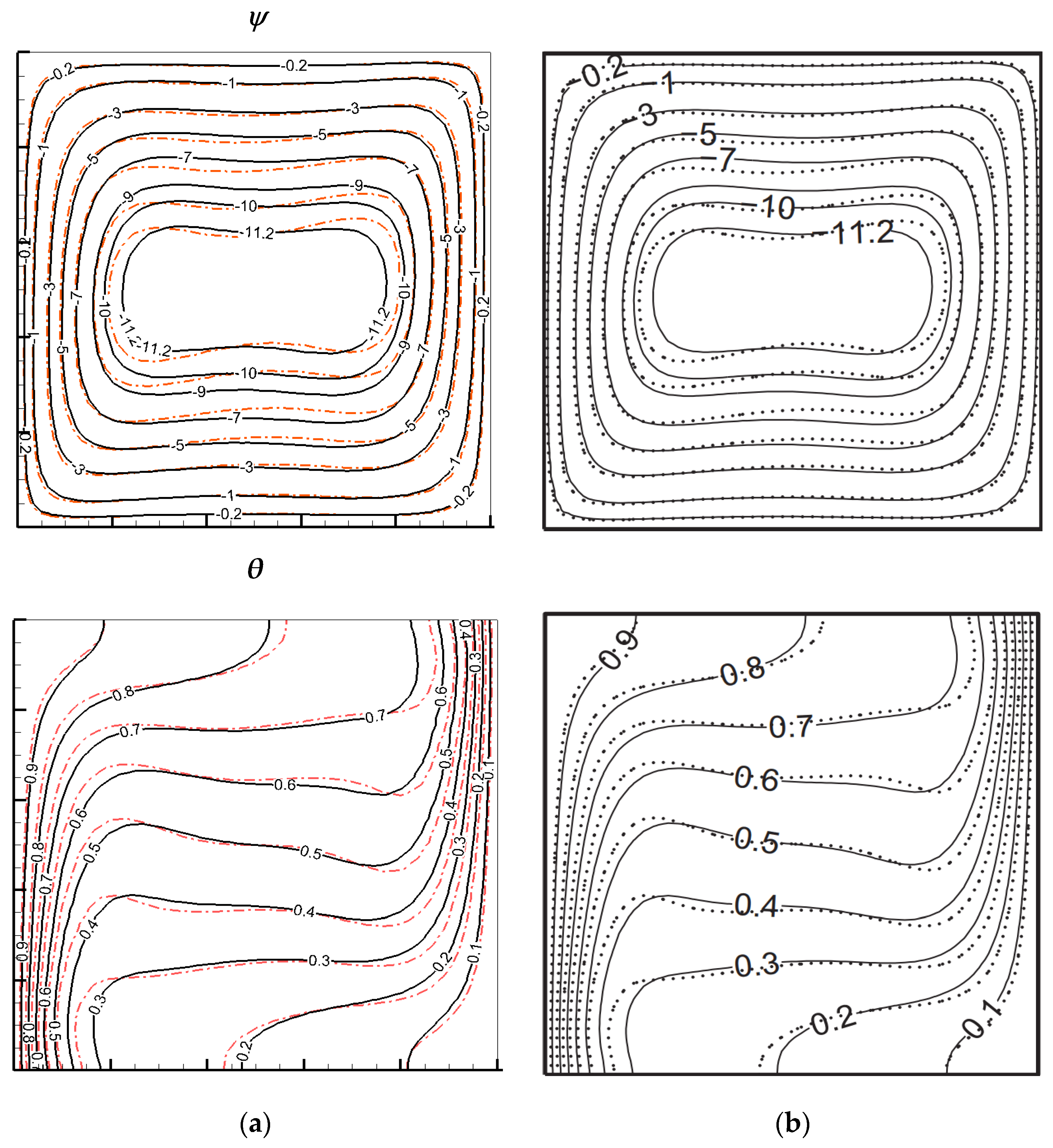
In order to achieve valid results, the present findings were compared to the numerical solution of the fluid flow and heat transfer inside a square enclosure that was heated differentially. They contained a nanofluid model for the R a = 10 4 with nanofluid concentration at ϕ = 0.2 against the numerical computation of Basak and Chamkha [24]. It was verified that the current code and earlier research published in the literature are in good agreement, as shown in Figure 3. Additionally, Table 3 displays the variations in the simulated average Nusselt number along a heated wall from the present code which was compared with the results that exist in the literature, which Basak and Chamkha found very accurate for different high Rayleigh numbers ( R a = 10 3 , 10 4   and   10 5 ) and for different nanofluid concentrations ( 0 ,   0.1 ,   and   0.2 ) .
Another comparison has been made with Ben-Nakhi and Chamkha [55] in terms of using a baffle attached to the horizontal adiabatic wall, as shown in Figure 4. It shows a good agreement with this model’s results.

3. Results and Discussion

FEM is employed to examine the heat transfer and fluid behavior of a baffle-mounted enclosure with a thick vertical wall. The results are presented in various domains of the parameters, which include the Rayleigh number ( 10 3     R a   10 6 ) , nanoparticle’s concentration ( ϕ = 0 ,   0.02 ,   0.04 ,   and   0.06 ) ,   thermal conductivity ratio ( 0.1 K r 10 )   of the thick wall, baffle angles ( 30     Φ     150 ) , and the Pr = 6.8, and confirms their impacts on the streamlines and isotherms patterns.

3.1. Effect of Rayleigh Number

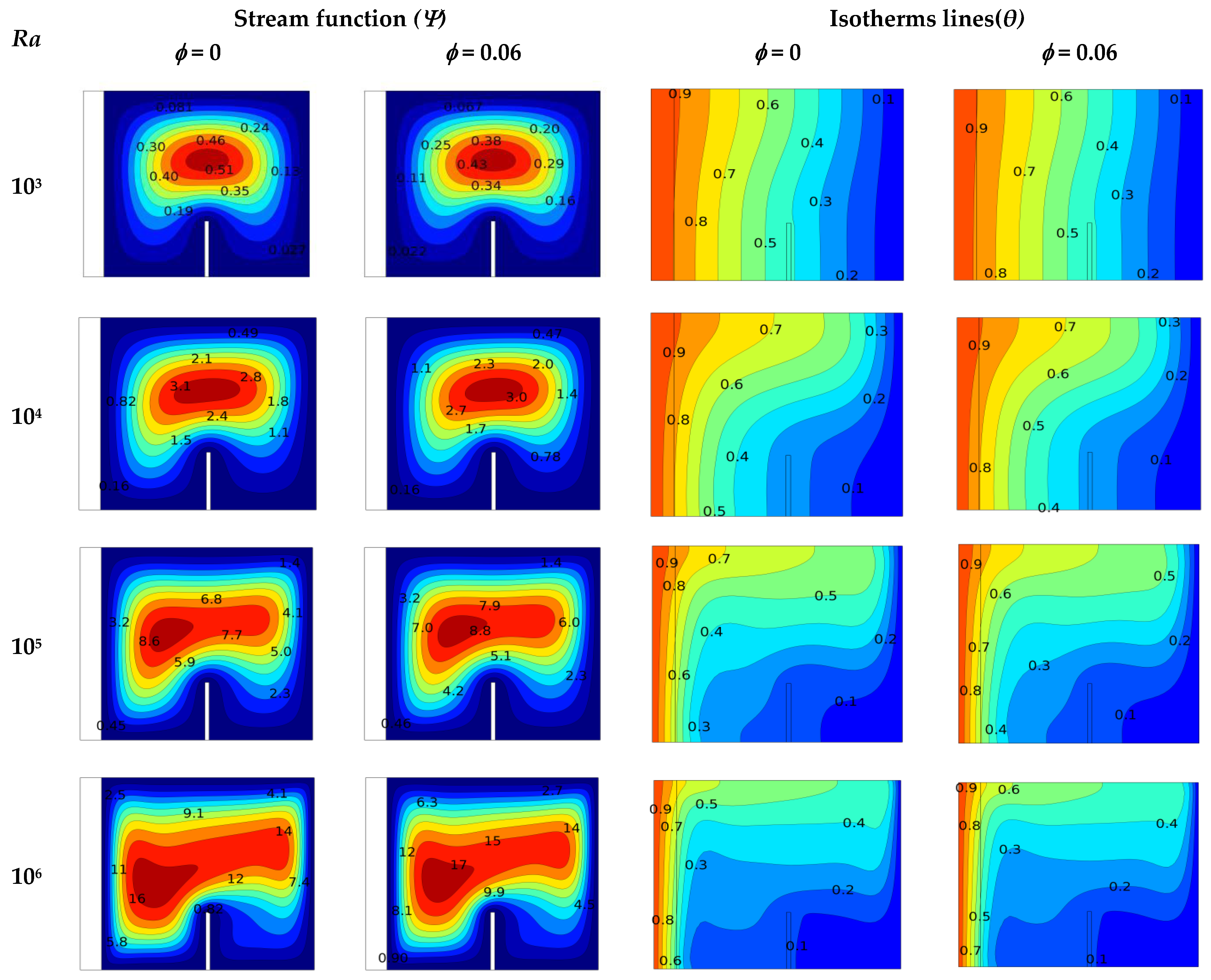
The effect of the Rayleigh number, which ranges from 10 3 to 10 6 , on the streamlines and isothermal patterns is observed in this section for the present configuration of a pure fluid and Cu–water nanofluid for the case of the volume fraction ϕ = 0.06 and the thermal conductivity ratio K r = 1 . Moreover, the mounded baffle effect on the flow and temperature gradient of fluid within the enclosure has been illustrated in Figure 5. The stream patterns inside the enclosure for the base fluid and Cu –water are displayed in the left two columns. Streamlines are generated within an enclosure and begin with the hot wall, travel over the top adiabatic wall, turn over the cold wall, and then round the baffle, and over again, for each case of R a . The baffle joins to the bottom wall to hold the flow moving toward the hot wall. When R a = 10 3 , flow movement within an enclosure is small, and the center of the stream patterns take place above the baffle. This is due to the low bounce generated at this value of R a   and the stream function value Ψ = 0.5 for water and nanofluid. As the Ra increases (Ra = 10 4 and 10 6 ), flow behavior appears to be strong, and the stream function value reaches Ψ = 17 , for the case of the nanofluid, and the center of the stream patterns shift to the left area between the baffle and the hot wall. This results from receiving a higher buoyancy effect by the inner fluid. In addition, the profile of the stream patterns changes to a triangular shape.
The two right columns of Figure 5 show the isotherms patterns within an enclosure for a base fluid and nanofluid of φ = 0.06 concentration and for a lower value of Rayleigh number ( R a = 10 3   and   10 4 ) . The isotherms patterns were parallel to the vertical walls of the enclosure for pure water as well as for nanofluid. This shows an indication of conduction-dominated heat transfer in this case. Increasing the Rayleigh number to 10 4 , the isothermal patterns turn about parallel to the enclosure’s top wall, and its shape changes to smooth curves because the convection seems to have an observable effect. Again, increasing the value of the Rayleigh number to R a = 10 6 and enhancing the strength of the buoyancy force and convection appear to have a more substantial impact, so at the wall interface the dimensionless temperature declines from 0.9 for R a = 10 3 to 0.6 for R a = 10 6 for nanofluid. Finally, the nanoparticle presented in the base fluid influences the flow strength inside an enclosure. Additionally, the nanofluid effect enhances as the volume fraction ( ϕ )   boosts, as in thermal conductivity. The combined effect of an increment in the nanoparticles concentration and the Rayleigh number leads to a decline in the wall dimensionless temperature, which is evidence of an enhancement in heat transfer.
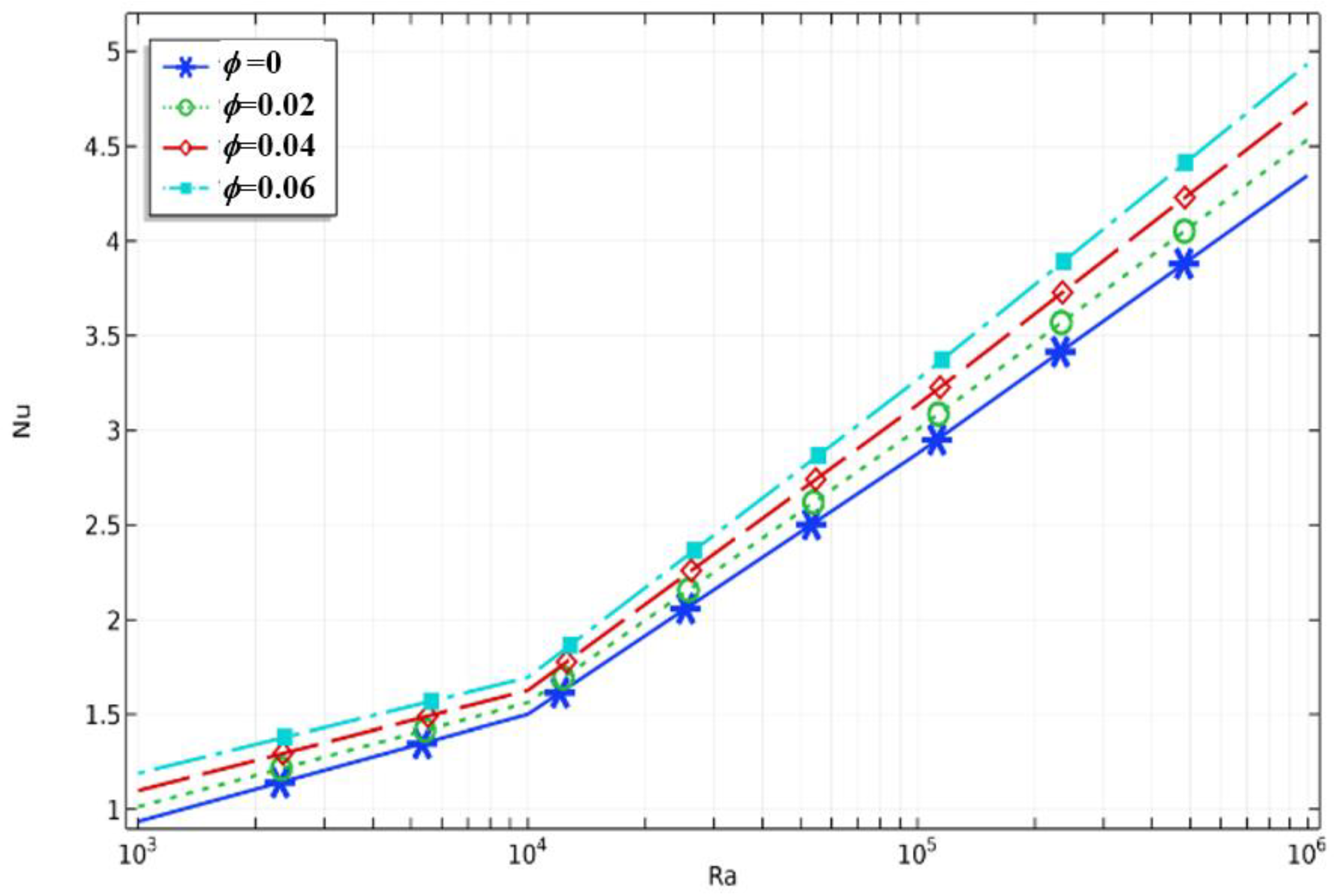
Figure 6 shows how the average Nusselt number has an impact along the left wall and the Rayleigh numbers for different volume fractions and baffles. It shows that   ( N u )   corresponds with the nanofluid when it is high compared to the base fluid. This is due to a high buoyant effect generated by good heat transfer to the inner fluid as a result of an enhancement in the thermal properties, and the stream function becomes stronger. Additionally, as the volume percentage of nanoparticles increases, the average Nusselt number and heat transfer rate increase. The maximum Nusselt number equals N u = 5.5 , corresponding to the nanofluid for the Rayleigh numbers R a = 10 6 .

3.2. Effect of Baffle Inclination Angle

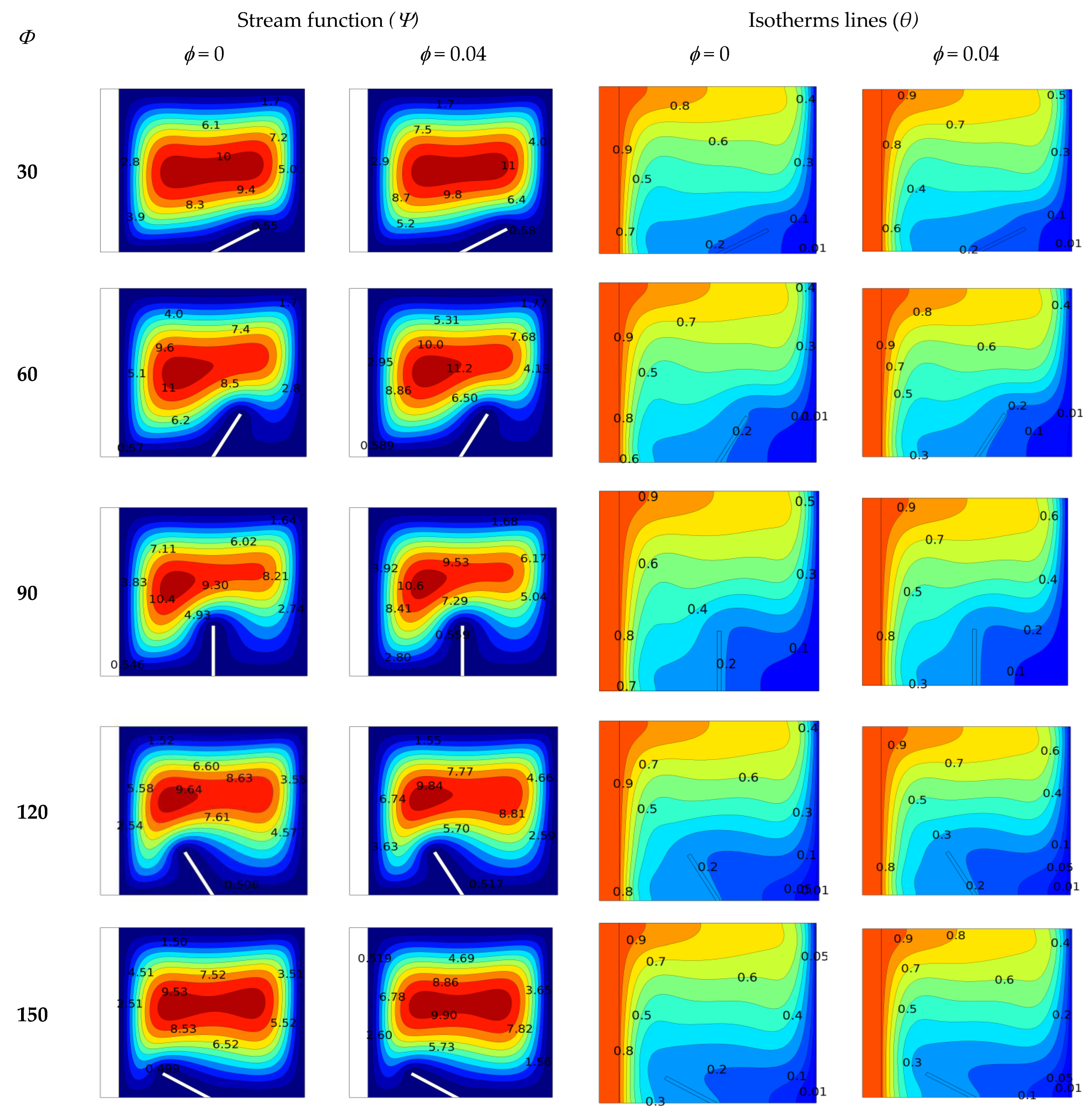
The effect of the baffle angle in ranges 30, 60, 90, 120, and 150 on the streamline and isothermal patterns is observed in this section for the present configuration of a pure fluid as well as a Cu –water nanofluid for the case of the volume fraction Φ = 0.04 ,   thermal conductivity ratio K r = 10 , and the Rayleigh number = 10 5 . A baffle within the enclosure controls two types of influence: the first being the influence on the flow performance because it serves as a barrier, and the second being the influence on the thermal field because of its good conductive properties.
Two left columns of Figure 7 display clockwise stream patterns of the flow within an enclosure. The presence of a solid baffle within the enclosure baffle serves as a barrier to the flow circulation of fluid. It separates the flow in the field near the enclosure walls and reduces its strength, which appears as a remarkable defect in in-stream patterns. The value of ( Ψ ) is affected by changing the value of the baffle angle from (30) to (60) and increasing the value from ( Ψ = 11   t o   11.2 ) ; there is no separation in this range of angle and the flow above the baffle was enhanced. While they decrease as the angle value reaches ( > 60 ) , in this case the baffle blocking becomes intense on the flow circulation which causes a decrease in flow movement and separates the flow on both sides. The maximum and minimum stream function values occurred in the case of the nanofluid corresponding to the angles Φ = 60 and Φ = 120 , equal to ( Ψ = 11.2 ) and ( Ψ = 9.84 ) , respectively. Moreover, the stream’s maximum function values take place at the middle of the enclosure, and the center of circulation flow position changes with the baffle angle change.
From the two columns on the right of Figure 7, it can be observed that as the angle of the baffle reaches the value of ( Φ = 30 ) , the blocking effect of the baffle on the flow circulation remains low. Moreover, the fluid flows easily from the hot wall around the other walls of the enclosure till it reaches the cold side and then returns so that the fluid flow is moderate due to the buoyancy force and the heat transfer. Therefore, the heat transfer rate by the inner fluid is enhanced so that the local temperature of the area near the hot wall drops. As can be remarked from low-temperature lines, it takes up a large space and gradually deflects at the top of the baffle inside the enclosure. When there is a further increase in the angle up to ( Φ   >   30 ) , the baffle at this angle value has a high blocking effect on the fluid flow inside the enclosure. Therefore, when the flow becomes limited and separated between the baffle and the hot wall, so does the cold wall from the other side. The temperature in the region between the baffle and the hot wall increased due to a decline in heat transfer through the inner fluid region. This indicates that the baffle contributes to the obstruction of the convection heat transfer. Additionally, it was observed that the baffle angle affects the core of the recirculation.
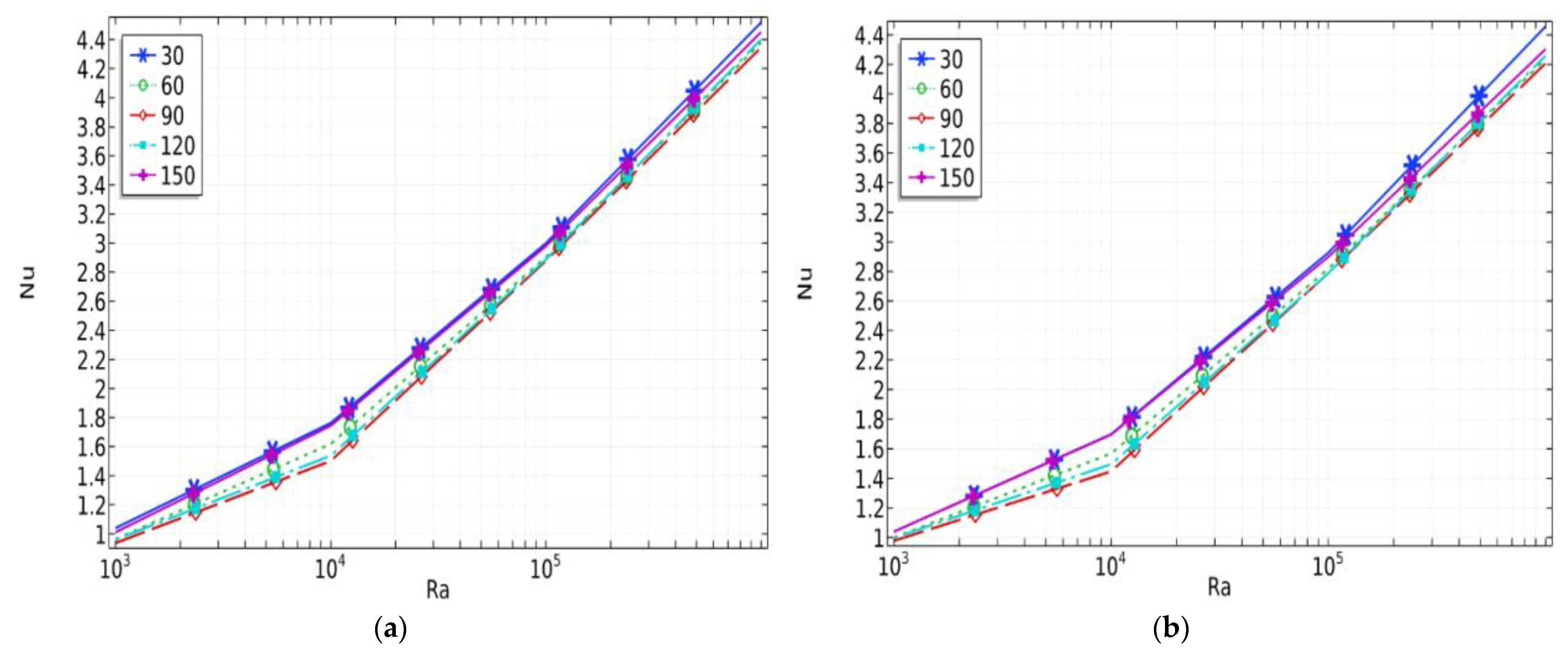
Figure 8a,b show the impact of the average Nusselt number along the conductive left wall due on adjusting the baffle angle for various Rayleigh number ranges. Fundamentally, the effect of the baffle angle has substantial outcomes on the average Nusselt number. The maximum average Nusselt number is obtained corresponding to the angle of Φ = 30 due to the blocking effect of the baffle on the flow, so fluids slightly move around the boundary wall and transfer heat. The Cu–water) nanofluid with ( ϕ = 0.04 ) volume fraction shows an enhancement in the value of ( N u ) as compared with water; this is associated with the improvement of the fluid thermal properties. While the minimum value corresponds with the angle value of ( Φ = 90 ) , which is equal to ( Ψ = 9.84 ) , the increase in the baffle angle ( Φ > 90 ) means the Nusselt number value rises over a small amount and stops at   ( Φ = 150 ) . In addition, the average Nusselt number and the heat distribution enhanced for the nanoparticle volume fraction increased.

3.3. Effect Thermal Conductivity Ratio

Figure 9 shows how changing the thermal conductivity ratio along the conductive wall has an impact for a range of K r = 0.1 ,   1 ,   and 10 upon the streamlines and isothermal patterns for the present configuration of both the pure fluid and ( Cu –water) nanofluid for the case of the volume fraction ϕ = 0.02 and the Rayleigh number Ra= 10 4 with a baffle at a vertical position. The right two columns display the isothermal patterns, whereas the two left columns display the streamline patterns. It is evident that the K r of the solid wall impacts the wall temperature and fluid flow behavior. It can be observed that the flow strength was considerable and at its maximum for a high K r of the wall. For the low values of K r , i.e., 0.1, the wall thermal resistance is extremely high; the gradient of the isothermal lines is lower and denser, and it is easier to observe that inside the area of the wall; this shows that a limited amount of heat is transferred to the inner fluid inside the enclosure. Additional increases in the conductivity ratio from 0.1 to 10 lead to decreases in the hot wall’s thermal resistance and the wall transfers extra heat to the inner fluid. It can be easy to recognize that from the isothermal lines as the gradient in that area of the wall became significant and the convection movements inside the enclosure. Concerning the flow field, as the conductivity ratio increases, the degree of stream function increases, that refers to the flow intensity within the enclosure walls above the baffle increase. This is because the temperature gradient at the hot wall increases with the increase in the K r . It was also observed that the convection strength of fluid becomes more effective for the larger values of K r .
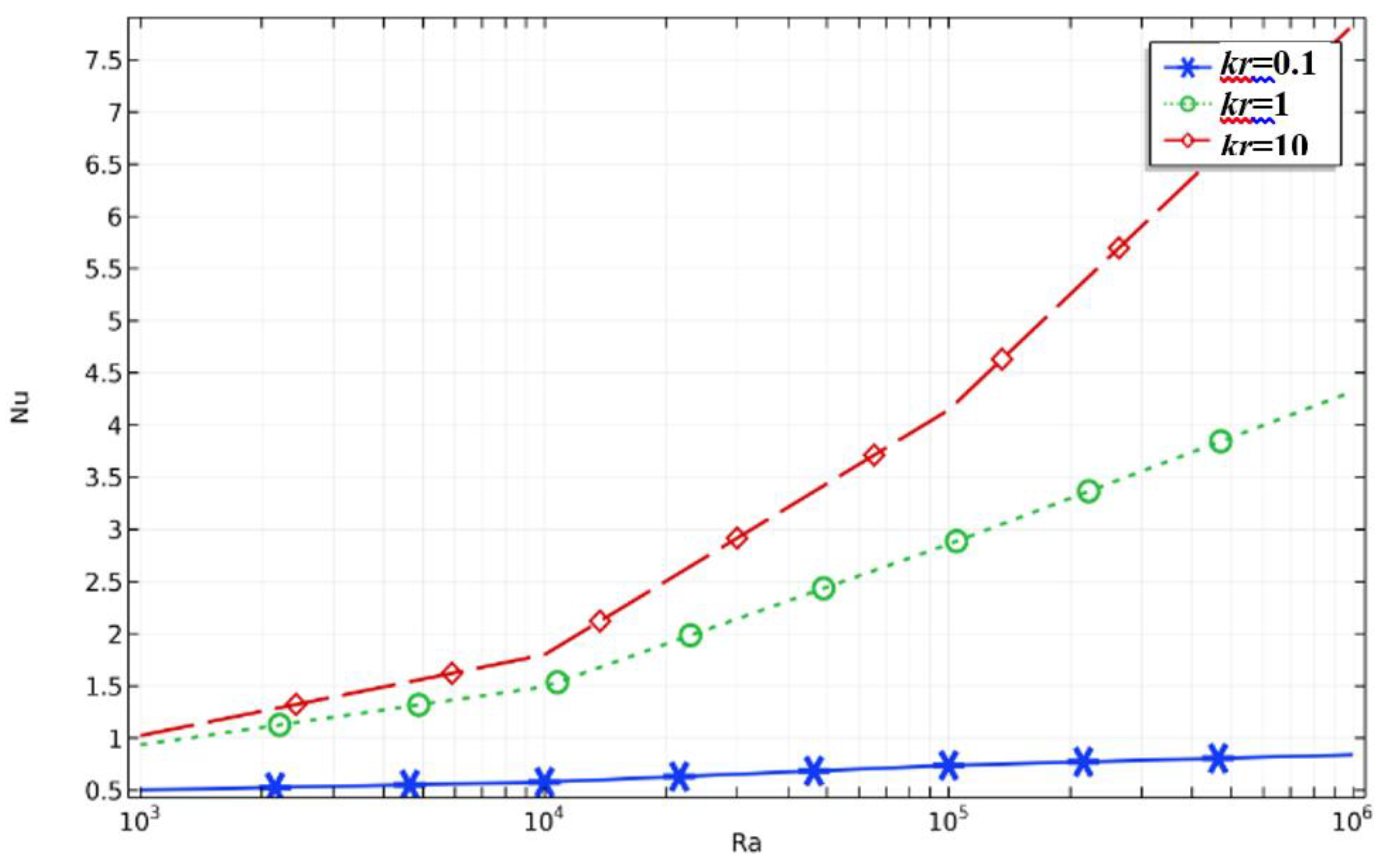
Figure 10 shows the ranges of the average Nusselt number, the thermal conductivity ratio, the Rayleigh number for various values, the volume fraction ranges ϕ = 0   t o   0.06 , and the angle of inclination of the baffle Φ = 90 ° . As shown, the convective flow strength and heat transmission are improved by increasing the Rayleigh number and thus increasing the average Nusselt number. It is also observed that the convective strength of the fluid becomes more effective for the maximum K r .

4. Conclusions

The combined study on the impact of a baffle length and the angle of inclination of the baffle in a square enclosure packed with a Cu –water nanofluid has been investigated numerically. The variables under consideration were resolved by employing the finite element method, which is validated against some previously published papers and found to be in good agreement. The following is a summary of the paper’s key findings:
  • A significant effect was observed while raising the value of the Rayleigh number ( R a ) on both the streamlines and isothermal patterns on the average Nusselt number. This shows the improvement in the rate of heat distribution, where the nanofluid effect is greater than that of the pure fluid.
  • Thermal performance was significantly influenced by the baffle’s inclination angle, flow behavior, and on the average Nusselt number. The heat transfer was improved for the angle closure to 30. The maximum value of the stream function occurred for the case of nanofluid at Φ = 60 , which is equal to Ψ = 11.2 , whereas they decreased when Φ > 60 , while for the minimum stream function Ψ decreased to 9.84. For the critical angle at Φ = 90 , the baffle had an excellent barrier effect on the flow and caused separate cells in the region on both sides.
  • The parameter K r of the left wall remarkably influences streamlines, isothermal patterns, and the average Nusselt number. The increase in the K r   raises the conductivity of the solid wall so that the heat transmitted across the thick wall increases and the temperature gradients pass the solid–fluid interface. Therefore, it can be seen that the thermal conductivity ratio acts as a control parameter that impacts the temperature profile within the enclosure. Moreover, the maximum stream function value was attained for all nanoparticle concentration values.

Author Contributions

Conceptualization, K.A.-F. and U.P.; methodology, K.A.-F.; software, B.A.-M. and F.A.; validation, B.A.-M. and U.P.; investigation, K.L., resources, B.A.-M.; writing—original draft preparation, B.A.-M. and K.L.; writing—review and editing, U.P. and I.E.S.; supervision, K.A.-F.; project administration, F.A.; funding acquisition, I.E.S. All authors have read and agreed to the published version of the manuscript.

Funding

This research received no external funding.

Data Availability Statement

Not applicable.

Conflicts of Interest

The authors declare no conflict of interest.

Nomenclature

CpSpecific heat (KJ/kg.K)
DDimensionless wall thickness
gGravitational acceleration (m/s2)
kThermal conductivity (W/m·K)
LEnclosure length (m)
NuNusselt number
PDimensionless pressure
PrPrandtl number
RaRayleigh number
TDimensional temperature
UDimensionless velocity component X-direction
VDimensionless velocity component Y-direction
XDimensionless-coordinates
YDimensionless-coordinates
Greek symbols
αthermal diffusivity (m2/s)
βthermal expansion coefficient (1/T)
µDynamic viscosity (kg·s/m)
θDimensionless temperature
ΨAbsolute stream function
Subscripts
ccold
hhot
loclocal

References

  1. Andrzejczyk, R.; Muszynski, T. An experimental investigation on the effect of new continuous core-baffle geometry on the mixed convection heat transfer in shell and coil heat exchanger. Appl. Therm. Eng. 2018, 136, 237–251. [Google Scholar] [CrossRef]
  2. Chen, H.-T.; Chang, Y.-L.; Lin, P.-Y.; Chiu, Y.-J.; Chang, J.-R. Numerical study of mixed convection heat transfer for vertical annular finned tube heat exchanger with experimental data and different tube diameters. Int. J. Heat Mass Transf. 2017, 118, 931–947. [Google Scholar] [CrossRef]
  3. Abdulsahib, A.D.; Al-Farhany, K. Numerical Investigation of the Nanofluid Mixed Convection on Two Layers Enclosure with Rotating Cylinder: High Darcy Number Effects; Shafik, S.S., Roomi, A.B., Sharrad, F.I., Eds.; IOP Publishing Ltd.: London, UK, 2020. [Google Scholar]
  4. Olayemi, O.A.; Khaled, A.-F.; Temitope, O.J.; Victor, O.O.; Odetunde, C.B.; Adegun, I.K. Parametric study of natural convection heat transfer from an inclined rectangular cylinder embedded in a square enclosure. Aust. J. Mech. Eng. 2021, 1–14. [Google Scholar] [CrossRef]
  5. Mathew, V.; Hotta, T.K. Numerical investigation on optimal arrangement of IC chips mounted on a SMPS board cooled under mixed convection. Therm. Sci. Eng. Prog. 2018, 7, 221–229. [Google Scholar] [CrossRef]
  6. Hadavand, M.; Yousefzadeh, S.; Akbari, O.A.; Pourfattah, F.; Nguyen, H.; Asadi, A. A numerical investigation on the effects of mixed convection of Ag-water nanofluid inside a sim-circular lid-driven cavity on the temperature of an electronic silicon chip. Appl. Therm. Eng. 2019, 162, 114298. [Google Scholar] [CrossRef]
  7. Mathew, V.K.; Hotta, T.K. Role of PCM based mini-channels for the cooling of multiple protruding IC chips on the SMPS board—A numerical study. J. Energy Storage 2019, 26, 100917. [Google Scholar] [CrossRef]
  8. Abdulsahib, A.D.; Al-Farhany, K. Review of the Effects of Stationary/Rotating Cylinder in a Cavity on the Convection Heat Transfer in Porous Media with/without Nanofluid. Math. Model. Eng. Probl. 2021, 8, 356–364. [Google Scholar] [CrossRef]
  9. Al-Farhany, K.; Al-Muhja, B.; Ali, F.; Khan, U.; Zaib, A.; Raizah, Z.; Galal, A.M. The Baffle Length Effects on the Natural Convection in Nanofluid-Filled Square Enclosure with Sinusoidal Temperature. Molecules 2022, 27, 4445. [Google Scholar] [CrossRef]
  10. Edalatpour, M.; Solano, J.P. Thermal-hydraulic characteristics and exergy performance in tube-on-sheet flat plate solar collectors: Effects of nanofluids and mixed convection. Int. J. Therm. Sci. 2017, 118, 397–409. [Google Scholar] [CrossRef]
  11. Xiao, C.; Liao, Q.; Fu, Q.; Huang, Y.; Xia, A.; Chen, H.; Zhu, X. Numerical investigation of laminar mixed convection of microalgae slurry flowing in a solar collector. Appl. Therm. Eng. 2020, 175, 115366. [Google Scholar] [CrossRef]
  12. Laouer, A.; Al-Farhany, K.; Al-Dawody, M.F.; Hashem, A.L. A numerical study of phase change material melting enhancement in a horizontal rectangular enclosure with vertical triple fins. Int. Commun. Heat Mass Transf. 2022, 137. [Google Scholar] [CrossRef]
  13. Laouer, A.; Al-Farhany, K. Melting of nano-enhanced phase change material in a cavity heated sinusoidal from below: Numerical study using lattice Boltzmann method. Heat Transf. 2022, 51, 5952–5970. [Google Scholar] [CrossRef]
  14. Shin, D.-H.; Kim, C.S.; Park, G.-C.; Cho, H.K. Experimental analysis on mixed convection in reactor cavity cooling system of HTGR for hydrogen production. Int. J. Hydrogen Energy 2017, 42, 22046–22053. [Google Scholar] [CrossRef]
  15. Kasam, A.; Lee, J.I.; Shwageraus, E. Numerical study of heat transfer in ascending mixed convection with internal heat generation. Ann. Nucl. Energy 2019, 133, 138–144. [Google Scholar] [CrossRef]
  16. Al-Farhany, K.; Abdulsahib, A.D. Study of mixed convection in two layers of saturated porous medium and nanofluid with rotating circular cylinder. Prog. Nucl. Energy 2021, 135, 103723. [Google Scholar] [CrossRef]
  17. Qi, C.; Cui, X.; Liu, Y.; Yang, Z.; Huang, C. Natural Convection Heat Transfer of Liquid Metal Gallium Nanofluids in a Rectangular Enclosure. Heat Transfer—Asian Res. 2015, 46, 1–17. [Google Scholar] [CrossRef]
  18. Al-Chlaihawi, K.K.; Alaydamee, H.H.; Faisal, A.E.; Al-Farhany, K.; Alomari, M.A. Newtonian and non-Newtonian nanofluids with entropy generation in conjugate natural convection of hybrid nanofluid-porous enclosures: A review. Heat Transf. 2021, 51, 1725–1745. [Google Scholar] [CrossRef]
  19. De Vahl Davis, G. Natural convection of air in a square cavity: A bench mark numerical solution. Int. J. Numer. Methods Fluids 1983, 3, 249–264. [Google Scholar] [CrossRef]
  20. Sankar, M.; Do, Y. Numerical simulation of free convection heat transfer in a vertical annular cavity with discrete heating. Int. Commun. Heat Mass Transf. 2010, 37, 600–606. [Google Scholar] [CrossRef]
  21. Varol, Y.; Oztop, H.F.; Koca, A. Effects of inclination angle on conduction—Natural convection in divided enclosures filled with different fluids. Int. Commun. Heat Mass Transf. 2010, 37, 182–191. [Google Scholar] [CrossRef]
  22. Sheikhzadeh, G.A.; Arefmanesh, A.; Kheirkhah, M.; Abdollahi, R. Natural convection of Cu–water nanofluid in a cavity with partially active side walls. Eur. J. Mech. B/Fluids 2011, 30, 166–176. [Google Scholar] [CrossRef]
  23. Ternik, P.; Rudolf, R. Heat transfer enhancement for natural convection flow of water-based nanofluids in a square enclosure. Int. J. Simul. Model. 2012, 11, 29–39. [Google Scholar] [CrossRef]
  24. Basak, T.; Chamkha, A.J. Heatline analysis on natural convection for nanofluids confined within square cavities with various thermal boundary conditions. Int. J. Heat Mass Transf. 2012, 55, 5526–5543. [Google Scholar] [CrossRef]
  25. Cianfrini, M.; Corcione, M.; Quintino, A.; Marta, C.; Massimo, C.; Alessandro, Q. Natural convection in square enclosures differentially heated at sides using alumina-water nanofluids with temperature-dependent physical properties. Therm. Sci. 2015, 19, 591–608. [Google Scholar] [CrossRef]
  26. Redouane, F.; Jamshed, W.; Devi, S.S.U.; Amine, B.M.; Safdar, R.; Al-Farhany, K.; Eid, M.R.; Nisar, K.S.; Abdel-Aty, A.-H.; Yahia, I.S. Influence of entropy on Brinkman–Forchheimer model of MHD hybrid nanofluid flowing in enclosure containing rotating cylinder and undulating porous stratum. Sci. Rep. 2021, 11, 1–26. [Google Scholar] [CrossRef]
  27. Alomari, M.A.; Al-Farhany, K.; Hashem, A.L.; Al-Dawody, M.F.; Redouane, F.; Olayemi, O.A. Numerical Study of MHD Natural Convection in Trapezoidal Enclosure Filled with (50%MgO-50%Ag/Water) Hybrid Nanofluid: Heated Sinusoidal from Below. Int. J. Heat Technol. 2021, 39, 1271–1279. [Google Scholar] [CrossRef]
  28. Ghassemi, M.; Pirmohammadi, M.; Sheikhzadeh, A. A Numerical Study of Natural Convection in a Tilted Cavity with Two Baffles Attached to its Isothermal Walls. WSEAS Trans. Fluid Mech. 2007, 2, 61–68. [Google Scholar]
  29. Sheikhzadeh, G.A.; Pirmohammadi, M.; Ghassemi, M. A Numerical Study of Natural Convection in a Cavity with Two Fins Attached to Its Vertical Walls; American Society of Mechanical Engineers: New York, NY, USA, 2007; pp. 453–460. [Google Scholar]
  30. Elatar, A.; Teamah, M.A.; Hassab, M.A. Numerical study of laminar natural convection inside square enclosure with single horizontal fin. Int. J. Therm. Sci. 2016, 99, 41–51. [Google Scholar] [CrossRef]
  31. Torabi, M.; Keyhani, A.; Peterson, G. A comprehensive investigation of natural convection inside a partially differentially heated cavity with a thin fin using two-set lattice Boltzmann distribution functions. Int. J. Heat Mass Transf. 2017, 115, 264–277. [Google Scholar] [CrossRef]
  32. Al-Farhany, K.; Abdulkadhim, A.; Hamzah, H.K.; Ali, F.H.; Chamkha, A. MHD effects on natural convection in a U-shaped enclosure filled with nanofluid-saturated porous media with two baffles. Prog. Nucl. Energy 2022, 145, 104136. [Google Scholar] [CrossRef]
  33. Mahmoudi, A.H.; Shahi, M.; Raouf, A.H.; Ghasemian, A. Numerical study of natural convection cooling of horizontal heat source mounted in a square cavity filled with nanofluid. Int. Commun. Heat Mass Transf. 2010, 37, 1135–1141. [Google Scholar] [CrossRef]
  34. Habibzadeh, A.; Sayehvand, H.; Mekanik, A. Numerical Study of Natural Convection in a Partitioned Square Cavity Filled with Nanofluid. Int. J. Chem. Eng. Appl. 2011, 261–267. [Google Scholar] [CrossRef]
  35. Sayehvand, H.; Habibzadeh, A.; Mekanik, A. CFD analysis of natural convection heat transfer in a square cavity with partitions utilizing Al2O3 nanofluid. Int. J. Nano Dimens. 2012, 2, 191–200. [Google Scholar]
  36. Naoufal, Y.; Zaydan, M.; Rachid, S. Numerical study of natural convection in a square cavity with partitions utilizing Cu-Water nanofluid. Int. J. Innov. Res. Sci. Eng. Technol. 2015, 4, 10354–10367. [Google Scholar]
  37. Selimefendigil, F.; Öztop, H.F. Conjugate natural convection in a cavity with a conductive partition and filled with different nanofluids on different sides of the partition. J. Mol. Liq. 2016, 216, 67–77. [Google Scholar] [CrossRef]
  38. Costa, V.; Oliveira, M.; Sousa, A. Control of laminar natural convection in differentially heated square enclosures using solid inserts at the corners. Int. J. Heat Mass Transf. 2003, 46, 3529–3537. [Google Scholar] [CrossRef]
  39. Basak, T.; Anandalakshmi, R.; Singh, A.K. Heatline analysis on thermal management with conjugate natural convection in a square cavity. Chem. Eng. Sci. 2013, 93, 67–90. [Google Scholar] [CrossRef]
  40. Chamkha, A.J.; Ismael, M.A. Conjugate heat transfer in a porous cavity filled with nanofluids and heated by a triangular thick wall. Int. J. Therm. Sci. 2013, 67, 135–151. [Google Scholar] [CrossRef]
  41. Abdulkadhim, A.; Abed, A.M.; Al-Farhany, K. Computational investigation of conjugate heat transfer in cavity filled with saturated porous media. Front. Heat Mass Transf. 2018, 11, 12. [Google Scholar] [CrossRef]
  42. Al-Farhany, K.; Abdulkadhim, A. Numerical investigation of conjugate natural convection heat transfer in a square porous cavity heated partially from left sidewall. Int. J. Heat Technol. 2018, 36, 237–244. [Google Scholar] [CrossRef]
  43. Ishrat Zahan, M.A.A. Effect of conjugate heat transfer on flow of nanofluid in a rectangular enclosure. Int. J. Heat Technol. 2018, 36, 8. [Google Scholar]
  44. Menni, Y.; Chamkha, A.; Zidani, C.; Benyoucef, B. Numerical analysis of heat and nanofluid mass transfer in a channel with detached and attached baffle plates. Math. Model. Eng. Probl. 2019, 6, 52–60. [Google Scholar] [CrossRef]
  45. Menni, Y.; Chamkha, A.; Zidani, C.; Benyoucef, B. Heat and nanofluid transfer in baffled channels of different outlet models. Math. Model. Eng. Probl. 2019, 6, 21–28. [Google Scholar] [CrossRef]
  46. Ghachem, K.; Hassen, W.; Maatki, C.; Kolsi, L.; Al-Rashed, A.; Borjini, M. Numerical simulation of 3D natural convection and entropy generation in a cubic cavity equipped with an adiabatic baffle. Int. J. Heat Technol. 2018, 36, 1047–1054. [Google Scholar] [CrossRef] [Green Version]
  47. Keramat, F.; Dehghan, P.; Mofarahi, M.; Lee, C.-H. Numerical analysis of natural convection of alumina–water nanofluid in H-shaped enclosure with a V-shaped baffle. J. Taiwan Inst. Chem. Eng. 2020, 111, 63–72. [Google Scholar] [CrossRef]
  48. Al-Farhany, K.; Al-Dawody, M.F.; Hamzah, D.A.; Al-Kouz, W.; Said, Z. Numerical investigation of natural convection on Al2O3–Water porous enclosure partially heated with two fins attached to its hot wall: Under the MHD effects. Appl. Nanosci. 2021, 1–18. [Google Scholar] [CrossRef]
  49. Al-Farhany, K.; Al-Chlaihawi, K.K.; Al-Dawody, M.F.; Biswas, N.; Chamkha, A.J. Effects of fins on magnetohydrodynamic conjugate natural convection in a nanofluid-saturated porous inclined enclosure. Int. Commun. Heat Mass Transf. 2021, 126, 105413. [Google Scholar] [CrossRef]
  50. Al-Farhany, K.; Alomari, M.A.; Saleem, K.B.; Al-Kouz, W.; Biswas, N. Numerical investigation of double-diffusive natural convection in a staggered cavity with two triangular obstacles. Eur. Phys. J. Plus 2021, 136, 1–24. [Google Scholar] [CrossRef]
  51. Al-Kouz, W.; Medebber, M.A.; Elkotb, M.A.; Abderrahmane, A.; Aimad, K.; Al-Farhany, K.; Jamshed, W.; Moria, H.; Aldawi, F.; Saleel, C.A.; et al. Galerkin finite element analysis of Darcy–Brinkman–Forchheimer natural convective flow in conical annular enclosure with discrete heat sources. Energy Rep. 2021, 7, 6172–6181. [Google Scholar] [CrossRef]
  52. Alsabery, A.; Chamkha, A.; Saleh, H.; Hashim, I. Heatline visualization of conjugate natural convection in a square cavity filled with nanofluid with sinusoidal temperature variations on both horizontal walls. Int. J. Heat Mass Transf. 2016, 100, 835–850. [Google Scholar] [CrossRef]
  53. Abedini, A.; Armaghani, T.; Chamkha, A.J. MHD free convection heat transfer of a water–Fe3O4 nanofluid in a baffled C-shaped enclosure. J. Therm. Anal. 2018, 135, 685–695. [Google Scholar] [CrossRef]
  54. Abu-Nada, E.; Oztop, H.F. Effects of inclination angle on natural convection in enclosures filled with Cu–water nanofluid. Int. J. Heat Fluid Flow 2009, 30, 669–678. [Google Scholar] [CrossRef]
  55. Ben-Nakhi, A.; Chamkha, A.J. Effect of length and inclination of a thin fin on natural convection in a square enclosure. Numer. Heat Transfer Part A Appl. 2006, 50, 381–399. [Google Scholar] [CrossRef]
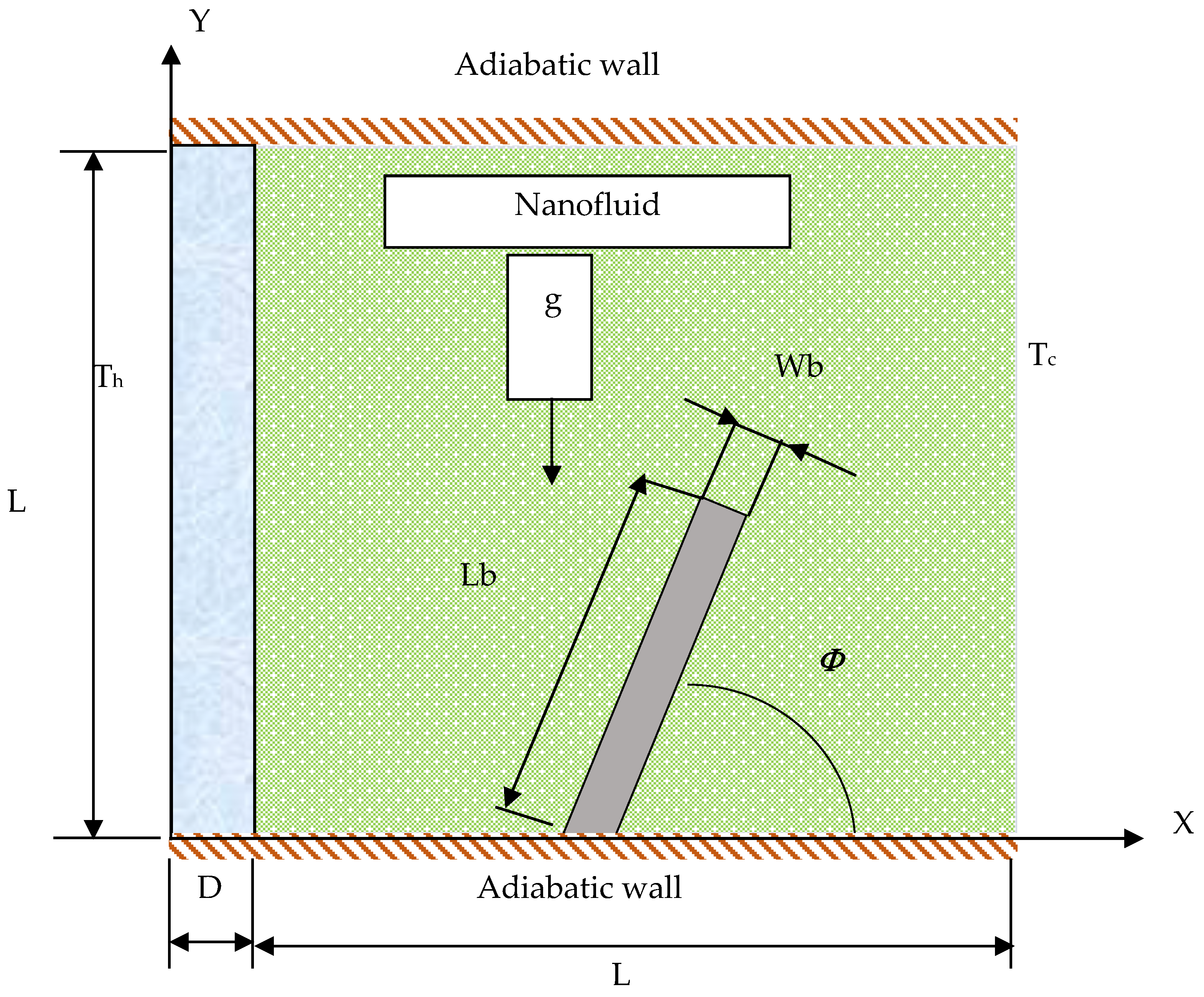
Figure 1. Physical Geometry of the Model.
Energies 15 06615 g001
Figure 2. The triangle mesh distribution of the enclosure.
Energies 15 06615 g002
Figure 3. Comparison of the (a) present results of isothermal patterns with (b) Basak and Chamkha [24] ( θ ) and stream function   ( Ψ ) for Cu–water nanofluids with R a = 10 5 and ϕ = 0.1 .
Energies 15 06615 g003
Figure 4. Comparison of the (a) Isothermal lines with previous results ( θ ) and stream function ( Ψ ) at P r = 0.707 ,   R a = 10 5 ,   S = 0.5 , and L f = 0.35   with (b) Ben-Nakhi and Chamkha [55].
Energies 15 06615 g004
Figure 5. Effect of Rayleigh number on streamlines and Isotherms for different volume fraction, K r = 1 and Φ = 90 .
Energies 15 06615 g005
Figure 6. Average Nusselt number graph for various Rayleigh number and solid volume fraction at K r = 1   and Φ = 90 .
Energies 15 06615 g006
Figure 7. Effect of baffle inclination angle (Φ) on streamlines (two left columns) and isotherms (two right columns) for different value of solid volume fraction with R a = 10 5 and K r = 10 .
Energies 15 06615 g007
Figure 8. Average Nusselt number graph for various baffle inclination angle with R a   and Φ at K r = 1 ,   at (a) ϕ = 0 ,   and (b) ϕ = 0.06 .
Energies 15 06615 g008
Figure 9. Effect of the hot thick wall on streamlines (two left columns) and isothermal patterns (two right columns) for different value of solid volume fraction at R a = 10 4 and Φ = 90 .
Energies 15 06615 g009
Figure 10. Average Nusselt number at various   R a and   K r of the solid wall at Φ = 90   a n d   ϕ = 0.06 .
Energies 15 06615 g010
Table 1. Thermophysical properties of fluid and Nanoparticles at T = 25 °C [22].
PropertiesPure WaterCu
Cp (J/kg. K)4179385
ρ (kg/m3)997.18933
µ (Pa·s)1.003 × 10⁻³-----
k (W/m. K)0.613401
β (1/K)21 × 10−51.67 × 10−5
Table 2. Shows the variation in the average Nusselt number (Nu) at left solid wall of square enclosure and the variation in number of mesh elements with Ra = 106, D = 0.3, and Kr = 10.
MeshMesh ElementsAverage Nusselt Number
Mesh116403.947593
Mesh223923.944723
Mesh338103.943674
Mesh495703.938316
Mesh524,9823.938331
Mesh637,2423.938329
Table 3. Comparison of average Nusselt number obtained in the present simulation and those of Basak and Chamkha [24], for Cu–water nanofluid.
Rayleigh Number (Ra)(ϕ)Present StudyBasak and Chamkha [24]
10301.117611.11
0.11.386271.38
0.21.767821.768
10402.275732.276
0.12.472802.477
0.22.62332.624
10504.741354.74
0.15.242205.243
0.25.649945.65
Publisher’s Note: MDPI stays neutral with regard to jurisdictional claims in published maps and institutional affiliations.